JP3615501B2 - Object forming method, object forming program, recording medium on which object forming program is recorded, and gaming apparatus - Google Patents
Object forming method, object forming program, recording medium on which object forming program is recorded, and gaming apparatus Download PDFInfo
- Publication number
- JP3615501B2 JP3615501B2 JP2001198853A JP2001198853A JP3615501B2 JP 3615501 B2 JP3615501 B2 JP 3615501B2 JP 2001198853 A JP2001198853 A JP 2001198853A JP 2001198853 A JP2001198853 A JP 2001198853A JP 3615501 B2 JP3615501 B2 JP 3615501B2
- Authority
- JP
- Japan
- Prior art keywords
- image
- character
- contour
- extracting
- parameter
- Prior art date
- Legal status (The legal status is an assumption and is not a legal conclusion. Google has not performed a legal analysis and makes no representation as to the accuracy of the status listed.)
- Expired - Fee Related
Links
Images


Classifications
-
- A63F13/10—
-
- A—HUMAN NECESSITIES
- A63—SPORTS; GAMES; AMUSEMENTS
- A63F—CARD, BOARD, OR ROULETTE GAMES; INDOOR GAMES USING SMALL MOVING PLAYING BODIES; VIDEO GAMES; GAMES NOT OTHERWISE PROVIDED FOR
- A63F13/00—Video games, i.e. games using an electronically generated display having two or more dimensions
- A63F13/60—Generating or modifying game content before or while executing the game program, e.g. authoring tools specially adapted for game development or game-integrated level editor
- A63F13/63—Generating or modifying game content before or while executing the game program, e.g. authoring tools specially adapted for game development or game-integrated level editor by the player, e.g. authoring using a level editor
-
- A—HUMAN NECESSITIES
- A63—SPORTS; GAMES; AMUSEMENTS
- A63F—CARD, BOARD, OR ROULETTE GAMES; INDOOR GAMES USING SMALL MOVING PLAYING BODIES; VIDEO GAMES; GAMES NOT OTHERWISE PROVIDED FOR
- A63F13/00—Video games, i.e. games using an electronically generated display having two or more dimensions
- A63F13/45—Controlling the progress of the video game
-
- A—HUMAN NECESSITIES
- A63—SPORTS; GAMES; AMUSEMENTS
- A63F—CARD, BOARD, OR ROULETTE GAMES; INDOOR GAMES USING SMALL MOVING PLAYING BODIES; VIDEO GAMES; GAMES NOT OTHERWISE PROVIDED FOR
- A63F13/00—Video games, i.e. games using an electronically generated display having two or more dimensions
- A63F13/50—Controlling the output signals based on the game progress
- A63F13/52—Controlling the output signals based on the game progress involving aspects of the displayed game scene
-
- A—HUMAN NECESSITIES
- A63—SPORTS; GAMES; AMUSEMENTS
- A63F—CARD, BOARD, OR ROULETTE GAMES; INDOOR GAMES USING SMALL MOVING PLAYING BODIES; VIDEO GAMES; GAMES NOT OTHERWISE PROVIDED FOR
- A63F2300/00—Features of games using an electronically generated display having two or more dimensions, e.g. on a television screen, showing representations related to the game
- A63F2300/30—Features of games using an electronically generated display having two or more dimensions, e.g. on a television screen, showing representations related to the game characterized by output arrangements for receiving control signals generated by the game device
- A63F2300/303—Features of games using an electronically generated display having two or more dimensions, e.g. on a television screen, showing representations related to the game characterized by output arrangements for receiving control signals generated by the game device for displaying additional data, e.g. simulating a Head Up Display
-
- A—HUMAN NECESSITIES
- A63—SPORTS; GAMES; AMUSEMENTS
- A63F—CARD, BOARD, OR ROULETTE GAMES; INDOOR GAMES USING SMALL MOVING PLAYING BODIES; VIDEO GAMES; GAMES NOT OTHERWISE PROVIDED FOR
- A63F2300/00—Features of games using an electronically generated display having two or more dimensions, e.g. on a television screen, showing representations related to the game
- A63F2300/60—Methods for processing data by generating or executing the game program
- A63F2300/6009—Methods for processing data by generating or executing the game program for importing or creating game content, e.g. authoring tools during game development, adapting content to different platforms, use of a scripting language to create content
- A63F2300/6018—Methods for processing data by generating or executing the game program for importing or creating game content, e.g. authoring tools during game development, adapting content to different platforms, use of a scripting language to create content where the game content is authored by the player, e.g. level editor or by game device at runtime, e.g. level is created from music data on CD
-
- A—HUMAN NECESSITIES
- A63—SPORTS; GAMES; AMUSEMENTS
- A63F—CARD, BOARD, OR ROULETTE GAMES; INDOOR GAMES USING SMALL MOVING PLAYING BODIES; VIDEO GAMES; GAMES NOT OTHERWISE PROVIDED FOR
- A63F2300/00—Features of games using an electronically generated display having two or more dimensions, e.g. on a television screen, showing representations related to the game
- A63F2300/60—Methods for processing data by generating or executing the game program
- A63F2300/63—Methods for processing data by generating or executing the game program for controlling the execution of the game in time
- A63F2300/638—Methods for processing data by generating or executing the game program for controlling the execution of the game in time according to the timing of operation or a time limit
-
- A—HUMAN NECESSITIES
- A63—SPORTS; GAMES; AMUSEMENTS
- A63F—CARD, BOARD, OR ROULETTE GAMES; INDOOR GAMES USING SMALL MOVING PLAYING BODIES; VIDEO GAMES; GAMES NOT OTHERWISE PROVIDED FOR
- A63F2300/00—Features of games using an electronically generated display having two or more dimensions, e.g. on a television screen, showing representations related to the game
- A63F2300/60—Methods for processing data by generating or executing the game program
- A63F2300/65—Methods for processing data by generating or executing the game program for computing the condition of a game character
-
- A—HUMAN NECESSITIES
- A63—SPORTS; GAMES; AMUSEMENTS
- A63F—CARD, BOARD, OR ROULETTE GAMES; INDOOR GAMES USING SMALL MOVING PLAYING BODIES; VIDEO GAMES; GAMES NOT OTHERWISE PROVIDED FOR
- A63F2300/00—Features of games using an electronically generated display having two or more dimensions, e.g. on a television screen, showing representations related to the game
- A63F2300/60—Methods for processing data by generating or executing the game program
- A63F2300/66—Methods for processing data by generating or executing the game program for rendering three dimensional images
-
- A—HUMAN NECESSITIES
- A63—SPORTS; GAMES; AMUSEMENTS
- A63F—CARD, BOARD, OR ROULETTE GAMES; INDOOR GAMES USING SMALL MOVING PLAYING BODIES; VIDEO GAMES; GAMES NOT OTHERWISE PROVIDED FOR
- A63F2300/00—Features of games using an electronically generated display having two or more dimensions, e.g. on a television screen, showing representations related to the game
- A63F2300/80—Features of games using an electronically generated display having two or more dimensions, e.g. on a television screen, showing representations related to the game specially adapted for executing a specific type of game
- A63F2300/8076—Shooting
Description
【0001】
【発明の属する技術分野】
本発明は、任意の画像に基づいて例えばゲーム用のステージを形成するオブジェクト形成方法、オブジェクト形成プログラム、オブジェクト形成プログラムが記録された記録媒体、遊技装置、遊技方法、遊技プログラム、及び遊技プログラムが記録された記録媒体に関する。
【0002】
【従来の技術】
今日において、例えばCD−ROM,DVD−ROM或いは半導体メモリ等の記録媒体に記録されているゲームプログラムに基づいてビデオゲームを可能とするビデオゲーム機が普及している。
【0003】
このビデオゲーム機は、プレーヤのコントローラの操作に応じて上記DVD−R等の記録媒体に記録されたゲームプログラムを読み出し、このゲームプログラムに対応するステージ画像やキャラクタ画像をモニタ装置に表示することでビデオゲームを楽しむようになっている。
【0004】
【発明が解決しようとする課題】
しかし、従来のビデオゲームは、予めメーカ側で作成されたステージでプレイするようになっているため、そのビデオゲームを繰り返しプレイしていると、プレーヤは、同じステージを何度もプレイすることとなり、そのステージで次に起こる現象を憶えてしまい或いは予測可能となる。このため、従来のビデオゲームは、繰り返しプレイしているうちに、そのビデオゲームの面白みが徐々に薄れ、いずれはプレーヤに飽きられてしまう問題があった。
【0005】
本発明は上述の課題に鑑みてなされたものであり、プレーヤに対して常に新規なステージを提供することで、ゲームに対するプレーヤの慣れや飽きを防止することができるようなオブジェクト形成方法、オブジェクト形成プログラム、オブジェクト形成プログラムが記録された記録媒体、遊技装置、遊技方法、遊技プログラム、及び遊技プログラムが記録された記録媒体の提供を目的とする。
【0006】
【課題を解決するための手段】
本発明は、上述の課題を解決するために、プレーヤが作成し或いは選択した画像、さらには第三者から提供された画像に基づいてゲーム用のステージを形成する。これにより、略々無限の形態のステージを提供することができるため、プレーヤは、多くの未知のステージでゲームを楽しむことができ、面白くかつプレーヤを飽きさせないゲームを提供することができる。
【0007】
【発明の実施の形態】
本発明は、例えばDVD−ROM,CD−ROM,半導体メモリ等の記録媒体に記録されたゲームプログラムに基づいてビデオゲームを可能とするビデオゲーム機に適用することができる。
【0008】
[ビデオゲーム機の構成]
図1は、この本発明の実施の形態となるビデオゲーム機の要部の構成を示すブロック図である。この図1からわかるように、この第1の実施の形態のビデオゲーム機は、例えばDVD−ROMやCD−ROM等の光ディスク1からゲームプログラム,画像データ及び音声データ等の読み出しを行うディスクドライバ2と、例えばインターネット等の所定の通信回線網を介してゲームプログラム等のダウンロードを図るための通信部3と、光ディスク1から読み出されたゲームプログラム、或いは通信部3を介してダウンロードされたゲームプログラムに基づいてビデオゲームを実行制御する制御部4とを有している。
【0009】
また、このビデオゲーム機は、光ディスク1から読み出された画像データに対して、制御部4の制御に基づく所定の画像処理を施す画像処理部5と、画像処理部5により画像処理の施された画像データに対応する画像をモニタ装置7に表示制御する表示制御部6と、光ディスク1から読み出された音声データに対して、制御部4の制御に基づく所定の音声処理を施し、この音声をスピーカ装置9を介して発生制御する音声処理部8と、モニタ装置7に表示されたキャラクタの操作等を行うためのコントローラ10とを有している。
【0010】
[コントローラの構成]
図2にコントローラ10の斜視図を示す。この図2からわかるようにコントローラ10は2つの把持部20R,20Lを有しており、プレーヤは、この各把持部20R,20Lを左右の手で把持することでコントローラ10を保持するようになっている。
【0011】
また、このコントローラ10には、各把持部20R,20Lを左右の手で把持した状態において、例えば各親指で操作可能な位置に、第1,第2の操作部21,22と、アナログ操作部23R,23Lとがそれぞれ設けられている。
【0012】
第1の操作部21は、例えばキャラクタの進む方向の指示等を行うための操作部となっており、上方向を指示するための上方向指示キー21a、下方向を指示するための下方向指示キー21b、右方向を指示するための右方向指示キー21c、左方向を指示するための左方向指示キー21dがそれぞれ設けられている。
【0013】
なお、このコントローラ10は、上下左右の方向指示のみならず、斜め方向の方向指示もできるようになっており、例えば上方向指示キー21a及び右方向指示キー21cを同時に押圧操作すると、右斜め上方向の方向指示を行えるようになっている。同様に、このコントローラ10は、例えば下方向指示キー21b及び左方向指示キー21dを同時に押圧操作すると、左斜め下方向の方向指示を行えるようになっている。
【0014】
第2の操作部22には、△形状の刻印が設けられ、例えばメニューの表示指定等を行うための△ボタン22aと、×形状の刻印が設けられ、例えば選択した項目の取り消し等を指定するための×ボタン22bと、○形状の刻印が設けられ、例えば選択した項目の決定等を指定するための○ボタン22cと、□形状の刻印が設けられ、例えば目次等の表示/非表示を指定するための□ボタン22dとがそれぞれ設けられている。
【0015】
アナログ操作部23R,23Lは、図2に示すように点aを支点とした傾倒操作が可能となっており、また、このように傾倒させた状態で、この支点aを通る回転軸bを中心とした回転操作が可能となっている。
【0016】
このアナログ操作部23R,23Lは、非傾倒操作時には、図2に示すように起立した状態(傾きのない状態)でそのポジションが保持されるようになっている(基準ポジション)。そして、プレーヤが押圧操作しながらアナログ操作部23R或いはアナログ操作部23Lを傾倒させると、アナログ操作部23R、23Lは、上記基準ポジションに対する傾き量と傾き方向に応じたXY座標上の座標値を検出し、この座標値を操作出力として出力する。
【0017】
また、このコントローラ10には、ゲーム開始の指定等を行うためのスタートボタン24と、所定の項目の選択等を行うためのセレクトボタン25と、アナログモード及びデジタルモードを選択するためのモード選択スイッチ26とを有している。このモード選択スイッチ26によりアナログモードが選択された場合には、発光ダイオード27(LED)が発光制御され、アナログ操作部23R,23Lが動作状態となり、デジタルモードが選択された場合には、発光ダイオード27が消光制御され、アナログ操作部23R,23Lが非動作状態となる。
【0018】
また、このコントローラ10には、各把持部20R,20Lを左右の手で把持した状態において、例えば各手の人差し指(或いは中指)で操作可能な位置に、右ボタン28及び左ボタン29が設けられている。この各ボタン28,29は、それぞれコントローラ10の厚さ方向に並設された第1,第2の右ボタン28R1,28R2、及び第1,第2の左ボタン29L1,29L2を有している。
【0019】
プレーヤはこれらの各スイッチ及びボタンを操作して以下のゲームを行うようになっている。
【0020】
[ビデオゲーム機の動作]
図3は、このビデオゲーム機の全体的な動作の流れを示すフローチャートである。この図3のフローチャートは、このビデオゲーム機のメイン電源がオン操作されることによりスタートとなりステップS1に進む。
【0021】
ステップS1では、図1に示す制御部4が、ディスクドライバ2を駆動制御して光ディスク1に記録されているゲームプログラムを取り込み、或いは、通信部3を駆動制御して、例えば所定のサーバ装置からインターネット等の通信回線網を介してゲームプログラムを取り込みステップS2に進む。
【0022】
ステップS2では、制御部4が、ディスクドライバ2を駆動制御して光ディスク1に記録されているゲームのステージの元となる画像(静止画像或いは動画像)を取り込み、或いは、通信部3を駆動制御して、例えば所定のゲームプロバイダのサーバ装置からインターネット等の通信回線網を介してゲームのステージの元となる画像(静止画像或いは動画像)を取り込みステップS3に進む。
【0023】
なお、当該ビデオゲーム機をパーソナルコンピュータ装置やビデオカメラ装置等の再生機器と接続して、磁気ディスク,光磁気ディスク,ハードディスク,半導体メモリ等の記録媒体からこの画像(静止画像或いは動画像)の取り込みを行うようにしてもよい。
【0024】
次に、ステップS3では、制御部4がゲームプログラムに基づいて、取り込んだ画像及び所定のキャラクタの画像を形成するように画像処理部5を制御する。この画像処理部5で形成された表示画像は、表示制御部6によりモニタ装置7に表示される。
【0025】
図4(a)に、この表示画像の一例を示す。この図4(a)からわかるように、ステップS2で取り込まれたステージの元となる画像30はモニタ装置7の略々中央に表示され、キャラクタ31は画像30外に表示されるようになっている。後に説明するが、キャラクタ31は、図4(a)に示すように画像30の周りを時計回り方向或いは反時計周り方向に周回移動可能となっている。
【0026】
次にステップS4では、取り込んだ画像内に存在する各オブジェクトの輪郭を抽出し、この輪郭を抽出した各オブジェクトのうち、一つ或いは複数のオブジェクトから、上記キャラクタを襲う敵ピースを形成するように制御部4が画像処理部5を制御する。
【0027】
具体的には、このビデオゲームの場合、元となる画像(静止画像或いは動画像)の変化に応じて輪郭線を追いかけて抽出し次々と敵ピースを形成してキャラクタを襲うようになっている。このため、1枚の画像からあまり沢山のオブジェクトが抽出されることは好ましいことではないため、輪郭線を抽出するためのパラメータが設定されており、このパラメータに基づいて1枚の画像から選択的にオブジェクトが抽出されるようになっている。
【0028】
例えば、動画像から敵ピースを形成する場合、制御部4は輪郭抽出のためのパラメータの値を所定の固定値に設定する。これにより、次々と表示内容が変化する動画像から上記固定値のパラメータに応じたオブジェクトが次々と抽出され、これらが敵ピースとしてキャラクタを襲うこととなる。
【0029】
また、静止画像から敵ピースを形成する場合、制御部4は輪郭抽出のためのパラメータの値を時間経過と共に変化させる。これにより、1枚の静止画像から次々と異なるオブジェクトが抽出され、これらが敵ピースとしてキャラクタを襲うこととなる。
【0030】
この各オブジェクト及び敵ピースの表示画像は、表示制御部6によりモニタ装置7に表示される。図4(b)に、輪郭抽出された各オブジェクトと敵ピースの表示例を示す。この図4(b)は、1枚の画像30から3つのオブジェクト30a〜30cを抽出した例を示しており、そのうち例えば矩形状を有するオブジェクト30aが敵ピースとして形成された様子を示している。
【0031】
敵ピースの形態は、プレーヤが一目見て敵ピースであると認識することができるような形態となっている。具体的には、あくまでも一例であるが、この例の場合、画像処理部5は、図4(b)に示すように例えばオブジェクト30aに目及び口を付加することで、オブジェクト30aが敵ピースであることをプレーヤに対して認識させるようになっている。
【0032】
次に、ステップS5では、上記取り込んだゲームプログラムに基づいて、制御部4がビデオゲームを実行制御してステップS6に進む。
【0033】
[ビデオゲームの内容]
以下、具体的なゲームの内容について説明する。上述のように、敵ピースとなるオブジェクト30aには目及び口が付加されるのであるが、この目及び口を付加した後に、制御部4は、図4(c)に示すようにオブジェクト30a(以下、敵ピース30aという。)を立体的に表示するように(少し浮き上がらせて表示するように)画像処理部5を制御する。
【0034】
次に、制御部4は、この立体表示した敵ピース30aを発光表示するように画像処理部5を制御する。具体的には、制御部4は、この敵ピース30aの全体、或いは敵ピース30aの輝度レベルを徐々に上げて表示するように画像処理部5を制御する。
【0035】
この表示は、敵ピース30aにエネルギーが徐々に充電されていく様子を意図した表示である。これにより、敵ピース30aが徐々に高い輝度で表示されることとなるため、その敵ピース30aに対する危機感をプレーヤに抱かせることができる。
【0036】
次に、制御部4は、このように徐々に高い輝度で表示される敵ピース30aの輝度レベルが所定レベルに達したタイミングで、図4(d)に示すように敵ピース30aがキャラクタ31に向かって直線的に移動表示されるように画像処理部5を制御する。
【0037】
なお、この例においては、キャラクタ31に向かって敵ピース30aを直線的に移動表示することとしたが、これは、キャラクタ31に向かって曲線的、或いは追従するように敵ピース30aを移動表示してもよい。
【0038】
また、プレーヤが画面内の状況を把握できるようにするため、制御部4は、一度に複数の敵ピースが重複して出現しないように画像処理部5を制御している。
【0039】
次に、プレーヤは、このようにキャラクタ31に向かって移動表示される敵ピース30aにキャラクタ31が衝突しないように、コントローラ10を介してキャラクタ31を移動操作する。
【0040】
上述のようにこの例の場合、キャラクタ31は、画像30の周りを時計回り方向或いは反時計周り方向に周回移動可能となっている。キャラクタ31の移動方向及び移動速度は、図2に示すコントローラ10の左のアナログ操作部23L(或いは右のアナログ操作部23Rでもよい。)で操作するようになっており、制御部4は、このアナログ操作部23Lが左側に傾倒操作された場合は、キャラクタ31が時計回り方向に周回移動表示されるように画像処理部5を制御し、アナログ操作部23Lが右側に傾倒操作された場合は、キャラクタ31が反時計回り方向に周回移動表示されるように画像処理部5を制御するようになっている。
【0041】
また、キャラクタ31の移動速度はアナログ操作部23Lの傾倒操作量に応じて変化するようになっており、制御部4は、このアナログ操作部23Lの傾倒操作量が多い場合は、キャラクタ31が高速で移動表示されるように画像処理部5を制御し、アナログ操作部23Lの傾倒操作量が少ない場合は、キャラクタ31が低速で移動表示されるように画像処理部5を制御するようになっている。
【0042】
このビデオゲームにおいては、輪郭抽出された複数のオブジェクトが順次敵ピース化され、キャラクタ31に向かって飛んでくるようになっており(1枚の画像の各部分がキャラクタ31に向かって順次飛んでくるイメージである。)、プレーヤは、図4(e)に示すようにキャラクタ31に向かって飛んでくる敵ピースを避けるように、アナログ操作部23Lを傾倒操作して当該ゲームを楽しむこととなる。
【0043】
次に、以上のゲーム内容の説明では、敵ピースを避けるようにキャラクタ31を移動操作することとしたが、当該ビデオゲームにおいては、飛んでくる敵ピース30aをミサイルピースで撃墜可能となっている。
【0044】
具体的には、1枚の画像が複数のオブジェクトに分割され、この各オブジェクトが順次、敵ピース化されてキャラクタに向かって飛んでくることは上述のとおりなのであるが、このオブジェクトのうち、敵ピース化されていないオブジェクトをキャラクタが掴むと、このキャラクタにより掴まれたオブジェクトがミサイルピースとなる。そして、このミサイルピースを、キャラクタに向かって飛んでくる敵ピースに投げつけて衝突させることにより、敵ピースを撃墜可能となっている。
【0045】
上述の例に沿ってさらに詳細に説明する。図5(a)は、画像30が各オブジェクト30a〜30cに分割された様子を示している。この図5(a)に示すように、プレーヤは、ミサイルピースを掴もうとした場合、コントローラ10のアナログ操作部23Lを傾倒操作して、所望のオブジェクトの近くまでキャラクタ31を移動操作する。図5(a)の例の場合、オブジェクト30bをミサイルピースとして掴むべく、キャラクタ31をオブジェクト30bの近くまで移動操作した様子を示している。
【0046】
次に、プレーヤは、キャラクタ31が所望のオブジェクトの近くまで移動操作した際に、図2に示すコントローラ10の例えば○ボタン22cを押圧操作する。図1に示す制御部4は、コントローラ10の○ボタン22cが押圧操作されたタイミングで、キャラクタ31の一番近くにあるオブジェクトを掴むように画像処理部5を表示制御する。この例の場合、図5(b)に示すようにキャラクタ31の一番近くにあったオブジェクト30bがミサイルピースとしてキャラクタ31により掴まれることとなる。
【0047】
次に、このようにキャラクタによりミサイルピースが掴まれると、制御部4は、図5(c)に示すようにキャラクタ31から画像の中心P(=キャラクタが周回移動する円の中心)を通る直線Lを表示するように画像処理部5を表示制御する。
【0048】
この直線Lはミサイルピースが飛んでいく方向を示しており、プレーヤにより、○ボタン22cが押圧操作された状態でアナログ操作部23Lが傾倒操作されると、キャラクタ31が時計回り方向或いは反時計回り方向に移動表示されると共に、このキャラクタ31の移動位置に応じて直線Lも移動表示されるようになっている。このため、プレーヤは、図5(c)に示すように敵ピース30aが直線L上に位置するように、○ボタン22cを押圧操作した状態でアナログ操作部23Lを傾倒操作してキャラクタ31を移動操作することとなる。
【0049】
次に、このようにキャラクタにより掴まれたオブジェクトであるミサイルピースは、プレーヤにより○ボタン22cが押圧操作され続けた時間及びオブジェクトの大きさ(面積)で破壊力が決まり、オブジェクトの大きさ(面積)で飛んでいく速度が決まるようになっている。
【0050】
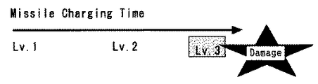
具体的には、制御部4は、○ボタン22cが押圧操作されたタイミングで○ボタン22cが連続的に押圧操作された時間のカウントを開始する。図6はミサイルピースの破壊力と○ボタン22cが押圧操作され続けた時間との関係を示す図なのであるが、この図6からわかるようにミサイルピースの破壊力は○ボタン22cが押圧操作され続けた時間に応じて、レベル1(Lv.1),レベル2(Lv.2),レベル3(Lv.3)等のように徐々に向上するようになっている。制御部4は、この○ボタン22cが押圧操作され続けた時間に応じてミサイルピースの破壊力を決定する。
【0051】
ただし、この○ボタン22cが押圧操作され続けた時間が所定時間を経過すると、キャラクタにより掴まれた状態でミサイルピースが爆発するようになっている。このため、制御部4は、○ボタン22cが押圧操作されたタイミングでカウントを開始した時間が所定の時間を経過した場合に、キャラクタにより掴まれているミサイルピースを爆発させる表示を行うように画像処理部5を表示制御する。
【0052】
このミサイルピースの爆発があると、キャラクタの動きが鈍くなり、或いはゲームオーバーになる等のように何らかのかたちでキャラクタにダメージが残るようになっている。このため、プレーヤは、ミサイルピースを持ち過ぎず、なおかつ、強力な破壊力が得られるように、○ボタン22cを押圧操作し続ける時間を調整しながらゲームを行うこととなる。
【0053】
なお、図6に示すようなレベルインジケータをモニタ装置7に表示して、プレーヤに対してミサイルピースの現在の破壊力を表示するようにしてもよい。
【0054】
次に、プレーヤは、上記直線L上に敵ピースが位置するようにキャラクタを移動操作し、ミサイルピースが適当な破壊力となったものと判断したタイミングで○ボタン22cを離間操作する。
【0055】
制御部4は、○ボタン22cが離間操作されると、それまでキャラクタにより掴まれていたミサイルピースがキャラクタの手を放れ、画像の中心を通って直線的に移動するように画像処理部5を表示制御する。
【0056】
図5(c)〜図5(e)は、このキャラクタの手から放れたミサイルピースが敵ピースに衝突するまでの様子を示す図なのであるが、この図5(c)〜図5(e)からわかるように、キャラクタ31により掴まれているミサイルピースであるオブジェクト30bは、プレーヤにより○ボタン22cが離間操作されたタイミングで図5(c)に示す画像30の中心Pを通り敵ピース30aに向かって直線的に移動表示される。そして、このミサイルピースであるオブジェクト30bが移動表示された直線上に敵ピース30aが位置した場合、図5(e)に示すようにこのオブジェクト30bが敵ピース30aに衝突表示される。
【0057】
当該ビデオゲームにおいては、敵ピース30aは画像の中心Pを通るようにキャラクタに向かって直線的に移動し、キャラクタに掴まれたミサイルピースも画像の中心Pを通るように直線的に移動する。このため、ミサイルピースを敵ピースに衝突させる照準合わせの操作は、キャラクタを周回移動操作するのみとすることができる。従って、複雑な照準合わせの操作を不要とすることができ、プレーヤの意識を画像全体とゲームに集中させることができる。
【0058】
ここで、ミサイルピースの破壊力は、○ボタン22cが押圧操作され続けた時間のみならず、ミサイルピースの大きさに応じても決定されるようになっており、ミサイルピースの大きさが大きくなるに連れて、その破壊力は、例えばレベル1(Lv.1),レベル2(Lv.2),レベル3(Lv.3)等のように徐々に向上するようになっている。
【0059】
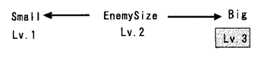
同様に、敵ピース30aの耐久力も、この敵ピース30aが形成された元となるオブジェクトの大きさに応じて決定されるようになっており、元となるオブジェクトの大きさが大きくなるに連れて、その耐久力は、例えば図7に示すようにレベル1(Lv.1),レベル2(Lv.2),レベル3(Lv.3)等のように徐々に向上するようになっている。
【0060】
次に、○ボタン22cが押圧操作され続けた時間及びミサイルピースの大きさに応じた破壊力のミサイルピースが敵ピースに向かって放たれることで、ミサイルピースが敵ピースに衝突した場合、○ボタン22cが押圧操作され続けた時間とミサイルピースの大きさとに応じたダメージが敵ピースに対して与えられることとなる。
【0061】
この結果、例えば敵ピースに衝突したミサイルピースの破壊力が敵ピースの耐久力を超過した場合にはミサイルピースにより敵ピースが破壊され、或いは敵ピースの動きが鈍くなり、また、ミサイルピースの破壊力が敵ピースの耐久力を下回った場合には、ミサイルピースに衝突した敵ピースが跳ね返り、或いは敵ピースがミサイルピースを突き抜けてキャラクタに衝突するようになっている。
【0062】
なお、キャラクタがミサイルピースを持った状態で敵ピースに衝突した場合、このミサイルピースが爆発し、キャラクタ及び敵ピースの双方が所定のダメージを受けるようになっている。
【0063】
上述の説明では、ミサイルピースは敵ピースに衝突すると爆発して敵ピースを破壊することとしたが、これは、ミサイルピースに不発弾を設け、この不発弾の場合には敵ピースは破壊されないようにしてもよい。
【0064】
また、敵ピースには目及び口の画像が付加され、キャラクタに向かって直線的に飛んでくることとしたが、これは、敵ピースに応じて様々な形相を付加し、この形相に応じて直線的のみならず曲線的等他の軌道で飛んでくるようにしてもよい。
【0065】
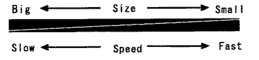
また、ミサイルピースの移動速度を、例えば図8に示すようにミサイルピースの大きさが大きくなるに連れて、その移動速度が遅くなる等のように、ミサイルピースの大きさ(面積)に応じて変化させるようにしてもよい。
【0066】
次に、このビデオゲームにおいては、ミサイルピースを敵ピースに衝突させるのみならず、以下のように敵ピースを撃退可能となっている。
【0067】
まず、図2に示すコントローラ10の例えば×ボタン22bが押圧操作されると、制御部4は、この×ボタン22bが押圧操作されたタイミングでキャラクタをジャンプ表示するように画像処理部5を制御する。これにより、プレーヤは、敵ピースがキャラクタに向かって飛んできたタイミングを見計らって×ボタン22bを押圧操作することで、飛んできた敵ピースをジャンプして避けることができる。なお、キャラクタがジャンプした際に、宙返り或いはクイックターン等を行うようにしてもよい。
【0068】
次に、図2に示すコントローラ10の例えば△ボタン22aが押圧操作されると、制御部4は、この△ボタン22aが押圧操作されている間、飛んできた敵ピースをキャラクタが掴むように画像処理部5を表示制御する。そして、制御部4は、△ボタン22aが離間操作されたタイミングで、この掴んだ敵ピースを投げ飛ばすように画像処理部5を表示制御する。これにより、キャラクタで敵ピースを投げ飛ばすことが可能となるため、ゲームをより面白いものとすることができる。
【0069】
[詳細なゲームの内容]
このゲームのゲーム内容をさらに詳細に説明すると、キャラクタに敵ピースが衝突すると、キャラクタは例えば1ポイントのダメージを受けるようになっている。キャラクタは、ダメージに応じてその表示形態が変化するようになっており、例えば敵ピースからダメージを受けた場合にはその表示形態が下等生物の表示形態に退化的に変化し、敵ピースにダメージを与えた場合にはその表示形態が高等生物の表示形態に進化的に変化するようになっている。
【0070】
一例ではあるが、このゲームの場合、キャラクタは、敵ピースから例えば3ポイントのダメージを受けると、その表示形態が1段階退化した表示形態で表示されるようになっている。また、キャラクタがダメージを受けることなく敵ピースを例えば5回連続的に破壊すると、その表示形態が1段階進化した表示形態で表示されるようになっている。
【0071】
そして、最終的に退化した表示形態において、敵ピースにより例えば3ポイントのダメージを受けるとゲームオーバーとなる。この逆に、例えばステージを形成する例えば2〜3分の映像の再生が終了した時点でキャラクタが生き残っていればゲームクリアとなる。
【0072】
制御部4は、図3のフローチャートのステップS6において、ビデオゲームがゲーム終了となったか否かを監視しており、ゲーム終了となっていない場合はステップS5に戻り上述のビデオゲームを続行制御し、ゲーム終了となった場合にはそのままこの図3のフローチャートに示す全ルーチンを終了する。
【0073】
[得点の計算]
次に、このビデオゲームにおいては、制御部4は、以下のように得点を計算するようになっている。
【0074】
まず、キャラクタが敵ピースを破壊する毎に所定の得点が加算される。この加算される得点は、面積が大きいミサイルピースを用いて敵ピースを破壊した場合には、上述のようにスピードの遅いミサイルピースで敵ピースを破壊したこととなり困難性が認められるため、高得点が加算されるようになっている。
【0075】
また、破壊力の大きなミサイルピースで敵ピースを破壊した場合には、上述のように破壊力をチャージし過ぎて爆発しないように○ボタン22cを連続的に押圧操作する必要があり困難性が認められるため、高得点が加算されるようになっている。
【0076】
また、キャラクタが敵ピースによりダメージを受けることなく、ミサイルピースにより敵ピースを連続して破壊するとやはり困難性が認められるため、高得点が加算されるようになっている。
【0077】
さらに、キャラクタが最終的な進化形態で表示されているときに敵ピースを破壊すると、例えば通常の2倍の得点が加算されるようになっている。なお、上述のように敵ピースから例えば3ポイントのダメージを受けると、キャラクタの表示形態が1段階退化した表示形態で表示されるようになっているのであるが、この最終的な進化形態で表示されているときに敵ピースから1回ダメージを受けると、この1回のダメージでその表示形態が1段階退化するようになっている(得点が2倍となる代わりに通常3回のダメージで1段階退化するのが、1回のダメージで1段階退化する。)。
【0078】
なお、敵ピースが破壊された際に所定のアイテムを残し、キャラクタがこのアイテムを取得した際に所定の得点が加算されるようにしてもよい。また、このアイテムとして、取得した際に得点が加算されるアイテムのみならず、逆に得点が減算されるアイテムを設けるようにしてもよい。
【0079】
[対戦プレー]
次に、以上の説明は、一つのキャラクタを一人のプレーヤで操作する一人プレー時の説明であったが、このビデオゲームにおいては、複数のキャラクタを複数のプレーヤで操作する複数プレーも可能となっている。
【0080】
図9に、この複数プレーの一例として二人プレー時における表示形態の一例を示す。この図9からわかるように、この二人プレー時においては、制御部4により、第1のプレーヤが操作するキャラクタ31、及び第2のプレーヤが操作するキャラクタ32が表示制御される。各キャラクタ31,32は、それぞれ画像30の周りの同じ円軌道上を時計回り方向及び反時計回り方向に周回移動可能となっている。各キャラクタ31,32がこの円軌道上で衝突すると、速度の遅いキャラクタが速度の速いキャラクタにより円軌道に沿って飛ばされるようになっている。なお、各キャラクタ31,32が円軌道上で衝突することなくすれ違うようにしてもよい。
【0081】
この二人プレー時においても、画像30から複数のオブジェクトが抽出され、この各オブジェクトが敵ピース35として、いずれかのキャラクタ31,32に向かって飛んでくるようになっている。各キャラクタ31,32の各プレーヤは、上述の一人プレー時と同様に、それぞれミサイルピースを敵ピースに衝突させて反撃する。そして、最終的に生き残った方(両者が生き残った場合は得点の高い方)がこのゲームの勝者となる。
【0082】
なお、この複数プレー時において、ミサイルピースを互いのキャラクタにぶつけ合うようにして対戦してもよい。
【0083】
[実施の形態の効果]
以上の説明から明らかなように、この実施の形態のビデオゲーム機は、動画像や静止画像等の画像に基づいてゲーム用のステージを形成することができる。このため、この実施の形態のビデオゲーム機は、プレーヤに対して常に新規なステージを提供することができ、プレーヤが繰り返しゲームを行うことにより、そのステージで次に起こる現象を憶え或いは予測してしまうような不都合を防止することができる。従って、この実施の形態のビデオゲーム機は、ゲームに対するプレーヤの慣れや飽きを防止することができ、いつまでも面白味が持続するゲームを提供することができる。
【0084】
なお、上述の実施の形態の説明は本発明の一例である。このため、上述の実施の形態の説明では、キャラクタは四角の画像外の円軌道上に沿って移動することとしたが、キャラクタを四角の画像内の円軌道上に沿って移動させるようにしてもよい。また、キャラクタを、四角の画像の外周に沿って四角状に移動させるようにしてもよい。或いは、画像を円状に表示し、キャラクタを、その画像の円周に沿って移動させるようにしてもよい。さらに、画像は、拡大,縮小,回転等をさせて表示するようにしてもよい。
【0085】
最後に、本発明は上述の実施の形態に限定されることはなく、本発明に係る技術的思想を逸脱しない範囲であれば、上述の実施の形態以外であっても設計等に応じて種々の変更が可能であることは勿論であることを付け加えておく。
【0086】
【発明の効果】
本発明は、プレーヤが作成し或いは選択した画像、さらには第三者から提供された画像に基づいてゲーム用のステージを形成することで、略々無限の形態のステージを提供することができるため、プレーヤに対して、面白くかつ飽きのこないビデオゲームを提供することができる。
【図面の簡単な説明】
【図1】本発明の実施の形態となるビデオゲーム機の簡略的なブロック図である。
【図2】上記実施の形態のビデオゲーム機に設けられているコントローラの斜視図である。
【図3】上記実施の形態のビデオゲーム機の全体的な動作の流れを示すフローチャートである。
【図4】上記実施の形態のビデオゲーム機の表示例を示す模式図である。
【図5】上記実施の形態のビデオゲーム機の他の表示例を示す模式図である。
【図6】上記実施の形態のビデオゲーム機において、キャラクタがミサイルピースを掴んでいる時間と、ミサイルピースの破壊力との関係を説明するための図である。
【図7】上記実施の形態のビデオゲーム機において、キャラクタが掴んだミサイルピースの大きさと、ミサイルピースの破壊力との関係を説明するための図である。
【図8】上記実施の形態のビデオゲーム機において、キャラクタが掴んだミサイルピースの大きさと、ミサイルピースの移動速度との関係を説明するための図である。
【図9】上記実施の形態のビデオゲーム機を複数のプレーヤで操作する場合の表示例を示す模式図である。
【符号の説明】
1…光ディスク,2…ディスクドライバ,3…通信部,4…制御部,5…画像処理部,6…表示制御部,7…モニタ装置,8…音声処理部,9…スピーカ装置,10…コントローラ,20R…把持部,20L…把持部,21…第1の操作部,22…第2の操作部,23R…アナログ操作部,23L…アナログ操作部,24…スタートボタン,25…セレクトボタン,26…モード選択スイッチ,27…発光ダイオード(LED),28…右ボタン,29…左ボタン,30…画像,30a…オブジェクト(敵ピース),30b…オブジェクト(ミサイルピース),30c…オブジェクト,31…キャラクタ,32…キャラクタ,35…オブジェクト(敵ピース),P…画像の中心(キャラクタの移動軌跡の中心),L…直線[0001]
BACKGROUND OF THE INVENTION
The present invention relates to an object forming method for forming a game stage based on an arbitrary image, an object forming program, a recording medium on which the object forming program is recorded, a gaming device, a gaming method, a gaming program, and a gaming program. The recorded recording medium.
[0002]
[Prior art]
Nowadays, video game machines capable of playing video games based on a game program recorded on a recording medium such as a CD-ROM, a DVD-ROM, or a semiconductor memory have become widespread.
[0003]
This video game machine reads a game program recorded on a recording medium such as the DVD-R in accordance with the operation of the player's controller, and displays a stage image and a character image corresponding to the game program on a monitor device. Enjoy playing video games.
[0004]
[Problems to be solved by the invention]
However, since the conventional video game is played on the stage created in advance by the manufacturer, if the video game is played repeatedly, the player will play the same stage many times. , Remember or predict the next event at that stage. For this reason, while the conventional video game is repeatedly played, the interest of the video game gradually fades and eventually gets bored by the player.
[0005]
The present invention has been made in view of the above-described problems. An object forming method and an object forming method that can prevent the player from getting used to and tired of the game by always providing a new stage to the player. It is an object of the present invention to provide a program, a recording medium on which an object formation program is recorded, a gaming device, a gaming method, a gaming program, and a recording medium on which a gaming program is recorded.
[0006]
[Means for Solving the Problems]
In order to solve the above-described problems, the present invention forms a game stage based on an image created or selected by a player, or an image provided by a third party. This makes it possible to provide a stage in an almost infinite form, so that the player can enjoy the game on many unknown stages, and can provide an interesting game that does not bore the player.
[0007]
DETAILED DESCRIPTION OF THE INVENTION
The present invention can be applied to a video game machine that enables a video game based on a game program recorded on a recording medium such as a DVD-ROM, a CD-ROM, or a semiconductor memory.
[0008]
[Video game console configuration]
FIG. 1 is a block diagram showing a configuration of a main part of a video game machine according to an embodiment of the present invention. As can be seen from FIG. 1, the video game machine according to the first embodiment has a
[0009]
In addition, the video game machine performs image processing on the image data read from the
[0010]
[Controller configuration]
FIG. 2 is a perspective view of the
[0011]
In addition, the
[0012]
The
[0013]
The
[0014]
The
[0015]
The
[0016]
The
[0017]
The
[0018]
Further, the
[0019]
The player operates these switches and buttons to play the following games.
[0020]
[Operation of video game console]
FIG. 3 is a flowchart showing the overall operation flow of the video game machine. The flowchart of FIG. 3 starts when the main power supply of the video game machine is turned on, and proceeds to step S1.
[0021]
In step S1, the
[0022]
In step S2, the
[0023]
The video game machine is connected to a playback device such as a personal computer device or a video camera device, and the image (still image or moving image) is captured from a recording medium such as a magnetic disk, a magneto-optical disk, a hard disk, or a semiconductor memory. May be performed.
[0024]
Next, in step S3, the
[0025]
FIG. 4A shows an example of this display image. As can be seen from FIG. 4A, the
[0026]
Next, in step S4, the contour of each object existing in the captured image is extracted, and an enemy piece that attacks the character is formed from one or a plurality of objects among the extracted objects. The
[0027]
Specifically, in the case of this video game, the contour line is chased and extracted according to changes in the original image (still image or moving image), and enemy characters are formed one after another to attack the character. . For this reason, since it is not preferable that a large number of objects are extracted from one image, a parameter for extracting a contour line is set. Based on this parameter, selective extraction from one image is performed. The objects are extracted.
[0028]
For example, when forming an enemy piece from a moving image, the
[0029]
Further, when forming an enemy piece from a still image, the
[0030]
The display image of each object and enemy piece is displayed on the
[0031]
The form of the enemy piece is such that the player can recognize at a glance that it is an enemy piece. Specifically, this is just an example. In this example, the
[0032]
Next, in step S5, the
[0033]
[Contents of video game]
Hereinafter, specific contents of the game will be described. As described above, the eyes and mouth are added to the
[0034]
Next, the
[0035]
This display is a display intended to show that the
[0036]
Next, at the timing when the luminance level of the
[0037]
In this example, the
[0038]
In addition, the
[0039]
Next, the player moves the
[0040]
As described above, in this example, the
[0041]
Further, the moving speed of the
[0042]
In this video game, a plurality of contour-extracted objects are successively made into enemy pieces and fly toward the character 31 (each part of one image is sequentially flying toward the character 31). 4), the player enjoys the game by tilting the
[0043]
Next, in the above description of the game content, the
[0044]
Specifically, as described above, one image is divided into a plurality of objects, and each object is sequentially turned into enemy pieces and flies toward the character as described above. When a character grabs an object that is not pieced, the object grabbed by the character becomes a missile piece. The missile piece can be shot down against the enemy piece flying toward the character to collide with the enemy piece.
[0045]
This will be described in more detail along with the above example. FIG. 5A shows a state in which the
[0046]
Next, when the
[0047]
Next, when the missile piece is gripped by the character as described above, the
[0048]
This straight line L indicates the direction in which the missile piece flies. If the
[0049]
Next, the missile piece, which is an object gripped by the character in this way, has a destructive force determined by the time and the size (area) of the object that the ○
[0050]
Specifically, the
[0051]
However, when the time during which the
[0052]
When this missile piece explodes, the character's movement becomes dull, or the character is damaged in some way, such as when the game is over. For this reason, the player plays the game while adjusting the time for which the
[0053]
A level indicator as shown in FIG. 6 may be displayed on the
[0054]
Next, the player moves the character so that the enemy piece is positioned on the straight line L, and moves the ○
[0055]
When the
[0056]
FIGS. 5 (c) to 5 (e) are diagrams showing how the missile piece released from the character's hand collides with an enemy piece. FIGS. 5 (c) to 5 (e). As can be seen from FIG. 5C, the
[0057]
In the video game, the
[0058]
Here, the destructive force of the missile piece is determined not only according to the time when the ○
[0059]
Similarly, the durability of the
[0060]
Next, when the missile piece collides with the enemy piece by releasing the missile piece with the destructive power according to the time during which the ○
[0061]
As a result, for example, when the destructive power of a missile piece that collides with an enemy piece exceeds the durability of the enemy piece, the enemy piece is destroyed by the missile piece, or the movement of the enemy piece becomes dull, and the missile piece is destroyed. When the strength falls below the durability of the enemy piece, the enemy piece that collided with the missile piece bounces back, or the enemy piece penetrates the missile piece and collides with the character.
[0062]
When a character collides with an enemy piece with a missile piece, the missile piece explodes, and both the character and the enemy piece receive predetermined damage.
[0063]
In the above description, when a missile piece collides with an enemy piece, it explodes and destroys the enemy piece, but this creates a missile piece in the missile piece so that the enemy piece will not be destroyed in the case of this missile bullet. It may be.
[0064]
In addition, an image of eyes and mouth is added to the enemy piece, and it will fly straight toward the character, but this adds various forms depending on the enemy piece, and according to this form You may make it fly not only in a straight line but also in other orbits such as a curved line.
[0065]
Also, according to the size (area) of the missile piece, for example, as shown in FIG. 8, the speed of the missile piece decreases as the size of the missile piece increases. It may be changed.
[0066]
Next, in this video game, not only the missile piece collides with the enemy piece, but the enemy piece can be repelled as follows.
[0067]
First, when, for example, the
[0068]
Next, when, for example, the
[0069]
[Detailed game contents]
The game content of this game will be described in more detail. When an enemy piece collides with the character, the character receives, for example, one point of damage. The display form of the character changes according to the damage. For example, when the damage is received from the enemy piece, the display form degenerates to the display form of the lower creature, When damage is given, the display form is evolutionarily changed to the display form of higher organisms.
[0070]
For example, in the case of this game, when a character receives, for example, 3 points of damage from an enemy piece, the character is displayed in a display form in which the display form is degenerated by one step. Further, when the enemy piece is destroyed five times continuously without taking damage, the display form is displayed in a display form evolved by one step.
[0071]
Then, in the finally degenerated display form, if the enemy piece receives, for example, 3 points of damage, the game is over. On the contrary, the game is cleared if, for example, the character survives at the time when the reproduction of, for example, 2-3 minutes of video forming the stage is completed.
[0072]
In step S6 of the flowchart of FIG. 3, the
[0073]
[Score calculation]
Next, in this video game, the
[0074]
First, a predetermined score is added each time a character destroys an enemy piece. The added score is that when an enemy piece is destroyed using a missile piece with a large area, the enemy piece was destroyed with a missile piece with a slow speed as described above. Is added.
[0075]
In addition, when an enemy piece is destroyed by a missile piece with a high destructive power, it is necessary to continuously press the ○
[0076]
Further, if the character is not damaged by the enemy piece, and the enemy piece is continuously destroyed by the missile piece, difficulty is recognized, so a high score is added.
[0077]
Further, when the enemy piece is destroyed while the character is displayed in the final evolution form, for example, a score twice as high as that of a normal character is added. As described above, when 3 points of damage are received from the enemy piece, the character display form is displayed in a display form that is degenerated by one step, but this final evolution form is displayed. If you take damage once from an enemy piece when it is being used, the display form will be degraded by one step with this damage (instead of doubling the score, you usually get 1 Degrading one step is degrading one step with a single damage.)
[0078]
A predetermined item may be left when the enemy piece is destroyed, and a predetermined score may be added when the character acquires this item. Further, as this item, not only the item to which the score is added when acquired, but also the item to which the score is subtracted may be provided.
[0079]
[Competitive play]
Next, the above explanation is for a single-player operation where one character is operated by a single player. However, in this video game, multiple play where multiple characters are operated by multiple players is also possible. ing.
[0080]
FIG. 9 shows an example of a display form during two-player play as an example of the multiple play. As can be seen from FIG. 9, during the two-player game, the
[0081]
Even during the two-player game, a plurality of objects are extracted from the
[0082]
In this multiplayer game, missile pieces may be played against each other.
[0083]
[Effect of the embodiment]
As is apparent from the above description, the video game machine of this embodiment can form a game stage based on images such as moving images and still images. For this reason, the video game machine of this embodiment can always provide a new stage to the player, and the player repeatedly plays the game to remember or predict the next phenomenon that will occur at that stage. Such inconveniences can be prevented. Therefore, the video game machine of this embodiment can prevent the player from getting used to and getting tired of the game, and can provide a game that continues to be interesting forever.
[0084]
The above description of the embodiment is an example of the present invention. For this reason, in the above description of the embodiment, the character moves along a circular orbit outside the square image, but the character is moved along a circular orbit in the square image. Also good. Further, the character may be moved in a square shape along the outer periphery of the square image. Alternatively, the image may be displayed in a circle and the character may be moved along the circumference of the image. Furthermore, the image may be displayed after being enlarged, reduced, rotated, or the like.
[0085]
Finally, the present invention is not limited to the above-described embodiment, and various modifications can be made depending on the design and the like, even if other than the above-described embodiment, as long as they do not depart from the technical idea according to the present invention. It is added that it is of course possible to change this.
[0086]
【The invention's effect】
Since the present invention forms a stage for a game based on an image created or selected by a player, or an image provided by a third party, it is possible to provide an almost infinite number of stages. It is possible to provide an interesting and timeless video game to the player.
[Brief description of the drawings]
FIG. 1 is a simplified block diagram of a video game machine according to an embodiment of the present invention.
FIG. 2 is a perspective view of a controller provided in the video game machine of the embodiment.
FIG. 3 is a flowchart showing an overall operation flow of the video game machine of the embodiment.
FIG. 4 is a schematic diagram showing a display example of the video game machine of the embodiment.
FIG. 5 is a schematic diagram showing another display example of the video game machine of the embodiment.
FIG. 6 is a diagram for explaining the relationship between the time during which a character is holding a missile piece and the destructive force of the missile piece in the video game machine of the embodiment.
FIG. 7 is a diagram for explaining the relationship between the size of a missile piece held by a character and the destructive force of the missile piece in the video game machine of the embodiment.
FIG. 8 is a diagram for explaining the relationship between the size of a missile piece held by a character and the movement speed of the missile piece in the video game machine of the embodiment.
FIG. 9 is a schematic diagram showing a display example when the video game machine of the embodiment is operated by a plurality of players.
[Explanation of symbols]
DESCRIPTION OF
Claims (21)
上記輪郭を抽出したオブジェクトに基づいて新たなオブジェクトを形成するステップと
を有するオブジェクト形成方法であって、
上記新たなオブジェクトを形成するステップは、上記輪郭抽出がなされたオブジェクトからキャラクタの障害を形成するステップを有することを特徴とする
オブジェクト形成方法。Extracting the contours of the objects constituting the image;
Forming a new object based on the object from which the contour is extracted ,
The object forming method, wherein the step of forming a new object includes the step of forming a character obstacle from the object from which the contour has been extracted .
上記画像は、動画像であり、
上記オブジェクトの輪郭を抽出するステップでは、固定値のパラメータに基づいて上記動画像の各オブジェクトの輪郭を抽出することを特徴とするオブジェクト形成方法。The object forming method according to claim 1,
The above image is a moving image,
In the object contour extracting step, the contour of each object of the moving image is extracted based on a fixed value parameter.
上記画像は、静止画像であり、
上記オブジェクトの輪郭を抽出するステップでは、パラメータの値を変化させながら上記静止画像の各オブジェクトの輪郭を抽出することを特徴とするオブジェクト形成方法。The object forming method according to claim 1,
The above image is a still image,
In the step of extracting the contour of the object, the contour of each object of the still image is extracted while changing a parameter value.
上記輪郭を抽出したオブジェクトに基づいて新たなオブジェクトを形成するステップとForming a new object based on the object from which the contour is extracted;
を有するオブジェクト形成方法であって、An object forming method comprising:
上記所定のパラメータは、上記輪郭を抽出するオブジェクトの数を特定するパラメータであることを特徴とするThe predetermined parameter is a parameter for specifying the number of objects from which the contour is extracted.
オブジェクト形成方法。Object formation method.
上記画像は動画像であり、The above image is a moving image,
上記所定のパラメータは、固定値であることを特徴とするオブジェクト形成方法。The object forming method, wherein the predetermined parameter is a fixed value.
上記画像は静止画像であり、The above image is a still image,
上記所定のパラメータは、時間の経過と共に変化する変数値であり、The predetermined parameter is a variable value that changes over time,
上記オブジェクトの輪郭を抽出するステップは、該パラメータの値を変化させながら上記静止画像の各オブジェクトの輪郭を抽出することを特徴とするオブジェクト形成方法。The step of extracting the contour of the object comprises extracting the contour of each object of the still image while changing the value of the parameter.
上記輪郭を抽出したオブジェクトに基づいて新たなオブジェクトを形成するステップとを、コンピュータに実行させるためのオブジェクト形成プログラムであって、
上記新たなオブジェクトを形成するステップにおいて、上記オブジェクトをキャラクタの障害とするステップを有することを特徴とする
オブジェクト形成プログラム。Extracting the contours of the objects constituting the image;
An object formation program for causing a computer to execute a step of forming a new object based on the object from which the contour is extracted ,
The object forming program characterized in that the step of forming the new object includes a step of making the object an obstacle of the character .
固定値のパラメータに基づいて、動画像の各オブジェクトの輪郭を抽出するステップを有することを特徴とするオブジェクト形成プログラム。The object forming program according to claim 7 ,
An object forming program comprising: extracting a contour of each object of a moving image based on a fixed value parameter.
パラメータの値を変化させながら静止画像の各オブジェクトの輪郭を抽出するステップを有することを特徴とするオブジェクト形成プログラム。The object forming program according to claim 7 ,
What is claimed is: 1. An object forming program comprising: extracting a contour of each object of a still image while changing a parameter value.
上記輪郭を抽出したオブジェクトに基づいて新たなオブジェクトを形成するステップとを、コンピュータに実行させるためのオブジェクト形成プログラムであって、An object forming program for causing a computer to execute a step of forming a new object based on the object from which the contour is extracted,
上記所定のパラメータは、上記輪郭を抽出するオブジェクトの数を特定するパラメータであることを特徴とするThe predetermined parameter is a parameter for specifying the number of objects from which the contour is extracted.
オブジェクト形成プログラム。Object formation program.
上記画像は動画像であり、The above image is a moving image,
上記所定のパラメータは、固定値であることを特徴とするオブジェクト形成プログラム。The object forming program, wherein the predetermined parameter is a fixed value.
上記画像は静止画像であり、The above image is a still image,
上記所定のパラメータは、時間の経過と共に変化する変数値であり、 The predetermined parameter is a variable value that changes over time,
上記オブジェクトの輪郭を抽出するステップは、該パラメータの値を変化させながら上記静止画像の各オブジェクトの輪郭を抽出することを特徴とするオブジェクト形成プログラム。The object forming program characterized in that the step of extracting the contour of the object extracts the contour of each object of the still image while changing the value of the parameter.
上記所定の画像からオブジェクトの輪郭を抽出する輪郭抽出手段と、
上記輪郭抽出手段で抽出されたオブジェクトに基づいてキャラクタの障害を形成する障害形成手段と、
上記障害形成手段で形成された障害をキャラクタに向けて移動表示する障害移動表示手段と、
上記キャラクタを移動操作するための操作手段と、
上記操作手段の操作に対応して上記表示手段上に表示されているキャラクタを移動表示するキャラクタ移動表示手段と
を有する遊技装置。Display control means for controlling display of a predetermined image and a predetermined character on the display means;
Contour extracting means for extracting the contour of the object from the predetermined image;
Obstacle formation means for forming the obstacle of the character based on the object extracted by the contour extraction means;
Obstacle movement display means for moving and displaying the obstacle formed by the obstacle formation means toward the character;
Operating means for moving the character;
A game apparatus comprising: character movement display means for moving and displaying a character displayed on the display means in response to an operation of the operation means.
上記所定の画像は動画像であり、
上記輪郭抽出手段は、固定値のパラメータに基づいて上記動画像の各オブジェクトの輪郭を抽出することを特徴とする遊技装置。A gaming device according to claim 15 , wherein
The predetermined image is a moving image,
The gaming machine characterized in that the contour extracting means extracts the contour of each object of the moving image based on a fixed value parameter.
上記所定の画像は静止画像であり、
上記輪郭抽出手段は、パラメータの値を変化させながら上記静止画像の各オブジェクトの輪郭を抽出することを特徴とする遊技装置。A gaming device according to claim 15 , wherein
The predetermined image is a still image,
The gaming machine characterized in that the contour extracting means extracts a contour of each object of the still image while changing a parameter value.
プレーヤにより上記操作手段の所定の操作がなされた際に、上記キャラクタの障害となるオブジェクト以外のオブジェクトをキャラクタに掴ませ、このキャラクタにより掴まれたオブジェクトを、プレーヤが上記操作手段を操作することで指示された方向に移動表示するオブジェクト移動表示手段を有することを特徴とする遊技装置。A gaming device according to any one of claims 15 to 17 ,
When the player performs a predetermined operation on the operation means, the character grasps an object other than the object that obstructs the character, and the player operates the operation means with the object grasped by the character. A gaming apparatus comprising object movement display means for moving and displaying in an instructed direction.
上記障害移動表示手段、及び上記オブジェクト移動表示手段は、画像の中心を通る直線に沿って上記障害となるオブジェクトを移動表示することを特徴とする遊技装置。A gaming device according to any one of claims 15 to 18 , comprising:
The obstacle movement display means and the object movement display means move and display the obstacle object along a straight line passing through the center of the image.
上記オブジェクト移動表示手段は、キャラクタにより掴まれたオブジェクトが移動する直線の表示を行うことを特徴とする遊技装置。A gaming device according to claim 19 ,
The game apparatus characterized in that the object movement display means displays a straight line along which an object held by a character moves.
上記オブジェクト移動表示手段は、キャラクタにより掴まれたオブジェクトの大きさに応じた速度で、該オブジェクトを移動表示することを特徴する遊技装置。A gaming device according to any one of claims 18 to 20 , wherein
The gaming machine characterized in that the object movement display means moves and displays the object at a speed corresponding to the size of the object held by the character.
Priority Applications (3)
| Application Number | Priority Date | Filing Date | Title |
|---|---|---|---|
| JP2001198853A JP3615501B2 (en) | 2000-11-09 | 2001-06-29 | Object forming method, object forming program, recording medium on which object forming program is recorded, and gaming apparatus |
| US10/039,747 US20020101423A1 (en) | 2000-11-09 | 2001-11-09 | Display control method |
| EP01309505A EP1205221A3 (en) | 2000-11-09 | 2001-11-09 | Display control method |
Applications Claiming Priority (3)
| Application Number | Priority Date | Filing Date | Title |
|---|---|---|---|
| JP2000342610 | 2000-11-09 | ||
| JP2000-342610 | 2000-11-09 | ||
| JP2001198853A JP3615501B2 (en) | 2000-11-09 | 2001-06-29 | Object forming method, object forming program, recording medium on which object forming program is recorded, and gaming apparatus |
Publications (2)
| Publication Number | Publication Date |
|---|---|
| JP2002208023A JP2002208023A (en) | 2002-07-26 |
| JP3615501B2 true JP3615501B2 (en) | 2005-02-02 |
Family
ID=26603701
Family Applications (1)
| Application Number | Title | Priority Date | Filing Date |
|---|---|---|---|
| JP2001198853A Expired - Fee Related JP3615501B2 (en) | 2000-11-09 | 2001-06-29 | Object forming method, object forming program, recording medium on which object forming program is recorded, and gaming apparatus |
Country Status (3)
| Country | Link |
|---|---|
| US (1) | US20020101423A1 (en) |
| EP (1) | EP1205221A3 (en) |
| JP (1) | JP3615501B2 (en) |
Families Citing this family (7)
| Publication number | Priority date | Publication date | Assignee | Title |
|---|---|---|---|---|
| US9566522B2 (en) * | 2005-05-27 | 2017-02-14 | Nokia Technologies Oy | Device, method, and computer program product for customizing game functionality using images |
| JP5039465B2 (en) * | 2007-07-24 | 2012-10-03 | 株式会社スクウェア・エニックス | GAME PROGRAM, STORAGE MEDIUM, AND GAME MACHINE |
| JP5558730B2 (en) * | 2009-03-24 | 2014-07-23 | 株式会社バンダイナムコゲームス | Program and game device |
| JP5827007B2 (en) * | 2010-10-15 | 2015-12-02 | 任天堂株式会社 | Game program, image processing apparatus, image processing system, and image processing method |
| US9694282B2 (en) | 2011-04-08 | 2017-07-04 | Disney Enterprises, Inc. | Importing audio to affect gameplay experience |
| US20160023114A1 (en) * | 2013-03-11 | 2016-01-28 | Square Enix Co., Ltd. | Video game processing apparatus and video game processing program product |
| US20200043031A1 (en) * | 2018-08-01 | 2020-02-06 | Activision Publishing, Inc. | Systems and Methods for Generating and Executing Online Interactive Multimedia Challenges During Online Transactions |
Family Cites Families (17)
| Publication number | Priority date | Publication date | Assignee | Title |
|---|---|---|---|---|
| US4710873A (en) * | 1982-07-06 | 1987-12-01 | Marvin Glass & Associates | Video game incorporating digitized images of being into game graphics |
| US5357604A (en) * | 1992-01-30 | 1994-10-18 | A/N, Inc. | Graphics processor with enhanced memory control circuitry for use in a video game system or the like |
| US5553864A (en) * | 1992-05-22 | 1996-09-10 | Sitrick; David H. | User image integration into audiovisual presentation system and methodology |
| WO1995017934A1 (en) * | 1993-12-27 | 1995-07-06 | Kabushiki Kaisha Ace Denken | Image displaying game machine and image display controlling method |
| US5498003A (en) * | 1993-10-07 | 1996-03-12 | Gechter; Jerry | Interactive electronic games and screen savers with multiple characters |
| US5595389A (en) * | 1993-12-30 | 1997-01-21 | Eastman Kodak Company | Method and apparatus for producing "personalized" video games using CD discs |
| US6283858B1 (en) * | 1997-02-25 | 2001-09-04 | Bgk International Incorporated | Method for manipulating images |
| AU2802097A (en) * | 1997-04-15 | 1998-11-11 | Criticom Corporation | Computer games having optically acquired images which are combined with computergenerated graphics and images |
| GB9712724D0 (en) * | 1997-06-18 | 1997-08-20 | Holmes Steven | Method and apparatus for interaction with broadcast television content |
| JPH1133230A (en) * | 1997-07-16 | 1999-02-09 | Sega Enterp Ltd | Communication game system |
| JP3372832B2 (en) * | 1997-07-25 | 2003-02-04 | コナミ株式会社 | GAME DEVICE, GAME IMAGE PROCESSING METHOD, AND COMPUTER-READABLE RECORDING MEDIUM CONTAINING GAME IMAGE PROCESSING PROGRAM |
| JPH11144040A (en) * | 1997-11-05 | 1999-05-28 | Nintendo Co Ltd | Portable game machine and cartridge for portable game machine |
| JPH11154240A (en) * | 1997-11-20 | 1999-06-08 | Nintendo Co Ltd | Image producing device to produce image by using fetched image |
| JP2939230B1 (en) * | 1998-03-05 | 1999-08-25 | 株式会社ナムコ | Image generation device and information storage medium |
| JP4045024B2 (en) * | 1998-04-24 | 2008-02-13 | 富士フイルム株式会社 | Image capture device and method |
| TW541193B (en) * | 1998-06-01 | 2003-07-11 | Sony Computer Entertainment Inc | Portable electronic machine and entertaining system |
| US6435969B1 (en) * | 1998-11-03 | 2002-08-20 | Nintendo Co., Ltd. | Portable game machine having image capture, manipulation and incorporation |
-
2001
- 2001-06-29 JP JP2001198853A patent/JP3615501B2/en not_active Expired - Fee Related
- 2001-11-09 US US10/039,747 patent/US20020101423A1/en not_active Abandoned
- 2001-11-09 EP EP01309505A patent/EP1205221A3/en not_active Withdrawn
Also Published As
| Publication number | Publication date |
|---|---|
| EP1205221A3 (en) | 2004-04-14 |
| JP2002208023A (en) | 2002-07-26 |
| EP1205221A2 (en) | 2002-05-15 |
| US20020101423A1 (en) | 2002-08-01 |
Similar Documents
| Publication | Publication Date | Title |
|---|---|---|
| US6280323B1 (en) | Device, method and storage medium for displaying penalty kick match cursors in a video soccer game | |
| US20110053688A1 (en) | Entertainment system providing dynamically augmented game surfaces for interactive fun and learning | |
| JP5057715B2 (en) | GAME CONTROL PROGRAM, GAME CONTROL METHOD, AND GAME DEVICE | |
| JP2007296108A (en) | Video game processing device, video game processing method, and video game processing program | |
| JP5323881B2 (en) | GAME DEVICE AND GAME CONTROL PROGRAM | |
| JP2011087869A (en) | Generating system and generating method for behavior control data, information processor, control method for information processor, and program | |
| JP3495029B2 (en) | Command processing program, recording medium recording command processing program, command processing apparatus and method | |
| JP4110186B2 (en) | GAME PROGRAM, GAME DEVICE, AND GAME CONTROL METHOD | |
| JP3892889B1 (en) | GAME PROGRAM, GAME DEVICE, AND GAME CONTROL METHOD | |
| JP3615501B2 (en) | Object forming method, object forming program, recording medium on which object forming program is recorded, and gaming apparatus | |
| KR100829681B1 (en) | Ball paddle game device | |
| JP2001321567A (en) | Computer readable recording medium recording program of ball based game and device and method of ball based game | |
| JP2003190636A (en) | Video game program, readable recording medium on which video game program is recorded, method, and video game device | |
| WO2007135867A1 (en) | Game program, game device, and game control method | |
| JP4191768B2 (en) | GAME PROGRAM, GAME DEVICE, AND GAME CONTROL METHOD | |
| JP4205118B2 (en) | GAME PROGRAM, GAME DEVICE, AND GAME CONTROL METHOD | |
| JP3750103B2 (en) | Recording medium and game device | |
| JP4482017B2 (en) | GAME PROGRAM, GAME DEVICE, AND GAME CONTROL METHOD | |
| JP2007167117A (en) | Game program, game device, and method for controlling game | |
| JP2008142219A (en) | Game program, game apparatus and game control method | |
| JP5008646B2 (en) | GAME PROGRAM, GAME DEVICE, AND GAME CONTROL METHOD | |
| JP4191769B2 (en) | GAME PROGRAM, GAME DEVICE, AND GAME CONTROL METHOD | |
| JP5044610B2 (en) | GAME PROGRAM, GAME DEVICE, GAME CONTROL METHOD | |
| JP2001149648A (en) | Sport game device | |
| WO2023063121A1 (en) | Computer program, game system used in same, and control method |
Legal Events
| Date | Code | Title | Description |
|---|---|---|---|
| A131 | Notification of reasons for refusal |
Free format text: JAPANESE INTERMEDIATE CODE: A131 Effective date: 20040706 |
|
| A521 | Request for written amendment filed |
Free format text: JAPANESE INTERMEDIATE CODE: A523 Effective date: 20040906 |
|
| TRDD | Decision of grant or rejection written | ||
| A01 | Written decision to grant a patent or to grant a registration (utility model) |
Free format text: JAPANESE INTERMEDIATE CODE: A01 Effective date: 20041026 |
|
| A61 | First payment of annual fees (during grant procedure) |
Free format text: JAPANESE INTERMEDIATE CODE: A61 Effective date: 20041029 |
|
| R150 | Certificate of patent or registration of utility model |
Free format text: JAPANESE INTERMEDIATE CODE: R150 |
|
| FPAY | Renewal fee payment (event date is renewal date of database) |
Free format text: PAYMENT UNTIL: 20081112 Year of fee payment: 4 |
|
| FPAY | Renewal fee payment (event date is renewal date of database) |
Free format text: PAYMENT UNTIL: 20091112 Year of fee payment: 5 |
|
| FPAY | Renewal fee payment (event date is renewal date of database) |
Free format text: PAYMENT UNTIL: 20091112 Year of fee payment: 5 |
|
| FPAY | Renewal fee payment (event date is renewal date of database) |
Free format text: PAYMENT UNTIL: 20101112 Year of fee payment: 6 |
|
| FPAY | Renewal fee payment (event date is renewal date of database) |
Free format text: PAYMENT UNTIL: 20111112 Year of fee payment: 7 |
|
| FPAY | Renewal fee payment (event date is renewal date of database) |
Free format text: PAYMENT UNTIL: 20121112 Year of fee payment: 8 |
|
| FPAY | Renewal fee payment (event date is renewal date of database) |
Free format text: PAYMENT UNTIL: 20121112 Year of fee payment: 8 |
|
| FPAY | Renewal fee payment (event date is renewal date of database) |
Free format text: PAYMENT UNTIL: 20131112 Year of fee payment: 9 |
|
| LAPS | Cancellation because of no payment of annual fees |