JP3614912B2 - Engine combustion control device - Google Patents
Engine combustion control device Download PDFInfo
- Publication number
- JP3614912B2 JP3614912B2 JP00753195A JP753195A JP3614912B2 JP 3614912 B2 JP3614912 B2 JP 3614912B2 JP 00753195 A JP00753195 A JP 00753195A JP 753195 A JP753195 A JP 753195A JP 3614912 B2 JP3614912 B2 JP 3614912B2
- Authority
- JP
- Japan
- Prior art keywords
- amount
- ignition timing
- cylinder
- engine
- fuel ratio
- Prior art date
- Legal status (The legal status is an assumption and is not a legal conclusion. Google has not performed a legal analysis and makes no representation as to the accuracy of the status listed.)
- Expired - Fee Related
Links
Images


Classifications
-
- F—MECHANICAL ENGINEERING; LIGHTING; HEATING; WEAPONS; BLASTING
- F02—COMBUSTION ENGINES; HOT-GAS OR COMBUSTION-PRODUCT ENGINE PLANTS
- F02P—IGNITION, OTHER THAN COMPRESSION IGNITION, FOR INTERNAL-COMBUSTION ENGINES; TESTING OF IGNITION TIMING IN COMPRESSION-IGNITION ENGINES
- F02P5/00—Advancing or retarding ignition; Control therefor
- F02P5/04—Advancing or retarding ignition; Control therefor automatically, as a function of the working conditions of the engine or vehicle or of the atmospheric conditions
- F02P5/145—Advancing or retarding ignition; Control therefor automatically, as a function of the working conditions of the engine or vehicle or of the atmospheric conditions using electrical means
- F02P5/15—Digital data processing
- F02P5/1502—Digital data processing using one central computing unit
-
- F—MECHANICAL ENGINEERING; LIGHTING; HEATING; WEAPONS; BLASTING
- F02—COMBUSTION ENGINES; HOT-GAS OR COMBUSTION-PRODUCT ENGINE PLANTS
- F02D—CONTROLLING COMBUSTION ENGINES
- F02D37/00—Non-electrical conjoint control of two or more functions of engines, not otherwise provided for
- F02D37/02—Non-electrical conjoint control of two or more functions of engines, not otherwise provided for one of the functions being ignition
-
- F—MECHANICAL ENGINEERING; LIGHTING; HEATING; WEAPONS; BLASTING
- F02—COMBUSTION ENGINES; HOT-GAS OR COMBUSTION-PRODUCT ENGINE PLANTS
- F02P—IGNITION, OTHER THAN COMPRESSION IGNITION, FOR INTERNAL-COMBUSTION ENGINES; TESTING OF IGNITION TIMING IN COMPRESSION-IGNITION ENGINES
- F02P5/00—Advancing or retarding ignition; Control therefor
- F02P5/04—Advancing or retarding ignition; Control therefor automatically, as a function of the working conditions of the engine or vehicle or of the atmospheric conditions
- F02P5/045—Advancing or retarding ignition; Control therefor automatically, as a function of the working conditions of the engine or vehicle or of the atmospheric conditions combined with electronic control of other engine functions, e.g. fuel injection
-
- Y—GENERAL TAGGING OF NEW TECHNOLOGICAL DEVELOPMENTS; GENERAL TAGGING OF CROSS-SECTIONAL TECHNOLOGIES SPANNING OVER SEVERAL SECTIONS OF THE IPC; TECHNICAL SUBJECTS COVERED BY FORMER USPC CROSS-REFERENCE ART COLLECTIONS [XRACs] AND DIGESTS
- Y02—TECHNOLOGIES OR APPLICATIONS FOR MITIGATION OR ADAPTATION AGAINST CLIMATE CHANGE
- Y02T—CLIMATE CHANGE MITIGATION TECHNOLOGIES RELATED TO TRANSPORTATION
- Y02T10/00—Road transport of goods or passengers
- Y02T10/10—Internal combustion engine [ICE] based vehicles
- Y02T10/40—Engine management systems
Landscapes
- Engineering & Computer Science (AREA)
- Chemical & Material Sciences (AREA)
- Combustion & Propulsion (AREA)
- Mechanical Engineering (AREA)
- General Engineering & Computer Science (AREA)
- Theoretical Computer Science (AREA)
- Signal Processing (AREA)
- Electrical Control Of Air Or Fuel Supplied To Internal-Combustion Engine (AREA)
- Combined Controls Of Internal Combustion Engines (AREA)
- Electrical Control Of Ignition Timing (AREA)
Description
【0001】
【産業上の利用分野】
本発明は、例えばO2 センサを用いてフィードバック制御を行うようにしたエンジンの運転制御装置に関する。
【0002】
【従来の技術】
従来、例えば船外機用2サイクルエンジンでは、O2 センサにより空燃比を検出し、該検出空燃比が目標空燃比となるよう燃料供給量を制御するようにしたO2 フィードバック制御を行い、エンジン性能の向上を図ることが行われている。
【0003】
このようなO2 フィードバック制御を行う場合、通常、上記目標空燃比は、排気ガス量の軽減,燃費向上等の目的から安定した燃焼が得られる範囲において可能な限りリーン側に設定される。
【0004】
【発明が解決しようとする課題】
ここで一般にエンジンは、図2に実線で示すように、空燃比がリッチ側,又はリーン側に所定範囲を越えて移行するとエンジン回転数は減少するという特性を有している。
【0005】
そのため、例えば目標空燃比を上記所定範囲の境界値a付近に設定して上述のO2 フィードバック制御を行った場合、検出空燃比が上記目標空燃比aを中心に例えばb〜cの間で変動すると、この検出空燃比の変動に応じて燃料供給量が可変制御され、上記目標空燃比aに保持される。ところが、この場合燃料供給量が変化することから、エンジン回転数がd〜eの間で変動することとなる。
【0006】
このことは、上記船外機用2サイクルエンジンを備えたモータボートにおいては、スロットル開度を一定にしたトロール運転域においてエンジン回転数が増減するという不快な問題を生じる。
【0007】
また、複数の気筒を備えるエンジンにおいては、各気筒毎に吸入空気量に差が生じる場合があり、この気筒毎の吸入空気量の差に起因してエンジン回転数が増減するという問題が発生する。
【0008】
また一方、船外機のように排気ガスを水中に排出することから背圧が発生するエンジンでは、この背圧の変化によってエンジンの吸入空気量が変動し、この点からもエンジン回転数が増減するという問題が発生する。
【0009】
本発明は上記問題に鑑みてなされたもので、空燃比が目標空燃比となるように燃料供給量をフィードバック制御した場合の、エンジン回転数の変動を防止できるエンジンの燃焼制御装置を提供することを目的としている。
【0010】
【課題を解決するための手段】
図10に示すように、請求項1の発明に係るエンジンの燃焼制御装置は、複数の気筒を備え、該各気筒の排気通路を共通の集合排気通路に接続し、各気筒の有効排気管長が異なる構造を有するエンジンの燃焼制御装置において、各気筒の吸入空気量を求める吸入空気量検出手段と、空燃比を検出する空燃比検出センサと、該検出された空燃比が目標空燃比に収斂するよう燃料供給量を増減する燃料供給量制御手段と、上記検出された空燃比に基づいて、上記燃料供給量の増減によるエンジン回転数の変動が縮小するよう点火時期を制御する点火時期制御手段と、該点火時期制御手段による点火時期を、吸入空気量の多い気筒の点火進角量が吸入空気量の少ない気筒の点火進角量より小さくなるように補正して各気筒毎の点火時期を求める点火時期補正手段とを備えたことを特徴としている。
【0013】
請求項2の発明に係るエンジンの燃焼制御装置は、請求項1において、上記エンジンが水中に排気ガスを排出するように構成されており、背圧を検出する背圧検出手段36を備え、上記点火時期補正手段59が上記背圧をパラメータとして点火時期を補正するように構成されていることを特徴としている。
【0014】
【作用】
請求項1の発明によれば、空燃比検出センサ35によりエンジンの空燃比が検出され、この検出値に基づいて燃料供給量制御手段56によりエンジンへの燃料供給量が制御されるとともに、点火時期制御手段57によりエンジンの点火時期が制御される。
【0015】
このように、検出空燃比に基づいて燃料供給量とエンジンの点火時期とを制御するようにしたので、燃料供給量の増減によるエンジン回転数の変動が点火時期の制御により吸収され、エンジン回転数を安定させることができる。
【0016】
また、点火時期制御手段57によるエンジンの点火時期が、点火時期補正手段59により、吸入空気量の変化を表すパラメータに基づいて補正される。
【0017】
このように、エンジンの点火時期を吸入空気量の変化に応じて制御するようにしたので、吸入空気量の変動によるエンジン回転数の増減を回避することができる。
【0018】
また、吸入空気量検出手段58により各気筒毎の吸入空気量が求められ、上記空燃比に基づいて設定された点火時期が、点火時期補正手段59により、各気筒の特性に起因する吸入空気量のばらつきに基づいて補正され、各気筒に対応した点火時期が求められる。
【0019】
このように、集合排気方式を採用したことによる各気筒毎の吸入空気量のばらつきに基づいて各気筒の点火時期を制御するようにしたので、各気筒毎に吸入空気量が異なる場合においても各気筒の出力の差異を軽減し、エンジン回転数の変動を防止することができる。
【0020】
請求項2の発明では、点火時期制御手段57による点火時期を点火時期補正手段59により背圧の変化に基づいて補正するようにしたので、背圧の変化に起因するエンジン回転数の変動を防止することができる。
【0021】
【実施例】
以下、本発明の実施例を図に基づいて説明する。
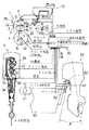
図1ないし図10は、本発明の一実施例によるエンジンの燃焼制御装置を説明するための図であり、図1は本装置が適用された船外機用2サイクルエンジンの概略構成図、図2は空燃比と回転数との相関関係を示す図、図3はO2 フィードバック制御時の時間に対する燃料噴射量と点火時期との相関関係を示す図、図4は進角補正量と回転数の上昇量との相関関係を示す図、図5は吸入空気量と進角補正量との相関関係を示す図、図6は背圧と吸入空気量との相関関係を示す図、図7は背圧と進角補正量との相関関係を示す図、図8は気筒数による回転数と吸入空気量との相関関係を示す図、図9は上記実施例装置の動作を説明するためのフローチャート図、図10は上記実施例装置のクレーム構成図である。
【0022】
図1において、1は船外機用2サイクルクランク軸縦置3気筒エンジンであり、これはシリンダブロック2のシリンダボア3a内にピストン3を摺動自在に挿入配置し、該ピストン3をコンロッド4でクランク軸5に連結した構造のものである。なお、A−A断面中、▲1▼〜▲3▼は気筒番号を示しており、上記エンジン1は、上記各気筒▲1▼〜▲3▼の排気ポートを集合排気管54に連通した集合排気構造を有しており、各気筒▲1▼,▲2▼,▲3▼は上段,中段,下段に位置していることから排気管の有効管長が異なり、各気筒への吸入空気量とエンジン回転速度との関係は図8に示すように各々異なる特性を有する。
【0023】
上記シリンダブロック2の合面にはシリンダヘッド6が装着されており、該シリンダヘッド6に形成された燃焼凹部内には点火プラグ7が挿入されている。なお、2aは排気ポート,2bは掃気ポートである。
【0024】
また上記実施例エンジン1は各種のセンサを備えている。即ち、上記シリンダヘッド6には筒内圧を測定するための圧力センサ31が、シリンダブロック2にはエンジン温度検出センサ37が、上記クランク軸5にはクランク角度(エンジン回転数)を検出するための角度センサ33が、またクランク室8には吸気温または機関の温度を測定するための温度センサ32及びクランク室内圧を測定するための圧力センサ34が、さらにまた排気膨張管には背圧を検出するための背圧センサ36がそれぞれ装着されている。
【0025】
また▲1▼番気筒と▲2▼番気筒との排気ポート2aより燃焼室寄り部分同士はバイパス通路40で連通されており、該通路40の途中部分に、既燃ガスの空燃比を検出するためのO2 センサ(空燃比検出センサ)35が接続されている。なお、一般に2サイクルエンジンの場合には新気吹き抜けの現象があり、このため導入された新気の一部が燃焼ガスとともに排出されるので、従来のようにO2 センサを単に排気管に取り付けるだけでは正確な空燃比を検出できなかった。本実施例では、上述のバイパス通路40にO2 センサを配置したので、正確な空燃比を検出できる。
【0026】
なお、上記O2 センサは、▲1▼番気筒の燃焼室近傍から取り出した導入パイプの先端に取付けても良い。
【0027】
上記各気筒のクランク室8には各吸気通路10がシリンダボア3aを介して又は直接連通するようにそれぞれ接続されている。該各吸気通路10のクランク室側開口近傍には、吸気の逆流を防止するためのリードバルブ11が配設されている。また上記各吸気通路10には該吸気通路内に燃料を噴射するためのインジェクタ12が装着されており、該インジェクタ12には燃料供給装置13が接続されている。なお、インジェクタを全気筒共通としてもよい。この場合には吸気マニホールドの集合部に設けることになる。また上記吸気通路10内にはスロットルバルブ15が配設されており、該スロットルバルブ15の回動量すなわちスロットル角はセンサ41により検出されるようになっている。さらに船外機本体50には、トリム角βを検出するためのトリム角検出センサ42が設けられている。なお、55は上記船外機本体50が取り付けられる船体を示している。
【0028】
上記エンジン1は制御部としてのECU30を備えている。該ECU30には、上記筒内圧検出センサ31,吸気温検出センサ32,クランク角度検出センサ33,クランク室内圧検出センサ34,O2 センサ35,背圧検出センサ36,エンジン温度検出センサ37,スロットル角検出センサ41,トリムスイッチ51,マウント高さ検出センサ52,大気圧検出センサ,シフトスイッチ,冷却水温度検出センサ,及びエンジン振動センサの各検出信号が入力されている。またECU30の出力制御信号は、上記点火プラグ7,インジェクタ12,及びトリム角調節装置53にそれぞれ入力されている。
【0029】
ここで、本実施例のECU30は、検出空燃比が目標空燃比よりリーン側にある場合には点火時期を進角側に補正する。そしてこの点火時期の進角値は、吸入空気量を表すパラメータによって補正される。例えば図4に示すように、点火時期を進角するとエンジン回転数は増大するが、この上昇量は特性線A,B,Cに示すように、吸入空気量が増加するに伴って増大する傾向を備えている。このことから、図5に示すように、吸入空気量が小さいほど上記進角補正量を大きくし、逆に吸入空気量が大きいほど上記進角補正量を小さく設定することが必要である。
【0030】
一方、図6に示すように、背圧の増大に伴って吸入空気量は減少することから、本実施例では、図7に示すように、背圧の増加に伴って進角補正量を大きく設定しており、上記ECU30には図5に対応するマップが格納されている。
【0031】
また、本実施例エンジンのように3つの気筒▲1▼〜▲3▼を集合排気管に接続した場合、各気筒への吸入空気量は図8に示すように差異があり、しかもエンジン回転数の増加に伴って異なる傾向をもって変化する。そこで本実施例では、図8に示す各気筒毎の吸入空気量のばらつき傾向に伴って点火進角量を補正する。即ち、吸入空気量の多い気筒の点火進角量を吸入空気量の少ない気筒の点火進角量より小さく制御する。
【0032】
次に本実施例の作用効果について説明する。
本実施例においては、既燃ガスの空燃比に応じて燃料噴射量,及び点火時期の進角制御を行うが、この進角値を吸入空気量を表すパラメータに応じてさらに補正する。
【0033】
まず、上記燃料供給量,点火時期の進角制御を図3に基づいて詳細に説明する。まず、目標空燃比を図2のaに設定した場合、上記エンジン1の既燃ガスの空燃比は図3(a)に示すように時間tの経過に伴ってλ=1(A/F=a)を基準としてリーン側とリッチ側との間で変動することとなる。この変動に応じて図3(b)に示すように上記O2 センサ35から目標値よりリッチ,リーンであることを示す大,小の検出値が出力される。
【0034】
すると本実施例では、上記検出値の変化に同期させて燃料噴射量を図3(c)に示すように制御する。即ち、上記空燃比がリッチ側からリーン側に変化すると、燃料噴射量を所定値fに設定するとともに、一定の割合で増加させる。これにより、上記空燃比がリッチ方向に制御される。また、上記空燃比がリーン側からリッチ側に変化すると、燃料噴射量を所定値gに設定するとともに、一定の割合いで減少させる。これにより、上記空燃比がリーン方向に制御される。
【0035】
ここで、本実施例では目標空燃比をできる限りリーン側のA/F=aに設定しているので、上記検出空燃比がaよりさらにリーン側になるとエンジン回転数は図2に示すように低下することとなる。そのためそのままではエンジン回転数は図3(d)に破線で示すように減少する。そこで本実施例では、上記検出空燃比が目標値aよりリーン側にある場合には、図3(e)に示すように、点火時期を進角側に制御するようにしている。これにより、上記エンジン回転数が図3(d)の目標rpmに安定化される。この場合、図3(e)の実線D,一点鎖線Eで示すように吸入空気量が多いほど上記空燃比に基づく進角量を小さくする。
【0036】
次に、上記点火時期の進角量の補正制御を図4〜9に基づいて詳細に説明する。
まず、上記ECU30により、背圧,エンジン回転数,スロットル開度(エンジン負荷),気筒番号,フィードバック信号等の各データが読み込まれ、フィードバック信号に基づいて燃料噴射量が演算される(ステップS1,S2)。
【0037】
また、上記エンジン回転数,負荷に基づいて基本マップから基本点火時期が設定されるとともに、上記燃料噴射量(あるいはフィードバック信号)に基づいて点火時期の進角値が演算される(ステップS3,S4)。
【0038】
そして、上記進角値の補正値が、吸入空気量を表すパラメータに基づいて求められ、最終進角値が求められ、点火時期がこの最終進角値に補正制御される(ステップS5,S6)。
【0039】
ここで上記吸入空気量を表すパラメータとして、例えば背圧,気筒番号が採用できる。図6,図7に示すように背圧が大きいほど吸入空気量は少なくなるので、背圧が大きいほど上記進角値はより進角側に補正される。これにより背圧が大きいことに起因して吸入空気量が少なくなることによるエンジン回転数の低下が補われ、その結果エンジン回転数が一定に保持される。
【0040】
また、上記気筒番号▲1▼〜▲3▼においては、図8に示すように、エンジン回転数の増加に伴って上段の♯1気筒▲1▼では吸入空気量が減少するのに対し、下段の♯3気筒▲3▼では吸入空気量は増大し、また中段の♯2気筒▲2▼ではあまり変化しない傾向がある。このことから本実施例では、例えば3000rpmにおいては、吸入空気量の最も多い♯1気筒▲1▼の進角補正量を最小に、吸入空気量の最も小さい♯3気筒▲3▼の進角補正量を最大に、♯2気筒▲2▼の進角補正量をその中間に設定している。そしてエンジン回転数の増加に伴って吸入空気量が増加するほど進角補正量を小さくし、空気量が減少するほど進角補正量を大きくしている。その結果本実施例では、吸入空気量の異なる全ての気筒▲1▼〜▲3▼を目標回転数に制御でき、エンジン回転数の変動を防止することができる。
【0041】
以上のように、本実施例では、検出空燃比に基づいて燃料供給量をフィードバック制御するとともに、点火時期を進角制御するようにしたのでスロットル開度を一定に保持していながらエンジン回転数が変動するのを防止でき、もってエンジン回転数の安定化を図ることができる。
【0042】
即ち、図2に示すように、回転数が減少する空燃比a〜cの範囲で点火時期を進角させて回転数をdまで上昇させることにより、空燃比がb〜cの間で変動した場合でも、エンジン回転数をdの値に略一定に維持できることとなる。なお、図2の一点鎖線は、上記同一スロットル開度において点火時期を進角させた場合の特性を示しており、空燃比がcのときの回転数がeからdに上昇していることがわかる。
【0043】
なお、上記実施例では、図2に示すように、目標空燃比をリーン側のaに設定した場合について説明したが、本発明は、急加速時の加速性を向上する目的等から上記目標空燃比をリッチ側の例えばhに設定した場合にも適用できる。この場合、検出空燃比が目標値hよりさらにリッチ側に変動したときに、点火時期を進角して回転数を上昇させる制御を行うこととなり、このように上記空燃比をリッチ側に設定した場合でも回転数の変動を抑制することができる。
【0044】
【発明の効果】
以上のように請求項1の発明によれば、検出空燃比に基づいて燃料供給量と共に点火時期を制御するようにしたので、目標空燃比をリーン側,あるいはリッチ側に設定した場合のエンジン回転数の安定化を図ることができる効果がある。
【0045】
また、点火時期の進角量を、吸入空気量の変化を表すパラメータに基づいて補正するようにしたので、エンジン回転数をより一層安定化できる効果がある。
【0046】
また、請求項2の発明によれば、背圧の変化に基づいて上記進角量を補正するようにしたので、背圧の発生する船外機等のエンジンにおいても回転数の安定化を図ることができる効果がある。
【図面の簡単な説明】
【図1】本発明の一実施例によるエンジンの燃焼制御装置が適用された船外機用2サイクルエンジンの概略構成図である。
【図2】上記実施例装置における空燃比と回転数との相関関係を示す図である。
【図3】上記実施例装置のO2 フィードバック制御時の燃料噴射量と点火時期との相関関係を示す図である。
【図4】上記実施例装置の進角補正量と回転数の上昇量との相関関係を示す図である。
【図5】上記実施例装置の吸入空気量と進角補正量との相関関係を示す図である。
【図6】上記実施例装置の背圧と吸入空気量との相関関係を示す図である。
【図7】上記実施例装置の背圧と進角補正量との相関関係を示す図である。
【図8】上記実施例装置の気筒数による回転数と吸入空気量との相関関係を示す図である。
【図9】上記実施例装置の動作を説明するためのフローチャート図である。
【図10】上記実施例装置のクレーム構成図である。
【符号の説明】
1 エンジン
35 O2 センサ(空燃比検出センサ)
36 背圧検出センサ(背圧検出手段)
54 集合排気通路
56 燃料供給量制御手段
57 点火時期制御手段
58 吸入空気量検出手段
59 点火時期補正手段
▲1▼〜▲3▼ 気筒[0001]
[Industrial application fields]
The present invention relates to an engine operation control apparatus that performs feedback control using, for example, an O 2 sensor.
[0002]
[Prior art]
2. Description of the Related Art Conventionally, for example, in a two-cycle engine for an outboard motor, an O 2 feedback control is performed in which an air / fuel ratio is detected by an O 2 sensor and a fuel supply amount is controlled so that the detected air / fuel ratio becomes a target air / fuel ratio. Improvements in performance are being made.
[0003]
When performing such O 2 feedback control, the target air-fuel ratio is normally set as lean as possible within a range in which stable combustion can be obtained for the purpose of reducing the amount of exhaust gas and improving fuel consumption.
[0004]
[Problems to be solved by the invention]
Here, as shown by a solid line in FIG. 2, the engine generally has a characteristic that the engine speed decreases when the air-fuel ratio shifts to a rich side or a lean side beyond a predetermined range.
[0005]
Therefore, for example, when the above-mentioned O 2 feedback control is performed with the target air-fuel ratio set near the boundary value “a” of the predetermined range, the detected air-fuel ratio fluctuates between, for example, bc around the target air-fuel ratio a. Then, the fuel supply amount is variably controlled according to the change in the detected air-fuel ratio, and is maintained at the target air-fuel ratio a. However, in this case, since the fuel supply amount changes, the engine speed fluctuates between de.
[0006]
This causes an unpleasant problem that in a motor boat equipped with the above-described two-cycle engine for an outboard motor, the engine speed increases or decreases in a troll operation region where the throttle opening is constant.
[0007]
Further, in an engine having a plurality of cylinders, there may be a difference in the intake air amount for each cylinder, and a problem arises that the engine speed increases or decreases due to the difference in the intake air amount for each cylinder. .
[0008]
On the other hand, in engines such as outboard motors that generate back pressure due to exhaust gas being discharged into the water, the intake air amount of the engine fluctuates due to changes in this back pressure, which also increases or decreases the engine speed. Problem occurs.
[0009]
The present invention has been made in view of the above problems, and provides an engine combustion control device capable of preventing fluctuations in the engine speed when the fuel supply amount is feedback-controlled so that the air-fuel ratio becomes the target air-fuel ratio. It is an object.
[0010]
[Means for Solving the Problems]
As shown in FIG. 10, the combustion control apparatus for an engine according to the invention of
[0013]
A combustion control apparatus for an engine according to a second aspect of the present invention is the engine combustion control apparatus according to the first aspect, wherein the engine is configured to discharge exhaust gas into water, and includes a back pressure detecting means 36 for detecting a back pressure. The ignition timing correction means 59 is configured to correct the ignition timing using the back pressure as a parameter.
[0014]
[Action]
According to the first aspect of the present invention, the air-fuel ratio of the engine is detected by the air-fuel
[0015]
Thus, since the fuel supply amount and the engine ignition timing are controlled based on the detected air-fuel ratio, fluctuations in the engine speed due to the increase or decrease in the fuel supply amount are absorbed by the ignition timing control, and the engine speed Can be stabilized.
[0016]
Further , the ignition timing of the engine by the ignition timing control means 57 is corrected by the ignition timing correction means 59 based on a parameter representing a change in the intake air amount.
[0017]
As described above, since the ignition timing of the engine is controlled in accordance with the change in the intake air amount, it is possible to avoid an increase or decrease in the engine speed due to the change in the intake air amount.
[0018]
The intake air amount detection means 58 obtains the intake air amount for each cylinder, and the ignition timing set based on the air-fuel ratio is determined by the ignition timing correction means 59 by the intake air amount resulting from the characteristics of each cylinder. And the ignition timing corresponding to each cylinder is obtained.
[0019]
In this way, since the ignition timing of each cylinder is controlled based on the variation in the intake air amount for each cylinder due to the adoption of the collective exhaust system, each of the cylinders even when the intake air amount is different for each cylinder. It is possible to reduce the difference in cylinder output and prevent fluctuations in engine speed.
[0020]
In the invention of
[0021]
【Example】
Embodiments of the present invention will be described below with reference to the drawings.
FIGS. 1 to 10 are diagrams for explaining an engine combustion control apparatus according to an embodiment of the present invention. FIG. 1 is a schematic configuration diagram of a two-cycle engine for an outboard motor to which the present apparatus is applied. 2 is a diagram showing the correlation between the air-fuel ratio and the rotational speed, FIG. 3 is a diagram showing the correlation between the fuel injection amount and the ignition timing with respect to the time during O 2 feedback control, and FIG. 4 is the advance correction amount and the rotational speed. FIG. 5 is a diagram showing the correlation between the intake air amount and the advance correction amount, FIG. 6 is a diagram showing the correlation between the back pressure and the intake air amount, and FIG. FIG. 8 is a diagram showing the correlation between the back pressure and the advance correction amount, FIG. 8 is a diagram showing the correlation between the number of revolutions and the intake air amount, and FIG. 9 is a flowchart for explaining the operation of the above-described embodiment apparatus. FIG. 10 and FIG. 10 are claims configuration diagrams of the above-described embodiment apparatus.
[0022]
In FIG. 1,
[0023]
A
[0024]
The
[0025]
Further, the portion closer to the combustion chamber than the
[0026]
The O 2 sensor may be attached to the tip of the introduction pipe taken out from the vicinity of the combustion chamber of the cylinder (1).
[0027]
The intake passages 10 are connected to the crank
[0028]
The
[0029]
Here, the ECU 30 of this embodiment corrects the ignition timing to the advance side when the detected air-fuel ratio is leaner than the target air-fuel ratio. The advance value of the ignition timing is corrected by a parameter representing the intake air amount. For example, as shown in FIG. 4, when the ignition timing is advanced, the engine speed increases, but this increase amount tends to increase as the intake air amount increases as shown by the characteristic lines A, B, and C. It has. Therefore, as shown in FIG. 5 , it is necessary to increase the advance angle correction amount as the intake air amount decreases, and conversely, set the advance angle correction amount as the intake air amount increases.
[0030]
On the other hand, as shown in FIG. 6, since the intake air amount decreases as the back pressure increases, in this embodiment, as shown in FIG. 7, the advance correction amount increases as the back pressure increases. The ECU 30 stores a map corresponding to FIG.
[0031]
Further, when three cylinders {circle around (1)} to {circle around (3)} are connected to the collective exhaust pipe as in the engine of the present embodiment, the intake air amount to each cylinder is different as shown in FIG. As it increases, it changes with a different tendency. Therefore, in this embodiment, the ignition advance amount is corrected in accordance with the variation tendency of the intake air amount for each cylinder shown in FIG. That is, the ignition advance amount of the cylinder having a large intake air amount is controlled to be smaller than the ignition advance amount of a cylinder having a small intake air amount.
[0032]
Next, the function and effect of this embodiment will be described.
In this embodiment, advance control of the fuel injection amount and ignition timing is performed according to the air-fuel ratio of burned gas, and this advance value is further corrected according to a parameter representing the intake air amount.
[0033]
First, the advance control of the fuel supply amount and ignition timing will be described in detail with reference to FIG. First, when the target air-fuel ratio is set to a in FIG. 2, the air-fuel ratio of the burned gas of the
[0034]
Then, in this embodiment, the fuel injection amount is controlled as shown in FIG. 3C in synchronization with the change in the detected value. That is, when the air-fuel ratio changes from the rich side to the lean side, the fuel injection amount is set to a predetermined value f and increased at a constant rate. Thereby, the air-fuel ratio is controlled in the rich direction. When the air-fuel ratio changes from the lean side to the rich side, the fuel injection amount is set to a predetermined value g and is decreased at a constant rate. As a result, the air-fuel ratio is controlled in the lean direction.
[0035]
Here, in this embodiment, the target air-fuel ratio is set to A / F = a on the lean side as much as possible. Therefore, when the detected air-fuel ratio is further leaner than a, the engine speed is as shown in FIG. Will be reduced. Therefore, as it is, the engine speed decreases as shown by the broken line in FIG. Therefore, in this embodiment, when the detected air-fuel ratio is leaner than the target value a, the ignition timing is controlled to the advance side as shown in FIG. As a result, the engine speed is stabilized at the target rpm shown in FIG. In this case, as shown by the solid line D and the alternate long and short dash line E in FIG. 3 (e), the advance amount based on the air-fuel ratio decreases as the intake air amount increases.
[0036]
Next, the correction control of the ignition timing advance amount will be described in detail with reference to FIGS.
First, the ECU 30 reads back pressure, engine speed, throttle opening (engine load), cylinder number, feedback signal, and other data, and calculates the fuel injection amount based on the feedback signal (step S1, S1). S2).
[0037]
A basic ignition timing is set from a basic map based on the engine speed and load, and an advance value of the ignition timing is calculated based on the fuel injection amount (or feedback signal) (steps S3 and S4). ).
[0038]
Then, the correction value for the advance value is obtained based on the parameter representing the intake air amount, the final advance value is obtained, and the ignition timing is corrected and controlled to this final advance value (steps S5 and S6). .
[0039]
Here, as a parameter representing the intake air amount, for example, back pressure and cylinder number can be adopted. As shown in FIGS. 6 and 7, the intake air amount decreases as the back pressure increases. Therefore, the advance value is corrected to the advance side as the back pressure increases. As a result, a decrease in the engine speed due to a decrease in the intake air amount due to a large back pressure is compensated, and as a result, the engine speed is kept constant.
[0040]
In the cylinder numbers {circle around (1)} to {circle around (3)}, as shown in FIG. 8, the intake air amount decreases in the
[0041]
As described above, in this embodiment, the fuel supply amount is feedback controlled based on the detected air-fuel ratio, and the ignition timing is advanced, so that the engine speed is maintained while the throttle opening is kept constant. Fluctuations can be prevented, and the engine speed can be stabilized.
[0042]
That is, as shown in FIG. 2, the air-fuel ratio fluctuates between b and c by advancing the ignition timing in the range of the air-fuel ratio a to c where the rotation speed decreases and increasing the rotation speed to d. Even in this case, the engine speed can be maintained substantially constant at the value of d. 2 shows the characteristics when the ignition timing is advanced at the same throttle opening, and the rotational speed when the air-fuel ratio is c increases from e to d. Understand.
[0043]
In the above embodiment, as shown in FIG. 2, the case where the target air-fuel ratio is set to “a” on the lean side has been described. However, the present invention provides the above target air-fuel ratio for the purpose of improving the acceleration performance during sudden acceleration. The present invention can also be applied when the fuel ratio is set to, for example, h on the rich side. In this case, when the detected air-fuel ratio fluctuates further to the rich side than the target value h, control is performed to advance the ignition timing and increase the rotational speed, and thus the air-fuel ratio is set to the rich side. Even in this case, fluctuations in the rotational speed can be suppressed.
[0044]
【The invention's effect】
As described above, according to the first aspect of the present invention, since the ignition timing is controlled together with the fuel supply amount based on the detected air-fuel ratio, the engine speed when the target air-fuel ratio is set to the lean side or the rich side is set. There is an effect that the number can be stabilized.
[0045]
Further, since the advance amount of the ignition timing is corrected based on the parameter representing the change in the intake air amount, the engine speed can be further stabilized.
[0046]
According to the invention of
[Brief description of the drawings]
FIG. 1 is a schematic configuration diagram of a two-cycle engine for an outboard motor to which an engine combustion control device according to an embodiment of the present invention is applied.
FIG. 2 is a diagram showing a correlation between an air-fuel ratio and a rotational speed in the above-described embodiment apparatus.
FIG. 3 is a diagram showing a correlation between a fuel injection amount and ignition timing at the time of O 2 feedback control of the embodiment device.
FIG. 4 is a diagram showing a correlation between an advance angle correction amount and an increase amount of the rotation speed of the above-described embodiment apparatus.
FIG. 5 is a diagram showing a correlation between an intake air amount and an advance correction amount of the above-described embodiment device.
FIG. 6 is a diagram showing a correlation between a back pressure and an intake air amount of the above-described embodiment apparatus.
FIG. 7 is a diagram showing a correlation between a back pressure and an advance correction amount of the above-described embodiment device.
FIG. 8 is a diagram showing a correlation between the number of rotations and the intake air amount according to the number of cylinders of the embodiment device.
FIG. 9 is a flowchart for explaining the operation of the apparatus of the embodiment.
FIG. 10 is a block diagram showing the structure of the apparatus according to the embodiment.
[Explanation of symbols]
1 Engine 35 O 2 sensor (air-fuel ratio detection sensor)
36 Back pressure detection sensor (back pressure detection means)
54
Claims (2)
Priority Applications (2)
| Application Number | Priority Date | Filing Date | Title |
|---|---|---|---|
| JP00753195A JP3614912B2 (en) | 1995-01-20 | 1995-01-20 | Engine combustion control device |
| US08/588,544 US5769053A (en) | 1995-01-20 | 1996-01-18 | Engine transient control system |
Applications Claiming Priority (1)
| Application Number | Priority Date | Filing Date | Title |
|---|---|---|---|
| JP00753195A JP3614912B2 (en) | 1995-01-20 | 1995-01-20 | Engine combustion control device |
Publications (2)
| Publication Number | Publication Date |
|---|---|
| JPH08200115A JPH08200115A (en) | 1996-08-06 |
| JP3614912B2 true JP3614912B2 (en) | 2005-01-26 |
Family
ID=11668372
Family Applications (1)
| Application Number | Title | Priority Date | Filing Date |
|---|---|---|---|
| JP00753195A Expired - Fee Related JP3614912B2 (en) | 1995-01-20 | 1995-01-20 | Engine combustion control device |
Country Status (2)
| Country | Link |
|---|---|
| US (1) | US5769053A (en) |
| JP (1) | JP3614912B2 (en) |
Families Citing this family (10)
| Publication number | Priority date | Publication date | Assignee | Title |
|---|---|---|---|---|
| JPH102242A (en) * | 1996-06-17 | 1998-01-06 | Sanshin Ind Co Ltd | Operation controller for engine |
| JP2000130225A (en) * | 1998-10-21 | 2000-05-09 | Sanshin Ind Co Ltd | Engine and outboard engine provided with engine |
| JP2001132527A (en) | 1999-11-02 | 2001-05-15 | Sanshin Ind Co Ltd | Fuel injection type four-cycle engine |
| US6532932B1 (en) | 2000-11-28 | 2003-03-18 | Bombardier Motor Corporation Of America | System and method for controlling an internal combustion engine |
| JP4019169B2 (en) | 2001-10-04 | 2007-12-12 | ヤマハマリン株式会社 | Ship propulsion engine control system |
| US6934619B2 (en) * | 2003-10-06 | 2005-08-23 | International Engine Intellectual Property Company, Llc | Engine transient detection and control strategy |
| US8600645B2 (en) * | 2010-06-30 | 2013-12-03 | Visteon Global Technologies, Inc. | Induction backfire compensation for motorcycles |
| US8555857B2 (en) * | 2010-11-16 | 2013-10-15 | GM Global Technology Operations LLC | Method and apparatus for controlling spark timing in an internal combustion engine |
| JP5278454B2 (en) | 2011-01-28 | 2013-09-04 | トヨタ自動車株式会社 | Cylinder air-fuel ratio variation abnormality detecting device for multi-cylinder internal combustion engine |
| SE1750470A1 (en) * | 2014-11-06 | 2017-04-21 | Walbro Llc | Engine control system |
Family Cites Families (9)
| Publication number | Priority date | Publication date | Assignee | Title |
|---|---|---|---|---|
| US4658785A (en) * | 1983-04-08 | 1987-04-21 | Toyota Jidosha Kabushiki Kaisha | Method of controlling air-fuel ratio and ignition timing in internal combustion engine and apparatus therefor |
| JPS59194059A (en) * | 1983-04-19 | 1984-11-02 | Toyota Motor Corp | Control method and device for air-fuel ratio and ignition timing |
| DE3923031A1 (en) * | 1989-07-13 | 1991-01-17 | Bosch Gmbh Robert | CONTROL SYSTEM FOR AN INTERNAL COMBUSTION ENGINE |
| JP2776971B2 (en) * | 1990-09-19 | 1998-07-16 | 株式会社日立製作所 | Control device for internal combustion engine |
| JP3394783B2 (en) * | 1991-07-08 | 2003-04-07 | ヤマハ発動機株式会社 | Fuel injection type internal combustion engine |
| JPH06264808A (en) * | 1993-03-16 | 1994-09-20 | Mazda Motor Corp | Control device for engine |
| US5383432A (en) * | 1993-07-06 | 1995-01-24 | Ford Motor Company | Method and apparatus for controlling ignition timing based on fuel-air composition during fuel excursions |
| JPH0783150A (en) * | 1993-09-16 | 1995-03-28 | Nissan Motor Co Ltd | Ignition timing control device for internal combustion engine |
| US5558062A (en) * | 1994-09-30 | 1996-09-24 | General Motors Corporation | Integrated small engine control |
-
1995
- 1995-01-20 JP JP00753195A patent/JP3614912B2/en not_active Expired - Fee Related
-
1996
- 1996-01-18 US US08/588,544 patent/US5769053A/en not_active Expired - Lifetime
Also Published As
| Publication number | Publication date |
|---|---|
| US5769053A (en) | 1998-06-23 |
| JPH08200115A (en) | 1996-08-06 |
Similar Documents
| Publication | Publication Date | Title |
|---|---|---|
| US7143741B2 (en) | Torque controller for internal combustion engine | |
| US5832895A (en) | Control system for internal combustion engine | |
| US7448360B2 (en) | Controller of internal combustion engine | |
| US6145489A (en) | Torque controller for internal combustion engine | |
| JP4050229B2 (en) | Control apparatus and control method for 4-stroke engine | |
| JPH0518287A (en) | Fuel injection type internal combustion engine | |
| JP3614912B2 (en) | Engine combustion control device | |
| JP3924015B2 (en) | Combustion control device for 2-cycle engine for outboard motor | |
| JPH09195826A (en) | Air-fuel ratio control method of multicylinder engine | |
| JP3226720B2 (en) | Combustion control device for two-cycle engine | |
| JPH102242A (en) | Operation controller for engine | |
| JP3883231B2 (en) | Engine operation control device | |
| JPH11182289A (en) | Control device for cylinder fuel injection type two-cycle engine | |
| EP1262648A2 (en) | Control apparatus of internal combustion engine | |
| JPH0518294A (en) | Electronic control fuel injection device for two-cycle internal combustion engine | |
| JPH11182291A (en) | Control device for cylinder fuel injection engine | |
| JPH08121214A (en) | Combustion control device for two-cycle engine | |
| JP3352833B2 (en) | Engine operation control device | |
| JP3426018B2 (en) | Engine operation control device | |
| JP3492751B2 (en) | Operation control device for engine for watercraft | |
| KR940003532B1 (en) | Engine controller | |
| JPH1029595A (en) | Marine engine | |
| JPH06129275A (en) | Fuel injection correction controller of two-cycle engine | |
| JP2593341B2 (en) | Fuel injection device for two-cycle engine | |
| JPH07247946A (en) | Control device for engine operation |
Legal Events
| Date | Code | Title | Description |
|---|---|---|---|
| A977 | Report on retrieval |
Free format text: JAPANESE INTERMEDIATE CODE: A971007 Effective date: 20040107 |
|
| A131 | Notification of reasons for refusal |
Free format text: JAPANESE INTERMEDIATE CODE: A131 Effective date: 20040330 |
|
| A521 | Written amendment |
Free format text: JAPANESE INTERMEDIATE CODE: A523 Effective date: 20040528 |
|
| A02 | Decision of refusal |
Free format text: JAPANESE INTERMEDIATE CODE: A02 Effective date: 20040622 |
|
| A521 | Written amendment |
Free format text: JAPANESE INTERMEDIATE CODE: A523 Effective date: 20040819 |
|
| A911 | Transfer to examiner for re-examination before appeal (zenchi) |
Free format text: JAPANESE INTERMEDIATE CODE: A911 Effective date: 20040824 |
|
| A131 | Notification of reasons for refusal |
Free format text: JAPANESE INTERMEDIATE CODE: A131 Effective date: 20040921 |
|
| A521 | Written amendment |
Free format text: JAPANESE INTERMEDIATE CODE: A523 Effective date: 20040927 |
|
| TRDD | Decision of grant or rejection written | ||
| A01 | Written decision to grant a patent or to grant a registration (utility model) |
Free format text: JAPANESE INTERMEDIATE CODE: A01 Effective date: 20041026 |
|
| A61 | First payment of annual fees (during grant procedure) |
Free format text: JAPANESE INTERMEDIATE CODE: A61 Effective date: 20041028 |
|
| R150 | Certificate of patent or registration of utility model |
Free format text: JAPANESE INTERMEDIATE CODE: R150 |
|
| FPAY | Renewal fee payment (event date is renewal date of database) |
Free format text: PAYMENT UNTIL: 20101112 Year of fee payment: 6 |
|
| FPAY | Renewal fee payment (event date is renewal date of database) |
Free format text: PAYMENT UNTIL: 20101112 Year of fee payment: 6 |
|
| S111 | Request for change of ownership or part of ownership |
Free format text: JAPANESE INTERMEDIATE CODE: R313111 |
|
| FPAY | Renewal fee payment (event date is renewal date of database) |
Free format text: PAYMENT UNTIL: 20101112 Year of fee payment: 6 |
|
| R371 | Transfer withdrawn |
Free format text: JAPANESE INTERMEDIATE CODE: R371 |
|
| S111 | Request for change of ownership or part of ownership |
Free format text: JAPANESE INTERMEDIATE CODE: R313111 |
|
| FPAY | Renewal fee payment (event date is renewal date of database) |
Free format text: PAYMENT UNTIL: 20101112 Year of fee payment: 6 |
|
| R350 | Written notification of registration of transfer |
Free format text: JAPANESE INTERMEDIATE CODE: R350 |
|
| LAPS | Cancellation because of no payment of annual fees |