JP3613372B2 - Lithium secondary battery - Google Patents
Lithium secondary battery Download PDFInfo
- Publication number
- JP3613372B2 JP3613372B2 JP09327297A JP9327297A JP3613372B2 JP 3613372 B2 JP3613372 B2 JP 3613372B2 JP 09327297 A JP09327297 A JP 09327297A JP 9327297 A JP9327297 A JP 9327297A JP 3613372 B2 JP3613372 B2 JP 3613372B2
- Authority
- JP
- Japan
- Prior art keywords
- graphite
- negative electrode
- active material
- volume
- carbon
- Prior art date
- Legal status (The legal status is an assumption and is not a legal conclusion. Google has not performed a legal analysis and makes no representation as to the accuracy of the status listed.)
- Expired - Fee Related
Links
Images

Classifications
-
- Y—GENERAL TAGGING OF NEW TECHNOLOGICAL DEVELOPMENTS; GENERAL TAGGING OF CROSS-SECTIONAL TECHNOLOGIES SPANNING OVER SEVERAL SECTIONS OF THE IPC; TECHNICAL SUBJECTS COVERED BY FORMER USPC CROSS-REFERENCE ART COLLECTIONS [XRACs] AND DIGESTS
- Y02—TECHNOLOGIES OR APPLICATIONS FOR MITIGATION OR ADAPTATION AGAINST CLIMATE CHANGE
- Y02E—REDUCTION OF GREENHOUSE GAS [GHG] EMISSIONS, RELATED TO ENERGY GENERATION, TRANSMISSION OR DISTRIBUTION
- Y02E60/00—Enabling technologies; Technologies with a potential or indirect contribution to GHG emissions mitigation
- Y02E60/10—Energy storage using batteries
Description
【0001】
【発明の属する技術分野】
本発明は、リチウム二次電池に関し、さらに詳しくは、リチウム二次電池の負極活物質の改良に関するものである。
【0002】
【従来の技術】
リチウム二次電池の負極活物質としては、一般的に、カ―ボンが用いられている。このカ―ボンは、層状構造を有しており、原料を焼成する際の温度により、結晶性が決められ、カ―ボンの結晶性の高いほど高容量を示すことが知られている。現存する最高の結晶性を有する天然黒鉛の層間距離〔d002 〕は3.55Åで、かつc軸方向の結晶子サイズ〔Lc〕は1,000Å以上であり、理論容量372mAh/g(すなわち、C6 Li)を示す。
【0003】
しかし、近年の盛んな研究開発により、黒鉛の理論容量をはるかに超える容量を有する非黒鉛カ―ボンが多数現れてきた。たとえば、フエノ―ル樹脂を約700℃で焼成して得られるポリアセン系有機高分子半導体は、カ―ボン重量あたり850mAh/gの高容量が(第35回電池討論会要旨集、2B15)、ポリパラフエニレンのような有機高分子化合物を500〜1,500℃で焼成して得られるカ―ボンは、680mAh/gの高容量が(日経産業新聞、1994年5月2日)、それぞれ得られるとの報告がなされている。この理由としては、非黒鉛カ―ボンの層間距離〔d002 〕が天然黒鉛のそれに比べてはるかに大きく、また層構造以外に多くの空孔を有し、そこに多量のリチウムをド―プできるため、高容量が得られると考えられている。
【0004】
【発明が解決しようとする課題】
しかしながら、一般的に、空孔の多い非黒鉛カ―ボンは、黒鉛に比べると、真比重が小さい。すなわち、黒鉛の真比重が2.0g/cc以上であるのに対し、非黒鉛カ―ボンのそれは1.5〜1.7g/cc程度である。また、非黒鉛カ―ボンは、積層構造が少ないために、層面間のすべりによる変形が起こり難く、その粒子の硬度は黒鉛に比べて大きい。したがつて、非黒鉛カ―ボンとバインダを混合しプレスして電極を作製した場合、黒鉛を用いた場合に比べて充填されにくく、そのために、非黒鉛カ―ボンは重量あたりでは高容量を示すものの、電極体積あたりでは黒鉛より低い容量となつてしまう。
【0005】
また、アモルフアス構造を有する非黒鉛カ―ボンは、電気的等方性を示すために、その粒子の導電性が黒鉛のそれに比べて低く、かつ非黒鉛カ―ボンに多く存在する空孔中のリチウムの拡散速度は、層間のそれに比べると、非常に遅いという欠点を有する。このため、非黒鉛カ―ボンをリチウム二次電池の負極活物質として用いた場合の電池の負荷特性は、黒鉛を用いた場合に比べて悪くなり、加えて電池容量も低くなる結果となる。
【0006】
したがつて、本発明は、リチウム二次電池の負極を改善し、高容量でかつ負荷特性にすぐれたリチウム二次電池を提供することを目的とする。
【0007】
【課題を解決するための手段】
本発明者らは、上記の目的に対し、鋭意検討した結果、負極活物質として特定粒径の非黒鉛カ―ボンと黒鉛とを併用して、かつ負極の空隙率を特定範囲に設定することにより、高容量でかつ負荷特性にすぐれたリチウム二次電池が得られることを見い出し、本発明を完成するに至つた。
【0008】
すなわち、本発明は、リチウム含有遷移金属カルコゲナイドを活物質とした正極、負極および有機電解液を内填したリチウム二次電池において、負極活物質として粒径9μm以上の非黒鉛カ―ボンと粒径3μm以下の黒鉛を使用し、負極の空隙率が15〜30体積%であることを特徴とするリチウム二次電池(請求項1)に係るものであり、この二次電池において、とくに、上記の非黒鉛カ―ボンが、層間距離〔d002 〕が3.5Å以上で、かつc軸方向の結晶子サイズ〔Lc〕が100Å以下である構成(請求項2)、上記の黒鉛が、層間距離〔d002 〕が3.4Å以下で、かつc軸方向の結晶子サイズ〔Lc〕が300Å以上である構成(請求項3)を、それぞれ好ましい態様としている。
【0009】
【発明の実施の形態】
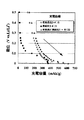
本発明に用いる黒鉛は、結晶性が高く非常に発達した積層構造を有するため、導電性が高く、かつ300mAh/g以上の高容量を示す。しかし、図1に示すように、黒鉛のみを負極活物質として用いた負極(■印)の充電容量は、低結晶性の非黒鉛カ―ボンのみを用いた負極(○印)のそれに比べて小さい。一方、非黒鉛カ―ボンと黒鉛の両者を活物質とする負極(△印)の場合、非黒鉛カ―ボンだけでなく、黒鉛にも完全に充電されるため、黒鉛が導電助剤としての役割も果たすのに加えて、負極全体の充放電容量にも大きく寄与することができる。
【0010】
また、図1に示すように、低結晶性の非黒鉛カ―ボンのみを用いた負極の充電電位は、充電末期において非常に低い(Li金属の電位に近い)ため、極板上でLi金属(デンドライト)が析出しやすいという欠点がある。しかし、図1に示すように、非黒鉛カ―ボンと黒鉛の両者を用いた負極の充電電位は、非黒鉛カ―ボン単体のそれに比べて高くなることが明らかとなつた。したがつて、非黒鉛カ―ボンと黒鉛の両方を用いることによつて、Li金属の析出が起こり難くすることもできる。さらに、図2に示すように、非黒鉛カ―ボンと黒鉛の両者を用いた負極(△印)の放電容量は、低結晶性の非黒鉛カ―ボンのみを用いた負極(○印)のそれよりわずかに小さいが、黒鉛のみを負極活物質として用いた負極(■印)と比べると、明らかに大きい。
【0011】
したがつて、非黒鉛カ―ボンと黒鉛からなる活物質とすることにより、負極全体の充放電容量を向上することができ、非黒鉛カ―ボンのみを用いた場合と比較して、リチウム金属(デンドライト)の発生を抑制できるとともに、高エネルギ―密度のリチウム二次電池が得られるものと考えられる。
【0012】
一方、電池の高容量化を達成するには、負極を高密度化、すなわち、体積あたりの容量を増大させる必要がある。ところが、非黒鉛カ―ボンはその粒子の硬さゆえに、プレスしても押し潰され難いという問題がある。そのため、非黒鉛カ―ボンを用いた負極は、カ―ボン自身が持つ空孔(ポア)以外に多くの空隙を有し、密度が低くなつてしまう。このため、電解液の負極への浸透にすぐれるものの、単位体積あたりのカ―ボンが減少するため、リチウムがド―プできる量が制限され、高容量の電池が得られないことになる。
【0013】
そこで、本発明者らが検討した結果、非黒鉛カ―ボンと黒鉛を負極活物質とする場合に、粒径が9μm以上の非黒鉛カ―ボンと、粒径が3μm以下の黒鉛を用い、かつ負極中の空隙量を15〜30体積%とすると、非黒鉛カ―ボンと黒鉛を用いた場合の上記効果を十分に発揮できることが明らかとなつた。
【0014】
すなわち、非黒鉛カ―ボンの粒径は、粒子間の空隙を一定体積以上確保して、その空隙内に黒鉛粒子を入り込ませることが必要であり、また非黒鉛カ―ボンのみを用いた場合と同等の体積で負極を作製するため、さらには粒径が小さすぎると非黒鉛カ―ボンを結着するバインダの必要量が増加してしまうため、体積あたりのカ―ボン重量が減り、容量が低下することから、非黒鉛カ―ボンの粒径としては、9μm以上であることが必要である。
【0015】
なお、非黒鉛カ―ボンの粒径があまりに大きすぎると、負極密度の減少および負荷特性の低下を招くことになるため、20μm以下であるのが好ましい。また、このような非黒鉛カ―ボンとしては、層間距離〔d002 〕が3.5Å以上で、かつc軸方向の結晶子サイズ〔Lc〕が100Å以下であるものが好ましく、層間距離〔d002 〕が3.7Å以上で、かつc軸方向の結晶子サイズ〔Lc〕が20Å以下であるものがより好ましい。これは、電池の作動電圧が高くなる領域で高容量化が可能となるためである。
【0016】
黒鉛の粒径は、上記非黒鉛カ―ボンの粒子間の空隙内に入り込ませるために、3μm以下、好ましくは3〜0.5μm、より好ましくは2〜0.5μmとするのがよく、これにより上記構造の負極とすることが可能となり、従来と同等の体積で負極を作製できる。また、このような黒鉛としては、層間距離〔d002 〕が3.4Å以下で、かつc軸方向の結晶子サイズ〔Lc〕が300Å以上であるものが好ましく、層間距離〔d002 〕が3.37Å以下で、かつc軸方向の結晶子サイズ〔Lc〕が350Å以上であるものがより好ましい。これは、電池の作動電圧が高くなる領域で高容量化が可能となるためである。
【0017】
本発明においては、上記粒径の非黒鉛カ―ボンと黒鉛を用いるとともに、負極の空隙率を15〜30体積%の範囲内に規制することが重要である。すなわち、前述のように、非黒鉛カ―ボンのみを用いた負極では、その粒子の大きさおよび硬度から、負極作製時のプレス時にプレスされにくいため、充填率が低くなる。一方、黒鉛のみを用いた負極では、粒子径が小さいため、粒子同志が近接しすぎて、電解液の浸透が十分得られないことになる。
【0018】
本発明者らの検討の結果、上記粒径の非黒鉛カ―ボンと黒鉛を用いる場合に、負極の空隙率を15〜30体積%、好ましくは20〜25体積%としたときに、電解液の浸透を良好にできるために、充放電に有効な単位体積あたりの活物質量を向上させることができることが明らかとなつた。
【0019】
すなわち、負極の空隙率を15体積%以上とすると、電解液の浸透性を十分に確保できることにより、負荷特性を向上できるとともに、活物質と電解液との接触面積を大きくすることができる。また、負極の空隙率を30体積%以下とすることにより、活物質の充填率を向上させることができ、高容量化を図ることができる。なお、本発明にいう空隙率とは、(負極体積−各固形分の真密度の逆数)/負極体積により、求めることができる
【0020】
本発明において、上記粒径の非黒鉛カ―ボンと黒鉛との混合割合は、上記の空隙率が得られるものであれば、とくにその範囲は制限されない。一般に、黒鉛粒子表面での電解液分解被膜による不可逆容量の低減を考慮して、全活物質重量に対して黒鉛が2〜30重量%の範囲となるのが望ましい。
【0021】
本発明において、負極は、たとえば、上記の非黒鉛カ―ボンと黒鉛を負極活物質とし、必要に応じて電子伝導助剤を添加し、たとえば、ポリフツ化ビニリデン、ポリテトラフルオロエチレン、エチレン−プロピレン−ジエンゴムなどのバインダを加え、さらに溶剤を加えて混合して塗料を調製し、この塗料を集電体に塗布し乾燥して、塗膜を形成することにより、作製できる。ただし、負極の作製方法は、上記の方法に限られることなく、他の方法を採用してもよい。
【0022】
本発明において、正極活物質としては、リチウム含有遷移金属酸化物が用いられ、具体的には、リチウムコバルト酸化物、リチウムニツケル酸化物、リチウムマンガン酸化物(これらは、通常、それぞれ、LiCoO2 、LiNiO2 、LiMnO2 などで表すが、これらのLiとNiの比、LiとCoの比、LiとMnの比は、化学量論組成からずれている場合が多い)などのリチウム含有複合金属化合物が単独でまたは2種以上の混合物として、あるいはそれらの固溶体として、用いられる。ただし、正極活物質は、これらにのみ限定されることはなく、他のものであつてもよい。
【0023】
正極の作製に際しては、上記の正極活物質に、必要により、りん状黒鉛、アセチレンブラツク、カ―ボンブラツクなどの電子伝導助剤や、ポリフツ化ビニリデン、ポリテトラフルオロエチレン、エチレン−プロピレン−ジエンゴム(EPDM)などのバインダを添加してもよい。正極は、これらの成分を溶剤に溶解または分散させて調製した塗料を集電体に塗布し乾燥して、集電体上に正極活物質を含有する塗膜を形成することにより、作製される。ただし、正極の作製方法は、上記の方法に限られることなく、他の方法を採用してもよい。
【0024】
本発明において、正極と負極における活物質の量比としては、正極活物質の種類よつても異なるが、たとえば、正極活物質としてリチウムコバルト酸化物(LiCoO2 )を用いる場合、正極活物質/負極活物質(非黒鉛カ―ボンと黒鉛)=1.8〜2.8(重量比)であるのが好ましい。
【0025】
本発明において、正極および負極用の塗料を集電体に塗布する方法としては、たとえば、押し出しコ―タ、リバ―スロ―ラ、ドクタ―ブレ―ドなどをはじめ、各種の塗布方法を採用することができる。また、上記の集電体としては、アルミニウム、ステンレス鋼、チタン、銅などの金属の網、パンチドメタル、エキスパンドメタル、フオ―ムメタル、箔などが用いられる。
【0026】
本発明において、有機電解液の溶媒としては、とくに限定されないが、鎖状エステルを主溶媒として用いるのが好ましい。このような鎖状エステルとしては、たとえば、ジメチルカ―ボネ―ト(DMC)、ジエチルカ―ボネ―ト(DEC)、メチルエチルカ―ボネ―ト(MEC)、エチルアセテ―ト(EA)、プロピオン酸メチル(PM)などの鎖状のCOO−結合を有する有機溶媒が挙げられる。この鎖状エステルが電解液の主溶媒であるとは、この鎖状エステルが全電解液溶媒中の50体積%より多い体積を占めることを意味しており、とくに65体積%以上、さらに70体積%以上を占めているのが好ましく、最も好ましくは75体積%以上を占めているのがよい。
【0027】
上記の鎖状エステルを主溶媒にするのが好ましい理由は、鎖状エステルが全電解液溶媒中の50体積%を超えると、電池特性、とくに低温特性が改善されるためである。ただし、電解液溶媒は、上記の鎖状エステルのみで構成するよりも、電池容量の向上を図るため、上記の鎖状エスルに誘電率の高いエステル(誘電率30以上のエステル)を混合して用いのが好ましい。
【0028】
この誘電率の高いエステルの全電解液溶媒中に占める量は、10体積%以上、とくに20体積%以上が好ましい。10体積%以上になると、容量の向上が明確に発現され、20体積%以上になると容量の向上がより一層明確に発現される。ただし、誘電率の高いエステルが多くなりすぎると、電池の放電特性が低下する傾向があり、誘電率の高いエステルの全電解液溶媒中で占める量は、その上限として、40体積%以下であるのが好ましく、より好ましくは30体積%以下、さらに好ましくは25体積%以下であるのがよい。
【0029】
上記の誘電率の高いエステルとしては、たとえば、エチレンカ―ボネ―ト(EC)、プロピレンカ―ボネ―ト(PC)、ブチレンカ―ボネ―ト(BC)、ガンマ―ブチロラクトン(γ−BL)、エチレングリコ―ルサルフアイト(EGS)などが挙げられ、とくにエチレンカ―ボネ―ト、プロピレンカ―ボネ―トなどの環状構造のものが好ましく、とりわけ環状のカ―ボネ―トが好ましい。具体的には、エチレンカ―ボネ―トが最も好ましい。
【0030】
上記の誘電率の高いエステル以外に、たとえば、1,2−ジメトキシエタン(DME)、1,3−ジオキソラン(DO)、テトラヒドロフラン(THF)、2−メチル−テトラヒドロフラン(2−Me−THF)、ジエチルエ―テル(DEE)などを併用してもよい。そのほか、アミンイミド系有機溶媒や、含硫黄または含フツ素系有機溶媒なども用いることができる。
【0031】
有機電解液の電解質としては、たとえば、LiClO4 、LiPF6 、LiBF4 、LiAsF6 、LiSbF6 、LiCF3 SO3 、LiC4 F9 SO3 、LiCF3 CO2 、Li2 C2 F4 (SO3 )2 、LiN(CF3 SO2 )2 、LiC(CF3 SO2 )3 、LiCn F2n+1SO3 (n≧2)などが単独でまたは2種以上混合して用いられる。これらの中でも、LiPF6 やLiC4 F9 SO3 などは充放電特性が良好なため、とくに好ましい。有機電解液中における電解質の濃度は、とくに限定されないが、通常は0.3〜1.7モル/リツトル、好ましくは0.4〜1.5モル/リツトルであるのがよい。
【0032】
本発明のリチウム二次電池は、電池缶内に、上記したようなリチウム含有遷移金属カルコゲナイドを活物質とした正極、上記した特定粒径の非黒鉛カ―ボンと黒鉛を活物質とした負極、ならびに上記した有機電解液を内填した構成をとるものであつて、上記の正極と負極との間には適宜のセパレ―タが介装される。このセパレ―タとしては、強度が十分でしかも電解液を多く保持できるものがよく、この点から、厚さが10〜50μmで、開口率が30〜70%であるポリプロピレン製またはポリエチレン製のセパレ―タが好ましい。
【0033】
【実施例】
つぎに、本発明の実施例を記載して、より具体的に説明する。
【0034】
実施例1
非黒鉛カ―ボンとして、フエノ―ル樹脂を1,100℃で焼成したバルクカ―ボンを粉砕して得た粒径10μmの粉末(d002 :3.8Å、Lc:12Å)を用い、黒鉛として、石油ピツチを3,000℃で焼成したバルクカ―ボンを粉砕して得た粒径1μmの粉末(d002 :3.37Å、Lc:360Å)を用いた。この非黒鉛カ―ボンと黒鉛を重量比90:10で混合して負極活物質とし、バインダとしてポリフツ化ビニリデン(PVDF)、溶媒としてN−メチル−2−ピロリドンを用いて、負極合剤を調製し、銅箔の両面に塗布した。これを乾燥したのち、40Kg/cm2 でカレンダ―ロ―ルプレスして、シ―ト負極とした。このようにして得たシ―ト負極の空隙率は23体積%であつた。
【0035】
つぎに、このシ―ト負極を作用極とし、対極および参照極にリチウム箔を用いて、エチレンカ―ボネ―トとメチルエチルカ―ボネ―トの重量比1:1の混合溶媒にLiPF6 を1モル/リツトルの濃度に溶解した溶液を有機電解液として、モデルセルを作製した。
【0036】
実施例2
負極活物質において、非黒鉛カ―ボンとして、フエノ―ル樹脂を1,100℃で焼成したバルクカ―ボンを粉砕して得た粒径20μmの粉末(d002 :3.8Å、Lc:12Å)を用い、シ―ト負極の空隙率を21体積%とした以外は、実施例1と同様にして、モデルセルを作製した。
【0037】
実施例3
負極活物質において、黒鉛として、石油ピツチを3,000℃で焼成したバルクカ―ボンを粉砕して得た粒径3μmの粉末(d002 :3.37Å、Lc:360Å)を用い、シ―ト負極の空隙率を24体積%とした以外は、実施例1と同様にして、モデルセルを作製した。
【0038】
実施例4
負極活物質において、非黒鉛カ―ボンとして、石油ピツチを800℃で焼成したバルクカ―ボンを粉砕して得た粒径10μmの粉末(d002 :3.54Å、Lc:17Å)を用い、シ―ト負極の空隙率を26体積%とした以外は、実施例1と同様にして、モデルセルを作製した。
【0039】
実施例5
非黒鉛カ―ボンと黒鉛を重量比70:30で混合したものを負極活物質とし、シ―ト負極の空隙率を22体積%とした以外は、実施例1と同様にして、モデルセルを作製した。
【0040】
比較例1
負極活物質において、黒鉛を使用せず、そのぶん非黒鉛カ―ボンの使用量を増やし、シ―ト負極の空隙率を35体積%とした以外は、実施例1と同様にして、モデルセルを作製した。
【0041】
比較例2
負極活物質において、非黒鉛カ―ボンを使用せず、そのぶん黒鉛の使用量を増やし、シ―ト負極の空隙率を10体積%とした以外は、実施例1と同様にして、モデルセルを作製した。
【0042】
比較例3
負極活物質において、粒径10μmの非黒鉛カ―ボンに代えて、粒径4μmの非黒鉛カ―ボンを用い、シ―ト負極の空隙率を27体積%とした以外は、実施例1と同様にして、モデルセルを作製した。
【0043】
比較例4
負極活物質において、粒径1μmの黒鉛に代えて、粒径10μmの黒鉛を用い、シ―ト負極の空隙率を33体積%とした以外は、実施例1と同様にして、モデルセルを作製した。
【0044】
比較例5
カレンダ―ロ―ルプレス圧を15Kg/cm2 とし、シ―ト負極の空隙率を34体積%とした以外は、実施例1と同様にして、モデルセルを作製した。
【0045】
比較例6
カレンダ―ロ―ルプレス圧を90Kg/cm2 とし、シ―ト負極の空隙率を13体積%とした以外は、実施例1と同様にして、モデルセルを作製した。
【0046】
上記の実施例1〜5および比較例1〜6の各モデルセルについて、0V対Li/Li+ まで充電したのち、0.5mA/cm2 の電流密度で1.5Vまで放電させたときの電極体積あたりの放電容量、5mA/cm2 での0.5mA/cm2 の場合に対する放電容量維持率(負荷特性)、ならびに初回充放電における不可逆容量(リテンシヨン)の放電容量に対する割合を示した。これらの結果は、下記の表1に示されるとおりであつた。
【0047】

上記の表1から明らかなように、負極活物質として非黒鉛カ―ボンと黒鉛を使用した実施例1〜5では、黒鉛を添加していない比較例1に比べて、体積あたりの放電容量(mAh/cc)が増加し、さらに黒鉛の効果が加わつて負荷特性が著しく向上していることがわかる。
【0049】
これに対し、黒鉛のみからなる比較例2では、容量は同程度であるが、粒子間の空隙が少なくなるため、負荷特性およびリテンシヨンが低下している。また、粒径が4μmの非黒鉛カ―ボンを用いた比較例3では、それを結着するバインダ量が他に比べて多くなるため、負極合剤に対する活物質密度(カ―ボン密度)が低くなり、体積あたりの放電容量が小さくなり、負荷特性も低下している。さらに、粒径が10μmの黒鉛を用いた比較例4では、負極の空隙率ほほとんど増加せず、放電容量は低いものとなつている。また、非黒鉛カ―ボンと黒鉛を活物質とした負極であつても、プレス圧の設定により空隙率を大きくしすぎた比較例5では、体積あたりの容量が低下し、逆に空隙率を小さくしすぎた比較例6では、電極の吸液性が低下するため、負荷特性が悪くなつている。
【0050】
【発明の効果】
以上のように、本発明は、粒径9μm以上の非黒鉛カ―ボンと粒径3μm以下の黒鉛を負極活物質として使用し、かつ負極の空隙率を15〜30体積%に設定したことにより、非黒鉛カ―ボン、黒鉛のみからなる負極活物質では困難であつた負極の高密度化が容易となり、高容量で負荷特性およびリテンシヨンにすぐれるリチウム二次電池を提供することができる。
【図面の簡単な説明】
【図1】Liに対する充電電位と充電容量との関係を示す特性図である。
【図2】Liに対する放電電位と放電容量との関係を示す特性図である。[0001]
BACKGROUND OF THE INVENTION
The present invention relates to a lithium secondary battery, and more particularly to improvement of a negative electrode active material of a lithium secondary battery.
[0002]
[Prior art]
Carbon is generally used as the negative electrode active material for lithium secondary batteries. This carbon has a layered structure, and its crystallinity is determined by the temperature at which the raw material is fired. It is known that the higher the carbon crystallinity, the higher the capacity. The existing interfacial distance [d 002 ] of natural graphite having the highest crystallinity is 3.55 mm, the crystallite size [Lc] in the c-axis direction is 1,000 mm or more, and the theoretical capacity is 372 mAh / g (ie, C 6 Li).
[0003]
However, due to recent active research and development, many non-graphite carbons with a capacity far exceeding the theoretical capacity of graphite have appeared. For example, a polyacene organic polymer semiconductor obtained by baking a phenol resin at about 700 ° C. has a high capacity of 850 mAh / g per carbon weight (Abstracts of the 35th Battery Discussion Meeting, 2B15). Carbons obtained by baking organic polymer compounds such as paraffinylene at 500 to 1,500 ° C. have a high capacity of 680 mAh / g (Nikkei Sangyo Shimbun, May 2, 1994), respectively. It has been reported that The reason for this is that the interlayer distance [d 002 ] of non-graphite carbon is much larger than that of natural graphite, and there are many vacancies in addition to the layer structure, and a large amount of lithium is doped there. Therefore, it is considered that high capacity can be obtained.
[0004]
[Problems to be solved by the invention]
However, in general, non-graphite carbon having many pores has a lower true specific gravity than graphite. That is, the true specific gravity of graphite is 2.0 g / cc or more, whereas that of non-graphite carbon is about 1.5 to 1.7 g / cc. In addition, since non-graphite carbon has a small laminated structure, deformation due to slippage between layer surfaces hardly occurs, and the hardness of the particles is larger than that of graphite. Therefore, when non-graphite carbon and a binder are mixed and pressed to produce an electrode, it is harder to fill than when graphite is used, and therefore non-graphite carbon has a high capacity per weight. As shown, the capacity per electrode volume is lower than that of graphite.
[0005]
In addition, since non-graphite carbon having an amorphous structure exhibits electrical isotropy, the conductivity of the particles is lower than that of graphite, and there are many non-graphite carbons in the voids present in non-graphite carbon. The diffusion rate of lithium has the disadvantage that it is very slow compared to that between layers. For this reason, when the non-graphite carbon is used as the negative electrode active material of the lithium secondary battery, the load characteristics of the battery are deteriorated as compared with the case of using graphite, and the battery capacity is also lowered.
[0006]
Therefore, an object of the present invention is to provide a lithium secondary battery that improves the negative electrode of the lithium secondary battery and has a high capacity and excellent load characteristics.
[0007]
[Means for Solving the Problems]
As a result of diligent investigations for the above object, the present inventors have used non-graphite carbon having a specific particle size and graphite as a negative electrode active material, and setting the porosity of the negative electrode within a specific range. Thus, it was found that a lithium secondary battery having a high capacity and excellent load characteristics can be obtained, and the present invention has been completed.
[0008]
That is, the present invention relates to a positive electrode, a negative electrode, and a lithium secondary battery containing an organic electrolyte containing a lithium-containing transition metal chalcogenide as an active material, a non-graphite carbon having a particle size of 9 μm or more and a particle size as a negative electrode active material. The present invention relates to a lithium secondary battery (Claim 1) characterized in that graphite of 3 μm or less is used and the porosity of the negative electrode is 15 to 30% by volume. The non-graphite carbon has a configuration in which the interlayer distance [d 002 ] is 3.5 mm or more and the crystallite size [Lc] in the c-axis direction is 100 mm or less (Claim 2), and the graphite has an interlayer distance. A configuration in which [d 002 ] is 3.4 mm or less and a crystallite size [Lc] in the c-axis direction is 300 mm or more (Claim 3) is a preferable embodiment.
[0009]
DETAILED DESCRIPTION OF THE INVENTION
Since the graphite used in the present invention has a highly crystallized laminated structure, it has high conductivity and a high capacity of 300 mAh / g or more. However, as shown in FIG. 1, the charge capacity of the negative electrode (marked with ■ only) using only graphite as the negative electrode active material is higher than that of the negative electrode using only low crystalline non-graphite carbon (marked with circle). small. On the other hand, in the case of a negative electrode (Δ mark) using both non-graphite carbon and graphite as active materials, not only non-graphite carbon but also graphite is completely charged, so graphite is used as a conductive aid. In addition to playing a role, it can greatly contribute to the charge / discharge capacity of the entire negative electrode.
[0010]
In addition, as shown in FIG. 1, the charging potential of the negative electrode using only the low crystalline non-graphite carbon is very low at the end of charging (close to the potential of Li metal). There is a drawback that (dendrite) is likely to precipitate. However, as shown in FIG. 1, it has been clarified that the charging potential of the negative electrode using both non-graphite carbon and graphite is higher than that of the non-graphite carbon alone. Therefore, by using both non-graphite carbon and graphite, it is possible to make it difficult for Li metal to precipitate. Furthermore, as shown in FIG. 2, the discharge capacity of the negative electrode (Δ mark) using both non-graphite carbon and graphite is that of the negative electrode (○ mark) using only low crystalline non-graphite carbon. Although slightly smaller than that, it is clearly larger than the negative electrode (■ mark) using only graphite as the negative electrode active material.
[0011]
Therefore, by using an active material composed of non-graphite carbon and graphite, the charge / discharge capacity of the entire negative electrode can be improved. Compared with the case of using only non-graphite carbon, lithium metal It is considered that the generation of (dendrites) can be suppressed and a high energy density lithium secondary battery can be obtained.
[0012]
On the other hand, in order to achieve higher capacity of the battery, it is necessary to increase the density of the negative electrode, that is, increase the capacity per volume. However, non-graphite carbon has a problem that it is difficult to be crushed even if pressed because of the hardness of the particles. Therefore, the negative electrode using non-graphite carbon has many voids other than the pores that the carbon itself has, and the density becomes low. For this reason, although the electrolyte permeates into the negative electrode, carbon per unit volume is reduced, so that the amount of lithium that can be doped is limited, and a high-capacity battery cannot be obtained.
[0013]
Therefore, as a result of investigations by the present inventors, when non-graphite carbon and graphite are used as the negative electrode active material, non-graphite carbon having a particle size of 9 μm or more and graphite having a particle size of 3 μm or less are used. Further, it has been clarified that when the void amount in the negative electrode is 15 to 30% by volume, the above-described effect can be sufficiently exhibited when non-graphite carbon and graphite are used.
[0014]
In other words, the particle size of non-graphite carbon needs to ensure a certain volume or more of voids between the particles and allow graphite particles to enter the voids, or when only non-graphite carbon is used. In order to produce a negative electrode with the same volume as that, and if the particle size is too small, the amount of binder that binds non-graphite carbon increases, so the weight of carbon per volume decreases and the capacity Therefore, the particle size of the non-graphite carbon needs to be 9 μm or more.
[0015]
Note that if the particle size of the non-graphite carbon is too large, the negative electrode density and load characteristics are deteriorated, and therefore it is preferably 20 μm or less. As such non-graphite carbon, those having an interlayer distance [d 002 ] of 3.5 mm or more and a crystallite size [Lc] in the c-axis direction of 100 mm or less are preferable, and the interlayer distance [d 002 ] is 3.7 mm or more, and the crystallite size [Lc] in the c-axis direction is more preferably 20 mm or less. This is because the capacity can be increased in a region where the operating voltage of the battery is high.
[0016]
The particle size of the graphite should be 3 μm or less, preferably 3 to 0.5 μm, more preferably 2 to 0.5 μm in order to enter the voids between the non-graphite carbon particles. Thus, the negative electrode having the above structure can be obtained, and the negative electrode can be produced with the same volume as the conventional one. Such graphite preferably has an interlayer distance [d 002 ] of 3.4 mm or less and a c-axis direction crystallite size [Lc] of 300 mm or more, and an interlayer distance [d 002 ] of 3 It is more preferable that the crystallite size [Lc] in the c-axis direction is 350 mm or less and 37 mm or less. This is because the capacity can be increased in a region where the operating voltage of the battery is high.
[0017]
In the present invention, it is important to use non-graphite carbon and graphite having the above particle sizes and to regulate the porosity of the negative electrode within the range of 15 to 30% by volume. That is, as described above, a negative electrode using only non-graphite carbon has a low filling rate because it is difficult to be pressed at the time of negative electrode production due to the size and hardness of the particles. On the other hand, in the negative electrode using only graphite, since the particle diameter is small, the particles are too close to each other, so that sufficient penetration of the electrolytic solution cannot be obtained.
[0018]
As a result of the study by the present inventors, when non-graphite carbon and graphite having the above particle sizes are used, the electrolyte solution has a negative electrode porosity of 15 to 30% by volume, preferably 20 to 25% by volume. It has been clarified that the amount of active material per unit volume effective for charging and discharging can be improved.
[0019]
That is, when the porosity of the negative electrode is 15% by volume or more, the permeability of the electrolytic solution can be sufficiently secured, so that the load characteristics can be improved and the contact area between the active material and the electrolytic solution can be increased. In addition, by setting the porosity of the negative electrode to 30% by volume or less, the filling rate of the active material can be improved and the capacity can be increased. The porosity referred to in the present invention can be determined by (negative electrode volume−reciprocal of true density of each solid content) / negative electrode volume.
In the present invention, the mixing ratio of the non-graphite carbon having the above particle size and graphite is not particularly limited as long as the above porosity can be obtained. In general, considering the reduction of irreversible capacity due to the electrolytic solution decomposition coating on the surface of the graphite particles, it is desirable that the graphite is in the range of 2 to 30% by weight with respect to the total active material weight.
[0021]
In the present invention, the negative electrode includes, for example, the above non-graphite carbon and graphite as a negative electrode active material, and an electron conduction aid is added as necessary. For example, polyvinylidene fluoride, polytetrafluoroethylene, ethylene-propylene -A binder such as diene rubber is added, a solvent is further added and mixed to prepare a paint, and this paint is applied to a current collector and dried to form a coating film. However, the method for manufacturing the negative electrode is not limited to the above method, and other methods may be adopted.
[0022]
In the present invention, a lithium-containing transition metal oxide is used as the positive electrode active material. Specifically, lithium cobalt oxide, lithium nickel oxide, lithium manganese oxide (these are usually LiCoO 2 , LiNiO 2 , LiMnO 2 , etc. The lithium-containing composite metal compound such as Li / Ni ratio, Li / Co ratio, and Li / Mn ratio often deviates from the stoichiometric composition. Are used alone or as a mixture of two or more thereof, or as a solid solution thereof. However, the positive electrode active material is not limited to these, and other materials may be used.
[0023]
In the production of the positive electrode, if necessary, the above positive electrode active material may include an electron conduction aid such as phosphorous graphite, acetylene black, and carbon black, polyvinylidene fluoride, polytetrafluoroethylene, ethylene-propylene-diene rubber (EPDM). A binder such as) may be added. The positive electrode is produced by applying a paint prepared by dissolving or dispersing these components in a solvent to a current collector and drying to form a coating film containing the positive electrode active material on the current collector. . However, the method for manufacturing the positive electrode is not limited to the above method, and other methods may be adopted.
[0024]
In the present invention, the amount ratio of the active material in the positive electrode and the negative electrode differs depending on the type of the positive electrode active material. For example, when lithium cobalt oxide (LiCoO 2 ) is used as the positive electrode active material, the positive electrode active material / negative electrode The active material (non-graphite carbon and graphite) is preferably 1.8 to 2.8 (weight ratio).
[0025]
In the present invention, various coating methods such as an extrusion coater, a reverse roller, a doctor blade, etc. are adopted as a method for applying the positive electrode and negative electrode paints to the current collector. be able to. As the current collector, a metal net such as aluminum, stainless steel, titanium, or copper, a punched metal, an expanded metal, a form metal, or a foil is used.
[0026]
In the present invention, the solvent of the organic electrolyte solution is not particularly limited, but a chain ester is preferably used as the main solvent. Examples of such chain esters include dimethyl carbonate (DMC), diethyl carbonate (DEC), methyl ethyl carbonate (MEC), ethyl acetate (EA), and methyl propionate (PM). And organic solvents having a chain-like COO-bond such as That this chain ester is the main solvent of the electrolytic solution means that this chain ester occupies a volume of more than 50% by volume in the total electrolyte solvent, particularly 65% by volume or more, and further 70% by volume. % Or more is preferred, and most preferably 75% or more.
[0027]
The reason why it is preferable to use the chain ester as the main solvent is that when the chain ester exceeds 50% by volume in the total electrolyte solution, battery characteristics, particularly low temperature characteristics, are improved. However, in order to improve battery capacity, the electrolytic solution solvent is made by mixing an ester having a high dielectric constant (an ester having a dielectric constant of 30 or more) with the above-mentioned chain ester in order to improve battery capacity. Preferably used.
[0028]
The amount of the ester having a high dielectric constant in the total electrolyte solvent is preferably 10% by volume or more, particularly preferably 20% by volume or more. When it is 10% by volume or more, the improvement in capacity is clearly expressed, and when it is 20% by volume or more, the improvement in capacity is more clearly expressed. However, when the amount of the ester having a high dielectric constant is excessive, the discharge characteristics of the battery tend to be lowered. The amount of the ester having a high dielectric constant in the total electrolyte solvent is 40% by volume or less as the upper limit. More preferably, it is 30 volume% or less, More preferably, it is good that it is 25 volume% or less.
[0029]
Examples of the esters having a high dielectric constant include ethylene carbonate (EC), propylene carbonate (PC), butylene carbonate (BC), gamma-butyrolactone (γ-BL), and ethylene. Examples thereof include glycolsulfite (EGS). Particularly preferred are cyclic structures such as ethylene carbonate and propylene carbonate, and particularly preferred is cyclic carbonate. Specifically, ethylene carbonate is most preferable.
[0030]
In addition to the ester having a high dielectric constant, for example, 1,2-dimethoxyethane (DME), 1,3-dioxolane (DO), tetrahydrofuran (THF), 2-methyl-tetrahydrofuran (2-Me-THF), diethyl ether -Tel (DEE) may be used in combination. In addition, amine imide organic solvents, sulfur-containing or fluorine-containing organic solvents, and the like can also be used.
[0031]
As the electrolyte in the organic electrolytic solution, for example, LiClO 4, LiPF 6, LiBF 4, LiAsF 6, LiSbF 6, LiCF 3 SO 3, LiC 4 F 9 SO 3, LiCF 3 CO 2, Li 2 C 2 F 4 (SO 3 ) 2 , LiN (CF 3 SO 2 ) 2 , LiC (CF 3 SO 2 ) 3 , LiC n F 2n + 1 SO 3 (n ≧ 2) or the like may be used alone or in combination. Among these, LiPF 6 and LiC 4 F 9 SO 3 are particularly preferable because of good charge / discharge characteristics. The concentration of the electrolyte in the organic electrolytic solution is not particularly limited, but is usually 0.3 to 1.7 mol / liter, preferably 0.4 to 1.5 mol / liter.
[0032]
The lithium secondary battery of the present invention includes, in a battery can, a positive electrode using the above lithium-containing transition metal chalcogenide as an active material, a negative electrode using a non-graphite carbon having a specific particle size and graphite as an active material, In addition, the above-described organic electrolyte solution is included, and an appropriate separator is interposed between the positive electrode and the negative electrode. As this separator, a separator having sufficient strength and capable of holding a large amount of electrolyte is preferable. From this point, a separator made of polypropylene or polyethylene having a thickness of 10 to 50 μm and an aperture ratio of 30 to 70% is preferable. -Is preferred.
[0033]
【Example】
Next, examples of the present invention will be described in more detail.
[0034]
Example 1
As a non-graphite carbon, a powder having a particle diameter of 10 μm (d 002 : 3.8 mm, Lc: 12 mm) obtained by pulverizing bulk carbon obtained by firing phenol resin at 1,100 ° C. was used as graphite. A powder (d 002 : 3.37 Å, Lc: 360 Å) having a particle size of 1 μm obtained by pulverizing bulk carbon obtained by firing petroleum pitch at 3,000 ° C. was used. A non-graphite carbon and graphite are mixed at a weight ratio of 90:10 to form a negative electrode active material, and a negative electrode mixture is prepared using polyvinylidene fluoride (PVDF) as a binder and N-methyl-2-pyrrolidone as a solvent. And applied to both sides of the copper foil. After drying this, it was calender-roll pressed at 40 kg / cm 2 to obtain a sheet negative electrode. The sheet negative electrode thus obtained had a porosity of 23% by volume.
[0035]
Next, using this sheet negative electrode as a working electrode, and using lithium foil as a counter electrode and a reference electrode, 1 mol of LiPF 6 was added to a mixed solvent of ethylene carbonate and methyl ethyl carbonate in a weight ratio of 1: 1. A model cell was prepared using an organic electrolyte as a solution dissolved at a concentration of / liter.
[0036]
Example 2
In the negative electrode active material, powder having a particle size of 20 μm obtained by pulverizing bulk carbon obtained by firing phenol resin at 1,100 ° C. as non-graphite carbon (d 002 : 3.8 mm, Lc: 12 mm) A model cell was prepared in the same manner as in Example 1 except that the porosity of the sheet negative electrode was changed to 21% by volume.
[0037]
Example 3
In the negative electrode active material, a powder having a particle diameter of 3 μm (d 002 : 3.37 mm, Lc: 360 mm) obtained by pulverizing bulk carbon obtained by firing petroleum pitch at 3,000 ° C. is used as the graphite. A model cell was produced in the same manner as in Example 1 except that the porosity of the negative electrode was 24% by volume.
[0038]
Example 4
In the negative electrode active material, a powder (d 002 : 3.54 mm, Lc: 17 mm) having a particle diameter of 10 μm obtained by pulverizing bulk carbon obtained by firing petroleum pitch at 800 ° C. is used as non-graphite carbon. A model cell was produced in the same manner as in Example 1 except that the porosity of the negative electrode was 26% by volume.
[0039]
Example 5
A model cell was prepared in the same manner as in Example 1 except that a mixture of non-graphite carbon and graphite at a weight ratio of 70:30 was used as the negative electrode active material, and the porosity of the sheet negative electrode was 22% by volume. Produced.
[0040]
Comparative Example 1
In the negative electrode active material, a model cell was used in the same manner as in Example 1 except that graphite was not used, and that the amount of non-graphite carbon was increased, and the porosity of the sheet negative electrode was 35% by volume. Was made.
[0041]
Comparative Example 2
In the negative electrode active material, a model cell was used in the same manner as in Example 1 except that non-graphite carbon was not used, the amount of graphite used was increased, and the porosity of the sheet negative electrode was changed to 10% by volume. Was made.
[0042]
Comparative Example 3
Example 1 except that in the negative electrode active material, non-graphite carbon having a particle size of 4 μm was used instead of non-graphite carbon having a particle size of 10 μm, and the porosity of the sheet negative electrode was set to 27% by volume. Similarly, a model cell was produced.
[0043]
Comparative Example 4
A model cell was prepared in the same manner as in Example 1 except that graphite having a particle diameter of 10 μm was used instead of graphite having a particle diameter of 1 μm in the negative electrode active material, and the porosity of the sheet negative electrode was changed to 33% by volume. did.
[0044]
Comparative Example 5
A model cell was produced in the same manner as in Example 1 except that the calender roll press pressure was 15 kg / cm 2 and the porosity of the sheet negative electrode was 34% by volume.
[0045]
Comparative Example 6
A model cell was produced in the same manner as in Example 1 except that the calendar roll press pressure was 90 kg / cm 2 and the porosity of the sheet negative electrode was 13% by volume.
[0046]
About each model cell of said Examples 1-5 and Comparative Examples 1-6, after charging to 0V vs. Li / Li +, it was discharged to 1.5V at a current density of 0.5 mA / cm < 2 > discharge capacity per volume, the discharge capacity retention ratio for the case of 0.5 mA / cm 2 at 5 mA / cm 2 (load characteristics), and showed the ratio of the discharge capacity of the irreversible capacity (Ritenshiyon) in initial charge and discharge. These results were as shown in Table 1 below.
[0047]
As apparent from Table 1 above, in Examples 1 to 5 using non-graphite carbon and graphite as the negative electrode active material, compared to Comparative Example 1 in which no graphite was added, the discharge capacity per volume ( mAh / cc) is increased, and it can be seen that the load characteristics are remarkably improved by adding the effect of graphite.
[0049]
On the other hand, in Comparative Example 2 made of only graphite, the capacity is almost the same, but since the voids between the particles are reduced, the load characteristics and the retention are lowered. Further, in Comparative Example 3 using a non-graphite carbon having a particle size of 4 μm, the amount of the binder that binds it is larger than the others, so that the active material density (carbon density) relative to the negative electrode mixture is high. The discharge capacity per volume is reduced, and the load characteristics are also reduced. Furthermore, in Comparative Example 4 using graphite having a particle size of 10 μm, the porosity of the negative electrode is hardly increased and the discharge capacity is low. Further, even in the negative electrode using non-graphite carbon and graphite as the active material, in Comparative Example 5 in which the porosity was increased too much by setting the press pressure, the capacity per volume decreased, and conversely, the porosity was decreased. In Comparative Example 6, which is too small, the liquid absorption of the electrode is lowered, and the load characteristics are getting worse.
[0050]
【The invention's effect】
As described above, the present invention uses non-graphite carbon having a particle size of 9 μm or more and graphite having a particle size of 3 μm or less as the negative electrode active material, and the negative electrode porosity is set to 15 to 30% by volume. Further, it is easy to increase the density of the negative electrode, which is difficult with a negative electrode active material composed of non-graphite carbon and graphite, and a lithium secondary battery having high capacity and excellent load characteristics and retention can be provided.
[Brief description of the drawings]
FIG. 1 is a characteristic diagram showing a relationship between a charging potential and a charging capacity with respect to Li.
FIG. 2 is a characteristic diagram showing the relationship between the discharge potential and discharge capacity for Li.
Claims (4)
Priority Applications (1)
| Application Number | Priority Date | Filing Date | Title |
|---|---|---|---|
| JP09327297A JP3613372B2 (en) | 1997-04-11 | 1997-04-11 | Lithium secondary battery |
Applications Claiming Priority (1)
| Application Number | Priority Date | Filing Date | Title |
|---|---|---|---|
| JP09327297A JP3613372B2 (en) | 1997-04-11 | 1997-04-11 | Lithium secondary battery |
Publications (2)
| Publication Number | Publication Date |
|---|---|
| JPH10284060A JPH10284060A (en) | 1998-10-23 |
| JP3613372B2 true JP3613372B2 (en) | 2005-01-26 |
Family
ID=14077824
Family Applications (1)
| Application Number | Title | Priority Date | Filing Date |
|---|---|---|---|
| JP09327297A Expired - Fee Related JP3613372B2 (en) | 1997-04-11 | 1997-04-11 | Lithium secondary battery |
Country Status (1)
| Country | Link |
|---|---|
| JP (1) | JP3613372B2 (en) |
Cited By (1)
| Publication number | Priority date | Publication date | Assignee | Title |
|---|---|---|---|---|
| EP2660903B1 (en) * | 2012-04-30 | 2020-05-13 | Samsung SDI Co., Ltd. | Negative electrode composition for rechargeable lithium battery, negative electrode comprising same and rechargeable lithium battery comprising same |
Families Citing this family (7)
| Publication number | Priority date | Publication date | Assignee | Title |
|---|---|---|---|---|
| JP2001160391A (en) * | 1999-12-06 | 2001-06-12 | Sanyo Electronic Components Co Ltd | Nonaqueous electrolyte secondary battery |
| JP5802513B2 (en) * | 2011-10-14 | 2015-10-28 | 株式会社日立製作所 | Secondary battery negative electrode, non-aqueous electrolyte secondary battery using secondary battery negative electrode |
| JP2013222550A (en) * | 2012-04-13 | 2013-10-28 | Sumitomo Bakelite Co Ltd | Negative electrode material, negative electrode and lithium ion secondary battery |
| JP2013222551A (en) * | 2012-04-13 | 2013-10-28 | Sumitomo Bakelite Co Ltd | Negative electrode material, negative electrode, and lithium ion secondary battery |
| CN104838526B (en) * | 2012-12-13 | 2017-08-18 | 昭和电工株式会社 | Anode material for lithium-ion secondary battery, lithium ion secondary battery cathode piece and lithium secondary battery |
| WO2015029766A1 (en) * | 2013-08-28 | 2015-03-05 | Jsr株式会社 | Electrode material, electrode, and capacitor device |
| CN112673503A (en) | 2018-07-19 | 2021-04-16 | 株式会社杰士汤浅国际 | Nonaqueous electrolyte electricity storage element and electricity storage device |
-
1997
- 1997-04-11 JP JP09327297A patent/JP3613372B2/en not_active Expired - Fee Related
Cited By (1)
| Publication number | Priority date | Publication date | Assignee | Title |
|---|---|---|---|---|
| EP2660903B1 (en) * | 2012-04-30 | 2020-05-13 | Samsung SDI Co., Ltd. | Negative electrode composition for rechargeable lithium battery, negative electrode comprising same and rechargeable lithium battery comprising same |
Also Published As
| Publication number | Publication date |
|---|---|
| JPH10284060A (en) | 1998-10-23 |
Similar Documents
| Publication | Publication Date | Title |
|---|---|---|
| US10361432B2 (en) | Non-aqueous secondary battery | |
| JP4868556B2 (en) | Lithium secondary battery | |
| JP4837614B2 (en) | Lithium secondary battery | |
| JP5220273B2 (en) | Electrode and non-aqueous secondary battery using the same | |
| JP6253411B2 (en) | Lithium secondary battery | |
| JP4985524B2 (en) | Lithium secondary battery | |
| US20080286657A1 (en) | Non-aqueous electrolyte secondary battery | |
| JP6995738B2 (en) | Positive electrode for lithium-ion secondary battery and lithium-ion secondary battery | |
| JP2012003997A (en) | Nonaqueous electrolyte secondary cell | |
| US20080286654A1 (en) | Non-aqueous electrolyte secondary battery | |
| JP2002025611A (en) | Nonaqueous electrolyte secondary battery | |
| US20110236758A1 (en) | Non-aqueous electrolyte secondary battery and fabrication method for non-aqueous electrolyte secondary battery | |
| US20120082896A1 (en) | Nonaqueous electrolyte secondary battery | |
| JP3613372B2 (en) | Lithium secondary battery | |
| US20230135194A1 (en) | Negative electrode and secondary battery comprising the same | |
| JP2004234977A (en) | Positive electrode material for lithium secondary battery, manufacturing method of same, and lithium secondary battery using same | |
| JPH09161778A (en) | Organic electrolyte secondary battery | |
| KR101084080B1 (en) | Non-aqueous electrolyte secondary cell | |
| JP5978024B2 (en) | Non-aqueous secondary battery | |
| JP2000195518A (en) | Nonaqueous electrolyte secondary battery | |
| JP4400014B2 (en) | Negative electrode active material for battery and nonaqueous electrolyte battery using the same | |
| JP4158212B2 (en) | Method for producing lithium secondary battery and method for producing positive electrode active material for lithium secondary battery | |
| JP2010176973A (en) | Nonaqueous electrolyte secondary battery | |
| JP3694557B2 (en) | Non-aqueous electrolyte secondary battery | |
| JP6486018B2 (en) | Negative electrode and lithium secondary battery using the negative electrode |
Legal Events
| Date | Code | Title | Description |
|---|---|---|---|
| A977 | Report on retrieval |
Free format text: JAPANESE INTERMEDIATE CODE: A971007 Effective date: 20040624 |
|
| A131 | Notification of reasons for refusal |
Free format text: JAPANESE INTERMEDIATE CODE: A131 Effective date: 20040706 |
|
| A521 | Written amendment |
Free format text: JAPANESE INTERMEDIATE CODE: A523 Effective date: 20040831 |
|
| TRDD | Decision of grant or rejection written | ||
| A01 | Written decision to grant a patent or to grant a registration (utility model) |
Free format text: JAPANESE INTERMEDIATE CODE: A01 Effective date: 20041012 |
|
| A61 | First payment of annual fees (during grant procedure) |
Free format text: JAPANESE INTERMEDIATE CODE: A61 Effective date: 20041020 |
|
| R150 | Certificate of patent or registration of utility model |
Free format text: JAPANESE INTERMEDIATE CODE: R150 |
|
| FPAY | Renewal fee payment (event date is renewal date of database) |
Free format text: PAYMENT UNTIL: 20081105 Year of fee payment: 4 |
|
| FPAY | Renewal fee payment (event date is renewal date of database) |
Free format text: PAYMENT UNTIL: 20091105 Year of fee payment: 5 |
|
| FPAY | Renewal fee payment (event date is renewal date of database) |
Free format text: PAYMENT UNTIL: 20091105 Year of fee payment: 5 |
|
| FPAY | Renewal fee payment (event date is renewal date of database) |
Free format text: PAYMENT UNTIL: 20091105 Year of fee payment: 5 |
|
| FPAY | Renewal fee payment (event date is renewal date of database) |
Free format text: PAYMENT UNTIL: 20101105 Year of fee payment: 6 |
|
| FPAY | Renewal fee payment (event date is renewal date of database) |
Free format text: PAYMENT UNTIL: 20101105 Year of fee payment: 6 |
|
| FPAY | Renewal fee payment (event date is renewal date of database) |
Free format text: PAYMENT UNTIL: 20111105 Year of fee payment: 7 |
|
| FPAY | Renewal fee payment (event date is renewal date of database) |
Free format text: PAYMENT UNTIL: 20111105 Year of fee payment: 7 |
|
| S111 | Request for change of ownership or part of ownership |
Free format text: JAPANESE INTERMEDIATE CODE: R313111 |
|
| R350 | Written notification of registration of transfer |
Free format text: JAPANESE INTERMEDIATE CODE: R350 |
|
| FPAY | Renewal fee payment (event date is renewal date of database) |
Free format text: PAYMENT UNTIL: 20111105 Year of fee payment: 7 |
|
| FPAY | Renewal fee payment (event date is renewal date of database) |
Free format text: PAYMENT UNTIL: 20111105 Year of fee payment: 7 |
|
| FPAY | Renewal fee payment (event date is renewal date of database) |
Free format text: PAYMENT UNTIL: 20111105 Year of fee payment: 7 |
|
| FPAY | Renewal fee payment (event date is renewal date of database) |
Free format text: PAYMENT UNTIL: 20111105 Year of fee payment: 7 |
|
| FPAY | Renewal fee payment (event date is renewal date of database) |
Free format text: PAYMENT UNTIL: 20121105 Year of fee payment: 8 |
|
| FPAY | Renewal fee payment (event date is renewal date of database) |
Free format text: PAYMENT UNTIL: 20121105 Year of fee payment: 8 |
|
| FPAY | Renewal fee payment (event date is renewal date of database) |
Free format text: PAYMENT UNTIL: 20121105 Year of fee payment: 8 |
|
| FPAY | Renewal fee payment (event date is renewal date of database) |
Free format text: PAYMENT UNTIL: 20131105 Year of fee payment: 9 |
|
| S111 | Request for change of ownership or part of ownership |
Free format text: JAPANESE INTERMEDIATE CODE: R313111 |
|
| FPAY | Renewal fee payment (event date is renewal date of database) |
Free format text: PAYMENT UNTIL: 20131105 Year of fee payment: 9 |
|
| R350 | Written notification of registration of transfer |
Free format text: JAPANESE INTERMEDIATE CODE: R350 |
|
| FPAY | Renewal fee payment (event date is renewal date of database) |
Free format text: PAYMENT UNTIL: 20131105 Year of fee payment: 9 |
|
| R250 | Receipt of annual fees |
Free format text: JAPANESE INTERMEDIATE CODE: R250 |
|
| R250 | Receipt of annual fees |
Free format text: JAPANESE INTERMEDIATE CODE: R250 |
|
| LAPS | Cancellation because of no payment of annual fees |