【0001】
【発明の属する技術分野】
本発明は、原水を電気分解することによってアルカリ性の電解水や酸性の電解水を連続的に生成する電解水生成装置、特に吐水される電解水の酸化還元電位を計測する酸化還元電位センサを具備すると共に酸化還元電位センサの作用電極を洗浄する手段を具備した電解水生成装置に関するものである。
【0002】
【従来の技術】
この種の電解水生成装置として、図17に示すような構成のアルカリイオン整水器が従来より知られている。この電解水生成装置は、基本的には、水道水(市水)などの原水を浄化する浄水装置20と、浄水装置20により浄化された浄水を電解することによりアルカリ性水と酸性水とに電気分解する電解槽10と、電解槽10において電気分解されたアルカリ性水と酸性水との水質を測定する水質測定装置30A,30Bとを備える。また、電解槽10における電解を促進するために電解質を浄水に添加する電解質供給装置40が設けられる。浄水装置20は、原水中の有機物や無機物、次亜塩素酸のような原水中に溶解した臭気成分を除去するものであり、抗菌活性炭フィルタや中空糸膜フィルタなどの濾過材を用いて構成されている。
【0003】
電解槽10の内部は、イオンが通過可能な電解隔膜11に囲まれた第1の電極室12Aと、電極室12Aの外側である電極室12Bとに区画される。各電極室12A,12Bにはそれぞれ電極13A,13Bが配設される。浄水装置20から流出する浄水は、電極室12Aの流入口14Aに直結される流路と、電解質供給装置40を通して電極室12Bの流入口14Bに接続される流路とに分流される。電解質供給装置40は浄水に電解質を連続的に供給するものであり、例えばカルシウムを添加したアルカリイオン水を得るために、電解質として乳酸カルシウムやグリセロリン酸カルシウムなどのカルシウム剤が用いられる。しかして、電極13A,13Bとの間に電圧を印加し(ここでは、電極13Aを陽極、電極13Bを陰極とする)、電解槽10に通水された水を電解すると、電極室12Aにおいて酸性水が生成され、電極室12Bにおいてアルカリイオン水が生成される。電解槽10において生成されたアルカリイオン水は流出口15Bを通り、酸性イオン水は流出路15Aを通ることにより各別に吐出される。
【0004】
また、電解水(アルカリイオン水および酸性イオン水)の水質(pH、酸化還元電位、各種イオンの濃度)は原水の供給量や水質によって大きく影響されるから、アルカリイオン水および酸性イオン水の流出経路に水質測定装置30A,30Bを設け、アルカリイオン水および酸性イオンの水質を監視している。電解槽10から吐出される電解水の流速は、数cm/sec〜数十cm/secの範囲であって、水質測定装置30A,30Bはその測定結果を電極13A,13Bとの間の印加電圧などにフィードバックすることによって電解水の水質を維持する目的で使用されるので、電解水の水質を実時間で検出することが要求される。そこで、測定に要する時間に時間遅れが生じないように、水質測定装置30A,30Bには電気化学的原理により水質を測定するものを用いている。すなわち、電気化学的原理により水質を測定する水質測定装置30A,30Bは、電解水に作用電極を直接接触させて水質を測定することにより実時間での測定が可能であり、電解水生成装置に用いる水質測定装置として最適なものになっている。ここで、水質測定装置30A,30Bは必ずしもアルカリイオン水および酸性イオン水との両方の水質を測定する必要はなく、いずれか一方についてのみ水質を測定するものもある。
【0005】
さらに、原水を通水して電解している状態から止水したときには、通水時とは逆極性の電圧を電極13A,13Bの間に印加して電極13A,13Bに付着しているスケールを除去し、その後、電磁弁よりなる排水弁24を開くことによって電解槽10から排水するようにしてある。このような止水後の処理を逆電洗浄処理と呼ぶ。
【0006】
ところで、アルカリイオン整水器は、主として飲用に供する弱塩基性のアルカリイオン水を使用することを目的とするものであり、アルカリイオン水にカルシウムイオンを添加することによってアルカリイオン水の付加価値を高めるようにしている。つまり、電解を促進するために添加する電解質にカルシウム化合物を用いることにより、アルカリイオン水にカルシウムイオンを添加するのである。電解質には上述のように乳酸カルシウムやグリセロリン酸カルシウムなどのカルシウム剤が用いられるのであって、電解質を添加した水を電極室12Bに導入すると電解槽10から吐出されるアルカリイオン水に電解質が混入するから、アルカリイオン整水器では電極室12Aに導入する水に電解質を添加するようにしている。とくに、乳酸カルシウムを電解質として用いると乳酸イオンが生じ、乳酸イオンは有機塩素化合物(トリハロメタン)の前駆体となり得るから、主として飲食用に供されるアルカリイオン水への乳酸イオンの混入を避けなければならない。つまり、電解質を添加した水を陽極室12Aに導入することにより、アルカリイオン水に陽極側からのカルシウムイオンの電気浸透によりカルシウムイオンのみが増加し、乳酸イオンは酸性イオン水とともに排出するようにしているのである。
【0007】
ここにおいて、アルカリイオン水を生成するときとは逆極性の電圧を印加することにより、pHが5.0〜6.0程度の弱酸性の酸性イオン水を生成する場合があり、酸性イオン水はアストリンゼント効果を有するから洗顔用などに用いられる。また、アルカリイオン水の生成時には同時に酸性水が生成されるのであって、飲用に供する弱塩基性のアルカリイオン水を大量に生成することができるよう、酸性イオン水のほうがアルカリイオン水よりも濃度が高くなるように容量比率を設定してある。つまり、アルカリイオン水を生成すると、pH値が3〜4程度となる強酸性の強酸性イオン水というが同時に生成されることになる。この強酸性イオン水は洗顔などに用いるのではなく、まな板やふきんの洗浄殺菌用に利用される。同様に、電極に逆極性の電圧を印加して酸性イオン水を生成すれば、強塩基性の強アルカリイオン水が生成されることになる。
【0008】
一方、電解水生成装置としては、pHが2.7以下で酸化還元電位が1100mV以上となる酸化性の強い酸性水(以下、強酸化水という)を利用に供する強酸化水生成装置も知られている。強酸化水は主として次亜塩素酸の酸化性を利用するものであって、アトピー性皮膚炎などの皮膚疾患症状改善や殺菌用として種々の利用が試行され、その効果が顕著であることが報告されている。この種の電解水生成装置は、図18に示すように、アルカリイオン整水器とは電解質供給装置40の位置が異なる。すなわち、アルカリイオン整水器では浄水を分流した後に陽極室18への浄水のみを電解質供給装置40に通水していたが、強酸化水生成装置では浄水を分流する前に電解質供給装置40に通水し、両電極室12A,12Bに流入する水にともに電解質を添加するようにしている。この場合の電解質には、塩化ナトリウム(又は食塩)、塩化カルシウム、塩化カリウムなどの無機塩素化合物、あるいはこれらの混合物が用いられ、強酸化水と同時に強塩基性の強アルカリイオン水が得られる。
【0009】
このように、強酸化水生成装置では、両電極室12A,12Bに流入する水の電気伝導率を均一にして電流を流れやすくし、かつ添加する電解質の塩素イオンを有効に利用して次亜塩素酸を効率よく生成するために、電極室12A,12Bに導入される水の両方に電解質を添加するのである。
上記のような図17や図18の電解水生成装置において、その水質測定装置30A,30Bでは既述のようにpHや各種イオンの濃度の他に、吐水される電解水の酸化還元電位が測定されている。この酸化還元電位を測定する酸化還元電位センサとして従来から市販されている一般的なものは、白金等の不溶性金属電極を作用電極とすると共に銀−塩化銀電極を比較電極として、両電極を被検液に浸漬し、両電極間で発生する相対電位差を酸化還元電位として表示するようになっている。
【0010】
ここで、酸化還元電位は強度を示すもので容量を示すものではない。それゆえ酸化還元電位はpoising effect(酸化還元系の変化に対する抵抗性)とは無関係である。このことは酸化還元電位が酸化性物質の活量(濃度)と還元性物質の活量(濃度)の比によって左右され、それぞれの絶対量によるものではないことに由来する。例えば酸化還元系の総濃度が0.01%の場合と10%の場合、90%が酸化されたときには同じ酸化還元電位を示すが、poising effectは前者よりも後者の方が1000倍も大きい。従って排水や土壌や培養液の酸化還元電位の測定を対象とする場合には、これらの酸化還元電位物質の総濃度は比較的高いので、ばらつきがあってもその割合が小さくなって安定した測定を行なうことができるが、水道水やそれを電気分解した電解水のような酸化還元電位物質の総濃度が低いものでは、ばらつきの割合が大きくなり、また応答性が緩慢になって安定した測定がし難くなるという問題がある。
【0011】
このように酸化還元電位物質の総濃度が低い水道水やその電解水などの酸化還元電位を測定するには測定の精度が問題となるが、測定の精度を低下させる原因として、使用中での作用電極の表面状態の変化、例えば白金を作用電極として用いる場合、白金の表面への空気による表面酸化や被検液による表面酸化に伴う酸化膜の形成や、被検液中の酸化還元物質や不純物などの物理的吸着等によって生じる変化が関与していると考えられる。
【0012】
従って、酸化還元電位の測定を安定して精度良く行なうためには、白金の作用電極の表面の酸化膜や吸着物質を除去する洗浄をして電極表面を更新させる必要があり、その洗浄の方法としていくつかの提案が従来からなされている。例えば、洗浄薬剤としてクロム硫酸、熱濃硝酸、高塩酸溶液などを用い、これらの洗浄薬剤に作用電極を浸漬等することによって、作用電極の表面を洗浄する方法がある。
【0013】
【発明が解決しようとする課題】
しかし、電解水生成装置では電解水は飲料に供せられるので、酸化還元電位センサを上記のような毒性を有する薬剤で洗浄することは、安全性の上で問題がある。
本発明は上記の点に鑑みてなされたものであり、酸化還元電位センサの洗浄を安全性高く行なうことができる電解水生成装置を提供することを目的とするものである。
【0014】
【課題を解決するための手段】
本発明の請求項1に係る電解水生成装置は、通水される水を電解してアルカリイオン水と酸性イオン水とを生成すると共にこれらの電解水を各別に吐水する電解槽と、電解槽から吐水される電解水の酸化還元電位を計測表示する酸化還元電位センサとを具備する電解水生成装置において、酸化還元電位センサの不溶性金属電極で形成される作用電極を、強酸性イオン水と、これより酸性度の低い酸性イオン水と、アルカリイオン水とを用いてこの順に処理することによって、作用電極の表面を順次洗浄する手段を具備して成ることを特徴とするものである。
【0015】
請求項2の発明は、前記強酸性イオン水は、酸化還元電位が900mV以上でpHが3.5以下の溶存塩素を含むものであり、前記酸性イオン水は、酸化還元電位が500mV〜1000mVでpHが4〜6の溶存酸素を含むものであり、前記アルカリイオン水は、酸化還元電位が−200mV以下でpHが9.5以上の溶存水素を含むものであることを特徴とするものである。
【0016】
請求項3の発明は、前記強酸性イオン水は、電解質の無機塩素化合物を添加した水を電解して生成されたものであり、前記酸性イオン水及びアルカリイオン水は、水を電解して生成されたものであることを特徴とするものである。
請求項4の発明は、前記電解質は、塩化ナトリウム、塩化カルシウム、塩化カリウムから選ばれる無機塩素化合物であることを特徴とするものである。
【0017】
請求項5の発明は、洗浄後もしくは洗浄各ステップ終了後の酸化還元電位センサで測定した通水初期の電解水の酸化還元電位を初期測定値としてメモリーする記憶手段と、電解水生成時に酸化還元電位センサで測定した電解水の酸化還元電位と記憶手段にメモリーした初期測定値とを比較する比較手段と、この比較手段による比較値が所定値以上のとき酸化還元電位センサの洗浄を促す表示手段とを具備して成ることを特徴とするものである。
【0018】
請求項6の発明は、pHレベルが異なる複数種の電解イオン水を電解槽で生成するように複数モードで運転できるようにした電解水生成装置において、酸化還元電位センサの洗浄後の電解槽への通水初期に酸化還元電位センサで測定された各モードのイオン水の酸化還元電位の測定値をそれぞれ初期測定値としてメモリーする記憶手段を具備して成ることを特徴とするものである。
【0019】
請求項7の発明は、電解水生成の運転時に酸化還元電位センサで測定された各モードのイオン水の酸化還元電位の測定値と記憶手段にメモリーした各モードでの初期測定値とを比較する比較手段と、この比較手段による比較値が所定値以上のとき酸化還元電位センサの洗浄を促す表示手段とを具備して成ることを特徴とするものである。
【0020】
請求項8の発明は、酸化還元電位センサの洗浄後の電解槽への通水初期に酸化還元電位センサで測定された各モードのイオン水の酸化還元電位の測定値を初期測定値として記憶手段に記憶させるにあたって、pHが高いレベルのモードから低いレベルのモードへの順の各モードでイオン水を酸化還元電位センサに通過させて酸化還元電位を測定すると共にその測定値を各モードでの初期測定値として記憶手段に記憶させるようにしたことを特徴とするものである。
【0021】
請求項9の発明は、電解槽への通水経路に電解質供給装置を設け、電解質供給装置により前記の電解質を水に供給しながら電解槽で電解することによって、酸化還元電位センサの作用電極の洗浄のための強酸性イオン水を生成させるようにして成ることを特徴とするものである。
請求項10の発明は、電解質供給装置をカルシウム添加剤を入れたカルシウム添加用カートリッジを具備して形成し、前記電解質を入れたカートリッジをカルシウム添加用カートリッジに代えて電解槽への通水経路に取り付けることによって、酸化還元電位センサの作用電極の洗浄のための強酸性イオン水を生成させるようにして成ることを特徴とするものである。
【0022】
請求項11の発明は、電解質供給装置をカルシウム添加用カートリッジを具備して形成し、カルシウム添加用カートリッジにカルシウム添加剤の代わりに前記電解質を入れることによって、酸化還元電位センサの作用電極の洗浄のための強酸性イオン水を生成させるようにして成ることを特徴とするものである。
請求項12の発明は、電解槽への通水経路に濾過材を収容した浄水装置を着脱自在に設け、前記電解質を入れたカートリッジを濾過材に代えて通水経路に取り付けることによって、酸化還元電位センサの作用電極の洗浄のための強酸性イオン水を生成させるようにして成ることを特徴とするものである。
【0023】
請求項13の発明は、電解質を入れたカートリッジを通水経路に取り付けたときには、電解水を生成するモードを受付不能にする制御部を設けて成ることを特徴とするものである。
請求項14の発明は、電解槽内のアルカリオイオン水を生成する室と酸性イオン水を生成する室のいずれか一方にのみ請求項4の電解質を供給して、酸化還元電位センサの作用電極の洗浄のための強酸性イオン水を生成させるようにして成ることを特徴とするものである。
【0024】
請求項15の発明は、酸化還元電位センサの作用電極の表面を洗浄する洗浄モードが選択されると、作用電極の表面を強酸性イオン水、これより酸性度の低い酸性イオン水、アルカリイオン水の順に処理する洗浄が自動的に行なわれるように制御する制御部を具備して成ることを特徴とするものである。
請求項16の発明は、酸化還元電位センサの洗浄が終わるまでの間、酸化還元電位センサで測定された酸化還元電位の表示がされないように制御する制御部を設けて成ることを特徴とするものである。
【0025】
請求項17の発明は、電解水を生成するモードで運転した後は、排水が完了するまで酸化還元電位センサの作用電極を洗浄する洗浄モードを受付不能にすると共に、電解水を生成しないモードで運転した後は洗浄モードを受付可能にする制御部を設けて成ることを特徴とするものである。。
請求項18の発明は、酸化還元電位センサの作用電極を洗浄する洗浄モードの実施中は、電解水を生成するモードを受付不能に制御する制御部を設けて成ることを特徴とするものである。
【0026】
請求項19の発明は、酸化還元電位センサの作用電極を洗浄する洗浄モードの実施中に通水が停止されると、電解質や電解質が含有される電解水が残存していることを報知する報知手段を設けて成ることを特徴とするものである。
請求項20の発明は、酸化還元電位センサの作用電極を洗浄する洗浄モードの実施中に通水が停止された後に、通水が行なわれたとき、所定量の通水あるいは所定時間の通水が行なわれるまで、電解水を生成するモードを受付不能に制御する制御部を設けて成ることを特徴とするものである。
【0027】
請求項21の発明は、酸化還元電位センサの作用電極を洗浄する洗浄モードの実施中に通水が停止された後に、通水が行なわれたとき、所定量の通水あるいは所定時間の通水が行なわれるまで、吐水される水が飲用不可であることを報知する報知手段を設けて成ることを特徴とするものである。
【0028】
【発明の実施の形態】
以下、本発明の実施の形態を説明する。
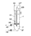
図2は本発明の電解水生成装置に組み込んで使用される酸化還元電位センサ1の一例を示すものである。この酸化還元電位センサ1は連続通水系に接続し、この通水系に通される水等の被検液の酸化還元電位を測定するために使用されるものであり、流入口118から流路37を通過して流出口119へと水が流れるようにしてあって、流路37中にガラスに封入された白金電極が配置してある。この白金電極を流入口118から流出口119へ流れる水(すなわち電解水)に浸漬される作用電極2とし、また飽和塩化カリウム溶液を内部液111とする銀塩化銀電極を比較電極112として、水の酸化還元電位を測定することができるのである。尚、流入口118から流出口119へ流れる水に内部液111が溶出して影響を及ぼすことを防ぐために、多孔質のアルミナセラミックによって液絡部116を形成するようにしてある。また作用電極2と比較電極112の間で測定された電位差はアンプ110によって増幅されて出力され、酸化還元電位として表示されるようになっている。アンプ110によって増幅された信号をAD変換してデジタル表示することも可能である。
【0029】
ここで、酸化還元電位センサ1の白金等の不溶性金属電極で形成される作用電極2は、棒状であっても板状であっても特に規制されるものではなく、形状や面積も可逆電池を形成し電位を確実に測定できればよく、特に規制されるものではないが、表面は酸化還元電位物質等の不純物による皮膜が形成されないようなものが好ましい。しかし、使用の初期の段階では白金等の作用電極2の表面は一部のみが酸化状態であるが、長期間空気中に放置すると表面の原子状酸素の量が増大し、また水の酸化還元電位測定を繰り返して行なうと酸化還元電位物質が表面から完全に脱離せず一部が吸着したままになり、作用電極2の表面に皮膜が形成される。このように作用電極2の表面に皮膜が形成されると測定のずれが発生したり応答性が緩慢になったりし、特に水道水レベルのイオン強度の低い水の測定の場合には測定の安定性が大きく低下する。
【0030】
そこで本発明では酸化還元電位センサ1の白金等の不溶性金属電極で形成される作用電極2を安全に洗浄することによって、作用電極2の表面を更新し、測定精度及び応答性、測定の安定性を回復させるようにしたものである。
すなわち、まず第1のステップとして溶存塩素を含む強酸性イオン水L1 を用い、図1(a)のように、この強酸性イオン水L1 に作用電極2を浸漬するかあるいは作用電極2にこの強酸性イオン水L1 を通水させ、作用電極2をこの強酸性イオン水L1 で処理する。強酸性イオン水L1 は、塩化ナトリウム(食塩)、塩化カルシウム、塩化カリウム等の強電解の無機塩素化合物を電解質として0.03〜0.3重量%程度添加した水を隔膜を有する電解槽(後述の図4、図5、図6参照)に通水し、一定の電圧を印加して電解することによって、溶存塩素を含むものとして陽極側から得ることができるものであり、酸化還元電位が900mV以上(上限は特に設定されないが1300mV以下であることが好ましい)でpHが3.5以下(下限は特に設定されないがpH2以上であることが好ましい)の強酸性イオン水であることが望ましい。このように溶存塩素を含む強酸性イオン水L1 で作用電極2を1〜10分間程度処理することによって、白金等の不溶性金属電極で形成される作用電極2の表面に形成された吸着不純物を酸化分解して除去することができる。
【0031】
しかしこの第1のステップで作用電極2に塩素の表面吸着が生じるので表面は完全には更新されていない。そこで第2のステップとして溶存酸素を含む弱酸性イオン水L2 を用い、図1(b)のように、この弱酸性イオン水L2 に作用電極2を浸漬するかあるいは作用電極2にこの弱酸性イオン水L2 を通水させ、作用電極2をこの溶存酸素を含む弱酸性イオン水L2 で処理する。弱酸性イオン水L2 は水道水の水質レベルの水を上記と同様に水を隔膜を有する電解槽に通水し、一定の電圧を印加して電解することによって陽極側から得ることができるものであり、酸化還元電位が500mV〜1000mVでpHが4〜6の酸性イオン水であることが望ましい。この酸性イオン水は溶存酸素濃度が高く酸化力が比較的高い水であり、溶存酸素を含む弱酸性イオン水L2 で作用電極2を1〜10分間程度処理することによって、作用電極2に表面吸着した塩素が酸素に置き換わり、白金等の作用電極2の表面が更新状態に近づく。
【0032】
しかし作用電極2の表面に原子状酸素の吸着が起こる場合もあり、まだ完全な初期表面状態に更新されているとはいえない。そこで第3のステップとして溶存水素を含むアルカリイオン水L3 を用い、図1(c)のように、このアルカリイオン水L3 に作用電極2を浸漬するかあるいは作用電極2にこのアルカリイオン水L3 を通水させ、作用電極2をこの溶存水素を含むアルカリイオン水L3 で処理する。アルカリイオン水L3 は水道水の水質レベルの水を上記と同様に水を隔膜を有する電解槽に通水し、一定の電圧を印加して電解することによって陰極側から得ることができるものであり、酸化還元電位が−200mV以下(下限は特に設定されないが−800mV以上であることが好ましい)でpHが9.5以上(上限は特に設定されないがpH12以下であることが好ましい)の強アルカリイオン水であることが望ましい。溶存水素を含む強アルカリイオン水L3 は還元性が高く、このアルカリイオン水L3 で作用電極2を1〜10分間程度処理することによって、白金等の作用電極2の表面の原子状酸素の量を減少させ、作用電極2の表面をほぼ完全に更新状態にすることができるものである。
【0033】
このようにして作用電極2の表面を洗浄更新することによって、作用電極2と水の酸化還元系との平衡の速度を増加させることができ、測定精度及び応答性、測定の安定性を回復させることができるものである。
次に、洗浄効果を実証する例を図2に示す酸化還元電位センサ1を用いて説明する。検定用の水としては、一定の電気伝導率に調整すると共に曝気処理した純水を溶媒とする0.001mMクロム酸カリウム−0.015mM硫酸鉄アンモニウム溶液(酸化還元電位仮基準液)を用いた。この検定用の水の理論的な酸化還元電位は310mVである。そしてまず作用電極2の表面が清浄な酸化還元電位センサ1を用いてこの検定用の水の酸化還元電位を測定し、これを初期測定値として表1に示すように記録した。この初期測定値の酸化還元電位は309mVであるが、これは誤差の範囲内である。次に、大阪市の市水を図2の矢印のように流路37に間欠的に1トン通水した後、上記の検定用の水の酸化還元電位を再度測定し、これを洗浄前測定値として表1に示すように記録した。この洗浄前測定値の酸化還元電位は382mVであり、理論値より大きく乖離した値を示している。この現象は、作用電極2である白金の表面の酸化還元物質等の不純物による測定ずれであると考えられる。そこで、酸化還元電位センサ1の作用電極2に対して上記の洗浄方法を実施した。
【0034】
すなわち、第1ステップの溶存塩素を含む強酸性イオン水L1 として、電解電圧8V、電解電流14A、食塩濃度0.1重量%の条件で水を電解して得られる酸化還元電位が1130mV、pH2.6の強酸性イオン水を用い、第2ステップの溶存酸素を含む弱酸性イオン水L2 として、電解電圧25V、電解電流5Aの条件で水を電解して得られる酸化還元電位が700mV、pH5.5の酸性イオン水を用い、第3ステップの溶存水素を含むアルカリイオン水L3 として、電解電圧35V、電解電流7Aの条件で水を電解して得られる酸化還元電位が−720mV、pH10.5の強アルカリイオン水をそれぞれ用い、各ステップでこれらの洗浄水をそれぞれ2リットル/minの通水量で2分間通水することによって行なった。
【0035】
このようにして酸化還元電位センサ1の作用電極2を洗浄処理した後、上記の検定用の水の酸化還元電位を再度測定し、これを洗浄後測定値として表1に示すように記録した。この洗浄後測定値の酸化還元電位は310mVであり、初期の状態に作用電極2の表面が回復していることが確認される。
【0036】
【表1】
【0037】
次に、制御回路系を一体に形成した酸化電極電位センサ1について説明する。酸化還元電位センサ1には制御回路系123が設けてあり、図3に示すように、制御回路系123には酸化還元電位センサ1で測定した酸化還元電位の値を記憶するようにEPROM等からなる記憶手段24と、酸化還元電位の値を比較する比較演算回路からなる比較手段25とが設けてある。記憶手段24と比較手段25にはそれぞれ酸化還元電位センサ1で測定された酸化還元電位の測定値のデータ信号が入力されるようになっており、また比較手段25から出力される信号に基づいてランプ等で形成される表示手段26を作動させるようにしてある。
【0038】
そしてこのものにあって酸化還元電位センサ1の作用電極2を洗浄した後、先述の酸化還元電位仮基準液など既知の水を用いてその酸化還元電位を測定する。記憶手段24はスイッチ127の操作で制御されるようにしてあり、このように洗浄した後の酸化還元電位センサ1で酸化還元電位を測定する際にスイッチ127をONさせると、この測定値が初期測定値として記憶手段24にメモリーされるようになっている。次に、酸化還元電位センサ1が使用されると経時的に作用電極2の表面に不純物が吸着等され、測定値にズレが生じてくる。そこで酸化電極電位センサ1を所定期間使用した後に、上記と同じ水を用いてその酸化還元電位を測定する。酸化電極電位センサ1で測定したこの測定値は比較手段25に入力され、記憶手段24に記憶されている初期測定値と比較演算される。そして比較手段25で比較演算された初期測定値と測定値の差が予め設定されている所定値を超えると、比較手段25から信号が出力され、例えば表示手段26のランプを点灯させるなどして酸化還元電位センサ1の洗浄を促すようになっている。このようにして、酸化還元電位センサ1の作用電極2の表面に不純物が吸着等されていて測定異常が発生すると、それを検知して洗浄を告知することができるものであり、精度が狂ったまま酸化還元電位センサ1を使い続けるというようなことを未然に防ぐことができるものである。
【0039】
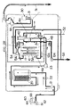
次に、上記のような酸化還元電位センサ1を組み込んだ電解水生成装置について説明する。図4は電解水生成装置の一例を示すものであり、電解槽10、逆洗ユニット131、切換弁132,133、電解質供給装置40として用いられるカルシウム剤添加用カートリッジ4、浄水装置20、そして酸化還元電位センサ1等をハウジング100に納めたものとして構成されている。
【0040】
電解槽10は陰極と陽極になる各一枚以上の電極13A,13Bとこの両者を仕切る電解隔膜11とを備えたもので、底部側に流入口14A,14Bを、上部側に吐出口15A,15Bを備えており、これら吐出口15A,15Bは、切換弁133を介して吐出管141,142に接続されている。ここにおいて、流入口14Aと吐出口15Aは一方の電極13Aを囲む電解隔膜11内の空間に連通し、流入口14Bと吐出口15Bとは他方の電極13Bを囲む空間に連通しているのであるが、流入口14Aは流入口14Bよりも細くされていて、電極13A側に流れ込む流量が電極13B側に流れ込む流量より1:3乃至1:4位の比率で少なくなるようにされている。また上記切換弁133は、吐出口15Aと吐出管141とを連通させる時、吐出口15Bと吐出管142とを連通させ、吐出口15Aと吐出管142とを連通させる時、吐出口15Bと吐出管141とを連通させるように電磁ロータリー弁もしくはモータ式切換弁で構成されている。
【0041】
浄水装置20は、活性炭からなる濾過材20aと中空糸膜からなる濾過材20bとを収容したカートリッジを装着するものとして形成されるものであり、また逆洗ユニット131に取り外し自在に接続して、取り替えができるようにしてある。逆洗ユニット131は浄水装置20内の濾過材20a,20bの目詰まりを、いったん浄水装置20に通した水を切換弁132から供給される水圧によって浄水装置20に逆流させることで解消するためのものであり、切換弁132は電解槽10への水の供給状態とこの逆流状態とを切り換えるためのものである。
【0042】
また逆洗ユニット131から電解槽10の流入口14A,14Bの間に流量計146、電磁弁147、逆止弁148が設けられており、電磁弁147から流入口14Aに至る配管の途中にカルシウム添加用カートリッジ4が設けてある。カルシウム添加用カートリッジ4はカルシウム製剤を収容して形成されるものであり、配管に通水される水にカルシウムを溶解させて水中のカルシウム分を増量させるためのものである。このカルシウム添加用カートリッジ4は配管に接続して、取り替えができるようにしてある。そして上記逆止弁148は排水口149につながっており、上流側の原水圧がかかっている時は閉じているものの、水圧がかからなくなった時に開いて、電解槽10内の水及び配管内の残水を排水口149から排出するようになっている。
【0043】
さらに、電解槽10と吐出管142との間の配管の途中に酸化還元電位センサ1が接続してある。酸化還元電位センサ1としては制御系の構造などを図2に示すものと同様に形成したものが使用されるものであり、電解槽10で生成された電解イオン水が酸化還元電位センサ1を通過する際に、電解イオン水の酸化還元電位物質の濃度に応じて白金等の作用電極2で半電池反応が起こり、これを比較電極112との電位差として出力してアンプ110で増幅し、そして増幅された出力値に基づいて制御回路でAD変換されて、酸化還元電位をデジタル表示するようになっている。
【0044】
次に、水道水から電解イオン水を取り出すときの水の流れについて説明する。水路切換装置61でカラン60の水を切換弁132側へ切り換えると、水は切換弁132を介して浄水装置20を通過し、流入口14A,14Bから電解槽10に入り、電解槽10内で電解される。電解槽10の各電極13A,13Bへの通電は流量計146から得られる水の流れの情報に基づいて開始される。
【0045】
そしてアルカリイオン水を得たい旨の指示がなされているならば、電解槽10の電極13Bが陰極に、電極13Aが陽極になるように電解電圧の極性が決められる。これにより、吐出口15Bからアルカリイオン水が、吐出口15Aから酸性イオン水が得られ、吐出管142からアルカリイオン水が、吐出管141から酸性イオン水が吐出される。逆に、酸性イオン水を得たい旨の指示がなされているならば、電解槽3の電極13Bが陽極に、電極13Aが陰極になるように電解電圧の極性が決められる。これにより、吐出口15Bから酸性イオン水が、吐出口15Aからアルカリイオン水が得られ、吐出管142から酸性イオン水が、吐出管141からアルカリイオン水が吐出される。吐出管142から吐出されるこれらのイオン水は、酸化還元電位センサ1を通過して酸化還元電位が測定され、表示される。
【0046】
また、食塩などの強電解質の無機塩素化合物を添加した水の電解イオン水を得るには、カルシウム添加用カートリッジ4の代わりに、このカルシウム添加用カートリッジ4と同じハウジングで形成したカートリッジ5に食塩などの無機塩素化合物等を充填したものを用いて配管に接続する(請求項10)。そして電解槽10の電極13Bが陰極に、電極13Aが陽極になるように電解電圧の極性を決定する。また切換弁133は吐出口15Bが吐出管141に、吐出口15Aが吐出管142に接続されるように切り換えられており、吐出管142から強酸性イオン水が、吐出管141からアルカリイオン水が吐出される。カートリッジ5から添加する食塩などの無機塩素化合物の添加量は、水中の食塩などの無機塩素化合物の濃度が0.03〜0.3重量%になるようにするのが好ましく、添加量がこのようになる構造にカートリッジ5を形成してある。
【0047】
食塩などの強電解質の無機塩素化合物を添加した水を電気分解するには、このようにカルシウム添加用カートリッジ4の代わりに電解質添加用のカートリッジ5に食塩などの無機塩素化合物を充填したものを用いる他に、浄水装置20の濾過材を収容したカートリッジの代わりに、食塩などの無機塩素化合物(あるいはこれとクエン酸などの有機酸を混合したもの)を充填したカートリッジを浄水装置20に入れ換えるようにして、無機塩素化合物を水に添加するようにすることもできる(請求項12)。さらに、カルシウム添加用カートリッジ4にカルシウム剤の代わりに電解質として食塩などの無機塩素化合物を充填することによって、無機塩素化合物を水に添加するようにすることもできる(請求項11)。
【0048】
そして電解水生成装置は、図示を省略する操作パネルの操作部を操作してpH切り換えスイッチを切り換えることによって、pHレベルが異なるアルカリイオン水や酸性イオン水を電解槽10で生成することができるように電解電圧を制御して、複数のモードで運転できるようになっている。例えば、アルカリイオン水がレベル1でpH8.5、レベル2でpH9.0、レベル3でpH9.5、レベル4でpH10.5の4段階のpHレベルの各モードによって、酸性イオン水がレベル1でpH5.5、レベル2でpH2.9の2段階のpHレベルの各モードによって運転できるようにしてあり、さらに電解槽10に電解電圧を印加しない浄水モードによっても運転できるようにしてある。これらのpHの異なる各電解イオン水(浄水も含む、以下同じ)はそれぞれ酸化還元電位も当然異なるが、pHが高い程、酸化還元電位は低い値を示し、pHが低い程、酸化還元電位は高い値を示す。
【0049】
ここで、酸化還元電位センサ1には既述の図3の制御回路系123が設けられており、洗浄後の酸化還元電位センサ1で測定した通水初期の電解水の酸化還元電位を初期測定値として記憶手段25にメモリーし、電解水生成時に電解槽10で生成された電解イオン水の酸化還元電位を酸化還元電位センサ1で測定し、この電解水生成時に酸化還元電位センサ1で測定した酸化還元電位の値と、記憶手段24にメモリーした初期測定値とを比較手段25で比較し、比較手段25による比較の差の値が所定値以上のときに、表示手段6で酸化還元電位センサ1の洗浄を促すようにしてある(請求項5)。
【0050】
そして電解水生成装置を同一水質で使用するときには、同じpHのイオン水は同じ酸化還元電位を示すので、pHレベルの異なるアルカリイオン水やpHレベルの異なる酸性オイン水や浄水を生成する各モードにおいてそれぞれ、洗浄した後の酸化還元電位センサ1で測定したイオン水の酸化還元電位を初期測定値として記憶手段24にメモリーし、電解イオン水を生成する運転をしている際に酸化還元電位センサ1で測定した電解イオン水の酸化還元電位と記憶手段24にメモリーした初期測定値とを比較手段25で比較するようにしてあり、この比較の差が例えば100mV以上となれば、酸化還元電位センサ1の作用電極2の表面に不純物が付着等して測定の精度異常が生じたものと判断することができ、このときには酸化還元電位センサ1の洗浄を促すように表示手段26のランプを点灯させるようにしてある。従って、電解水生成装置をどのモードで使用していても、酸化還元電位センサ1の洗浄が必要なことを知って酸化還元電位センサ1を洗浄することができ、常に正しい酸化還元電位の測定値を表示させながら電解水生成装置を使用することができるものである(請求項6,7)。
【0051】
このように、各モードにおいて酸化還元電位の初期測定値を記憶手段24にメモリーさせるにあたって、酸化還元電位のこの初期の測定を精度良く行なうためには次のモードの順に測定を行なう必要がある。すなわち、アルカリイオン水のように溶存水素が多い水の場合は、酸化還元電位センサ1の白金等の作用電極2の表面に水素が吸着し易いが、水素は容易に表面から離脱し易いために、この後に他のモードの水の酸化還元電位を測定する際に与える影響は小さい。これに対して酸性イオン水のような溶存酸素や溶存塩素が多い水の場合は、酸化還元電位センサ1の白金等の作用電極2の表面に酸素や塩素が吸着すると水素よりも脱離し難いために、この後に他のモードの水の酸化還元電位を測定する際に与える影響が大きくなる。そこで、まずアルカリイオン水を生成する運転モードで酸化還元電位を測定し、しかも測定の前液の影響を出来る限り避けるためにアルカリイオン水のなかでもpHレベルの高いものから順に低いものへと移行して酸化還元電位を測定し、各モードでのこの初期測定値を順に記憶手段24にメモリーさせ、次に浄水モードで測定して酸化還元電位の初期測定値を順に記憶手段24にメモリーさせ、この後、酸性イオン水を生成する運転モードで酸化還元電位を測定し、しかもここでも測定の前液の影響を出来る限り避けるために酸性イオン水のなかでもpHレベルの高いものから順に低いものへと移行して酸化還元電位を測定し、各モードでのこの初期測定値を順に記憶手段24にメモリーさせる。このようにして各モードでの酸化還元電位の初期測定値を精度良く測定して記憶手段24にメモリーさせることができ、以降の電解水生成運転時の酸化還元電位の実測値と比較手段25で比較して、酸化還元電位センサ1の洗浄の必要性を精度高く検知することができるものである(請求項8)。
【0052】
前記の例の場合では、まずアルカリイオン水のレベル4のpH10.5の運転モードで酸化還元電位の初期測定値を測定し、以下、レベル3のpH9.5、レベル2のpH9.0、レベル1のpH8.5の各運転モードの順に酸化還元電位の初期測定値の測定を行ない、次に浄水モードで酸化還元電位の初期測定値を測定した後、酸性イオン水のレベル2のpH2.9、レベル1のpH5.5の各運転モードの順に酸化還元電位の初期測定値の測定を行ない、これらの初期測定値をそれぞれ記憶手段24に個別にファイルしてメモリーするようにしてある。ここで、酸化還元電位センサ1で測定するにあたって、2秒以上安定した酸化還元電位の値を各モードでの初期測定値として判断してメモリーするように記憶手段24を形成するのが好ましい。
【0053】
そして記憶手段24にメモリーされた各モードの酸化還元電位の初期測定値と、電解水生成の各モードで運転している際の酸化還元電位の測定値とを比較手段25の演算回路で常時比較できるようになっており、上記のように初期測定値に対してこの測定値が100mV以上ずれると異常と判断するが、その測定の際の水の水質や水の流量の影響で初期測定値とのズレが一過性で生じることがあるリスクを避けるために、連続10回同じモードの運転で100mV以上のずれが発生した場合にのみ、表示手段26を作動させるようにしてある。
【0054】
上記のようにして酸化還元電位センサ1の洗浄の必要を検知することができるが、電解水生成装置には図1に示す洗浄方法を自動であるいは手動で行なわせる手段が設けられている。すなわち、まず第1ステップの洗浄を行なうにあたっては、食塩等の無機塩素化合物を充填したカートリッジ5をカルシウム添加用カートリッジ4と交換するか、あるいは食塩等の無機塩素化合物を充填したカートリッジ8を浄水装置20に交換して入れて、電解槽10に通水される水に無機塩素化合物を濃度が0.03〜0.3重量%となるように添加する。そして電解槽10の電極13Bが陰極に、電極13Aが陽極になるように電解電圧の極性を決定して10〜20Vの直流電圧を印加することによって、陽極の電極13A側から酸化還元電位が900mV以上でpHが3.5以下の強酸性イオン水を得ることができる。このとき切換弁133は吐出口15Bが吐出管141に、吐出口15Aが吐出管142に接続されるように切り換えられており、吐出管142から強酸性イオン水が、吐出管141からアルカリイオン水が吐出されるようになっている。従って、この強酸性イオン水は酸化還元電位センサ1に連続通水され、作用電極2を溶存塩素を含む強酸性イオン水で第1ステップの洗浄を行なうことができる。この第1ステップの際の酸化還元電位センサ1への強酸性イオン水の通水時間は1〜5分程度が好ましい。
【0055】
次に第2ステップの洗浄を行なうにあたっては、カルシウム添加用カートリッジ4や浄水装置20を戻し、水道水の水質レベルを有する水を通水し、電解槽10の電極13Bが陽極に、電極13Aが陰極になるように電解電圧の極性を決定して10〜40Vの直流電圧を印加することによって、陽極の電極13B側から酸化還元電位が500mV〜100mV以上でpHが4〜6の酸性イオン水を得ることができる。このとき切換弁133は、吐出管142から酸性イオン水が、吐出管141からアルカリイオン水が吐出されるように切り換えられている。従って、この酸性イオン水は酸化還元電位センサ1に連続通水され、作用電極2を溶存酸素濃度が高く酸化力が比較的高い酸性イオン水で第2ステップの洗浄を行なうことができる。この第2ステップの際の酸化還元電位センサ1への酸性イオン水の通水時間は1〜5分程度が好ましい。
【0056】
次に第3ステップの洗浄を行なうにあたっては、引き続いて水道水の水質レベルを有する水を通水し、電解槽3の電極13Bが陰極に、電極13Aが陽極になるように電解電圧の極性を決定して20〜40Vの直流電圧を印加することによって、陰極の電極13B側から酸化還元電位が−200mV以下でpHが9.5以上の強アルカリイオン水を得ることができる。このとき切換弁33は、吐出管142から強アルカリイオン水が、1吐出管41から酸性イオン水が吐出されるように切り換えられている。従って、この強アルカリイオン水は酸化還元電位センサ1に連続通水され、作用電極2を溶存水素濃度が高く還元力が高い強アルカリイオン水で第3ステップの洗浄を行なうことができる。この第3ステップの際の酸化還元電位センサ1への強アルカリイオン水の通水時間は1〜5分程度が好ましい。
【0057】
このように3段階のステップで酸化還元電位センサ1の白金等の作用電極2を洗浄することによって、作用電極2の表面を更新することができるものであり、作用電極2と被検液の酸化還元系との平衡の速度を増加させることができ、電解槽10で生成されるイオン水の酸化還元電位の安定した測定が可能になるものである。
【0058】
次に、上記の洗浄効果を実証する例を説明する。河川の水を原水とする導電率12mS/mの水道水を使用し、まず洗浄直後の酸化還元電位センサ1を用いて各モードでイオン水の酸化還元電位を測定し、これを各モードの初期測定値として記憶手段24に記憶させた(この初期測定値を表2に示す)。次に、同じ水道水を1500リットル通水した後の、アルカリイオン水のpH9.5のモードの運転の際に酸化還元電位を測定したところ、初期測定値が−150mVであったものが連続10回20mVの測定値(これを洗浄前測定値として表2に示す)となり、初期測定値との差が基準の100mVを上回ったために、表示手段26の洗浄ランプが点灯した。洗浄を行なう前に、他の各モードでも同様に酸化還元電位を測定したところ、いずれのモードでも測定値(これを洗浄前測定値として表2に示す)は初期測定値と基準以上にずれており、よってどのモードで使用していても酸化還元電位センサ1の測定異常を検知できることが確認される。
【0059】
このようにして酸化還元電位センサ1の測定異常が表示手段26で表示された後、酸化還元電位センサ1の作用電極を既述の第1ステップ〜第3ステップの3段階の電解処理による方法で洗浄した。すなわち、まず食塩を充填したカートリッジ5をカルシウム添加用カートリッジ4と交換して、電解槽10に通水される水に食塩を濃度が0.1重量%となるように添加すると共に、電解槽10の電極13Bが陰極に、電極13Aが陽極になるように電解電圧の極性を決定して電解電圧10V、電解電流15Aの条件で電解し、陽極の電極13A側から生成される酸化還元電位が1150mV、pHが2.5の強酸性イオン水を酸化還元電位センサ1に2リットル/minの通水量で5分間通水することによって、第1ステップの洗浄を行なった。次に、カルシウム添加用カートリッジ4を戻し、電解槽10の電極13Bが陽極に、電極13Aが陰極になるように電解電圧の極性を決定して電解電圧22V、電解電流4Aの条件で電解し、陽極の電極13B側から生成される酸化還元電位が650mVでpH5.7の弱酸性イオン水を酸化還元電位センサ1に2リットル/minの通水量で5分間通水することによって、第2ステップの洗浄を行なった。次に、電解槽3の電極13Bが陰極に、電極13Aが陽極になるように電解電圧の極性を決定して電解電圧40V、電解電流8Aの条件で電解し、陰極の電極13B側から生成される酸化還元電位が−760mVでpH10.7の強アルカリイオン水を酸化還元電位センサ1に2リットル/minの通水量で5分間通水することによって、第3ステップの洗浄を行なった。
【0060】
このようにして洗浄を行なった後の酸化還元電位センサ1を用いて各モードでイオン水の酸化還元電位を測定し、この測定値を洗浄後測定値として表2に示した。表2にみられるように、各モードにおいて洗浄後測定値は初期測定値に殆ど誤差の範囲内で近くなっており、洗浄による効果が確認される。
【0061】
【表2】
【0062】
上記の図4の実施の形態の電解水生成装置では、記憶手段24と比較手段25と表示手段126を制御回路系123として一体に組み込んだ酸化還元電位センサ1を用いるようにしたが、勿論このものに限定されるものではないのはいうまでもない。
図5乃至図12に示す実施の形態の電解水生成装置では、酸化還元電位センサ1をpHセンサ31と一体化して水質測定装置30を形成し、この水質測定装置30を電解水生成装置に組み込むようにしてあり、また記憶手段24や比較手段25は図11(a)及び図12に示す制御部71(マイコン)に具備させるようにしてある。具体的には、記憶手段24はメモリ74として、比較手段25は比較部71cとして具備してあり、表示手段26は表示部72bとして具備してある。そしてこの装置では既述の請求項5、請求項6、請求項7、請求項8の動作は、制御部71による制御で同様におこなわれるようにしてある。
【0063】
図5、図6に示すこの電解水生成装置は、アルカリイオン整水器及び強酸化水生成装置の機能を併せ持つように形成したものである。基本的には従来例で示した図17、図18と同じ構成を有しており、電解槽10および浄水装置20を備え、水道水などの原水が浄水装置20に通水されて浄化され、浄水装置20から流出する浄水が電解槽10において電解され、アルカリ性水と酸性水とを連続的に生成させるものである。ここでは原水を水道水としており、カラン60に取り付けた水路切換装置61を通して浄水装置20に水道水が導かれる。水路切換装置61は2つのポート62,63を備え、切換レバー64の操作により水道水をそのまま吐出させる状態と浄水装置20に導く状態とを切り替えることができるようになっている。
【0064】
また、電解槽10で生成された電解水の流出経路にはアルカリ性水の水質を電気的に測定する水質測定装置30が配置されている。水質測定装置30は電気化学的原理により酸化還元電位、pH、特定のイオンのイオン濃度を測定するものや電気伝導率を測定するものであり、前記のように、酸化還元電位センサ1とpHセンサ31とを備えている。
【0065】
浄水装置20への原水の流路上には、サーミスタよりなる温度センサ21と、定流量弁22とが配置される。温度センサ21は流入する原水の温度を検出し、所定温度以上の湯が通水されたときには後述する制御部71を介して音響的に警報を発するようにしてある。また、定流量弁22は過剰な水圧が浄水装置20以降の水路に作用するのを防止するために設けてある。浄水装置20は、活性炭(抗菌処理されている)からなる濾材と中空糸膜からなる濾材とを収めたカートリッジを内部に備え、カートリッジの交換によって濾材を交換することができるように構成されている。
【0066】
電解槽10はその内部に、電解隔膜11に囲まれた第1の電極室12Aと、電解隔膜11の外側である第2の電極室12Bとを備え、各電極室12A,12B内にはそれぞれ電極13A,13Bが配置される。また、各電極室12A,12Bは下端部にそれぞれ流入口14A,14Bを備え、また上端部にそれぞれ流出口15A,15Bを備える。流入口14Aおよび流出口15Aは流入口14Bおよび流出口15Bよりも開口面積が小さく形成され、電極室12Aに流入する流量と電極室12Bに流入する流量との割合が1:3ないし1:4程度になるようにしてある。かつまた、電極室12A,12Bの容積も電極室12Aのほうが電極室12Bよりも小さく形成してある。これは、各電極室12A,12Bにおいて生成される電解水の濃度に差をもたせるためである。
【0067】
浄水装置20と電解槽10との間の流路上には流量センサ23と電解質供給装置40とが配置される。電解質供給装置40の内部の流路については後述するが、電解質供給装置40の内部で2系統に分流され、その一方は流入口14Aより第1の電極室12Aに導入され、他方は流入口14Bより第2の電極室12Bに導入される。また、流入口14Bへの流路は電磁弁である排水弁124を通して吐出管53に接続されている。吐出管53は基本的には使用に供されることのない不要な水を廃棄する目的で設けられているが、必要に応じて使用することができる。
【0068】
電解槽10の流出口15A,15Bは、流路切換弁54を通して流出管53および水質測定装置30に接続され、流出口15Bを流出管53に接続するとともに流出口15Aを水質測定装置30に接続する状態と、流出口15Bを水質測定装置30に接続するとともに流出口15Aを流出管53に接続する状態とを切り換えることができるようにしてある。水質測定装置30は流路切換弁55を介して吐出管51,52に接続され、水質測定装置30を通った電解水はいずれかの吐出管51,52から選択的に吐出される。流路切換弁54,55は電磁切換弁もしくはモータ式切換弁により構成される。流路切換弁54,55は連動するように制御される。すなわち、図5のように流路切換弁54により流出口15Aと吐出管53とを連通させるときには、流路切換弁55は流出口15Bと吐出管51とを連通させるようになっている。また、図6のように流路切換弁54により流出口15Bと吐出管53とを連通させるときには、流路切換弁55は流出口15Aと吐出管52とを連通させるようになっている。つまり、吐出管53からは必ず電解水が吐出され、吐出管51と吐出管52とはいずれか一方のみから電解水が選択的に吐出されるのである。
【0069】
上述したサーミスタ21から流路切換弁54,55までの流路上の部材はハウジング100に収納され、ハウジング100からは3本の吐出管51,52,53が引き出される。ここに、吐出管51にはフレキシブルパイプを用いる。また、カラン60からの原水を取り込むためのホースもハウジング100から引き出される。
【0070】
ところで、水質測定装置30は上述のように酸化還元電位センサ1とpHセンサ31とを備えるものであり、図7に示すように、pHセンサ31は、塩化カリウムの飽和水溶液に銀−塩化銀電極を浸漬した比較電極33と、特殊ガラス電極に塩化カリウムの飽和水溶液を満たした作用電極34と、液絡部35とを備えるものであり、ハウジング36に設けた流路37に作用電極34および液絡部35を臨ませることにより流路を通過する水の水素イオン濃度に比例した電圧が比較電極33と作用電極34との間に起電力として発生するようになっている。この起電力は適宜増幅率の増幅器を用いて増幅されることによりpH値に応じた0〜5Vの電圧に変換され、A/D変換が施された後に後述する制御部71に入力される。
【0071】
また、酸化還元電位センサ1は、白金のような不溶性電極をガラスに封入した作用電極2を備え、作用電極2をハウジング36内の流路37に臨ませてある。酸化還元電位センサ1の比較電極はpHセンサ31の比較電極33を共用して用いており、比較電極33と作用電極2との間の相対電位差を酸化還元電位として検出する。検出された電位差は適宜増幅率の増幅器により増幅され酸化還元電位に応じた0〜5Vの範囲の電圧に変換され、pHセンサ31と同様にA/D変換が施された後に後述する制御部71に入力される。
【0072】
電解質供給装置40は、図8に示すように、電解質43を入れた非金属材料よりなる筒状の容器42a,42bをジャケット41内に装着する構成を有している。本実施形態ではアルカリイオン整水器と強酸化水生成装置のどちらの機能として用いるかに応じて電解質43の種類が選択される。つまり、飲用であるアルカリイオン水や洗顔用などの酸性イオン水を生成するときには乳酸カルシウムなどカルシウムを添加するカルシウム剤を電解質43aとして用い、強酸化水を生成する際には塩化ナトリウム(又は食塩)、塩化カルシウム、塩化カリウムなどの無機塩素化合物、またはこれらの混合物を電解質43bとして用いる。そこで、電解質43の種類に応じて形状の異なる容器42a,42bをジャケット41に収納し、使用する容器42a,42bに応じてジャケット41の中での流路が変更されるようにしてある。
【0073】
具体的に説明すると、ジャケット41は水の流入する1本の導入路管41aと2本の排出路管41b,41cとを備え、導入路管41aと一方の排出路管41bとの間はバイパス路管41dを通して連通している。一方、アルカリイオン水を生成する際に用いる容器42aは、図9(a)のように両排出管路41b,41cにそれぞれ連通する開口44a,44bが形成されている。また、強酸化水を生成する際に用いる容器42bは、図9(b)のように両排出路管41b,41cにそれぞれ連通する開口44a,44bに加えて底壁の中央部から延長された導入筒44cを備える。導入筒44cは導入路管41aに挿入したときに先端部がバイパス路管41dを閉塞する長さを有する。
【0074】
そして、アルカリイオン水、酸性イオン水、強酸性イオン水などを生成する際には、図8(a)のように乳酸カルシウムなどのカルシウム剤を電解質43aとして入れた容器42aをジャケット41に装着する。この状態では、流量センサ23を通り導入路41aからジャケット41に導入された浄水はバイパス路管41dを通して排出路管41bに送られるとともに、バイパス路管41dを通して容器42aに送られたのち排出路管41cから排出される。すなわち、排出路管41bに連通する電解槽10の流入口14Bに導かれるとともに、電解質43aを通り排出路41cを通って電解槽10の流入口14Aに導かれる。つまり、この状態においては、電解槽10の流入口14Aには電解質43aを通した水が導入され、流入口14Bには電解質43aを通らない水が導入されることになる。
【0075】
一方、強酸化水を生成する際には、図8(b)のように無機塩素化合物を電解質43bとして入れた容器42bをジャケット41に装着する。このとき、導入筒44cによってバイパス路管41dが閉塞されるから、導入路管41aからジャケット41に流入する水はバイパス路管41dへの流入が禁止されて導入筒44cを通して容器42bに直接導入され、その後、排出路管41bおよび排出路管41cに分流されることになる。つまり、排出路管41bに接続された電解槽10の流入口14Bと、排出路管41cに接続された電解槽10の流入口14Aとにはそれぞれ容器42b内の電解質43bに接触した水が導入される。
【0076】
ここにおいて、ジャケット41の外側面には検知手段となる高周波発振型の近接スイッチ45が取り付けられており、容器42bには識別手段となる帯状に形成した検出用金属片46が取り付けられている。しかして、容器42bをジャケット41に装着すれば、近接スイッチ45において容器42bの装着が検出されるから、検出用金属片46を識別手段として容器42a,42bの種別を識別させることができる。したがって、近接スイッチ45の出力を後述する制御部71に与えることにより、アルカリイオン水、酸性イオン水、強酸性イオン水などを生成する状態か、強酸化水を生成する状態かを制御部71に指示することができる。このように本実施形態においては、識別手段である検出用金属片46と検知手段である近接スイッチ45とで電解質43の種類を識別して検知信号を制御部71に送る識別検知手段が構成してある。
【0077】
近接スイッチ45は、周知のものであって、たとえば図10に示すように、検出コイル45aに対して高周波発振回路45bから高周波電流を与え、金属物体Xが接近したときに生じる検出コイル45aのインピーダンス変化を高周波発振回路45bの発振出力の変化により検出するものが知られている。すなわち、金属物体Xが近接すれば、高周波発振回路45bは発振を停止するから、高周波発振回路45bの出力を検波回路45cで検波し波形成形回路45dで波形成形することにより、高周波発振回路45bの発振の有無に応じた信号を波形成形回路45dから出力し、これを外部回路を駆動するための出力回路45eを通して取り出すのである。容器42a,42bの種別を識別する手段(つまり電解質43の種類を識別検知する識別検知手段)としては、近接スイッチ45に代えて磁気センサ(リードスイッチやホール素子)を設け、検出用金属片46に代えて永久磁石を設けてもよい。また、マイクロスイッチのような機械的スイッチを用いて容器42a、42bの種別を判別するようにしてもよい。
【0078】
ところで、この近接スイッチ45からの出力信号は、図11(a)、図12に示す制御部71により制御される。この制御部71は、1チップマイクロコンピュータ(マイコン)を用いて構成される。制御部71には操作表示部72が接続され、操作表示部72は図11(b)に示すように、電源スイッチ72a1のほか、アルカリイオン水、酸性イオン水の生成の選択やpHの調整などの各種操作を行なうためのスイッチ群72aと、液晶表示器72b1および発光ダイオードよりなるランプ群を備えた表示部72bとを備える。
【0079】
図11(b)に示すように、スイッチ群72aの中には電源スイッチ72a1、アルカリイオン水生成モード用のスイッチ72a3、酸性イオン水生成モード用兼強酸性イオン水生成モード用のスイッチ72a5、浄水モード用のスイッチ72a4、強酸化水生成モード用のスイッチ72a2等が設けてある。
表示部72bとしては上記アルカリイオン水生成モード用のスイッチ72a3、酸性イオン水生成モード用兼強酸性イオン水生成モード用のスイッチ72a5、浄水モード用のスイッチ72a4、強酸化水生成モード用のスイッチ72a2に対応して発光ダイオードにより構成した選択ランプが設けてある。すなわち、実施形態においてはアルカリイオン水生成モード用のスイッチ72a3は1回操作する場合、2回操作する場合、3回操作する場合、4回操作する場合でそれぞれ4種類のアルカリイオン水を選択して生成できるようになっており、このアルカリイオン水生成モード用のスイッチ72a3の4段階の操作に対応して4つのアルカリイオン水生成用の選択ランプ72b7、72b6、72b5、72b4が設けてあり、アルカリイオン水生成モード用のスイッチ72a3の各操作段階に応じてそのいずれかに対応したアルカリイオン水生成用の選択ランプ72b7、72b6、72b5、72b4のいずれかが点灯して目的とする段階のアルカリイオン水生成モードであることを知らせるようになっている。また、酸性イオン水生成モード用兼強酸性イオン水生成モード用のスイッチ72a5に対応して酸性イオン水生成モード用の選択ランプ72b9と強酸性イオン水生成モード用の選択ランプ72b10とが設けてあり、酸性イオン水生成モード用兼強酸性イオン水生成モード用のスイッチ72a5を1回操作すると酸性イオン水生成モード用の選択ランプ72b9が点灯し、2回操作すると強酸性イオン水生成モード用の選択ランプ72b10が点灯するようになっていて、それぞれ酸性イオン水生成モード又は強酸性イオン水生成モードであることを知らせるようになっている。また、浄水モード用のスイッチ72a4に対応して浄水モード用の選択ランプ72b8が設けてあり、浄水モード用のスイッチ72a4をオンに操作した場合に浄水モード用の選択ランプ72b8が点灯して、浄水モードであることを知らせるようになっている。また、強酸化水生成モード用のスイッチ72a2に対応して強酸化水生成モード用の選択ランプ72b3が設けてあり、強酸化水生成モード用のスイッチ72a2をオンに操作した場合強酸化水生成モード用の選択ランプ72b3が点灯して、強酸化水生成モードであることを知らせるようになっている。なお図11(b)中72b2は電源スイッチ72a1がオンの時に点灯し、オフの時消灯するランプである。
【0080】
また、図11(b)に示すように、液晶表示器72b1には添加した電解質の種類に応じて表れる表示部分を備え、近接スイッチ45からの出力信号が制御部71に送られると、液晶表示器72b1に電解質43の種類に応じた表示が表れる。ここで、本実施形態においては、強酸化水生成用の電解質43bを識別検知手段により識別検知した場合にのみ液晶表示器72b1にその旨の表示(例えば図11(b)の「食塩添加中」という表示)がなされるようになっており、強酸化水生成用以外の電解質43を識別検知手段で識別検知した場合には液晶表示器72b1に何も表示されないようになっており、このことにより、電解質43の種類が何も表示されない状態では強酸化水生成用の電解質43b以外の電解質43を添加している場合か、あるいは無添加の場合であるかのいずれかであることが知られるようになっている。
【0081】
そして、強酸化水を生成するための電解質43bを識別検知手段により識別検知した場合(つまり、近接スイッチ45により強酸化水生成用の電解質43bを入れた容器42bを検知した場合)には近接スイッチ45からの出力信号が制御部71に送られると、強酸化水を生成するための電解質43bを検知したことが報知手段である液晶表示器72b1により表示され(実施形態においては前述のように、電解質43bとして食塩を添加した時には、「食塩添加中」という文字が液晶表示器72b1に表れる)、同時に流路切換弁54、55が切り換えられ、図6のような流路となる。また、識別検知手段により強酸化水を生成するための電解質43bの識別検知信号が制御部71に入力された場合には、強酸化水生成モード以外の電解水生成モードを受付不能となるように制御部71により制御されるようになっている(つまり、強酸化水生成モード用のスイッチ72a2以外の他のモードのスイッチは受付不能となる)。
ここで、浄水モードや各種電解水を生成するモードを選択するための選択スイッチ72a3〜72a5を新たにオンする迄は前回の運転モードを表示する選択ランプが点灯するように制御部71により制御されるようになっているが、しかしながら、識別検知手段により強酸化水を生成するための電解質43bの識別検知信号が制御部71に入力された場合のみは、その後に強酸化水を生成するための選択スイッチ72a2を操作するまでの間、前回の運転モードを表示する選択ランプを消灯するように制御されるようになっている。また、すでに述べたように識別検知手段により強酸化水を生成するための電解質43bの識別検知信号が制御部71に入力された場合は液晶表示器72b1に当該電解質43bが添加されたことを報知するようになっているが、ブザーその他の音、あるいは音声で報知するようにしてもよい。
【0082】
上述のように、識別検知手段により強酸化水を生成するための電解質43bの識別検知信号が制御部71に入力されると、流路切換弁54、55が切り換えられ、図6のような流路となり、また、強酸化水生成モード用のスイッチ72a2以外の他のモードのスイッチ、すなわち、アルカリイオン水生成モード用のスイッチ72a3、酸性イオン水生成モード用兼強酸性イオン水生成モード用のスイッチ72a5、浄水モード用のスイッチ72a4がいずれも受付けられないように制御部71により制御されるようになっていると共に、前回の運転モードを表示する選択ランプも消灯し、更に、強酸化水生成用の電解質43bが添加されたことを報知手段により報知するので、強酸化水生成用の電解質が添加されたことが使用者に判り、また、強酸化水生成モード以外のモードを受け付けないことでモードに適さない電解質43が添加された場合の誤生成を防止することができ、また、食塩水が飲用側の吐水として出てくることはなく、飲用側のスイッチは受け付けないので誤って強酸化水や食塩入りの電解水を飲むことはない。
【0083】
一方、上記のように識別検知手段により強酸化水を生成するための電解質43bの識別検知信号が制御部71に入力されると、強酸化水生成モード用のスイッチ72a2以外の他のモードのスイッチは受付けないようになっているが、逆に強酸化水生成用の電解質43b以外の電解質43を添加した場合や、電解質43を添加しなかった場合(無添加の場合)にも識別検知手段により識別検知されて制御部71に出力され、この場合にはスイッチ群72aのうち強酸化水生成モード用のスイッチ72a2は受付けず、他のスイッチであるアルカリイオン水生成モード用のスイッチ72a3、酸性イオン水生成モード用兼強酸性イオン水生成モード用のスイッチ72a5、浄水モード用のスイッチ72a4を受付けることができるように制御部71により制御されるようになっている。
【0084】
また、電解槽10に設けた各電極13A、13Bに印加する電圧の極性や大きさも、制御部71により制御される。この場合、すでに述べたように、強酸化水を生成する電解質43bを添加した場合のみは、該添加を識別検出手段で検出することで自動的に流路切換弁54、55の切換えを行い、その後、強酸化水生成モード用のスイッチ72a2を操作した時に、電極13A、13Bへの印加電圧の大きさや極性を制御するものであり、他の電解質43を添加した場合は、強酸化水生成モード以外の他の種々のモード(アルカリイオン水生成モード、酸性イオン水生成モード、強酸性イオン水生成モード、浄水モード)のうち、任意のモード用のスイッチを操作した時、操作したモードに対応して電極13A、13Bへの印加電圧の大きさや極性、流路切換弁54、55の切換、排水弁124の開閉などを制御するものである。
【0085】
また、上述した水質測定装置30と流量センサ23からの出力によっても、各電極13A、13Bに印加する電圧の極性や大きさや、流路切換弁54、55の切換、排水弁124の開閉などが制御される。すなわち、制御部71に設けた比較部71aにおいて、水質測定装置30により測定したpHをあらかじめ設定した設定値と比較し、PWM制御を行なうスイッチング電源73をフィードバック制御することにより、pHが目標値に一致するように電極13A,13Bに印加する電圧を調節する。また、電極13A,13Bへの印加電圧の極性はリレー接点r1 ,r2 により切り換えられる。
【0086】
次に、電極13A,13Bの間の印加電圧をフィードバック制御することによりpHを目標値に保つように制御する手順について概説する。本実施形態においては、電極13A,13Bに印加する電圧VmがpHの目標値pHMに対応して設定してあり、目標値pHMを設定して通電すると図13のように、電極13A,13Bの印加電圧はまずVmに設定される。その後、pHがほぼ安定するまで(2秒間の変動値が±0.1pHになるまで)電極13A,13Bの印加電圧はVmに保たれる。こうしてpHが安定状態になると、この時点でのpH(=pHA)と目標値pHMとの偏差ΔpHを求め(実際にはpHセンサ31の出力電圧の差を用いる)、図13に示すような特性曲線に基づいて、電圧Vmに対応するpH値から偏差ΔpHだけpH値をずらしたときの印加電圧Vn(=Vm−ΔV)を求め、この電圧Vnを電極13A,13B間に印加する。このような制御を偏差ΔpHが±0.2pH以内になるまで繰り返し、以後はその電圧を維持する。
【0087】
上述のように偏差ΔpHが±0.2pH以内になった後でも流量の変動などの外乱によってpHが変動するから、偏差ΔpHが目標値pHMに対して±0.2pHの範囲を逸脱したときには、上記処理を行ない、偏差ΔpHに応じた印加電圧を求めて偏差ΔpHが±0.2pH以内に納まるまで制御を繰り返す。
このような手順でフィードバック制御を行なえば、図13に示すpH値の変化からも推察されるようにオーバーシュートが少なくなり、pHが短時間で目標値pHMに収束する。とくに、偏差ΔpHを上述のようにpH値が安定した時点で求めているから、外乱が入らなければ偏差ΔpHに基づく印加電圧の補正は1回程度で済んでしまうことになり、この点からも目標値pHMに短時間で収束させることができるのである。
【0088】
さらに、目標値pHMが異なる場合、つまりアルカリイオン水、酸性イオン水、強酸性イオン水ないし強酸化水を得る場合とでは、それぞれの電解時における副反応(たとえば塩素イオンの酸化反応など)が異なり反応時間に差があるから、目標値pHM(ここでは、アルカリイオン水、酸性イオン水、強塩基水および強酸化水をそれぞれ生成する各状態)ごとに最適な特性曲線を用意しておき、各状態に応じて対応する特性曲線を用いてフィードバック制御する。ちなみに、図14に示す曲線イがアルカリイオン水用、ロが酸性イオン水用、ハが強酸化水および強塩基水用である。このように特性曲線を選択することにより、目標値pHMの変化に対するpHの立ち上がり特性を適正に制御することになり、目標値pHMがどのような値であっても、吐出する電解水のpH値を目標値pHMに迅速に収束させることができる。なお、上記した特性曲線イ、ロ、ハは、次式で近似的に表すことができる。
【0089】
VpHv=A+B loge V
(ただし、VpHはpHセンサ31の出力電圧、Vは電極13A,13Bに印加する電圧、A,Bは各状態毎に設定される定数である。)
また、変動が±0.1pH以内となる安定状態が10秒以上継続するときには、その電圧値とpH値とを制御部71に付設したメモリ74に格納する。メモリ74に格納した値は、止水後に再び通水されたときに参照され、メモリ74に格納されている電圧値が電極13A,13Bにただちに印加される。この制御により通水を再開した後の目標値pHMへの収束時間がより短縮される。メモリ74の内容は上述した条件が満たされるたびに書き換えられる。また、メモリ74の内容を書き換える代わりに、目標値pHMごとに設定してある電圧値を書き換えるようにしてもよい。
【0090】
ところで、止水後に逆電洗浄処理が終了した後には電解槽10内の水は排水されているから、この状態から通水を開始しても電解槽10に水が満たされてさらにpHセンサ31に至るまでには時間遅れがある。また、目標値pHMを通水途中で変更したときにも電解槽10内の水がある程度入れ替わるまでに時間がかかる。したがって、通水の開始時点や目標値pHMの変更時点の直後ではpHセンサ31の出力に変化が生じない。このような時間帯は不感帯(図13にKで示す領域)と呼ばれる。しかして、不感帯Kにおいて上記制御を行なうと、電極13A,13Bに印加した電圧に対応する電解水がpHセンサ31に達していないにもかかわらず、pHセンサ31の出力値が安定する可能性があり、このような状態で偏差ΔpHが求められると、不適切な電圧値に設定される可能性がある。このような不都合を回避するために、フィードバック制御に際しては以下の不感帯処理を行なう。
【0091】
すなわち、止水状態から通水を開始した場合は、図15に示すように、通水を開始した時点から目標値pHMに対応した電圧Vmを電極13A,13Bに印加するととともにpHセンサ31の出力を表示する。ただし、通水の開始から所定時間T1(たとえば15秒)が経過するまでは、フィードバック制御は行なわずに電圧Vmを維持する。時間T1が経過した後にpHが目標値pHMの方向に0.2変化すれば不感帯を脱出したと判断し、以後は上述したフィードバック制御を開始する。
【0092】
また、通水途中で目標値pHMを変更した場合は、変更された新たな目標値pHMに対応する電圧Vmnを電極13A,13Bに印加するとともにpHセンサ31の出力を表示する。ただし、目標値pHMの変更から所定時間T2(たとえば3秒)が経過するまでは、フィードバック制御は行なわずに電圧Vmnを維持する。時間T2が経過した後にpHが目標値pHMの方向に0.2変化すれば不感帯を脱出したと判断し、以後は上述したフィードバック制御を開始する。要するに、止水状態から通水状態に移行した場合と、通水途中で目標値pHMを変更した場合とは、不感帯として設定する時間が異なるのみであり、不感対処理の他の手順は同様になる。
【0093】
ところで、不感帯を脱出したか否かの判断を、上述のようにpHが目標値pHMの方向に0.2だけ変化したか否かで判断するだけでは、何らかの原因でpHが0.2以上に変化しない場合にはフィードバック制御が開始されないことになる。そこで、不感帯を強制的に脱出させるための判断部を付加しておくことが望ましい。この種の判断部は、上述した時間T1,T2より長時間の時限動作を行なうタイマを用いても実現することが可能であるが、本実施形態では電解槽10への流路に通水された流量(たとえば、0.2リットル)により判断している。つまり、流量センサ23により計測された流量が所定値に達すると不感帯を強制的に脱出させてフィードバック制御を開始させるのである。この場合、フィードバック制御が開始された後にはpHが安定するか否かの判断を待たずに、フィードバック制御の開始時点でのpHセンサ31での測定値を用いて偏差ΔpHを求めればよい。
【0094】
次に、各種の電解水を生成する動作を説明する。
アルカリイオン水を生成する際には、容器42aに電解質43aとして乳酸カルシウムなどのカルシウム剤を入れ、ジャケット41に装着する。ここで、アルカリイオン水生成モード用のスイッチ72a3を押す操作をしてアルカリイオン水の生成を指示すると、流量センサ23で所定流量の通過が検知された時点から電解槽10の電極13Aを陽極、電極13Bを陰極とするように電圧が印加される。このとき、図5のように、流路切換弁54は電極室12Aを吐出管53に連通させ、流路切換弁55は電極室12Bから流路切換弁54を通り水質測定装置30を通過した電解水(アルカリイオン水)を吐出管51に導くように設定されている。吐出管51はハウジング100の上部から引き出されており、吐出管51から吐出される電解水(アルカリイオン水)をコップに入れるなどして飲食用に使用することができる。また、電解質43であるカルシウム剤に乳酸カルシウムを用いる場合に乳酸イオンが生じるが、酸性イオン水とともに廃棄されるから乳酸イオンは飲用のアルカリイオン水に含まれない。
【0095】
ここで、既述のようにアルカリイオン水生成モード用のスイッチ72a3を1回操作する場合、2回操作する場合、3回操作する場合、4回操作する場合でそれぞれ4種類のアルカリイオン水を選択して生成できるようになっており、このアルカリイオン水生成モード用のスイッチ72a3の4段階の操作に対応して4つのアルカリイオン水生成用の選択ランプ72b7、72b6、72b5、72b4がそれぞれ点灯し、目的とする段階のアルカリイオン水を生成するようになっている。例えば、アルカリイオン水生成モード用のスイッチ72a3を1回操作して選択ランプ72b7が点灯すると、pH8.5のレベル1のアルカリイオン水が生成され、スイッチ72a3を2回操作して選択ランプ72b6が点灯すると、pH9.0のレベル2のアルカリイオン水が生成され、スイッチ72a3を3回操作して選択ランプ72b5が点灯すると、pH9.5のレベル3のアルカリイオン水が生成され、スイッチ72a3を4回操作して選択ランプ72b5が点灯すると、pH10.5のレベル4の強アルカリイオン水が生成されるように、制御部11によって電解槽10の電解電圧を制御してある。尚、図11(b)において72b11,72b12はpH微調整スイッチであり、この各レベルでアルカリイオン水を生成させる際に、pH微調整スイッチ72a8を押すとアルカリイオン水のpHを若干高くする調整ができ、pH微調整スイッチ72a9を押すとアルカリイオン水のpHを若干低くする調整ができるようにしてある。
【0096】
一方、同条件で酸性イオン水生成モード用兼強酸性イオン水生成モード用のスイッチ72a5を1回押す操作をすると、pHが5.0〜6.0であるアストリンゼント用の酸性イオン水を取り出すことを指示したことになり、酸性イオン水生成モード用の選択ランプ72b9が点灯し、電極13A、13Bの印加電圧が上記とは逆極性になる。このとき流路に変化はなく、酸性イオン水が吐出管51から取り出され、強アルカリ性水が吐出管53から吐出されることになる。このような弱酸性イオン水は一般には洗顔などに用いるのであるが、飲んだとしてもとくに支障はないから、洗顔などの目的で大量に使用するために吐出管51から吐出させるほうが使い勝手がよい。
【0097】
まな板やふきんの殺菌などのためにpHが3.0〜4.0程度の強酸性イオン水を得ようとするときには、酸性水生成モード用兼強酸性水生成モード用のスイッチ72a5を2回押す操作をし、選択ランプ72b10を点灯させて強酸性イオン水生成モードにする。このモードの場合、電解質43としてアルカリイオン水と同様のものを用いるが電極13A,13Bの印加電圧が異なるように制御部71で制御される。このように強酸性水の生成を選択すると、電極13Aを陽極、電極13Bを陰極として電解が行なわれる。これはアルカリイオン水の生成時と同様であるが、強酸性イオン水を得るためにアルカリ性水も塩基性が強くなるから、このアルカリ性水は飲用に適さなくなる。そこで、強酸性イオン水が得られる条件では制御部71で図6のように流路切換弁54を切り換えることにより、電極室12Bで生成された強アルカリ性水を吐出管53から吐出させ、また流路切換弁55も切り換えることにより強酸性イオン水を吐出管52を通して排出させる。ここに、強酸性イオン水は汲み置いて使用することが多いからハウジング100の下方に引き出された吐出管52から吐出することにより使いやすくなっている。また、この位置の吐出管52から吐出させることにより誤飲を防止することにもつながる。ここで、吐出管52にはホースなどを用いることにより、飲用ではないことを一層効果的に示すことができる。
【0098】
なお、強酸性イオン水を生成する際に、電極13A,13Bに上述の極性で電圧を印加しているのは、電極室12Aのほうが流量が少ないとともに容積が小さいことによってイオンの濃度を高めることができるからであって、電極室12Bで酸性水を生成する場合に比較するとpHを小さく(つまり酸性度を高める)するのが容易になる。
【0099】
また、浄水モード用のスイッチ72a4を押すと、選択ランプ72b8が点灯し、電解槽10に電解電圧が印加がされず、電解槽10で電解が行なわれない浄水モードの運転がされる。従って浄水モードでは、水は浄水装置10を通過して浄水された後、電解されない浄水として吐出管51から吐出される。この浄水モードでは図5のような流路になるように流路切換弁54、55が切り換えられる。
【0100】
ところで、強酸化水(あるいは強塩基水)を生成する際には、電解質供給装置40に無機塩素化合物を電解質43bとして入れた容器42bが装着されるから、近接スイッチ45の出力に基づいて制御部71は強酸化水の生成が可能となるように流路切換弁54,55が自動的に切り換えられる。つまり、流路切換弁54は電極室12Aを水質測定装置30を通して流路切換弁55に連通させ、電極室12Bを吐出管53に連通させる。また、流路切換弁55は流入する水を吐出管52に導くように設定される。
【0101】
上記のように強酸化水を生成するための電解質43bを入れた容器42bを近接スイッチ45により検出して制御部に出力した場合、すでに述べたように、流路切換弁54、55が切り換えられ、図6のような流路となり、また、強酸化水生成モード用のスイッチ72a2以外の他のモードのスイッチ、すなわち、アルカリイオン水生成モード用のスイッチ72a3、酸性イオン水生成モード用兼強酸性イオン水生成モード用のスイッチ72a5、浄水モード用のスイッチ72a4がいずれも受付けられないように制御部71により制御されるようになっていると共に、前回の運転モードを表示する選択ランプ72b4〜72b10も消灯し、更に、強酸化水生成用の電解質43bが添加されたことを報知手段(液晶表示器72b1)により報知する。そしてこのように容器42bが装着された状態で強酸化水生成モード用のスイッチ72a2を操作してオンにすると、強酸化水生成モード用の選択ランプ72b3が点灯して強酸化水生成モードとなったことを表示すると共に、強酸化水の生成が指示され、強酸性イオン水を生成する場合と同様に、電極13Aを陽極、電極13Bを陰極として電解を行なう。つまり、電解質43の種類は異なるが、強酸性イオン水を生成する場合と同様に動作する。このようにして強酸化水を吐出管52から吐出させ、強塩基水を吐出管53から吐出させるのであり、いずれもハウジング100の下部から吐出されるから、誤飲を防止することができる。
【0102】
上述したように、容器42bが電解質供給装置40に装着されなければ、強酸化水の生成を指示することができないから、アルカリイオン水などを生成する際に用いる容器42aに強酸化水を生成する電解質43b(塩化ナトリウム、塩化カリウムなど)を入れたとしても強酸化水の生成を指示することができず、いわば安全側に動作することになる。しかも、上述のように強酸化水はハウジング100の下部から引き出されている吐出管52より吐出されるのであり、強酸化水を生成している状態でも誤飲を防止することができる。
【0103】
強酸化水は殺菌効果を高めるために、次亜塩素酸の濃度を20〜30ppmに設定するのが望ましいのであるが、次亜塩素酸は塩素ガスを発生し大量の塩素ガスは健康上好ましくないから、塩素ガスの発生量は健康に影響しないように制限しなければならない。そこで、強酸化水を生成するために用いる容器42bの容量を制限することにより、1回当たりの強酸化水の生成量に上限を設けている。具体的には容器42bは10gの電解質43bを入れることができる程度の容量に制限してあり、一度に大量の塩素ガスが発生するのを防止してある。ここに、容器42bには目盛りを設けて、電解質43bの投入量を制限するようにしてもよい。
【0104】
また、制御部71においても塩素ガスの発生を抑制するようにしてある。つまり、強酸化水の生成時には、流量センサ23により検出される流量に基づいて強酸化水の生成量の上限が1リットル程度になるように制限してあり、流量センサ23を通過する浄水の量が3.5〜4リットル(強塩基水との生成量の比は1:3〜1:4程度である)に達すると、制御部71に設けたブザー75を鳴動させることにより報知し、その後、通水が継続していても所定時間後には電極13A,13Bへの電圧の印加を停止させるようにしてある。さらに、塩素ガスの発生を抑制するために、水質測定装置30のpHセンサにおいて強酸化水のpHを検出することにより目標値(たとえば、pH=2.7)から逸脱しないようにして、強酸化水の次亜塩素酸の濃度を20〜30ppmに保つように電極13A,13Bの印加電圧をフィードバック制御するようにしてある。
【0105】
ところで、上記のように、強酸化水を生成する為の電解質43bを添加した後、そのモードを生成するための選択スイッチ72a2を選択する前に通水動作を行った場合、無電解であることを報知手段により知らせるようになっている。この報知に当たっては、液晶表示器72b1で無電解であることを表示するようにしても良く、あるいはブザー75の音、あるいは音声により無電解であることを報知するようにしてもよいものである。
【0106】
又、強酸化水生成用の電解質43bを添加した後、その強酸化水生成モードにする為の選択スイッチ72a2は、通水中、排水中、逆電洗浄中、及び一定量通水後は受付不可能としてあり、このようにすることで、安定した強酸化水を生成することができるようにしている。更に、安定した電解水が生成できなくなった後や、強酸化水モードで一定量通水後、止水した場合も前記強酸化水生成用の選択スイッチ72abを受付けないようにしてある。このことで、添加した強酸化水生成用の電解質43bの量が著しく減少し、この後、生成不能となることを知らしめ、一回の生成量の限界を越えた場合は再び強酸化水が生成できないようにしてある。尚、強酸化水生成後に容器42bを電解質供給装置40から抜いたという検知信号が検知手段45から制御部71に送られると、液晶表示器72b1に電解質43b又は/及びその電解水が残存していることを警告する表示が表れ、この表示が表れた後は強酸化水生成用の電解質43bの容器42bを入れたという検知信号が検知手段45から制御部71に送られても、強酸化水生成用の選択スイッチ72a2は受付けないように制御されるようにしてある。
【0107】
以上のような対策を施すことにより、2.5m3 程度の狭い場所で使用した場合でも周囲空気中の塩素ガスの濃度は1ppm程度に抑えることができた。つまり、労働安全衛生法による塩素ガス濃度の許容値である1ppmを2.5m3 程度の狭い空間でも達成できることになる。
ところで、強酸化水を生成する為の電解質43bを添加し、その電解水を生成した後、前記電解質43b以外の電解質43を添加、もしくは無添加の状態にした場合(つまり、実施形態においては、強酸化水を生成する為の電解質43bを入れた容器42bを電解質供給装置40から抜いた場合)、強酸化水生成後に容器42bを電解質供給装置40から抜いたという検知信号が検知手段45から制御部71に送られ、表示部72bに電解質43b又は/及びその電解水が残存していることを警告する表示が表れ、この状態で通水動作を行った場合、一定量又は一定時間の通水が完了する迄すべてのモード選択用のスイッチ72a2、72a3、72a4、72a5を受付けないようになっており、また、この状態では表示部72bに飲用不可である警告を促する表示が表れ、ブザー75を鳴動させることにより警告を行うようになっている。このことにより電解質43b/及びその電解水が混入した水を誤飲用することが防止できるものである。
【0108】
ところで、電解水の酸化還元電位やpH値を測定する水質測定装置30は強酸化水生成後、測定精度が劣化しており、この状態でアルカリイオン水を測定しても正確に測定できない。これは、強酸化水生成時に現れる塩素ガスが水質測定装置30の電極表面に付着することによって起こるものであり、この塩素ガスの付着を解消し、アルカリイオン水を正確に測定するためには強酸化水以外の電解水を通水しておく必要がある。この電解水の通水動作を、電解質43b/及びその電解水の残存をなくすための排水中に内部的に行うことで、排水終了以降、アルカリ水を電解した場合も正確に測定することができる。この通水動作中の電解モードは浄水モード、酸性イオン水生成モード、アルカリイオン水生成モードの順番で行うことが最も効果的であると考えられる。これは、強酸化水生成で付着した塩素ガスを浄水で流すことである程度解消し、浄水通水後、残留している塩素ガスは酸性イオン水生成時にできる酸素ガスで置換することで、塩素ガスの付着をほぼ解消できる。この後、強アルカリイオン水を通水することで、塩素ガスを水素ガスに置換できる。この通水動作により、水質測定装置30が白金のような不反応作用金属電極を用いた酸化還元電位センサである場合でも、水道水や電解水のようなイオン濃度の低い溶液の酸化還元電位を、簡便で安全な洗浄方法により白金電極を更新し精度を確保することができるようになる。尚、この通水動作中の電解モードは酸性イオン水生成モードの後アルカリイオン水生成モードの電解を行うこと、又はアルカリイオン水生成モードに電解を必ず行うことでも水質測定装置30の精度劣化はある程度解消できる。
【0109】
また、この通水動作中に止水された場合、その時点での通水量と電解モードを記憶し、その後の再通水で前回の通水の続きの電解を行い、前回の通水量との和が一定量に達すると、電解が解除されるようにしてあり、前記電解モード中に止水されても前記電解モードを確実に実施することができるようにしてある。
なお、カラン60を閉止したり、水路切換装置61により流路を切り換えたりすれば電解水生成装置への原水の供給は停止するから、制御部71は流量センサ23の出力に基づいて止水を検知する。止水が検知されると、電極13A,13Bには電解中とは逆極性の電圧を短時間だけ印加し、電極13A,13Bに付着したスケールを除去する処理(逆電洗浄処理)を行なうようになっている。逆電洗浄処理では、電極13A,13Bに逆極性の電圧を印加する状態を所定時間継続させるのであるが、その終了直前に排水弁124を開放することによりスケールを含む排水を吐出管53を通して排水し、このことによって次回の電解水生成時にはスケールを含む排水が混入しないようにしてある。
【0110】
このような逆電洗浄処理に際して電極13A,13Bへの電圧印加時には電解槽10に水を滞留させておくことが必要である。とくに、電解時の陽極側ではpHが2程度の強酸性の酸化水が残留するから、炭酸カルシウムや炭酸マグネシウムなどを含むスケールを溶解させて容易に除去することが可能になる。このように止水時において電解槽10に滞留させるためにはサイホン現象による吐出管51,52,53からの排水を防止することが必要になる。そこで、逆電洗浄処理の開始と同時に、流路切換弁54,55を電解中とは異なる選択状態に切り換えるようにし、慣性による水の流れを止め外気を流路に取り込むことによってサイホン現象による排水を防止できるようにしている。このようにして逆電洗浄処理に際して電解槽10に水を滞留させておくことができ、十分な洗浄効果が得られるのである。排水弁124を開放して排水する際には、大気を取り込んで排水できるように図5の状態になるように流路切換弁54,55の流路が選択される。このようにして吐出管51から大気が導入され、電解槽10から迅速に排水することができるようになる。
【0111】
また、止水後に短時間で再び通水するような使用がなされることは日常的に行なわれることであって、このような場合に止水のたびに逆電洗浄処理を行なうとすれば、逆電洗浄処理の終了まで次回の通水を待たなければならないことになって使い勝手が悪くなる。そこで、逆電洗浄処理は止水直後に開始するのではなく、止水から一定時間(たとえば、30秒)を待ってから開始するようにしてある。このことにより、上記一定時間内に通水が再開されたときには逆電洗浄処理を行なうことなくただちに通水が可能になるのである。
【0112】
次に、上記の図5、図6に示すこの電解水生成装置において、水質測定装置30に設けた酸化還元電位センサ1の作用電極2の洗浄について説明する。
電解水生成装置を購入して使用を開始する場合、酸化還元電位センサ1の作用電極2の表面には空気中に長期間放置されたことによる原子レベルの酸素原子皮膜が形成されており、このままでは正常に酸化還元電位を測定することができず、表示部72bの液晶表示器72b1に誤った酸化還元電位を表示するおそれがある。このために、電解水生成装置を購入して使用を開始するに先立って、まず酸化還元電位センサ1の作用電極2を洗浄する必要がある。そこで、電解水生成装置の購入後に使用開始するために電源をオンして通水を始めても、洗浄モードが選択されて酸化還元電位センサ1の作用電極2の洗浄が終わるまで、酸化還元電位センサ1で測定された酸化還元電位の値は表示部72bの液晶表示器72b1に表示されないように、制御部71で制御がされるようにしてある(請求項16)。このとき、液晶表示器72b1の酸化還元電位を表示する位置(図11(b)に「ORP1100」と表示されている部分)には、「−−−−」のような酸化還元電位の数値以外の記号等を表示して、酸化還元電位を表示しないことを明示し、酸化還元電位センサ1の作用電極2の洗浄を促すようにするのが好ましい。
【0113】
また、電解水生成装置を購入して最初に酸化還元電位センサ1の作用電極2の洗浄を行なう場合や、浄水装置20のカートリッジが新品の場合には、電解槽10や浄水装置20に空気が残留して洗浄モードの動作が正常に行なわれないおそれがある。そこで洗浄モードが選択される前に、浄水モードあるいは電解水生成装置の電源を切った状態で電解水生成装置に所定時間通水して、空気が抜かれるようにしてあり、所定時間の通水が終了した後に、洗浄モードの選択スイッチ72a7を押して洗浄モードを選択できるようにしてある。
【0114】
ここで、図11(b)に示すように、酸化還元電位センサ1の作用電極2の洗浄を行なう洗浄モードの選択スイッチ72a7は、操作表示部72に「初期設定」という表示で示してある。図11(b)の操作表示部72に「センサー洗浄」という表示で示される選択スイッチ72a6は水質測定装置30に設けたpHセンサ31の電極を洗浄するモードを選択するスイッチである。図11(b)において72b11は選択スイッチ72a6を押してpHセンサ31の電極を洗浄するモードが選択されると点灯するランプ、72b12は選択スイッチ72a7を押して酸化還元電位センサ1の作用電極2の洗浄を行なう洗浄モードが選択されると点灯するランプである。
【0115】
そして電解水生成装置を購入した後の最初の使用の場合には、上記のように所定時間通水した後に、選択スイッチ72a7を押すと、酸化還元電位センサ1の作用電極2の洗浄を行なう洗浄モードが開始される。
ここで、洗浄モードを開始させる前に、洗浄モードの第1ステップで溶存塩素を含有する強酸性イオン水を生成させるための電解質を、通常はカルシウム剤を入れる容器42aに入れ、この電解質を入れた容器42aを電解質供給装置40のジャケット41に装着する。この電解質としては塩化ナトリウム、塩化カルシウム、塩化カリウム等の無機塩素化合物を用いる(請求項3)。また容器42aに入れる電解質の量は、洗浄モードの第1ステップで溶解して無くなる量に設定されるものである。
【0116】
そして図5乃至図12に示す電解水生成装置では、このように選択スイッチ72a7を押して酸化還元電位センサ1を洗浄する洗浄モードが選択されると、酸化還元電位センサ1の作用電極2を強酸性イオン水、これより酸性度の低い酸性イオン水、アルカリイオン水でこの順に処理する洗浄が自動的に行なわれるように、制御部71で制御されている(請求項15)。またこのように選択スイッチ72a7を押して洗浄モードが選択されると、洗浄モードが終了するまで、電解水の生成モードを選択するスイッチ72a2,72a3,72a4,72a5を押してもこれらの電解水生成モードは受付不能になるように制御部11で制御されている(請求項18)。
【0117】
しかして、選択スイッチ72a7を押して酸化還元電位センサ1を洗浄する洗浄モードが選択され、通水がなされると、洗浄モードの第1ステップとして、酸化還元電位が900mV以上でpHが3.5以下の溶存酸素を含む強酸性イオン水を電解槽10で生成させ、酸化還元電位センサ1の作用電極2をこの強酸性イオン水で処理するように、電解槽10の電極13A,13Bや流路切換弁54,55が制御部71で制御されて自動的に切り換えられる。すなわち、電極13Aを陽極、電極13Bを陰極として電解を行ない、流路切換弁54は電極室12Aの流出口15Aを水質測定装置30に連通させると共に電極室12Bの流出口15Bを吐出管53に連通させ、流路切換弁55は水質測定装置30を吐出管52に連通させるよう、制御部71で制御してある。従ってこの場合は、通水流路は図6に示すようになる(但し、電解質供給装置40には容器42aが装着してあるので、この部分の流路は図8(a)のようになる)。
【0118】
このように第1ステップでは、電極13Aが陽極の電極室12Aで生成された溶存塩素を含む強酸性イオン水は水質測定装置30を通過して吐出管52から排出されることになり、溶存塩素を含む強酸性イオン水で酸化還元電位センサ1の作用電極2を処理することができる。電極室12Bで生成される強アルカリイオン水は吐出管53から排出される。このように溶存塩素を含む強酸性イオン水で酸化還元電位センサ1の作用電極2を処理することによって、作用電極2の表面に形成された吸着不純物を酸化分解し、また作用電極2の表面に付着したCaスケールなどのカルシウム化合物を溶解することができる。さらに電解水生成装置を購入した後に使用を開始することきには、作用電極2には上記のように原子レベルの酸素原子皮膜が形成されているが、この酸素原子皮膜を塩素と置換して除去することができる。
【0119】
ここで、強酸化水を生成するために使用する容器42bを用いず、通常はカルシウム剤を入れた容器42aを用いることによって、電解槽2内のアルカリオイオン水を生成する電極室12Bと酸性イオン水を生成する電極室12Aのいずれか一方にのみ電解質が供給されることになる(請求項14)。本実施の形態では、電解質は電極室12Aにのみ供給されるようになっている。このように電極室12A,12Bの一方にのみ電解質を供給し、両方の電極室12A,12Bに電解質が供給されないようにすることによって、電解質の供給量を制限することができ、前記の強酸化水を生成する場合より次亜塩素酸濃度を若干低めにすることができるものであり、洗浄により適した強酸性イオン水を得ることができるものである。高次亜塩素酸濃度が高い場合は塩素イオンが多量に酸化還元電位センサ1の作用電極2に付着するおそれがあって好ましくない。従ってこの場合には、強酸化水を生成するために使用する容器42bを電解質供給装置40に装着したことを既述の識別検知手段で検知されたときには、酸化還元電位センサ1の洗浄モードが受付不能なり、識別検知手段で装着が検知されない容器42aを装着したときにのみ、酸化還元電位センサ1の洗浄モードが受付可能になるように、制御部71で制御するように構成するのが望ましい。
【0120】
この第1ステップによる洗浄が1分程度継続した後、第2ステップに移るが、容器42aに入れた電解質が水圧等の影響で第1ステップで使用され尽くさず、容器42a内に残存している場合があるので、第1ステップが終了した後、電解槽10の電極12A,12Bに電解電圧を印加しないで、通水流路はそのまま1分程度通水を継続し、容器42a内に残存する電解質を洗い流すように制御部71による制御がなされるようにしてある。
【0121】
次の第2ステップでは、溶存酸素を含むpHが4〜6の弱酸性イオン水を電解槽10で生成させ、酸化還元電位センサ1の作用電極2をこの強酸性イオン水で処理するように、電解槽10の電極13A,13Bや流路切換弁54,55が制御部71で制御されて自動的に切り換えられる。すなわち、電極13Aを陰極、電極13Bを陽極として電解を行ない、流路切換弁54は電極室12Aの流出口15Aを吐出管53に連通させると共に電極室12Bの流出口15Bを水質測定装置30に連通させ、流路切換弁55は水質測定装置30を吐出管51に連通させるよう、制御部71で制御してある。従ってこの場合は、通水流路は図5に示すようになる。
【0122】
このように第2ステップでは、電極13Bが陽極の電極室12Bで生成された溶存酸度を含む弱酸性イオン水は水質測定装置30を通過して吐出管51から吐出されることになり、溶存酸素を含む弱酸性イオン水で酸化還元電位センサ1の作用電極2を処理することができる。電極室12Aで生成されるアルカリイオン水は吐出管53から排出される。このように溶存酸素を含む弱酸性イオン水で酸化還元電位センサ1の作用電極2を処理することによって、第1ステップで作用電極2の表面に付着した塩素原子を酸素原子に置換することができる。この第2ステップによる洗浄は1分程度継続される。
【0123】
次の第3ステップに入ると、酸化還元電位が−200mV以下でpHが9.5以上の溶存水素を含む強アルカリイオン水を電解槽10で生成させ、酸化還元電位センサ1の作用電極2をこのアルカリイオン水で処理するように、電解槽10の電極13A,13Bや流路切換弁54,55が制御部71で制御される。すなわち、電極13Aを陽極、電極13Bを陰極に切り換えて電解を行なうが、流路切換弁54,55は第2ステップと同じままであり、電極室12Aの流出口15Aを吐出管53に連通させると共に電極室12Bの流出口15Bを水質測定装置30に連通させ、水質測定装置30を吐出管51に連通させるようにしてある。従ってこの場合も通水流路は図5に示すようになる。
このように第3ステップでは、電極13Bが陰極の電極室12Bで生成された溶存水素を含む強アルカリイオン水は水質測定装置30を通過して吐出管51から吐出されることになり、溶存水素を含む強アルカリイオン水で酸化還元電位センサ1の作用電極2を処理することができる。電極室12Aで生成される酸性イオン水は吐出管53から排出される。このように溶存水素を含む強アルカリイオン水で作用電極2を処理すると、アルカリイオン水に含まれる溶存水素は酸素よりも吸着し易いので酸素に置換して作用電極2の表面に吸着し、しかも水素は脱離もし易い特性を有するので、作用電極2の表面をほぼ完全に更新状態にすることができる。
【0124】
この第3ステップの溶存水素を含む強アルカリイオン水による洗浄は1分程度で終了し、ここに酸化還元電位センサ1の作用電極2の洗浄は完了するが、本実施の形態では、酸化還元電位センサ1の作用電極2の洗浄モードの運転は酸化還元電位の初期測定値を記憶設定するまで継続される。
すなわち、上記のように洗浄が完了した後、電極13A,13Bに対する電解電圧及び流路切換弁54,55が制御部71で制御され、まずpH10.5のレベル4の強アルカリイオン水が電解槽10で生成される。そしてこのpH10.5の電解水が水質測定装置30に通水される際に、上記のようにして洗浄された直後の酸化還元電位センサ1でその酸化還元電位が測定され、その測定値がpH10.5の電解水の酸化還元電位の初期測定値として制御部71のメモリ74に記憶される。次にpH9.5のレベル3のアルカリイオン水が生成されると共に酸化還元電位センサ1でその酸化還元電位が測定され、その測定値がpH9.5の電解水の酸化還元電位の初期測定値として制御部71のメモリ74に記憶される。以下同様にpH9.0のレベル2のアルカリイオン水、pH8.5のレベル1のアルカリイオン水が生成され、それぞれの酸化還元電位が測定されて初期測定値として制御部71のメモリ74に記憶される。次に、電極13A,13Bに電解電圧を印加しないで浄水を水質測定装置30に通水することによってpH7.0の水の酸化還元電位測定を測定し、初期測定値として制御部71のメモリ74に記憶される。さらに、pH5.5のレベル1の酸性イオン水、pH2.9の酸性イオン水がこの順に生成され、それぞれの酸化還元電位が測定されて初期測定値として制御部71のメモリ74に記憶される。このようにして、洗浄された酸化還元電位センサ1への通水初期の各pHレベルの電解水(浄水を含む)の酸化還元電位の測定値が初期測定値として制御部71のメモリ74に記憶され(表2を参照)、洗浄モードが終了する。
【0125】
尚、上記の実施形態では、第3ステップでの強アルカリイオン水による洗浄が終わった後に、アルカリイオン水、浄水、酸性イオン水の各pHレベルの電解水の酸化還元電位の初期測定値を測定してメモリ74に記憶させるようにしているが、pH5.5のレベル1の酸性イオン水については、第1ステップの洗浄終了時点に酸化還元電位の初期測定値を測定してメモリ74に記憶させ、pH2.9の酸性イオン水については、第2ステップの洗浄終了時点に酸化還元電位の初期測定値を測定してメモリ74に記憶させるようにし、第3ステップの洗浄後には各pHレベルのアルカリイオン水と浄水について酸化還元電位の初期測定値を測定してメモリ74に記憶させるようにしてもよい。
【0126】
ここで、上記の洗浄モードを実施中に、カラン60を閉止したり水路切換装置61により流路を切り換えたりして電解水生成装置への通水が停止されると、無機塩素化合物の電解質や、この電解質が含有される電解水が電解水生成装置に残存しているおそれがあり、このまま電解水生成モードに切り換えてアルカリイオン水等を生成させると、飲用する電解水に電解質が混入するおそれがある。そこで、酸化還元電位センサ1の作用電極2を洗浄する洗浄モードの実施中に通水が停止されると、電解質及び/又は電解質が含有される電解水が残存していることを報知手段で報知するように制御部71で制御するようにしてある(請求項19)。報知手段としては、具体的には表示部72bの液晶表示器72b1やブザー75を用いることができ、液晶表示器72b1にその旨の記述表示をしたり、ブザー75を鳴動させたりして報知をすることができる。
【0127】
そしてこのように酸化還元電位センサ1の作用電極2を洗浄する洗浄モードの実施中に通水が停止されたときには、電解水生成装置に十分な水を通水して、内部に残存する電解質や電解質が含有される電解水を完全に洗い流す必要がある。そこで、洗浄モードの実施中に通水が停止された後に、通水が行なわれたとき、所定の十分な量の通水がなされるか、あるいは所定の十分な時間の通水が行なわれるまで、選択スイッチ72a3〜72a5を押しても電解水を生成するモードは受付不能になるように、制御部71で制御するようにしてある(請求項20)。
【0128】
またこのとき同時に、酸化還元電位センサ1の作用電極2を洗浄する洗浄モードの実施中に通水が停止された後に、通水が行なわれたとき、所定の十分な量の通水がなされるか、あるいは所定の十分な時間の通水が行なわれるまで、吐水される水が飲用不可であることを報知手段で報知するように制御部71で制御してあり、この間に吐水される水を誤って飲まれることがないようにしてある(請求項21)。報知手段としては、具体的には表示部72bの液晶表示器72b1やブザー75を用いることができ、液晶表示器72b1にその旨の記述表示をしたり、ブザー75を鳴動させたりして報知をすることができる。
【0129】
しかして、上記のように制御部71のメモリー74には各pHでの酸化還元電位の初期測定値が記憶されている。そして電解水生成装置を電解水生成モード(浄水モードも含む)で運転している間、電解水の酸化還元電位とpHは酸化還元電位センサ1とpHセンサ31で常時測定されており、この測定された酸化還元電位の値と、メモリー74に記憶された同じpHの初期測定値とが制御部71の比較部71bで比較されており、この比較の差が例えば100mV以上となれば、酸化還元電位センサ1の作用電極2の表面に不純物が付着等して測定の精度異常が生じたものと判断して、図11(b)に示す操作表示部72に設けた洗浄サインのランプ72b13が点灯し、酸化還元電位センサ1の洗浄を促すようにしてある。
【0130】
このように洗浄サインのランプ72b13の点灯に従って酸化還元電位センサ1の洗浄を行なう場合など、電解水を生成するモードで運転した後に酸化還元電位センサ1の洗浄用の選択スイッチ72a7を押すと、電解水生成モードの運転が停止されと共に通水が停止されるが、このように電解水生成モードの運転が停止されると、電極13A,13Bに電解水生成中とは逆極性の電圧が印加され、既述のように電極13A,13Bに付着するスケールを除去する逆電洗浄が行なわれる。このために、電解水を生成するモードで運転した後に酸化還元電位センサ1の洗浄用の選択スイッチ72a7を押しても、洗浄モードは受付不可にし、逆電洗浄後に排水弁124が開いて電解槽10内のスケールを含む水が吐出管53から排水する時間が経過した後、洗浄モードの運転が開始されるように、制御部71で制御するようにしてある。尚、浄水モードで運転している場合は、このような逆電洗浄は行なわれないので、浄水モードの運転の後に酸化還元電位センサ1の洗浄用の選択スイッチ72a7を押した場合には、洗浄モードが直ちに受け付けられて洗浄モードの運転が開始されるように、制御部71で制御するようにしてある(請求項17)。
【0131】
ここで、酸化還元電位センサ1の洗浄モードの第1ステップで溶存塩素を含む強酸性イオン水を生成するために無機塩素化合物を電解質として供給するにあたって、上記の実施形態では、電解質を通常はカルシウム剤を入れる容器42aに入れて電解質供給装置40に装着するようにしたが、無機塩素化合物を電解質としていれた専用カートリッジを用い、このカートリッジを電解質供給装置40に装着することによって、電解質の供給を行なうようにしてもよい。この場合には、このカートリッジに既述のような検出用金属片46などを設けておき、近接スイッチ45などの識別検知手段でこれが検知され、無機塩素化合物を電解質として入れたカートリッジが通水経路に取り付けられたことが検出されたときには、選択スイッチ72a3〜72a5を押しても電解水(浄水を含む)を生成するモードは受付不能になるように制御部71で制御するようにしてある(請求項13)。
【0132】
ここで、電解槽10で生成された電解水(浄水も含む)の酸化還元電位及びpHは水質測定装置30の酸化還元電位センサ1とpHセンサ31で測定され、図11(b)のように表示部72bの液晶表示器72b1に表示されているが、酸化還元電位センサ1での酸化還元電位の測定はpHセンサ31でのpHの測定よりも応答性が多少遅い場合がある。酸化還元電位センサ1の作用電極2に使用される材質の特性にもよるが、例えば、電解水の吐出を開始してからしばらくの間はpHの測定値が安定しても、酸化還元電位の測定値は大きく変動することがある。これは酸化還元電位センサ1の作用電極2の応答性が遅いことによるものであり、吐出されている電解水の酸化還元電位の実際の値は安定している。このように、特に電解水の吐出の初期には酸化還元電位の測定値が安定せず、液晶表示器72b1に表示される酸化還元電位の数値が大きく変動し、この結果、液晶表示器72b1に表示される酸化還元電位の数値が安定するまで、電解水は飲用に供されず捨てられることになる。
【0133】
そこで、液晶表示器72b1に表示される酸化還元電位の数値を次のように制御部71で制御し、必要以上の捨て水を防ぐことができるようにしてある。
すなわち、既述のように洗浄モードにおいて、酸化還元電位センサ1を洗浄した後の電解槽10への通水初期に複数モードのpH値(pH11.9,pH10.5,pH9.5,pH9.0,pH8.5,pH7.0,pH5.5,pH2.9,pH2.5)に対応する酸化還元電位の初期測定値が測定され、この初期測定値は制御部71のメモリー73に記憶されているが、まずこの各pH値と酸化還元電位の初期測定値の関係から、pH11.9〜pH2.5の間の全てのpH値に対する酸化還元電位の初期測定値を制御部71で算出し、その結果をメモリー73に記憶させる。この算出は、図16に示すように、測定したpH値とそのpH値での酸化還元電位の初期測定値とを、pH値を横軸、酸化還元電位値を縦軸とする表にプロット(OR0,OR1,OR3,OR4…)すると共に、各プロットを直線で結び、この直線上の数値をpH値に対する酸化還元電位の初期測定値とする演算によって行なわれる。
【0134】
次にさらに、この図16の表において、各pHにおけるプロット(OR1,OR3,OR4,OR5…)において酸化還元電位の初期測定値に所定の数値を加算及び減算し、それぞれ上限値(OR1(+),OR3(+),OR4(+),OR5(+)…)と下限値(OR1(−),OR3(−),OR4(−),OR5(−)…)を設定すると共に、各上限値(OR1(+),OR3(+),OR4(+),OR5(+)…)と下限値(OR1(−),OR3(−),OR4(−),OR5(−)…)を直線で結ぶ演算を制御部71で行ない、その結果をメモリー73に記憶させるようにしてある。ここで、酸化還元電位の初期測定値に設定する上限と下限の幅は、実際の測定の際のバラツキを考慮して決定されるものであり、pH9.5,pH9.0,pH8.5,pH7.0,pH5.5の水は電気伝導度が低く測定のバラツキが大きいため、±100mVの幅で上限と下限を設定し、pH10.5,pH2.9の水は比較的電気伝導度が高く測定のバラツキが小さいため、±50mVの幅で上限と下限を設定するようにしてある。さらにpH2.5の水は電気伝導度が高く測定のバラツキは非常に小さいため、上限と下限を設定する必要はない。
【0135】
そして、酸化還元電位センサ1とpHセンサ31で電解水の酸化還元電位とpH値を測定するにあたって、そのpH値での酸化還元電位の測定値とメモリー73に記憶した酸化還元電位の初期測定値の上下限値とを制御部71で比較し、測定値が図16の表の上限と下限の範囲に入るものであれば、測定した酸化還元電位をそのまま液晶表示器72b1に表示し、測定値が図16の表の上限から外れる場合には、その上限値を液晶表示器72b1に酸化還元電位として表示し、測定値が図16の表の下限から外れる場合には、その下限値を液晶表示器72b1に酸化還元電位として表示するように、制御部71で制御するようにしてある。このようにして、酸化還元電位センサ1の作用電極2の遅い応答性によって酸化還元電位の測定値が安定しなくても、上下限値を設定してその数値を表示することによって、液晶表示器72b1に安定した数値で酸化還元電位を表示することができ、捨て水にされる電解水の量を少なくすることができるものである。
【0136】
【発明の効果】
上記のように本発明の請求項1に係る電解水生成装置は、通水される水を電解してアルカリイオン水と酸性イオン水とを生成すると共にこれらの電解水を各別に吐水する電解槽と、電解槽から吐水される電解水の酸化還元電位を計測表示する酸化還元電位センサとを具備する電解水生成装置において、酸化還元電位センサの不溶性金属電極で形成される作用電極を、強酸性イオン水と、これより酸性度の低い酸性イオン水と、アルカリイオン水とを用いてこの順に処理することによって、作用電極の表面を洗浄する手段を具備することを特徴とするので、酸性やアルカリ性のイオン水によって、毒性を有する薬剤を用いる必要なく、安全に作用電極の表面を洗浄して更新させることができ、酸化還元電位センサによる測定精度を高く保つことができるものである。
【0137】
また請求項2の発明は、前記強酸性イオン水は、酸化還元電位が900mV以上でpHが3.5以下の溶存塩素を含むものであり、前記酸性イオン水は、酸化還元電位が500mV〜1000mVでpHが4〜6の溶存酸素を含むものであり、前記アルカリイオン水は、酸化還元電位が−200mV以下でpHが9.5以上の溶存水素を含むものであることを特徴とするので、電解還元電位センサの作用電極の表面を高いレベルで洗浄することができるものである。
【0138】
また請求項3の発明は、前記強酸性イオン水は、電解質の無機塩素化合物を添加した水を電解して生成されたものであり、前記酸性イオン水及びアルカリイオン水は、水を電解して生成されたものであることを特徴とするので、電解槽で電解生成して得ることができるイオン水を用いて酸化還元電位センサを洗浄することができ、洗浄用の液を別途特別に準備する必要なく酸化還元電位センサの洗浄を行なうことができるものである。
【0139】
また請求項4の発明は、前記電解質は、塩化ナトリウム、塩化カルシウム、塩化カリウムから選ばれる無機塩素化合物であることを特徴とするので、これらの無機塩素化合物を電解質として用いて、電解還元電位センサの作用電極の表面を高いレベルで洗浄することができるものである。
また請求項5の発明は、洗浄後の酸化還元電位センサで測定した通水初期の電解水の酸化還元電位を初期測定値としてメモリーする記憶手段と、電解水生成時に酸化還元電位センサで測定した電解水の酸化還元電位と記憶手段にメモリーした初期測定値とを比較する比較手段と、この比較手段による比較値が所定値以上のとき酸化還元電位センサの洗浄を促す表示手段とを具備して成ることを特徴とするので、酸化還元電位センサの洗浄の必要な時期を自動的に知ることができるものである。
【0140】
また請求項6の発明は、pHレベルが異なる複数種の電解イオン水を電解槽で生成するように複数モードで運転できるようにした電解水生成装置において、酸化還元電位センサの洗浄後の電解槽への通水初期に酸化還元電位センサで測定された各モードのイオン水の酸化還元電位の測定値をそれぞれ初期測定値としてメモリーする記憶手段を具備して成ることを特徴とするので、どのモードで電解イオン水を生成する運転をしていても、還元電位センサの洗浄の必要な時期を検知することが可能になるもである。
【0141】
また請求項7の発明は、電解水生成の運転時に酸化還元電位センサで測定された各モードのイオン水の酸化還元電位の測定値と記憶手段にメモリーした各モードでの初期測定値とを比較する比較手段と、この比較手段による比較値が所定値以上のとき酸化還元電位センサの洗浄を促す表示手段とを具備して成ることを特徴とするので、各モードにおいて酸化還元電位センサの洗浄の必要な時期を知ることができるものである。
【0142】
また請求項8の発明は、酸化還元電位センサの洗浄後の電解槽への通水初期に酸化還元電位センサで測定された各モードのイオン水の酸化還元電位の測定値を初期測定値として記憶手段に記憶させるにあたって、pHが高いレベルのモードから低いレベルのモードへの順の各モードでイオン水を酸化還元電位センサに通過させて酸化還元電位を測定すると共にその測定値を各モードでの初期測定値として記憶手段に記憶させるようにしたことを特徴とするので、測定の前液の影響を出来る限り避けて各モードでの酸化還元電位の初期測定値を精度良く測定して記憶手段にメモリーさせることができるものである。
【0143】
また請求項9の発明は、電解槽への通水経路に電解質供給装置を設け、電解質供給装置により前記請求項4の電解質を水に供給しながら電解槽で電解することによって、酸化還元電位センサの作用電極の洗浄のための強酸性イオン水を生成させるようにして成ることを特徴とするので、電解水生成装置の既存の構造をそのまま用いて強酸性イオン水による酸化還元電位センサの洗浄を行なうことができるものである。
【0144】
また請求項10の発明は、電解質供給装置をカルシウム添加剤を入れたカルシウム添加用カートリッジを具備して形成し、前記請求項4の電解質を入れたカートリッジをカルシウム添加用カートリッジに代えて電解槽への通水経路に取り付けることによって、酸化還元電位センサの作用電極の洗浄のための強酸性イオン水を生成させるようにして成ることを特徴とするので、カルシウム添加用カートリッジの取り付けの構造をそのまま利用して電解質を水に添加することができ、強酸性イオン水を電解水生成装置で生成させて酸化還元電位センサの洗浄を行なうことができるものである。
【0145】
また請求項11の発明は、電解質供給装置をカルシウム添加用カートリッジを具備して形成し、カルシウム添加用カートリッジにカルシウム添加剤の代わりに前記請求項4の電解質を入れることによって、酸化還元電位センサの作用電極の洗浄のための強酸性イオン水を生成させるようにして成ることを特徴とするので、カルシウム添加用カートリッジを利用して電解質を水に添加することができ、強酸性イオン水を電解水生成装置で生成させて酸化還元電位センサの洗浄を行なうことができるものである。
【0146】
また請求項12の発明は、電解槽への通水経路に濾過材を収容した浄水装置を設け、前記請求項4の電解質を入れたカートリッジを濾過材に代えて取り付けることによって、酸化還元電位センサの作用電極の洗浄のための強酸性イオン水を生成させるようにして成ることを特徴とするので、浄水装置をそのまま利用して電解質を水に添加することができ、強酸性イオン水を電解水生成装置で生成させて酸化還元電位センサの洗浄を行なうことができるものである。
【0147】
また請求項13の発明は、前記請求項4の電解質を入れたカートリッジを通水経路に取り付けたときには、電解水を生成するモードを受付不能にする制御部を設けて成ることを特徴とするので、電解質が水に供給されるときにはアルカリイオン水などの電解水が生成されないようにすることができ、電解質が混入した電解水を誤って飲むようなことを未然に防ぐことができるものである。
【0148】
また請求項14の発明は、電解槽内のアルカリオイオン水を生成する室と酸性イオン水を生成する室のいずれか一方にのみ請求項4の電解質を供給して、酸化還元電位センサの作用電極の洗浄のための強酸性イオン水を生成させるようにして成ることを特徴とするので、電解槽内への電解質の供給量を制限して強酸性イオン水を生成することができ、次亜塩素酸濃度を低めに調整して洗浄により適した強酸性イオン水を得ることができるものである。
【0149】
また請求項15の発明は、酸化還元電位センサの作用電極の表面を洗浄する洗浄モードが選択されると、作用電極の表面を強酸性イオン水、これより酸性度の低い酸性イオン水、アルカリイオン水の順に処理する洗浄が自動的に行なわれるように制御する制御部を具備して成ることを特徴とするので、面倒な操作を行なう必要なく酸化還元電位センサの洗浄を行なうことができるものである。
【0150】
また請求項16の発明は、酸化還元電位センサの洗浄が終るまでの間、酸化還元電位センサで測定された酸化還元電位の表示がされないように制御する制御部を設けて成ることを特徴とするので、洗浄前の酸化還元電位センサで測定された誤った数値の酸化還元電位が表示されることを防ぐことができるものである。
また請求項17の発明は、電解水を生成するモードで運転した後は、排水が完了するまで酸化還元電位センサの作用電極を洗浄する洗浄モードを受付不能にすると共に、電解水を生成しないモードで運転した後は洗浄モードを受付可能にする制御部を設けて成ることを特徴とするので、電解水を生成するモードの運転が停止されると逆電洗浄が行なわれるようにした場合にあっても、逆電洗浄で除去されるスケールを排水と共に排水することができ、このスケールによって酸化還元電位センサの洗浄が悪影響を受けることを未然に防ぐことができるものである。
【0151】
また請求項18の発明は、酸化還元電位センサの作用電極を洗浄する洗浄モードの実施中は、電解水を生成するモードを受付不能に制御する制御部を設けて成ることを特徴とするので、無機塩素化合物等の電解質が供給されている洗浄モードから電解水を生成するモードに切り換わって、電解質が混入した電解水が吐出されるようなことを防ぐことができ、電解質が混入した電解水を誤って飲むようなことを未然に防止することができるものである。
【0152】
また請求項19の発明は、酸化還元電位センサの作用電極を洗浄する洗浄モードの実施中に通水が停止されると、電解質や電解質が含有される電解水が残存していることを報知する報知手段を設けて成ることを特徴とするので、無機塩素化合物等の電解質が混入した電解水を誤って飲むようなことを未然に防ぐことができるものである。
【0153】
また請求項20の発明は、酸化還元電位センサの作用電極を洗浄する洗浄モードの実施中に通水が停止された後に、通水が行なわれたとき、所定量の通水あるいは所定時間の通水が行なわれるまで、電解水を生成するモードを受付不能に制御する制御部を設けて成ることを特徴とするので、無機塩素化合物等の電解質が完全に排出された後に、電解水を生成するモードに切り換えることができ、電解質が混入した電解水を誤って飲むようなことを未然に防ぐことができるものである。
【0154】
また請求項21の発明は、酸化還元電位センサの作用電極を洗浄する洗浄モードの実施中に通水が停止された後に、通水が行なわれたとき、所定量の通水あるいは所定時間の通水が行なわれるまで、吐水される水が飲用不可であることを報知する報知手段を設けて成ることを特徴とするので、電解質が混入した電解水を誤って飲むようなことを未然に防止することができるものである。
【図面の簡単な説明】
【図1】本発明の実施の形態の一例における、酸化還元電位センサの洗浄を示すものであり、(a),(b),(c)はそれぞれ概略断面図である。
【図2】同上に用いる酸化還元電位センサの実施の形態の一例を示す概略断面図である。
【図3】同上の酸化還元電位センサの制御の一例を示すブロック図である。
【図4】本発明の電解水生成装置の第一の実施の形態を示す概略図である。
【図5】本発明の電解水生成装置の第二の実施の形態を示す概略図である。
【図6】本発明の電解水生成装置の第二の実施の形態を示す概略図である。
【図7】同上の第二の実施の形態に用いる水質測定装置を示すものであり、(a),(b)はそれぞれ断面図である。
【図8】同上の第二の実施の形態に用いる電解質供給装置を示すものであり、(a),(b)はそれぞれ断面図である。
【図9】同上の第二の実施の形態に用いる電解質供給装置の容器を示すものであり、(a),(b)はそれぞれ断面図である。
【図10】同上の第二の実施の形態に用いる近接スイッチを示すブロック図である。
【図11】同上の第二の実施の形態の一部を示すものであり、(a)は制御系のブロック図、(b)は操作表示部の正面図である。
【図12】同上の第二の実施の形態の制御系のブロック回路図である。
【図13】同上の第二の実施の形態の動作説明図である。
【図14】同上の第二の実施の形態の動作説明図である。
【図15】同上の第二の実施の形態の動作説明図である。
【図16】同上の第二の実施の形態における酸化還元電位とpHの関係を示すグラフである。
【図17】従来例を示す概略図である。
【図18】他の従来例を示す概略図である。
【符号の説明】
1 酸化還元電位センサ
2 作用電極
10 電解槽
20 浄水装置
L1 強酸性イオン水
L2 弱酸性イオン水
L3 強アルカリイオン水[0001]
BACKGROUND OF THE INVENTION
The present invention includes an electrolyzed water generating device that continuously generates alkaline electrolyzed water or acidic electrolyzed water by electrolyzing raw water, and particularly includes a redox potential sensor that measures the redox potential of electrolyzed water discharged. In addition, the present invention relates to an electrolyzed water generating apparatus having means for cleaning the working electrode of the oxidation-reduction potential sensor.
[0002]
[Prior art]
As this type of electrolyzed water generator, an alkali ion water conditioner having a configuration as shown in FIG. 17 has been conventionally known. This electrolyzed water generating device is basically used to purify raw water such as tap water (city water), and to electrolyze purified water purified by the water purifier 20 into alkaline water and acidic water. An electrolytic cell 10 to be decomposed, and water quality measuring devices 30A and 30B for measuring water quality of alkaline water and acidic water electrolyzed in the electrolytic cell 10 are provided. Moreover, in order to promote the electrolysis in the electrolytic cell 10, the electrolyte supply apparatus 40 which adds electrolyte to purified water is provided. The water purifier 20 removes odor components dissolved in raw water such as organic substances and inorganic substances in the raw water, and hypochlorous acid, and is configured using a filtering material such as an antibacterial activated carbon filter or a hollow fiber membrane filter. ing.
[0003]
The inside of the electrolytic cell 10 is partitioned into a first electrode chamber 12A surrounded by an electrolytic diaphragm 11 through which ions can pass and an electrode chamber 12B which is outside the electrode chamber 12A. Electrodes 13A and 13B are disposed in the electrode chambers 12A and 12B, respectively. The purified water flowing out of the water purifier 20 is divided into a flow path directly connected to the inlet 14A of the electrode chamber 12A and a flow path connected to the inlet 14B of the electrode chamber 12B through the electrolyte supply device 40. The electrolyte supply device 40 continuously supplies an electrolyte to purified water. For example, a calcium agent such as calcium lactate or calcium glycerophosphate is used as an electrolyte in order to obtain alkaline ion water to which calcium is added. Thus, when a voltage is applied between the electrodes 13A and 13B (here, the electrode 13A is an anode and the electrode 13B is a cathode) and the water passed through the electrolytic cell 10 is electrolyzed, the electrode chamber 12A is acidic. Water is generated, and alkali ion water is generated in the electrode chamber 12B. The alkaline ionized water generated in the electrolytic cell 10 passes through the outlet 15B, and the acidic ionized water is discharged separately through the outlet 15A.
[0004]
In addition, the water quality (pH, oxidation-reduction potential, concentration of various ions) of electrolyzed water (alkaline ion water and acid ion water) is greatly affected by the supply amount and quality of raw water. Water quality measuring devices 30A and 30B are provided in the path to monitor the quality of alkaline ionized water and acidic ions. The flow rate of the electrolyzed water discharged from the electrolytic cell 10 is in the range of several cm / sec to several tens of cm / sec, and the water quality measuring devices 30A and 30B apply the measurement results to the applied voltage between the electrodes 13A and 13B. Since it is used for the purpose of maintaining the quality of electrolyzed water by feeding back to the above, it is required to detect the quality of electrolyzed water in real time. Therefore, in order to prevent a time delay in the time required for the measurement, the water quality measuring devices 30A and 30B are those that measure the water quality based on the electrochemical principle. That is, the water quality measuring devices 30A and 30B that measure the water quality based on the electrochemical principle can measure in real time by measuring the water quality by bringing the working electrode into direct contact with the electrolyzed water. It is an optimal water quality measuring device to use. Here, the water quality measuring devices 30A and 30B do not necessarily need to measure the water quality of both alkaline ionized water and acidic ionized water, and there are some that measure the water quality of only one of them.
[0005]
Furthermore, when the raw water is passed through and electrolyzed, the scale attached to the electrodes 13A and 13B is applied by applying a voltage having a polarity opposite to that at the time of passing water between the electrodes 13A and 13B. Then, draining from the electrolytic cell 10 is performed by opening a drain valve 24 made of an electromagnetic valve. Such a treatment after water stoppage is called a reverse electric washing treatment.
[0006]
By the way, the alkaline ionized water device is mainly intended to use weakly basic alkaline ionized water for drinking, and by adding calcium ions to the alkaline ionized water, the added value of the alkaline ionized water is increased. I try to increase it. That is, calcium ions are added to alkaline ionized water by using a calcium compound as an electrolyte added to promote electrolysis. As described above, a calcium agent such as calcium lactate or calcium glycerophosphate is used for the electrolyte, and when the electrolyte-added water is introduced into the electrode chamber 12B, the electrolyte is mixed into the alkaline ionized water discharged from the electrolytic cell 10. Therefore, in the alkaline ionized water device, an electrolyte is added to the water introduced into the electrode chamber 12A. In particular, when calcium lactate is used as an electrolyte, lactate ions are generated, and lactate ions can be precursors of organochlorine compounds (trihalomethane). Therefore, contamination of lactate ions into alkaline ionized water mainly used for food and drink must be avoided. Don't be. In other words, by introducing water to which the electrolyte is added into the anode chamber 12A, only calcium ions increase due to electroosmosis of calcium ions from the anode side into the alkali ion water, and lactate ions are discharged together with the acid ion water. It is.
[0007]
Here, by applying a voltage having a polarity opposite to that when alkaline ionized water is generated, weakly acidic acidic ionized water having a pH of about 5.0 to 6.0 may be generated. Because it has an astringent effect, it is used for face washing. In addition, acidic water is generated at the same time as alkaline ionized water, and the concentration of acidic ionized water is higher than that of alkaline ionized water so that a large amount of weakly basic alkaline ionized water can be produced for drinking. The capacity ratio is set so as to increase. That is, when alkaline ionized water is generated, strongly acidic strongly acidic ionized water having a pH value of about 3 to 4 is generated at the same time. This strongly acidic ionized water is not used for washing the face, but for washing and sterilizing cutting boards and cloths. Similarly, if acidic ionic water is generated by applying a reverse polarity voltage to the electrode, strongly basic strongly alkaline ionic water is generated.
[0008]
On the other hand, as an electrolyzed water generating apparatus, a strongly oxidized water generating apparatus that uses acidic water (hereinafter referred to as strong oxidized water) having a strong oxidizing property with a pH of 2.7 or lower and an oxidation-reduction potential of 1100 mV or higher is also known. ing. Strongly oxidized water mainly uses the oxidative properties of hypochlorous acid, and various attempts have been made to improve and sterilize skin disease symptoms such as atopic dermatitis. Has been. As shown in FIG. 18, this type of electrolyzed water generating device is different from the alkali ion water conditioner in the position of the electrolyte supply device 40. That is, in the alkaline ionized water device, after the purified water is diverted, only the purified water to the anode chamber 18 is passed through the electrolyte supply device 40. However, in the strong oxidation water generator, before the purified water is divided, the electrolyte supply device 40 Water is passed through and the electrolyte is added to the water flowing into both electrode chambers 12A and 12B. In this case, an inorganic chlorine compound such as sodium chloride (or salt), calcium chloride, potassium chloride, or a mixture thereof is used as the electrolyte, and strong basic strongly alkaline ionized water is obtained simultaneously with strong oxidized water.
[0009]
As described above, in the strongly oxidized water generating apparatus, the electric conductivity of the water flowing into both electrode chambers 12A and 12B is made uniform to facilitate the flow of current, and the chlorine ions of the electrolyte to be added are effectively utilized to reduce hypoxia. In order to efficiently generate chloric acid, an electrolyte is added to both of the water introduced into the electrode chambers 12A and 12B.
In the electrolyzed water generating apparatus of FIGS. 17 and 18 as described above, the water quality measuring devices 30A and 30B measure the redox potential of the discharged electrolyzed water in addition to pH and various ion concentrations as described above. Has been. Conventionally, a commercially available redox potential sensor for measuring this redox potential has an insoluble metal electrode such as platinum as a working electrode and a silver-silver chloride electrode as a reference electrode. It is immersed in a test solution and the relative potential difference generated between both electrodes is displayed as a redox potential.
[0010]
Here, the oxidation-reduction potential indicates strength and does not indicate capacity. Therefore, the redox potential is independent of the poisoning effect (resistance to changes in the redox system). This is because the oxidation-reduction potential depends on the ratio between the activity (concentration) of the oxidizing substance and the activity (concentration) of the reducing substance and is not based on the absolute amount of each. For example, when the total concentration of the redox system is 0.01% and 10%, the same redox potential is exhibited when 90% is oxidized, but the poisoning effect is 1000 times larger in the latter than in the former. Therefore, when measuring the redox potential of wastewater, soil, or culture solution, the total concentration of these redox potential substances is relatively high, so even if there is variation, the ratio is reduced and stable measurement is possible. However, if the total concentration of redox potential substances, such as tap water or electrolyzed water obtained by electrolyzing it, is low, the rate of variation increases and the response becomes slow and stable measurement is possible. There is a problem that it becomes difficult to do.
[0011]
In this way, measuring the redox potential of tap water and its electrolyzed water with a low total concentration of redox potential substances is a problem in measuring accuracy. Changes in the surface state of the working electrode, for example, when platinum is used as the working electrode, formation of an oxide film due to surface oxidation by air on the surface of platinum or surface oxidation by the test solution, redox substances in the test solution, It is considered that changes caused by physical adsorption of impurities are involved.
[0012]
Therefore, in order to stably measure the redox potential with high accuracy, it is necessary to clean the surface of the platinum working electrode to remove the oxide film and adsorbed substances and to renew the electrode surface. Some proposals have been made in the past. For example, there is a method of cleaning the surface of the working electrode by using chromium sulfuric acid, hot concentrated nitric acid, high hydrochloric acid solution or the like as a cleaning agent and immersing the working electrode in these cleaning agents.
[0013]
[Problems to be solved by the invention]
However, in the electrolyzed water generating apparatus, electrolyzed water is provided for beverages, and therefore, it is problematic in terms of safety to wash the oxidation-reduction potential sensor with a toxic drug as described above.
This invention is made | formed in view of said point, and it aims at providing the electrolyzed water production | generation apparatus which can perform the washing | cleaning of a redox potential sensor with high safety | security.
[0014]
[Means for Solving the Problems]
An electrolyzed water generating apparatus according to claim 1 of the present invention is an electrolyzer that electrolyzes water to be passed to generate alkaline ionized water and acidic ionized water, and discharges these electrolyzed water separately. In the electrolyzed water generating device comprising an oxidation-reduction potential sensor that measures and displays the oxidation-reduction potential of electrolyzed water discharged from the working water, a working electrode formed of an insoluble metal electrode of the oxidation-reduction potential sensor is used as strongly acidic ion water, A means for sequentially washing the surface of the working electrode by treating in this order with acidic ion water having a lower acidity and alkaline ion water is provided.
[0015]
In the invention of claim 2, the strongly acidic ionic water contains dissolved chlorine having a redox potential of 900 mV or higher and a pH of 3.5 or lower, and the acidic ionic water has a redox potential of 500 mV to 1000 mV. The solution contains dissolved oxygen having a pH of 4 to 6, and the alkaline ionized water contains dissolved hydrogen having a redox potential of −200 mV or less and a pH of 9.5 or more.
[0016]
According to a third aspect of the invention, the strongly acidic ionic water is produced by electrolyzing water to which an inorganic chlorine compound as an electrolyte is added, and the acidic ionic water and alkaline ionic water are produced by electrolyzing water. It is characterized by being made.
According to a fourth aspect of the present invention, the electrolyte includes sodium chloride, calcium chloride, potassium chloride. Chosen from It is an inorganic chlorine compound.
[0017]
According to a fifth aspect of the present invention, there is provided storage means for storing the redox potential of electrolyzed water at the initial stage of water flow measured by a redox potential sensor after washing or after completion of each washing step as an initial measured value, and redox when producing electrolyzed water. Comparison means for comparing the oxidation-reduction potential of the electrolyzed water measured by the potential sensor and the initial measurement value stored in the storage means, and display means for prompting cleaning of the oxidation-reduction potential sensor when the comparison value by the comparison means exceeds a predetermined value It is characterized by comprising.
[0018]
According to a sixth aspect of the present invention, in the electrolyzed water generating apparatus capable of operating in a plurality of modes so as to generate a plurality of types of electrolyzed ion water having different pH levels in the electrolyzer, the electrolyzer after cleaning of the oxidation-reduction potential sensor is provided. It is characterized by comprising storage means for storing the measured values of the redox potential of ionic water in each mode measured by the redox potential sensor at the initial stage of water passage as initial measured values.
[0019]
The invention according to claim 7 compares the measured value of the redox potential of ionic water in each mode measured by the redox potential sensor during the electrolyzed water generation operation with the initial measured value in each mode stored in the storage means. Comparing means and display means for prompting cleaning of the oxidation-reduction potential sensor when the comparison value by the comparing means is equal to or greater than a predetermined value are provided.
[0020]
The invention according to claim 8 stores the measured value of the oxidation-reduction potential of each mode of ionic water measured by the oxidation-reduction potential sensor at the initial stage of water flow to the electrolytic cell after washing of the oxidation-reduction potential sensor as an initial measurement value. In this case, the ion reduction potential is measured by passing ionic water through the oxidation-reduction potential sensor in each of the modes from the high-level mode to the low-level mode, and the measured value is initially measured in each mode. It is characterized in that it is stored in a storage means as a measured value.
[0021]
According to the ninth aspect of the present invention, an electrolyte supply device is provided in a water passage to the electrolytic cell, and electrolysis is performed in the electrolytic cell while supplying the electrolyte to water by the electrolyte supply device. It is characterized by generating strongly acidic ionic water for washing.
According to a tenth aspect of the present invention, an electrolyte supply device is formed by including a calcium addition cartridge containing a calcium additive, and the cartridge containing the electrolyte is replaced with a calcium addition cartridge to be a water passage to the electrolytic cell. By attaching, strongly acidic ionic water for cleaning the working electrode of the oxidation-reduction potential sensor is generated.
[0022]
According to the eleventh aspect of the present invention, an electrolyte supply device is formed having a calcium addition cartridge, and the electrolyte is placed in the calcium addition cartridge in place of the calcium additive, thereby cleaning the working electrode of the redox potential sensor. It is characterized by generating strong acidic ionic water for the purpose.
According to the twelfth aspect of the present invention, a water purifier containing a filtering material is detachably provided in a water passage to the electrolytic cell, and a cartridge containing the electrolyte is attached to the water passage instead of the filtering material, thereby It is characterized by generating strongly acidic ionized water for cleaning the working electrode of the potential sensor.
[0023]
According to a thirteenth aspect of the present invention, there is provided a control unit that disables acceptance of a mode for generating electrolyzed water when the cartridge containing the electrolyte is attached to the water passage.
The invention of claim 14 provides the working electrode of the oxidation-reduction potential sensor by supplying the electrolyte of claim 4 only to one of the chamber for generating alkaline ionic water and the chamber for generating acidic ionic water in the electrolytic cell. It is characterized by generating strongly acidic ionic water for washing.
[0024]
According to the fifteenth aspect of the present invention, when the cleaning mode for cleaning the surface of the working electrode of the redox potential sensor is selected, the surface of the working electrode is strongly acidic ionic water, acidic ionic water having a lower acidity, and alkaline ionic water. It is characterized by comprising a control part which controls so that the washing processed in this order is automatically performed.
According to a sixteenth aspect of the present invention, there is provided a control unit for controlling so that the oxidation-reduction potential measured by the oxidation-reduction potential sensor is not displayed until the cleaning of the oxidation-reduction potential sensor is completed. It is.
[0025]
In the invention of claim 17, after operating in the mode for generating electrolyzed water, the cleaning mode for cleaning the working electrode of the oxidation-reduction potential sensor is disabled until drainage is completed, and the mode for not generating electrolyzed water is used. It is characterized by providing a control unit that can accept the cleaning mode after driving. .
The invention of claim 18 is characterized in that a control unit is provided for controlling the mode of generating electrolyzed water to be unacceptable during the cleaning mode for cleaning the working electrode of the oxidation-reduction potential sensor. .
[0026]
The invention according to claim 19 is a notification for informing that the electrolytic water containing the electrolyte or the electrolyte remains when the water flow is stopped during the execution of the cleaning mode for cleaning the working electrode of the oxidation-reduction potential sensor. Means are provided.
According to the twentieth aspect of the present invention, when water flow is performed after the water flow is stopped during the execution of the cleaning mode for cleaning the working electrode of the oxidation-reduction potential sensor, a predetermined amount of water flow or a predetermined time of water flow is performed. Until the operation is performed, a control unit that controls the mode of generating electrolyzed water to be unacceptable is provided.
[0027]
According to the invention of claim 21, when water flow is performed after the water flow is stopped during the execution of the cleaning mode for cleaning the working electrode of the oxidation-reduction potential sensor, a predetermined amount of water or a predetermined amount of water is passed. It is characterized by providing an informing means for informing that the water discharged is not drinkable until the water is discharged.
[0028]
DETAILED DESCRIPTION OF THE INVENTION
Embodiments of the present invention will be described below.
FIG. 2 shows an example of the oxidation-reduction potential sensor 1 used by being incorporated in the electrolyzed water generating apparatus of the present invention. This redox potential sensor 1 is connected to a continuous water flow system, and is used to measure the redox potential of a test liquid such as water passed through the water flow system. A platinum electrode enclosed in glass is disposed in the flow path 37 so that water flows to the outlet 119. This platinum electrode is used as a working electrode 2 immersed in water (that is, electrolyzed water) flowing from the inlet 118 to the outlet 119, and a silver-silver chloride electrode having a saturated potassium chloride solution as an internal liquid 111 is used as a comparative electrode 112. The oxidation-reduction potential of can be measured. In order to prevent the internal liquid 111 from eluting and affecting the water flowing from the inlet 118 to the outlet 119, the liquid junction 116 is formed of porous alumina ceramic. The potential difference measured between the working electrode 2 and the comparison electrode 112 is amplified and output by the amplifier 110 and displayed as an oxidation-reduction potential. It is also possible to digitally display the signal amplified by the amplifier 110 by AD conversion.
[0029]
Here, the working electrode 2 formed of an insoluble metal electrode such as platinum of the oxidation-reduction potential sensor 1 is not particularly restricted whether it is rod-shaped or plate-shaped, and the shape and area of the working electrode 2 is a reversible battery. It is only necessary that the potential is formed and the potential can be reliably measured. The surface is not particularly limited, but the surface is preferably such that a film due to an impurity such as a redox potential substance is not formed. However, at the initial stage of use, only a part of the surface of the working electrode 2 such as platinum is in an oxidized state, but if left in the air for a long time, the amount of atomic oxygen on the surface increases, and the redox of water When the potential measurement is repeated, the redox potential substance is not completely desorbed from the surface and remains partially adsorbed, and a film is formed on the surface of the working electrode 2. When a film is formed on the surface of the working electrode 2 in this way, measurement deviation occurs or response becomes slow. In particular, when measuring water with low ionic strength at tap water level, the measurement is stable. The performance is greatly reduced.
[0030]
Therefore, in the present invention, the surface of the working electrode 2 is renewed by safely washing the working electrode 2 formed of an insoluble metal electrode such as platinum of the oxidation-reduction potential sensor 1, and the measurement accuracy, responsiveness, and measurement stability are updated. Is intended to recover.
That is, as a first step, strongly acidic ionic water L containing dissolved chlorine 1 As shown in FIG. 1A, this strongly acidic ionic water L 1 Or dipping the working electrode 2 into the working electrode 2 1 The working electrode 2 is made to pass through this strongly acidic ionic water L. 1 Process with. Strong acid ionic water L 1 Is an electrolytic cell having a diaphragm with water added with about 0.03 to 0.3% by weight of a strong electrolysis inorganic chlorine compound such as sodium chloride (salt), calcium chloride, potassium chloride as an electrolyte (FIGS. 4 and FIG. 5, see FIG. 6), and by applying a constant voltage and performing electrolysis, it can be obtained from the anode side as containing dissolved chlorine, and the oxidation-reduction potential is 900 mV or more (in particular, the upper limit is Although not set, it is preferably 1300 mV or less, and strongly acidic ionized water having a pH of 3.5 or less (the lower limit is not particularly set but is preferably pH 2 or more) is desirable. Thus, strongly acidic ionic water L containing dissolved chlorine 1 By treating the working electrode 2 for about 1 to 10 minutes, the adsorbed impurities formed on the surface of the working electrode 2 formed of an insoluble metal electrode such as platinum can be removed by oxidative decomposition.
[0031]
However, since the surface adsorption of chlorine occurs on the working electrode 2 in this first step, the surface is not completely renewed. Therefore, weak acid ionic water L containing dissolved oxygen as the second step 2 As shown in FIG. 1B, the weakly acidic ionic water L 2 The working electrode 2 is immersed in the working electrode 2 or the weakly acidic ionic water L 2 The weakly acidic ionic water L containing dissolved oxygen is passed through the working electrode 2. 2 Process with. Weakly acidic ionic water L 2 The water quality level of tap water can be obtained from the anode side by passing water through an electrolytic cell having a diaphragm in the same manner as described above, and applying a constant voltage for electrolysis. Is preferably acidic ionic water having a pH of 4 to 6 and a pH of 500 mV to 1000 mV. This acidic ionic water is a water having a high dissolved oxygen concentration and a relatively high oxidizing power, and a weak acidic ionic water L containing dissolved oxygen. 2 By treating the working electrode 2 for about 1 to 10 minutes, chlorine adsorbed on the surface of the working electrode 2 is replaced with oxygen, and the surface of the working electrode 2 such as platinum approaches an updated state.
[0032]
However, there are cases where adsorption of atomic oxygen occurs on the surface of the working electrode 2, and it cannot be said that it has been updated to a complete initial surface state yet. Therefore, as a third step, alkaline ionized water L containing dissolved hydrogen is used. 3 As shown in FIG. 1C, the alkaline ionized water L 3 The working electrode 2 is immersed in the working electrode 2 or the alkaline ionized water L 3 Alkaline ionized water L containing this dissolved hydrogen 3 Process with. Alkaline ion water L 3 The water quality level of tap water can be obtained from the cathode side by passing water through an electrolytic cell having a diaphragm in the same manner as described above, and applying a constant voltage for electrolysis. Is strongly alkaline ionized water of -200 mV or less (the lower limit is not particularly set but preferably -800 mV or more) and the pH is 9.5 or more (the upper limit is not particularly set but is preferably pH 12 or less). Is desirable. Strong alkaline ionized water L containing dissolved hydrogen 3 Is highly reducing, and this alkaline ionized water L 3 By processing the working electrode 2 for about 1 to 10 minutes, the amount of atomic oxygen on the surface of the working electrode 2 such as platinum can be reduced and the surface of the working electrode 2 can be almost completely renewed. It is.
[0033]
By cleaning and updating the surface of the working electrode 2 in this manner, the speed of equilibrium between the working electrode 2 and the water redox system can be increased, and the measurement accuracy, responsiveness, and measurement stability can be restored. It is something that can be done.
Next, an example of demonstrating the cleaning effect will be described using the redox potential sensor 1 shown in FIG. As test water, a 0.001 mM potassium chromate-0.015 mM ammonium iron sulfate solution (a redox potential temporary reference solution) using pure water that was aerated and adjusted to a constant electrical conductivity as a solvent was used. . The theoretical redox potential of this assay water is 310 mV. First, the oxidation-reduction potential of this test water was measured using the oxidation-reduction potential sensor 1 whose surface of the working electrode 2 was clean, and this was recorded as an initial measurement value as shown in Table 1. The redox potential of this initial measured value is 309 mV, which is within the error range. Next, after passing 1 ton of municipal water intermittently through the flow path 37 as shown by the arrow in FIG. 2, the redox potential of the test water is measured again, and this is measured before washing. Values were recorded as shown in Table 1. The redox potential of the measured value before washing is 382 mV, which is a value greatly deviating from the theoretical value. This phenomenon is considered to be a measurement shift due to impurities such as redox substances on the surface of platinum which is the working electrode 2. Therefore, the above cleaning method was performed on the working electrode 2 of the redox potential sensor 1.
[0034]
That is, strong acid ionic water L containing dissolved chlorine in the first step 1 As a second step, a highly acidic ionized water having an oxidation-reduction potential of 1130 mV and a pH of 2.6 obtained by electrolyzing water under the conditions of an electrolysis voltage of 8 V, an electrolysis current of 14 A, and a salt concentration of 0.1% by weight is used. Weakly acidic ionized water L 2 In the third step, alkaline ionized water L containing dissolved hydrogen in the third step using acidic ionized water having an oxidation-reduction potential of 700 mV and a pH of 5.5 obtained by electrolyzing water under conditions of an electrolysis voltage of 25 V and an electrolysis current of 5 A 3 As described above, strong alkaline ionized water having an oxidation-reduction potential of −720 mV and a pH of 10.5 obtained by electrolyzing water under the conditions of an electrolysis voltage of 35 V and an electrolysis current of 7 A is used, and each wash water is 2 liters / liter at each step. It was carried out by passing water for 2 minutes at a water flow rate of min.
[0035]
After washing the working electrode 2 of the redox potential sensor 1 in this way, the redox potential of the test water was measured again, and this was recorded as the measured value after washing as shown in Table 1. The redox potential of the measured value after washing is 310 mV, and it is confirmed that the surface of the working electrode 2 is restored to the initial state.
[0036]
[Table 1]
[0037]
Next, the oxidation electrode potential sensor 1 in which the control circuit system is integrally formed will be described. The redox potential sensor 1 is provided with a control circuit system 123. As shown in FIG. 3, the control circuit system 123 stores an oxidation / reduction potential value measured by the redox potential sensor 1 from an EPROM or the like. And a comparison means 25 comprising a comparison operation circuit for comparing the values of the oxidation-reduction potential. The storage means 24 and the comparison means 25 are inputted with data signals of measured values of the oxidation / reduction potential measured by the oxidation / reduction potential sensor 1, respectively, and based on the signals output from the comparison means 25. The display means 26 formed by a lamp or the like is operated.
[0038]
Then, after cleaning the working electrode 2 of the oxidation-reduction potential sensor 1, the oxidation-reduction potential is measured using known water such as the aforementioned oxidation-reduction potential temporary reference solution. The storage means 24 is controlled by the operation of the switch 127, and when the redox potential is measured by the redox potential sensor 1 after washing in this way, when the switch 127 is turned on, the measured value is initialized. The measured value is stored in the storage means 24. Next, when the oxidation-reduction potential sensor 1 is used, impurities are adsorbed on the surface of the working electrode 2 over time, resulting in a deviation in the measured value. Therefore, after using the oxidation electrode potential sensor 1 for a predetermined period, the oxidation-reduction potential is measured using the same water as described above. This measurement value measured by the oxidation electrode potential sensor 1 is input to the comparison means 25 and compared with the initial measurement value stored in the storage means 24. When the difference between the initial measurement value calculated by the comparison means 25 and the measurement value exceeds a predetermined value, a signal is output from the comparison means 25, for example, by turning on the lamp of the display means 26. Cleaning of the oxidation-reduction potential sensor 1 is promoted. In this way, when impurities are adsorbed on the surface of the working electrode 2 of the oxidation-reduction potential sensor 1 and a measurement abnormality occurs, it is possible to detect it and notify the cleaning, and the accuracy has gone wrong. It is possible to prevent the use of the oxidation-reduction potential sensor 1 as it is.
[0039]
Next, an electrolyzed water generating apparatus incorporating the above redox potential sensor 1 will be described. FIG. 4 shows an example of the electrolyzed water generating device. The electrolyzer 10, the backwash unit 131, the switching valves 132 and 133, the calcium agent addition cartridge 4 used as the electrolyte supply device 40, the water purifier 20, and the oxidation The reduction potential sensor 1 and the like are configured in a housing 100.
[0040]
The electrolytic cell 10 includes one or more electrodes 13A and 13B each serving as a cathode and an anode, and an electrolytic diaphragm 11 that partitions both of them. The inlet 14A and 14B are provided on the bottom side, and the discharge port 15A and 15B, and these discharge ports 15A and 15B are connected to the discharge pipes 141 and 142 via the switching valve 133. Here, the inflow port 14A and the discharge port 15A communicate with a space in the electrolytic membrane 11 surrounding one electrode 13A, and the inflow port 14B and the discharge port 15B communicate with a space surrounding the other electrode 13B. However, the inlet 14A is made thinner than the inlet 14B so that the flow rate flowing into the electrode 13A side is smaller than the flow rate flowing into the electrode 13B side at a ratio of 1: 3 to 1: 4. The switching valve 133 communicates the discharge port 15B with the discharge tube 142 when the discharge port 15A communicates with the discharge tube 141, and connects the discharge port 15B with the discharge tube 142 when communicating with the discharge port 15A. An electromagnetic rotary valve or a motor type switching valve is configured to communicate with the pipe 141.
[0041]
The water purifier 20 is formed by mounting a cartridge containing a filter medium 20a made of activated carbon and a filter medium 20b made of a hollow fiber membrane, and is detachably connected to the backwash unit 131, It can be replaced. The backwash unit 131 eliminates the clogging of the filtering materials 20a and 20b in the water purifier 20 by causing the water once passed through the water purifier 20 to flow back to the water purifier 20 by the water pressure supplied from the switching valve 132. The switching valve 132 is for switching between the water supply state to the electrolytic cell 10 and the backflow state.
[0042]
Further, a flow meter 146, a solenoid valve 147, and a check valve 148 are provided between the backwash unit 131 and the inlets 14A and 14B of the electrolytic cell 10, and calcium is provided in the middle of the piping from the solenoid valve 147 to the inlet 14A. An addition cartridge 4 is provided. The calcium addition cartridge 4 is formed by accommodating a calcium preparation, and is used for increasing the amount of calcium in the water by dissolving calcium in the water passed through the pipe. This calcium addition cartridge 4 is connected to a pipe so that it can be replaced. The check valve 148 is connected to the drain port 149 and is closed when the upstream raw water pressure is applied, but is opened when the water pressure is no longer applied, and the water in the electrolytic cell 10 and the piping The remaining water is discharged from the drain outlet 149.
[0043]
Further, the oxidation-reduction potential sensor 1 is connected in the middle of the piping between the electrolytic cell 10 and the discharge pipe 142. As the oxidation-reduction potential sensor 1, a control system having the same structure as that shown in FIG. 2 is used, and electrolytic ion water generated in the electrolytic cell 10 passes through the oxidation-reduction potential sensor 1. In this case, a half-cell reaction occurs at the working electrode 2 such as platinum in accordance with the concentration of the redox potential substance of the electrolytic ion water, which is output as a potential difference from the comparison electrode 112 and amplified by the amplifier 110 and amplified. Based on the output value, AD conversion is performed by the control circuit to digitally display the oxidation-reduction potential.
[0044]
Next, the flow of water when extracting electrolytic ion water from tap water will be described. When the water of the currant 60 is switched to the switching valve 132 side by the water channel switching device 61, the water passes through the water purification device 20 through the switching valve 132, enters the electrolytic cell 10 through the inlets 14 </ b> A and 14 </ b> B, and enters the electrolytic cell 10. Electrolyzed. Energization of the electrodes 13A and 13B of the electrolytic cell 10 is started based on information on the flow of water obtained from the flow meter 146.
[0045]
If an instruction to obtain alkaline ionized water is given, the polarity of the electrolysis voltage is determined so that the electrode 13B of the electrolytic cell 10 is a cathode and the electrode 13A is an anode. Thereby, alkaline ionized water is obtained from the discharge port 15B, acidic ionized water is obtained from the discharge port 15A, alkaline ionized water is discharged from the discharge tube 142, and acidic ionized water is discharged from the discharge tube 141. Conversely, if an instruction to obtain acidic ionized water is given, the polarity of the electrolysis voltage is determined so that the electrode 13B of the electrolytic cell 3 is the anode and the electrode 13A is the cathode. Thereby, acidic ion water is obtained from the discharge port 15B, alkaline ion water is obtained from the discharge port 15A, acidic ion water is discharged from the discharge tube 142, and alkaline ion water is discharged from the discharge tube 141. The ionic water discharged from the discharge pipe 142 passes through the oxidation-reduction potential sensor 1 and the oxidation-reduction potential is measured and displayed.
[0046]
In addition, in order to obtain electrolytic ionic water of water to which a strong electrolyte inorganic chlorine compound such as salt is added, instead of the calcium addition cartridge 4, a cartridge 5 formed of the same housing as the calcium addition cartridge 4 may be provided with salt or the like. It connects to piping using the thing filled with the inorganic chlorine compound of (Claim 10). The polarity of the electrolysis voltage is determined so that the electrode 13B of the electrolytic cell 10 is a cathode and the electrode 13A is an anode. Further, the switching valve 133 is switched so that the discharge port 15B is connected to the discharge tube 141 and the discharge port 15A is connected to the discharge tube 142, and strong acidic ionized water is supplied from the discharge tube 142 and alkaline ionized water is supplied from the discharge tube 141. Discharged. The amount of the inorganic chlorine compound such as salt added from the cartridge 5 is preferably 0.03 to 0.3% by weight of the inorganic chlorine compound such as salt in water. The cartridge 5 is formed in the structure to become.
[0047]
In order to electrolyze water added with a strong electrolyte inorganic chlorine compound such as sodium chloride, instead of the calcium addition cartridge 4, an electrolyte addition cartridge 5 filled with an inorganic chlorine compound such as sodium chloride is used. In addition, instead of the cartridge containing the filter medium of the water purifier 20, a cartridge filled with an inorganic chlorine compound such as salt (or a mixture of this and an organic acid such as citric acid) is replaced with the water purifier 20. In addition, an inorganic chlorine compound can be added to water (claim 12). Furthermore, the inorganic chlorine compound can be added to water by filling the cartridge 4 for calcium addition with an inorganic chlorine compound such as sodium chloride as an electrolyte instead of the calcium agent (claim 11).
[0048]
Then, the electrolyzed water generating device can generate alkaline ionized water and acidic ionized water having different pH levels in the electrolytic cell 10 by operating the operation unit of the operation panel (not shown) and switching the pH changeover switch. It is possible to operate in a plurality of modes by controlling the electrolysis voltage. For example, alkaline ionized water has a pH level of 8.5 at level 1, pH 9.0 at level 2, pH 9.5 at level 3, pH 10.5 at level 4, and pH ionic water has a level 1 level. The operation is possible in each mode of two pH levels, pH 5.5, level 2 and pH 2.9, and the operation can also be performed in the water purification mode in which no electrolytic voltage is applied to the electrolytic cell 10. Each of these electrolytic ionic waters with different pH (including purified water, the same applies hereinafter) also has different oxidation-reduction potentials, but the higher the pH, the lower the oxidation-reduction potential. The lower the pH, the lower the oxidation-reduction potential. High value.
[0049]
Here, the redox potential sensor 1 is provided with the control circuit system 123 of FIG. 3 described above, and the redox potential of the electrolyzed water at the initial stage of water flow measured by the redox potential sensor 1 after cleaning is initially measured. The value is stored in the storage means 25, and the oxidation-reduction potential of the electrolytic ionic water generated in the electrolytic cell 10 when the electrolytic water is generated is measured by the oxidation-reduction potential sensor 1, and is measured by the oxidation-reduction potential sensor 1 when this electrolytic water is generated. The comparison means 25 compares the oxidation-reduction potential value with the initial measurement value stored in the storage means 24. When the comparison difference value by the comparison means 25 is greater than or equal to a predetermined value, the display means 6 causes the oxidation-reduction potential sensor to be compared. 1 is promoted (claim 5).
[0050]
And when using electrolyzed water generators with the same water quality, ionic water with the same pH shows the same oxidation-reduction potential, so in each mode that produces alkaline ionic water with different pH levels, acidic ine water with different pH levels, or purified water The redox potential of ionic water measured by the redox potential sensor 1 after washing is stored in the storage means 24 as an initial measurement value, and the redox potential sensor 1 is operated during the operation of generating electrolytic ionic water. The comparison unit 25 compares the oxidation-reduction potential of the electrolytic ionic water measured in step 1 with the initial measurement value stored in the storage unit 24. If the comparison difference is, for example, 100 mV or more, the oxidation-reduction potential sensor 1 is compared. It can be determined that the measurement accuracy abnormality occurred due to the adhesion of impurities to the surface of the working electrode 2. It is so as to light the lamp of the display unit 26 to prompt the cleaning Sa 1. Therefore, regardless of the mode in which the electrolyzed water generator is used, the redox potential sensor 1 can be cleaned knowing that the redox potential sensor 1 needs to be cleaned, and the measured value of the redox potential is always correct. It is possible to use the electrolyzed water generating device while displaying (Claims 6 and 7).
[0051]
As described above, when the initial measurement value of the oxidation-reduction potential is stored in the storage unit 24 in each mode, it is necessary to perform the measurement in the order of the next mode in order to accurately perform the initial measurement of the oxidation-reduction potential. That is, in the case of water having a lot of dissolved hydrogen such as alkaline ionized water, hydrogen is easily adsorbed on the surface of the working electrode 2 such as platinum of the redox potential sensor 1, but hydrogen is easily detached from the surface. After that, the influence on measuring the redox potential of water in other modes is small. On the other hand, in the case of water having a large amount of dissolved oxygen or dissolved chlorine such as acidic ion water, if oxygen or chlorine is adsorbed on the surface of the working electrode 2 such as platinum of the oxidation-reduction potential sensor 1, it is more difficult to desorb than hydrogen. In addition, the influence of measuring the redox potential of water in other modes after this becomes large. Therefore, first measure the oxidation-reduction potential in the operation mode for generating alkaline ionized water, and in order to avoid the influence of the pre-measurement solution as much as possible, the alkaline ionized water is shifted from the one with the highest pH level to the lowest one. Then, the oxidation-reduction potential is measured, and the initial measurement values in each mode are sequentially stored in the storage means 24, and then measured in the water purification mode, and the initial measurement values of the oxidation-reduction potential are sequentially stored in the storage means 24, Thereafter, the oxidation-reduction potential is measured in an operation mode for generating acidic ionic water, and again, in order to avoid the influence of the pre-measurement solution as much as possible, the acidic ionic water is changed from the highest in pH level to the lowest in order. Then, the oxidation-reduction potential is measured, and this initial measurement value in each mode is stored in the storage means 24 in order. In this way, the initial measured value of the oxidation-reduction potential in each mode can be accurately measured and stored in the storage unit 24. The measured value of the oxidation-reduction potential during the subsequent electrolyzed water generation operation and the comparison unit 25 can be used. In comparison, the necessity of cleaning the redox potential sensor 1 can be detected with high accuracy (claim 8).
[0052]
In the case of the above example, first, an initial measurement value of the oxidation-reduction potential is measured in an operation mode of pH 10.5 at level 4 of alkaline ionized water, and thereafter, pH 9.5 at level 3, pH 9.0 at level 2, The initial measurement value of the oxidation-reduction potential is measured in the order of each operation mode at pH 8.5 of 1, and then the initial measurement value of the oxidation-reduction potential is measured in the water purification mode. The initial measured values of the oxidation-reduction potential are measured in the order of each operation mode at pH 5.5 of level 1, and these initial measured values are individually filed in the storage means 24 and stored therein. Here, when measuring with the oxidation-reduction potential sensor 1, it is preferable to form the storage means 24 so that the value of the oxidation-reduction potential stable for 2 seconds or more is judged and memorized as an initial measurement value in each mode.
[0053]
Then, the initial measurement value of the oxidation-reduction potential in each mode stored in the storage means 24 and the measurement value of the oxidation-reduction potential when operating in each mode of electrolyzed water generation are constantly compared by the arithmetic circuit of the comparison means 25. If the measured value deviates by 100 mV or more from the initial measured value as described above, it is judged as abnormal. However, the initial measured value is affected by the water quality and the flow rate of water during the measurement. In order to avoid a risk that the deviation may occur temporarily, the display means 26 is operated only when a deviation of 100 mV or more occurs in the operation of the same mode 10 times continuously.
[0054]
Although it is possible to detect the need for cleaning of the oxidation-reduction potential sensor 1 as described above, the electrolyzed water generating apparatus is provided with means for automatically or manually performing the cleaning method shown in FIG. That is, when performing the cleaning in the first step, the cartridge 5 filled with an inorganic chlorine compound such as salt is replaced with a cartridge 4 for calcium addition, or the cartridge 8 filled with an inorganic chlorine compound such as salt is replaced with a water purifier. The inorganic chlorine compound is added to the water passed through the electrolytic cell 10 so that the concentration is 0.03 to 0.3% by weight. The polarity of the electrolysis voltage is determined so that the electrode 13B of the electrolytic cell 10 is a cathode and the electrode 13A is an anode, and a DC voltage of 10 to 20V is applied, so that the oxidation-reduction potential is 900 mV from the electrode 13A side of the anode. As described above, strongly acidic ionized water having a pH of 3.5 or less can be obtained. At this time, the switching valve 133 is switched so that the discharge port 15B is connected to the discharge tube 141 and the discharge port 15A is connected to the discharge tube 142, and strong acidic ionized water is discharged from the discharge tube 142 and alkaline ionized water is discharged from the discharge tube 141. Is discharged. Therefore, this strongly acidic ionized water is continuously passed through the oxidation-reduction potential sensor 1, and the working electrode 2 can be washed with the strongly acidic ionized water containing dissolved chlorine in the first step. The flow time of strongly acidic ionic water through the oxidation-reduction potential sensor 1 during the first step is preferably about 1 to 5 minutes.
[0055]
Next, in performing the cleaning in the second step, the calcium addition cartridge 4 and the water purifier 20 are returned, water having a water quality level is passed through, the electrode 13B of the electrolytic cell 10 is the anode, and the electrode 13A is the electrode 13A. By determining the polarity of the electrolysis voltage so as to become a cathode and applying a DC voltage of 10 to 40 V, acidic ionized water having a redox potential of 500 mV to 100 mV or more and a pH of 4 to 6 from the electrode 13B side of the anode. Can be obtained. At this time, the switching valve 133 is switched so that acidic ion water is discharged from the discharge pipe 142 and alkaline ion water is discharged from the discharge pipe 141. Therefore, this acidic ion water is continuously passed through the oxidation-reduction potential sensor 1, and the working electrode 2 can be washed in the second step with acidic ion water having a high dissolved oxygen concentration and a relatively high oxidizing power. The passing time of acidic ion water to the oxidation-reduction potential sensor 1 in the second step is preferably about 1 to 5 minutes.
[0056]
Next, in performing the cleaning in the third step, water having a quality level of tap water is subsequently passed, and the polarity of the electrolysis voltage is set so that the electrode 13B of the electrolytic cell 3 becomes the cathode and the electrode 13A becomes the anode. By determining and applying a DC voltage of 20 to 40 V, strong alkaline ionized water having an oxidation-reduction potential of −200 mV or less and a pH of 9.5 or more can be obtained from the cathode electrode 13B side. At this time, the switching valve 33 is switched so that strong alkali ion water is discharged from the discharge pipe 142 and acidic ion water is discharged from the one discharge pipe 41. Therefore, this strong alkaline ionized water is continuously passed through the oxidation-reduction potential sensor 1, and the working electrode 2 can be washed in the third step with strong alkaline ionized water having a high dissolved hydrogen concentration and a high reducing power. The flow time of strong alkaline ionized water to the oxidation-reduction potential sensor 1 in the third step is preferably about 1 to 5 minutes.
[0057]
The surface of the working electrode 2 can be renewed by washing the working electrode 2 such as platinum of the oxidation-reduction potential sensor 1 in three steps as described above, and oxidation of the working electrode 2 and the test solution is performed. The rate of equilibrium with the reduction system can be increased, and stable measurement of the oxidation-reduction potential of ionic water generated in the electrolytic cell 10 becomes possible.
[0058]
Next, an example of demonstrating the above cleaning effect will be described. Using tap water with a conductivity of 12 mS / m, which is river water as raw water, first, the redox potential of ionic water is measured in each mode using the redox potential sensor 1 immediately after washing, and this is the initial value of each mode. The measured value was stored in the storage means 24 (this initial measured value is shown in Table 2). Next, when 1500 liters of the same tap water was passed, the oxidation-reduction potential was measured during the operation in the pH 9.5 mode of alkaline ionized water, and the initial measured value was −150 mV. The measurement value was 20 mV (shown in Table 2 as the measurement value before cleaning), and the difference from the initial measurement value exceeded the standard 100 mV, so the cleaning lamp of the display means 26 was turned on. Prior to cleaning, the redox potential was measured in the same manner in each of the other modes, and in each mode the measured values (shown in Table 2 as measured values before cleaning) deviated from the initial measured values. Therefore, it is confirmed that a measurement abnormality of the oxidation-reduction potential sensor 1 can be detected in any mode.
[0059]
After the measurement abnormality of the oxidation-reduction potential sensor 1 is displayed on the display means 26 in this way, the working electrode of the oxidation-reduction potential sensor 1 is applied by the above-described three-step electrolytic process of the first to third steps. Washed. That is, first, the cartridge 5 filled with salt is replaced with the calcium addition cartridge 4, and salt is added to the water passed through the electrolytic cell 10 so that the concentration becomes 0.1% by weight. The polarity of the electrolysis voltage is determined so that the electrode 13B becomes the cathode and the electrode 13A becomes the anode, and electrolysis is performed under the conditions of an electrolysis voltage of 10 V and an electrolysis current of 15 A. The oxidation-reduction potential generated from the anode electrode 13A side is 1150 mV. The first step washing was performed by passing strongly acidic ionized water having a pH of 2.5 through the oxidation-reduction potential sensor 1 at a flow rate of 2 liters / min for 5 minutes. Next, the cartridge 4 for calcium addition is returned, and the polarity of the electrolysis voltage is determined so that the electrode 13B of the electrolytic cell 10 becomes the anode and the electrode 13A becomes the cathode, and electrolysis is performed under the conditions of the electrolysis voltage 22V and the electrolysis current 4A. By passing a weakly acidic ion water having a redox potential of 5.7 mV and a pH of 5.7 generated from the anode electrode 13B side through the redox potential sensor 1 at a flow rate of 2 liters / min for 5 minutes, Washing was performed. Next, the polarity of the electrolysis voltage is determined so that the electrode 13B of the electrolytic cell 3 becomes a cathode and the electrode 13A becomes an anode, and electrolysis is performed under conditions of an electrolysis voltage of 40V and an electrolysis current of 8A. The third step was washed by passing strong alkaline ionized water having a redox potential of −760 mV and a pH of 10.7 through the redox potential sensor 1 at a flow rate of 2 liters / min for 5 minutes.
[0060]
The redox potential of ionic water was measured in each mode using the redox potential sensor 1 after washing in this manner, and the measured values are shown in Table 2 as measured values after washing. As can be seen from Table 2, the measured value after cleaning is close to the initial measured value within the error range in each mode, and the effect of cleaning is confirmed.
[0061]
[Table 2]
[0062]
In the electrolyzed water generating apparatus of the embodiment of FIG. 4 described above, the oxidation-reduction potential sensor 1 in which the storage unit 24, the comparison unit 25, and the display unit 126 are integrally incorporated as the control circuit system 123 is used. Needless to say, it is not limited to things.
In the electrolyzed water generating apparatus of the embodiment shown in FIGS. 5 to 12, the oxidation-reduction potential sensor 1 is integrated with the pH sensor 31 to form the water quality measuring device 30, and the water quality measuring device 30 is incorporated in the electrolyzed water generating device. Further, the storage means 24 and the comparison means 25 are provided in the control unit 71 (microcomputer) shown in FIGS. Specifically, the storage unit 24 is provided as the memory 74, the comparison unit 25 is provided as the comparison unit 71c, and the display unit 26 is provided as the display unit 72b. In this apparatus, the operations of claims 5, 6, 7, and 8 described above are similarly performed by the control by the control unit 71.
[0063]
The electrolyzed water generating device shown in FIGS. 5 and 6 is formed so as to have the functions of an alkali ion water conditioner and a strong oxidized water generating device. 17 and 18 shown in the conventional example, and has an electrolytic cell 10 and a water purifier 20, and raw water such as tap water is passed through the water purifier 20 and purified. The purified water flowing out from the water purification apparatus 20 is electrolyzed in the electrolytic cell 10 to continuously generate alkaline water and acidic water. Here, tap water is used as the tap water, and the tap water is guided to the water purifier 20 through the water channel switching device 61 attached to the currant 60. The water channel switching device 61 includes two ports 62 and 63, and can switch between a state in which tap water is discharged as it is and a state in which the water is guided to the water purification device 20 by operation of the switching lever 64.
[0064]
Further, a water quality measuring device 30 for electrically measuring the quality of alkaline water is disposed in the outflow path of the electrolyzed water generated in the electrolytic cell 10. The water quality measuring device 30 measures the oxidation-reduction potential, pH, ion concentration of a specific ion or the electrical conductivity based on the electrochemical principle, and as described above, the oxidation-reduction potential sensor 1 and the pH sensor. 31.
[0065]
A temperature sensor 21 made of a thermistor and a constant flow valve 22 are disposed on the flow path of the raw water to the water purifier 20. The temperature sensor 21 detects the temperature of the inflowing raw water, and when a hot water of a predetermined temperature or higher is passed, an alarm is acoustically generated via the control unit 71 described later. The constant flow valve 22 is provided to prevent excessive water pressure from acting on the water channel after the water purifier 20. The water purifier 20 includes a cartridge containing therein a filter medium made of activated carbon (antibacterial treated) and a filter medium made of a hollow fiber membrane, and is configured so that the filter medium can be replaced by replacing the cartridge. .
[0066]
The electrolytic cell 10 includes therein a first electrode chamber 12A surrounded by the electrolytic diaphragm 11, and a second electrode chamber 12B outside the electrolytic diaphragm 11, and each of the electrode chambers 12A and 12B includes a first electrode chamber 12A and a second electrode chamber 12B. Electrodes 13A and 13B are arranged. The electrode chambers 12A and 12B are respectively provided with inlets 14A and 14B at the lower end, and outlets 15A and 15B at the upper end. The inflow port 14A and the outflow port 15A are formed to have a smaller opening area than the inflow port 14B and the outflow port 15B, and the ratio of the flow rate flowing into the electrode chamber 12A and the flow rate flowing into the electrode chamber 12B is 1: 3 to 1: 4. It is to be about. Moreover, the volume of the electrode chambers 12A and 12B is also smaller in the electrode chamber 12A than in the electrode chamber 12B. This is to make a difference in the concentration of the electrolyzed water generated in each electrode chamber 12A, 12B.
[0067]
On the flow path between the water purifier 20 and the electrolytic cell 10, a flow sensor 23 and an electrolyte supply device 40 are disposed. Although the flow path inside the electrolyte supply device 40 will be described later, it is divided into two systems inside the electrolyte supply device 40, one of which is introduced into the first electrode chamber 12A from the inlet 14A, and the other is the inlet 14B. Then, it is introduced into the second electrode chamber 12B. The flow path to the inlet 14B is connected to the discharge pipe 53 through a drain valve 124 that is an electromagnetic valve. Although the discharge pipe 53 is basically provided for the purpose of discarding unnecessary water that is not used, it can be used as needed.
[0068]
The outlets 15 </ b> A and 15 </ b> B of the electrolytic cell 10 are connected to the outflow pipe 53 and the water quality measuring device 30 through the flow path switching valve 54, and the outlet 15 </ b> B is connected to the outflow pipe 53 and the outlet 15 </ b> A is connected to the water quality measuring device 30. The state in which the outlet 15B is connected to the water quality measuring device 30 and the state in which the outlet 15A is connected to the outlet pipe 53 can be switched. The water quality measurement device 30 is connected to the discharge pipes 51 and 52 via the flow path switching valve 55, and the electrolyzed water that has passed through the water quality measurement device 30 is selectively discharged from either of the discharge pipes 51 and 52. The flow path switching valves 54 and 55 are constituted by electromagnetic switching valves or motor type switching valves. The flow path switching valves 54 and 55 are controlled to interlock. That is, as shown in FIG. 5, when the outlet 15 </ b> A and the discharge pipe 53 are communicated by the flow path switching valve 54, the flow path switching valve 55 communicates the outlet 15 </ b> B and the discharge pipe 51. Further, as shown in FIG. 6, when the outlet 15B and the discharge pipe 53 are communicated with each other by the flow path switching valve 54, the flow path switching valve 55 allows the outlet 15A and the discharge pipe 52 to communicate with each other. That is, the electrolyzed water is always discharged from the discharge pipe 53, and the electrolyzed water is selectively discharged from only one of the discharge pipe 51 and the discharge pipe 52.
[0069]
The above-described members on the flow path from the thermistor 21 to the flow path switching valves 54, 55 are accommodated in the housing 100, and the three discharge pipes 51, 52, 53 are drawn from the housing 100. Here, a flexible pipe is used for the discharge pipe 51. Further, a hose for taking in raw water from the currant 60 is also pulled out from the housing 100.
[0070]
By the way, the water quality measuring device 30 includes the oxidation-reduction potential sensor 1 and the pH sensor 31 as described above. As shown in FIG. 7, the pH sensor 31 is a silver-silver chloride electrode in a saturated aqueous solution of potassium chloride. , A working electrode 34 filled with a saturated aqueous solution of potassium chloride in a special glass electrode, and a liquid junction 35. The working electrode 34 and the liquid are provided in a flow path 37 provided in the housing 36. The voltage proportional to the hydrogen ion concentration of water passing through the flow path is generated as an electromotive force between the comparison electrode 33 and the working electrode 34 by facing the entangled portion 35. The electromotive force is appropriately amplified using an amplifier having an amplification factor to be converted into a voltage of 0 to 5 V corresponding to the pH value, and after A / D conversion is performed, the voltage is input to the control unit 71 described later.
[0071]
The oxidation-reduction potential sensor 1 includes a working electrode 2 in which an insoluble electrode such as platinum is enclosed in glass, and the working electrode 2 faces a flow path 37 in the housing 36. The comparison electrode of the oxidation-reduction potential sensor 1 uses the comparison electrode 33 of the pH sensor 31 in common, and detects the relative potential difference between the comparison electrode 33 and the working electrode 2 as an oxidation-reduction potential. The detected potential difference is appropriately amplified by an amplifier having an amplification factor and converted into a voltage in the range of 0 to 5 V corresponding to the oxidation-reduction potential. After A / D conversion is performed in the same manner as the pH sensor 31, a control unit 71 described later is performed. Is input.
[0072]
As shown in FIG. 8, the electrolyte supply device 40 has a configuration in which cylindrical containers 42 a and 42 b made of a nonmetallic material containing an electrolyte 43 are mounted in a jacket 41. In the present embodiment, the type of the electrolyte 43 is selected depending on which of the alkaline ion water conditioner and the strong oxidation water generator is used. That is, when generating alkaline ionized water for drinking or acidic ionized water for facial cleansing, a calcium agent to which calcium is added such as calcium lactate is used as the electrolyte 43a, and sodium chloride (or salt) is used for generating strong oxidized water. Inorganic chlorine compounds such as calcium chloride and potassium chloride, or a mixture thereof are used as the electrolyte 43b. Therefore, the containers 42a and 42b having different shapes according to the type of the electrolyte 43 are accommodated in the jacket 41, and the flow path in the jacket 41 is changed according to the containers 42a and 42b to be used.
[0073]
More specifically, the jacket 41 includes one introduction path pipe 41a into which water flows and two discharge path pipes 41b and 41c, and a bypass is provided between the introduction path pipe 41a and one of the discharge path pipes 41b. It communicates through the passage pipe 41d. On the other hand, the container 42a used when producing alkaline ionized water has openings 44a and 44b communicating with both the discharge pipes 41b and 41c, respectively, as shown in FIG. 9A. Further, the container 42b used for generating strong oxidized water is extended from the center of the bottom wall in addition to the openings 44a and 44b communicating with the two discharge pipes 41b and 41c, respectively, as shown in FIG. 9B. An introduction tube 44c is provided. The introduction tube 44c has such a length that the tip end closes the bypass passage tube 41d when inserted into the introduction passage tube 41a.
[0074]
And when producing | generating alkali ion water, acid ion water, strong acid ion water, etc., the container 42a which put calcium agents, such as calcium lactate as the electrolyte 43a as shown in FIG. . In this state, the purified water introduced into the jacket 41 from the introduction path 41a through the flow rate sensor 23 is sent to the discharge path pipe 41b through the bypass path pipe 41d, and then sent to the container 42a through the bypass path pipe 41d. It is discharged from 41c. That is, it is led to the inflow port 14B of the electrolytic cell 10 communicating with the discharge channel pipe 41b, and is guided to the inflow port 14A of the electrolytic cell 10 through the electrolyte 43a and the discharge channel 41c. That is, in this state, water that has passed through the electrolyte 43a is introduced into the inlet 14A of the electrolytic cell 10, and water that does not pass through the electrolyte 43a is introduced into the inlet 14B.
[0075]
On the other hand, when generating strongly oxidized water, a container 42b containing an inorganic chlorine compound as an electrolyte 43b is attached to the jacket 41 as shown in FIG. At this time, since the bypass pipe 41d is closed by the introduction cylinder 44c, the water flowing into the jacket 41 from the introduction pipe 41a is prohibited from flowing into the bypass pipe 41d and directly introduced into the container 42b through the introduction cylinder 44c. Thereafter, the flow is divided into the discharge path pipe 41b and the discharge path pipe 41c. That is, water in contact with the electrolyte 43b in the container 42b is introduced into the inlet 14B of the electrolytic cell 10 connected to the discharge channel 41b and the inlet 14A of the electrolytic cell 10 connected to the discharge channel 41c. Is done.
[0076]
Here, a high-frequency oscillation type proximity switch 45 serving as detection means is attached to the outer surface of the jacket 41, and a detection metal piece 46 formed in a belt shape serving as identification means is attached to the container 42b. Thus, if the container 42b is attached to the jacket 41, the proximity switch 45 detects the attachment of the container 42b, so that the types of the containers 42a and 42b can be identified using the detection metal piece 46 as an identification means. Therefore, by giving the output of the proximity switch 45 to the control unit 71 which will be described later, the control unit 71 determines whether to generate alkaline ionized water, acidic ionized water, strongly acidic ionized water, or the like, or to generate strong oxidized water. Can be directed. As described above, in the present embodiment, the identification detecting unit configured to identify the type of the electrolyte 43 by the detection metal piece 46 serving as the identifying unit and the proximity switch 45 serving as the detecting unit and to send the detection signal to the control unit 71 is configured. It is.
[0077]
The proximity switch 45 is a well-known switch. For example, as shown in FIG. 10, an impedance of the detection coil 45a generated when the metal object X approaches the detection coil 45a by applying a high-frequency current from the high-frequency oscillation circuit 45b. A device that detects a change by a change in the oscillation output of the high-frequency oscillation circuit 45b is known. That is, when the metal object X comes close, the high-frequency oscillation circuit 45b stops oscillating. Therefore, the output of the high-frequency oscillation circuit 45b is detected by the detection circuit 45c, and the waveform shaping circuit 45d forms the waveform. A signal corresponding to the presence / absence of oscillation is output from the waveform shaping circuit 45d and taken out through an output circuit 45e for driving an external circuit. As means for identifying the types of the containers 42a and 42b (that is, identification detecting means for identifying and detecting the type of the electrolyte 43), a magnetic sensor (reed switch or Hall element) is provided in place of the proximity switch 45, and the detection metal piece 46 is provided. A permanent magnet may be provided instead. Moreover, you may make it discriminate | determine the classification of the containers 42a and 42b using mechanical switches like a micro switch.
[0078]
Incidentally, the output signal from the proximity switch 45 is controlled by the control unit 71 shown in FIGS. The control unit 71 is configured using a one-chip microcomputer (microcomputer). An operation display unit 72 is connected to the control unit 71. As shown in FIG. 11B, the operation display unit 72 selects the generation of alkaline ionized water and acidic ionized water, adjusts pH, etc. in addition to the power switch 72a1. A switch group 72a for performing the various operations described above, and a display unit 72b including a liquid crystal display 72b1 and a lamp group including light emitting diodes.
[0079]
As shown in FIG. 11B, the switch group 72a includes a power switch 72a1, an alkaline ion water generation mode switch 72a3, an acidic ion water generation mode / strong acid ion water generation mode switch 72a5, and purified water. A switch 72a4 for mode, a switch 72a2 for strong oxide water generation mode, and the like are provided.
As the display unit 72b, the alkaline ion water generation mode switch 72a3, the acidic ion water generation mode / strong acid ion water generation mode switch 72a5, the water purification mode switch 72a4, and the strong oxide water generation mode switch 72a2 are provided. Corresponding to the above, a selection lamp constituted by a light emitting diode is provided. That is, in the embodiment, the alkali ion water generation mode switch 72a3 is operated once, operated twice, selected three times, operated four times, and selected four types of alkaline ionized water respectively. There are four selection lamps 72b7, 72b6, 72b5, 72b4 for generating alkaline ion water corresponding to the four-step operation of the switch 72a3 for the alkaline ion water generation mode. One of the selection lamps 72b7, 72b6, 72b5, 72b4 for generating alkaline ion water corresponding to any one of the operation stages of the switch 72a3 for the alkaline ion water generation mode is turned on and the alkali at the target stage is turned on. The ionic water generation mode is informed. Further, a selection lamp 72b9 for the acidic ion water generation mode and a selection lamp 72b10 for the strong acid ion water generation mode are provided corresponding to the switch 72a5 for the acidic ion water generation mode / strong acid ion water generation mode. When the switch 72a5 for the acidic ion water generation mode / strong acid ion water generation mode is operated once, the selection lamp 72b9 for the acid ion water generation mode is turned on, and when the switch 72a5 is operated twice, the selection for the strong acid ion water generation mode is selected. The lamp 72b10 is turned on to notify that the mode is the acidic ion water generation mode or the strong acid ion water generation mode. In addition, a water purification mode selection lamp 72b8 is provided corresponding to the water purification mode switch 72a4, and when the water purification mode switch 72a4 is turned on, the water purification mode selection lamp 72b8 is turned on. The mode is informed. Further, a strong oxidant water production mode selection lamp 72b3 is provided corresponding to the strong oxidant water production mode switch 72a2, and the strong oxidant water production mode is switched on when the strong oxidant water production mode switch 72a2 is turned on. The selection lamp 72b3 for use is turned on to notify that the mode is the strong oxidation water generation mode. In FIG. 11B, 72b2 is a lamp that is turned on when the power switch 72a1 is turned on and turned off when the power switch 72a1 is turned off.
[0080]
Further, as shown in FIG. 11B, the liquid crystal display 72b1 includes a display portion that appears in accordance with the type of electrolyte added. When an output signal from the proximity switch 45 is sent to the control unit 71, the liquid crystal display A display corresponding to the type of the electrolyte 43 appears on the vessel 72b1. Here, in the present embodiment, only when the electrolyte 43b for generating strong oxide water is identified and detected by the identification detection means, a message indicating that is displayed on the liquid crystal display 72b1 (for example, “adding salt” in FIG. 11B). In the case where the electrolyte 43 other than that for strong oxidation water generation is identified and detected by the identification detection means, nothing is displayed on the liquid crystal display 72b1. In the state where no type of the electrolyte 43 is displayed, it is known that the electrolyte 43 other than the electrolyte 43b for generating strong oxidized water is added or not added. It has become.
[0081]
When the electrolyte 43b for generating strong oxidized water is identified and detected by the identification detecting means (that is, when the proximity switch 45 detects the container 42b containing the electrolyte 43b for generating strong oxidized water), the proximity switch When the output signal from 45 is sent to the controller 71, the fact that the electrolyte 43b for generating strong oxidized water is detected is displayed by the liquid crystal display 72b1 which is a notification means (in the embodiment, as described above, When sodium chloride is added as the electrolyte 43b, the letters “adding salt” appear on the liquid crystal display 72b1), and at the same time, the flow path switching valves 54 and 55 are switched to form a flow path as shown in FIG. Moreover, when the identification detection signal of the electrolyte 43b for generating strong oxidized water by the identification detection means is input to the control unit 71, it is not possible to accept an electrolyzed water generation mode other than the strong oxidized water generation mode. It is controlled by the control unit 71 (that is, a switch in a mode other than the switch 72a2 for the strong oxidizing water generation mode cannot be accepted).
Here, until the selection switches 72a3 to 72a5 for selecting the water purification mode and the mode for generating various types of electrolyzed water are newly turned on, the selection lamp for displaying the previous operation mode is controlled to be lit. However, only when the identification detection signal of the electrolyte 43b for generating strong oxidation water by the identification detection means is input to the control unit 71, the strong oxidation water is generated thereafter. Until the selection switch 72a2 is operated, the selection lamp for displaying the previous operation mode is controlled to be turned off. Further, as described above, when the identification detection signal of the electrolyte 43b for generating strong oxidized water by the identification detection means is input to the control unit 71, it is notified that the electrolyte 43b is added to the liquid crystal display 72b1. However, you may make it alert | report with a buzzer, another sound, or an audio | voice.
[0082]
As described above, when the identification detection signal of the electrolyte 43b for generating strong oxidized water by the identification detection means is input to the control unit 71, the flow path switching valves 54 and 55 are switched, and the flow as shown in FIG. A switch in a mode other than the switch 72a2 for the strong oxidation water generation mode, that is, the switch 72a3 for the alkaline ion water generation mode, the switch for the acidic ion water generation mode and the strong acid ion water generation mode 72a5 and water purification mode switch 72a4 are controlled by the control unit 71 so as not to be received, the selection lamp for displaying the previous operation mode is also turned off, and further used for generating strong oxidized water Since the notification means notifies that the electrolyte 43b is added, the user knows that the electrolyte for generating strong oxidized water has been added. By not accepting a mode other than the strong oxidation water generation mode, it is possible to prevent erroneous generation when an electrolyte 43 that is not suitable for the mode is added, and salt water does not come out as drinking water on the drinking side. Because the drinking side switch is not accepted, you will not accidentally drink strong oxidative water or electrolyzed water containing salt.
[0083]
On the other hand, when the identification detection signal of the electrolyte 43b for generating strong oxidized water by the identification detection means is input to the control unit 71 as described above, the switch in a mode other than the switch 72a2 for the strong oxidized water generation mode However, when the electrolyte 43 other than the electrolyte 43b for generating strong oxide water is added or when the electrolyte 43 is not added (in the case of no addition), the identification detection means is used. In this case, the switch 72a2 for the strong oxidation water generation mode is not received in the switch group 72a, and the switch 72a3 for the alkaline ion water generation mode, which is another switch, the acidic ion in the switch group 72a. Control unit so that switch 72a5 for water generation mode and strong acidic ionic water generation mode and switch 72a4 for water purification mode can be received It is controlled by one.
[0084]
In addition, the polarity and the magnitude of the voltage applied to the electrodes 13 </ b> A and 13 </ b> B provided in the electrolytic cell 10 are also controlled by the control unit 71. In this case, as already described, only when the electrolyte 43b that generates strong oxidized water is added, the switching of the flow path switching valves 54 and 55 is automatically performed by detecting the addition by the identification detection means. Thereafter, when the switch 72a2 for the strong oxidation water generation mode is operated, the magnitude and polarity of the voltage applied to the electrodes 13A and 13B are controlled. When another electrolyte 43 is added, the strong oxidation water generation mode is selected. Other than the various modes (alkaline ion water generation mode, acid ion water generation mode, strong acid ion water generation mode, water purification mode), when the switch for any mode is operated, it corresponds to the operated mode Thus, it controls the magnitude and polarity of the voltage applied to the electrodes 13A and 13B, the switching of the flow path switching valves 54 and 55, the opening and closing of the drain valve 124, and the like.
[0085]
Further, depending on the output from the water quality measuring device 30 and the flow rate sensor 23 described above, the polarity and magnitude of the voltage applied to each electrode 13A, 13B, switching of the flow path switching valves 54, 55, opening / closing of the drain valve 124, etc. Be controlled. That is, in the comparison unit 71a provided in the control unit 71, the pH measured by the water quality measurement device 30 is compared with a set value set in advance, and the switching power source 73 that performs PWM control is feedback-controlled, so that the pH becomes the target value. The voltage applied to the electrodes 13A and 13B is adjusted so as to match. The polarity of the voltage applied to the electrodes 13A and 13B is the relay contact r. 1 , R 2 It is switched by.
[0086]
Next, an outline of a procedure for controlling the applied voltage between the electrodes 13A and 13B so as to keep the pH at the target value by feedback control will be described. In the present embodiment, the voltage Vm applied to the electrodes 13A and 13B is set corresponding to the target value pHM of the pH, and when the target value pHM is set and energized, the electrodes 13A and 13B are turned on as shown in FIG. The applied voltage is first set to Vm. Thereafter, the applied voltage of the electrodes 13A and 13B is kept at Vm until the pH is substantially stabilized (until the fluctuation value for 2 seconds becomes ± 0.1 pH). When the pH becomes stable in this way, a deviation ΔpH between the pH at this point (= pHA) and the target value pHM is obtained (actually, the difference in the output voltage of the pH sensor 31 is used), and the characteristics as shown in FIG. Based on the curve, an applied voltage Vn (= Vm−ΔV) when the pH value is shifted from the pH value corresponding to the voltage Vm by the deviation ΔpH is obtained, and this voltage Vn is applied between the electrodes 13A and 13B. Such control is repeated until the deviation ΔpH is within ± 0.2 pH, and thereafter the voltage is maintained.
[0087]
Since the pH fluctuates due to disturbances such as fluctuations in the flow rate even after the deviation ΔpH is within ± 0.2 pH as described above, when the deviation ΔpH deviates from the range of ± 0.2 pH with respect to the target value pHM, The above processing is performed, the applied voltage corresponding to the deviation ΔpH is obtained, and the control is repeated until the deviation ΔpH is within ± 0.2 pH.
If feedback control is performed in such a procedure, the overshoot decreases as can be inferred from the change in pH value shown in FIG. 13, and the pH converges to the target value pHM in a short time. In particular, since the deviation ΔpH is obtained when the pH value is stabilized as described above, the correction of the applied voltage based on the deviation ΔpH can be completed only once if there is no disturbance. It is possible to converge to the target value pHM in a short time.
[0088]
Further, when the target value pHM is different, that is, when alkaline ionized water, acidic ionized water, strongly acidic ionized water or strong oxidized water is obtained, side reactions (for example, oxidation reaction of chlorine ions, etc.) during each electrolysis are different. Since there is a difference in reaction time, an optimum characteristic curve is prepared for each target value pHM (here, each state in which alkaline ionized water, acidic ionized water, strong base water and strong oxidized water are generated) Feedback control is performed using a characteristic curve corresponding to the state. Incidentally, the curve A shown in FIG. 14 is for alkaline ionized water, B is for acidic ionized water, and C is for strongly oxidized water and strongly basic water. By selecting the characteristic curve in this way, the rising characteristic of the pH with respect to the change of the target value pHM is appropriately controlled, and the pH value of the discharged electrolyzed water is whatever the target value pHM is. Can be quickly converged to the target value pHM. The above-described characteristic curves A, B, and C can be approximately expressed by the following equations.
[0089]
VpHv = A + B log V
(However, VpH is the output voltage of the pH sensor 31, V is the voltage applied to the electrodes 13A and 13B, and A and B are constants set for each state.)
When the stable state where the fluctuation is within ± 0.1 pH continues for 10 seconds or more, the voltage value and the pH value are stored in the memory 74 attached to the control unit 71. The value stored in the memory 74 is referred to when the water is passed again after the water stoppage, and the voltage value stored in the memory 74 is immediately applied to the electrodes 13A and 13B. By this control, the convergence time to the target value pHM after resuming water flow is further shortened. The contents of the memory 74 are rewritten whenever the above-described conditions are satisfied. Instead of rewriting the contents of the memory 74, the voltage value set for each target value pHM may be rewritten.
[0090]
By the way, since the water in the electrolytic cell 10 is drained after the backwashing process is completed after the water is stopped, the electrolytic cell 10 is filled with water even when the water flow is started from this state, and the pH sensor 31 is further filled. There is a time lag before reaching. Further, even when the target value pHM is changed in the middle of passing water, it takes time until the water in the electrolytic cell 10 is replaced to some extent. Therefore, the output of the pH sensor 31 does not change immediately after the start of water flow or immediately after the change of the target value pHM. Such a time zone is called a dead zone (region indicated by K in FIG. 13). Thus, when the above control is performed in the dead zone K, there is a possibility that the output value of the pH sensor 31 is stabilized even though the electrolyzed water corresponding to the voltage applied to the electrodes 13A and 13B has not reached the pH sensor 31. If the deviation ΔpH is obtained in such a state, there is a possibility that it is set to an inappropriate voltage value. In order to avoid such inconvenience, the following dead zone processing is performed during feedback control.
[0091]
That is, when the water flow is started from the water stop state, the voltage Vm corresponding to the target value pHM is applied to the electrodes 13A and 13B from the time when the water flow is started, and the output of the pH sensor 31 as shown in FIG. Is displayed. However, the voltage Vm is maintained without performing feedback control until a predetermined time T1 (for example, 15 seconds) elapses from the start of water flow. If the pH changes by 0.2 in the direction of the target value pHM after the time T1 has elapsed, it is determined that the dead zone has been escaped, and thereafter, the feedback control described above is started.
[0092]
When the target value pHM is changed in the course of water flow, the voltage Vmn corresponding to the changed new target value pHM is applied to the electrodes 13A and 13B and the output of the pH sensor 31 is displayed. However, the voltage Vmn is maintained without performing feedback control until a predetermined time T2 (for example, 3 seconds) elapses from the change of the target value pHM. If the pH changes by 0.2 in the direction of the target value pHM after the time T2 has elapsed, it is determined that the dead zone has been escaped, and thereafter, the feedback control described above is started. In short, the time when the target value pHM is changed in the middle of the water flow is different from the case of the transition from the water stop state to the water flow state, and the time for setting the dead zone is different. Become.
[0093]
By the way, whether or not the dead zone has been escaped is determined only by whether or not the pH has changed by 0.2 in the direction of the target value pHM as described above. When it does not change, feedback control is not started. Therefore, it is desirable to add a determination unit for forcibly escaping the dead zone. This type of determination unit can also be realized by using a timer that performs a timed operation longer than the above-described times T1 and T2, but in this embodiment, water is passed through the flow path to the electrolytic cell 10. Judging by the flow rate (for example, 0.2 liter). That is, when the flow rate measured by the flow rate sensor 23 reaches a predetermined value, the dead zone is forcibly escaped and feedback control is started. In this case, after the feedback control is started, the deviation ΔpH may be obtained using the measured value of the pH sensor 31 at the time of starting the feedback control without waiting for the determination of whether the pH is stable or not.
[0094]
Next, the operation | movement which produces | generates various electrolyzed water is demonstrated.
When producing alkaline ionized water, a calcium agent such as calcium lactate is placed in the container 42 a as the electrolyte 43 a and attached to the jacket 41. Here, when the operation of pressing the switch 72a3 for the alkaline ion water generation mode is instructed to generate alkaline ion water, the electrode 13A of the electrolytic cell 10 is the anode, A voltage is applied so that the electrode 13B is a cathode. At this time, as shown in FIG. 5, the flow path switching valve 54 communicates the electrode chamber 12A with the discharge pipe 53, and the flow path switching valve 55 passes from the electrode chamber 12B through the flow path switching valve 54 and through the water quality measuring device 30. It is set so that the electrolyzed water (alkali ion water) is guided to the discharge pipe 51. The discharge pipe 51 is drawn from the upper part of the housing 100, and can be used for eating and drinking by putting electrolytic water (alkali ion water) discharged from the discharge pipe 51 into a cup. In addition, when calcium lactate is used for the calcium agent as the electrolyte 43, lactate ions are generated. However, since it is discarded together with the acidic ion water, the lactate ions are not included in the drinking alkaline ion water.
[0095]
Here, as described above, when the switch 72a3 for the alkaline ionized water generation mode is operated once, when operated twice, when operated three times, when operated four times, four types of alkaline ionized water are respectively used. The four selection lamps 72b7, 72b6, 72b5, 72b4 for generating the alkaline ionized water are lit in response to the four-step operation of the switch 72a3 for the alkaline ionized water generation mode. In addition, alkaline ionized water at a target stage is generated. For example, when the switch 72a3 for alkaline ionized water generation mode is operated once and the selection lamp 72b7 is turned on, level 1 alkaline ionized water at pH 8.5 is generated, and the selection lamp 72b6 is operated by operating the switch 72a3 twice. When lit, pH 9.0 level 2 alkaline ionized water is generated. When the switch 72a3 is operated three times and the selection lamp 72b5 is lit, pH 9.5 level 3 alkaline ionized water is generated, and the switch 72a3 is set to 4 When the selection lamp 72b5 is turned on by rotating, the control unit 11 controls the electrolytic voltage of the electrolytic cell 10 so that strong alkaline ionized water having a level of pH 10.5 is generated. In FIG. 11 (b), 72b11 and 72b12 are pH fine adjustment switches. When the pH fine adjustment switch 72a8 is pressed to generate alkali ion water at each level, the pH of the alkali ion water is slightly increased. When the pH fine adjustment switch 72a9 is pressed, the pH of the alkaline ionized water can be adjusted slightly lower.
[0096]
On the other hand, when the switch 72a5 for the acidic ionic water generation mode / strong acidic ionic water generation mode is pressed once under the same conditions, the acidic ionic water for astringent having a pH of 5.0 to 6.0 is taken out. Therefore, the selection lamp 72b9 for the acidic ion water generation mode is turned on, and the voltages applied to the electrodes 13A and 13B have the opposite polarity to the above. At this time, there is no change in the flow path, acidic ion water is taken out from the discharge pipe 51, and strong alkaline water is discharged from the discharge pipe 53. Such weakly acidic ionic water is generally used for face washing, but even if it is drunk, there is no particular problem. Therefore, it is more convenient to discharge from the discharge pipe 51 for use in large quantities for the purpose of washing the face.
[0097]
When trying to obtain strongly acidic ionized water having a pH of about 3.0 to 4.0 for sterilization of cutting boards and cloths, the switch 72a5 for acidic water generation mode and strong acid water generation mode is pressed twice. The operation is performed and the selection lamp 72b10 is turned on to enter the strong acid ion water generation mode. In this mode, the electrolyte 43 is the same as the alkaline ionized water, but is controlled by the controller 71 so that the applied voltages to the electrodes 13A and 13B are different. When the generation of strong acidic water is selected in this way, electrolysis is performed using the electrode 13A as an anode and the electrode 13B as a cathode. This is the same as in the production of alkaline ionized water, but alkaline water is also strongly basic in order to obtain strongly acidic ionized water, so this alkaline water is not suitable for drinking. Therefore, under the condition that strong acidic ionized water is obtained, the controller 71 switches the flow path switching valve 54 as shown in FIG. 6 so that the strongly alkaline water generated in the electrode chamber 12B is discharged from the discharge pipe 53. By switching the path switching valve 55 as well, the strongly acidic ionized water is discharged through the discharge pipe 52. Here, the strongly acidic ionized water is often used after being pumped, so that it is easy to use by discharging it from the discharge pipe 52 drawn out below the housing 100. Moreover, it leads also to preventing accidental ingestion by discharging from the discharge pipe 52 of this position. Here, by using a hose or the like for the discharge pipe 52, it can be shown more effectively that it is not drinking.
[0098]
In addition, when generating strongly acidic ionized water, the voltage is applied to the electrodes 13A and 13B with the above polarity because the electrode chamber 12A has a smaller flow rate and a smaller volume, thereby increasing the concentration of ions. This is because it is easy to reduce the pH (that is, increase the acidity) as compared with the case where acidic water is generated in the electrode chamber 12B.
[0099]
Further, when the water purification mode switch 72a4 is pressed, the selection lamp 72b8 is turned on, the electrolytic voltage is not applied to the electrolytic cell 10, and the water purification mode operation in which electrolysis is not performed in the electrolytic cell 10 is performed. Accordingly, in the water purification mode, water is purified through the water purification apparatus 10 and then discharged from the discharge pipe 51 as purified water that is not electrolyzed. In this water purification mode, the flow path switching valves 54 and 55 are switched so that the flow path is as shown in FIG.
[0100]
By the way, when generating strong oxidizing water (or strong base water), since the container 42b containing the inorganic chlorine compound as the electrolyte 43b is attached to the electrolyte supply device 40, the control unit is based on the output of the proximity switch 45. In 71, the flow path switching valves 54 and 55 are automatically switched so that strong oxidized water can be generated. That is, the flow path switching valve 54 causes the electrode chamber 12 </ b> A to communicate with the flow path switching valve 55 through the water quality measuring device 30 and allows the electrode chamber 12 </ b> B to communicate with the discharge pipe 53. Further, the flow path switching valve 55 is set so as to guide inflowing water to the discharge pipe 52.
[0101]
When the container 42b containing the electrolyte 43b for generating strong oxidized water is detected by the proximity switch 45 and output to the control unit as described above, the flow path switching valves 54 and 55 are switched as described above. 6, and a switch in a mode other than the switch 72a2 for the strong oxidation water generation mode, that is, the switch 72a3 for the alkaline ion water generation mode, and the acidic acid water generation mode and strong acidity. The control unit 71 controls the switch 72a5 for the ionic water generation mode and the switch 72a4 for the water purification mode so as not to be received, and also includes selection lamps 72b4 to 72b10 for displaying the previous operation mode. The notification means (liquid crystal display 72b1) informs that the electrolyte 43b for generating strong oxidant water has been added. To knowledge. When the strong oxidant water generation mode switch 72a2 is operated and turned on with the container 42b mounted in this manner, the strong oxidant water generation mode selection lamp 72b3 is turned on to enter the strong oxidant water generation mode. In addition, the generation of strong oxidized water is instructed, and electrolysis is performed using the electrode 13A as an anode and the electrode 13B as a cathode, as in the case of generating strongly acidic ionized water. That is, although the kind of the electrolyte 43 is different, the operation is the same as in the case of generating strongly acidic ionized water. In this way, strong oxidizing water is discharged from the discharge pipe 52 and strong base water is discharged from the discharge pipe 53. Since both are discharged from the lower part of the housing 100, accidental ingestion can be prevented.
[0102]
As described above, if the container 42b is not attached to the electrolyte supply device 40, the generation of strong oxidized water cannot be instructed. Therefore, strong oxidized water is generated in the container 42a used when generating alkaline ionized water or the like. Even if the electrolyte 43b (sodium chloride, potassium chloride, etc.) is added, generation of strong oxidized water cannot be instructed, so to speak, it operates on the safe side. In addition, as described above, the strong oxidized water is discharged from the discharge pipe 52 drawn from the lower portion of the housing 100, and accidental ingestion can be prevented even when the strong oxidized water is generated.
[0103]
In order to increase the bactericidal effect of strong oxidizing water, it is desirable to set the concentration of hypochlorous acid to 20 to 30 ppm, but hypochlorous acid generates chlorine gas, and a large amount of chlorine gas is unfavorable for health. Therefore, the amount of chlorine gas generated must be limited so as not to affect health. Therefore, by limiting the capacity of the container 42b used to generate strong oxidized water, an upper limit is set for the amount of strong oxidized water generated per time. Specifically, the container 42b is limited to a capacity capable of containing 10 g of the electrolyte 43b, and a large amount of chlorine gas is prevented from being generated at one time. Here, a scale may be provided in the container 42b to limit the amount of the electrolyte 43b input.
[0104]
Further, the control unit 71 also suppresses generation of chlorine gas. That is, at the time of generation of strong oxidation water, the upper limit of the generation amount of strong oxidation water is limited to about 1 liter based on the flow rate detected by the flow sensor 23, and the amount of purified water passing through the flow sensor 23 Reaches 3.5 to 4 liters (the ratio of the amount produced with strong basic water is about 1: 3 to 1: 4), and then the buzzer 75 provided in the control unit 71 is sounded, and thereafter Even if the water flow continues, the application of voltage to the electrodes 13A and 13B is stopped after a predetermined time. Further, in order to suppress the generation of chlorine gas, strong oxidation is performed so as not to deviate from a target value (for example, pH = 2.7) by detecting the pH of the strongly oxidized water with the pH sensor of the water quality measuring device 30. The applied voltage of the electrodes 13A and 13B is feedback controlled so as to keep the concentration of hypochlorous acid in water at 20 to 30 ppm.
[0105]
By the way, as described above, after adding the electrolyte 43b for generating strong oxidized water and before selecting the selection switch 72a2 for generating the mode, it is electroless. Is notified by an informing means. For this notification, the fact that the liquid crystal display 72b1 is electroless may be displayed, or the buzzer 75 may be informed by the sound or sound of the buzzer 75.
[0106]
In addition, after adding the electrolyte 43b for generating strong oxidizing water, the selection switch 72a2 for switching to the strong oxidizing water generating mode is not accepted during running water, draining, backwashing, and after passing a certain amount of water. This is possible, and by doing so, stable strong oxidizing water can be generated. Further, even when the stable electrolyzed water can no longer be generated, or when water is stopped after passing a certain amount of water in the strong oxidizing water mode, the selection switch 72ab for generating strong oxidizing water is not accepted. As a result, the amount of the electrolyte 43b for generating strong oxidized water is remarkably reduced, and thereafter, it becomes impossible to generate, and when the limit of one generation amount is exceeded, the strong oxidized water is again formed. It cannot be generated. When a detection signal indicating that the container 42b has been removed from the electrolyte supply device 40 after the strong oxidized water is generated is sent from the detection means 45 to the control unit 71, the electrolyte 43b and / or its electrolyzed water remain in the liquid crystal display 72b1. After this display appears, even if a detection signal indicating that the container 42b of the electrolyte 43b for generating strong oxide water is inserted is sent from the detection means 45 to the control unit 71, the strong oxide water The generation selection switch 72a2 is controlled not to accept.
[0107]
By taking the above measures, 2.5m 3 Even when used in a narrow place, the concentration of chlorine gas in the surrounding air could be suppressed to about 1 ppm. In other words, 1 ppm, which is the allowable value of chlorine gas concentration according to the Industrial Safety and Health Act, is 2.5 m. 3 This can be achieved even in a narrow space.
By the way, when the electrolyte 43b for generating strong oxidized water is added, and the electrolytic water is generated, the electrolyte 43 other than the electrolyte 43b is added or not added (that is, in the embodiment, When the container 42b containing the electrolyte 43b for generating strong oxidized water is removed from the electrolyte supply device 40), a detection signal indicating that the container 42b has been removed from the electrolyte supply device 40 after the generation of strong oxidized water is controlled from the detection means 45. When the display unit 72b warns that the electrolyte 43b or / and its electrolyzed water remains, a water flow operation is performed in this state. Until all the mode selection switches 72a2, 72a3, 72a4, 72a5 are not received until the display is completed. Display appears that warn it, and performs a warning by sounding the buzzer 75. This can prevent accidental drinking of the electrolyte 43b / and water mixed with the electrolytic water.
[0108]
By the way, the water quality measuring device 30 that measures the oxidation-reduction potential and pH value of the electrolyzed water has deteriorated in measurement accuracy after the generation of strong oxidized water, and cannot be measured accurately even if alkaline ionized water is measured in this state. This occurs because the chlorine gas that appears during the generation of strong oxidized water adheres to the electrode surface of the water quality measuring device 30, and in order to eliminate the adhesion of this chlorine gas and accurately measure alkaline ionized water, It is necessary to pass electrolyzed water other than oxidized water. By performing this electrolyzed water flow operation internally in the waste water for eliminating the electrolyte 43b / and the remaining electrolyzed water, it is possible to accurately measure even when electrolyzing alkaline water after the end of the drainage. . It is considered that the electrolysis mode during the water flow operation is most effective when performed in the order of the water purification mode, the acidic ion water generation mode, and the alkaline ion water generation mode. This is solved to some extent by flowing the chlorine gas adhering to the generation of strong oxidizing water with purified water, and after passing the purified water, the remaining chlorine gas is replaced with oxygen gas that is generated when generating acidic ion water, and the chlorine gas The adhesion of can be almost eliminated. Thereafter, the chlorine gas can be replaced with hydrogen gas by passing strong alkaline ionized water. Even if the water quality measuring device 30 is a redox potential sensor using a non-reactive metal electrode such as platinum, the redox potential of a solution having a low ion concentration such as tap water or electrolyzed water can be obtained by this water flow operation. Thus, the platinum electrode can be renewed and the accuracy can be ensured by a simple and safe cleaning method. It is to be noted that the electrolytic mode during the water flow operation may be performed by performing the electrolysis in the alkaline ion water generation mode after the acidic ion water generation mode, or by performing the electrolysis in the alkaline ion water generation mode. Can be solved to some extent.
[0109]
In addition, when the water flow is stopped during this water flow operation, the water flow amount and electrolysis mode at that time are memorized, and the subsequent water flow is electrolyzed in the subsequent re-water flow. When the sum reaches a certain amount, the electrolysis is canceled, and the electrolysis mode can be reliably carried out even if water is stopped during the electrolysis mode.
Note that if the curan 60 is closed or the flow path is switched by the water path switching device 61, the supply of raw water to the electrolyzed water generating device is stopped. Therefore, the control unit 71 stops the water based on the output of the flow sensor 23. Detect. When water stoppage is detected, a voltage having a polarity opposite to that during electrolysis is applied to the electrodes 13A and 13B for a short time, and a process for removing the scale attached to the electrodes 13A and 13B (reverse electric cleaning process) is performed. It has become. In the reverse electric cleaning process, a state in which a reverse polarity voltage is applied to the electrodes 13A and 13B is continued for a predetermined time, but the drainage valve 124 is opened immediately before the end to drain the wastewater including the scale through the discharge pipe 53. This prevents the wastewater containing the scale from being mixed in the next generation of electrolyzed water.
[0110]
It is necessary to retain water in the electrolytic cell 10 when a voltage is applied to the electrodes 13A and 13B in such a reverse electric cleaning process. In particular, since strongly acidic oxidized water having a pH of about 2 remains on the anode side during electrolysis, scales containing calcium carbonate, magnesium carbonate, and the like can be dissolved and easily removed. Thus, in order to stay in the electrolytic cell 10 when the water is stopped, it is necessary to prevent drainage from the discharge pipes 51, 52, 53 due to the siphon phenomenon. Therefore, simultaneously with the start of the reverse electric cleaning process, the flow path switching valves 54 and 55 are switched to a selection state different from that during electrolysis, and the water flow due to inertia is stopped and the outside air is taken into the flow path, thereby draining due to siphon phenomenon. It is possible to prevent. In this way, water can be retained in the electrolytic cell 10 during the reverse electric cleaning treatment, and a sufficient cleaning effect can be obtained. When the drain valve 124 is opened and drained, the channels of the channel switching valves 54 and 55 are selected so as to be in the state shown in FIG. In this manner, the atmosphere is introduced from the discharge pipe 51 and can be quickly drained from the electrolytic cell 10.
[0111]
In addition, it is a routine practice to use the water again after a short period of time, and in such a case, if a reverse electric cleaning process is performed each time the water stops, It is necessary to wait for the next water flow until the end of the reverse electric cleaning process, and the usability is deteriorated. Therefore, the reverse electric cleaning process is not started immediately after the water stop, but is started after waiting for a certain time (for example, 30 seconds) from the water stop. As a result, when the water flow is resumed within the predetermined time, the water flow is immediately possible without performing the reverse electric cleaning process.
[0112]
Next, cleaning of the working electrode 2 of the oxidation-reduction potential sensor 1 provided in the water quality measuring device 30 in the electrolyzed water generating device shown in FIGS. 5 and 6 will be described.
When the electrolyzed water generator is purchased and used, an atomic level oxygen atomic film is formed on the surface of the working electrode 2 of the redox potential sensor 1 by being left in the air for a long period of time. Then, the redox potential cannot be measured normally, and an erroneous redox potential may be displayed on the liquid crystal display 72b1 of the display unit 72b. For this reason, before purchasing and using an electrolyzed water generating apparatus, it is necessary to wash | clean the working electrode 2 of the oxidation-reduction potential sensor 1 first. Therefore, even if the power supply is turned on to start use after the purchase of the electrolyzed water generation device and the water flow is started, the redox potential sensor is selected until the cleaning mode is selected and the working electrode 2 of the redox potential sensor 1 is cleaned. The value of the oxidation-reduction potential measured in 1 is controlled by the control unit 71 so as not to be displayed on the liquid crystal display 72b1 of the display unit 72b (claim 16). At this time, the position of the liquid crystal display 72b1 where the redox potential is displayed (the portion where "ORP1100" is displayed in FIG. 11B) is not a numerical value of the redox potential such as "----". It is preferable to clearly indicate that the oxidation-reduction potential is not displayed by prompting the cleaning of the working electrode 2 of the oxidation-reduction potential sensor 1.
[0113]
In addition, when the electrolyzed water generating device is purchased and the working electrode 2 of the oxidation-reduction potential sensor 1 is first cleaned, or when the cartridge of the water purifier 20 is new, air enters the electrolyzer 10 or the water purifier 20. The remaining cleaning mode operation may not be performed normally. Therefore, before the cleaning mode is selected, water is passed through the electrolyzed water generating device for a predetermined time with the water purification mode or the electrolyzed water generating device turned off so that the air is removed. After the operation is completed, the cleaning mode can be selected by pressing the cleaning mode selection switch 72a7.
[0114]
Here, as shown in FIG. 11 (b), the cleaning mode selection switch 72 a 7 for cleaning the working electrode 2 of the oxidation-reduction potential sensor 1 is indicated on the operation display section 72 as “initial setting”. A selection switch 72a6 indicated by “sensor cleaning” on the operation display unit 72 in FIG. 11B is a switch for selecting a mode for cleaning the electrode of the pH sensor 31 provided in the water quality measuring device 30. In FIG. 11B, 72b11 is a lamp that is turned on when the mode for cleaning the electrodes of the pH sensor 31 is selected by pressing the selection switch 72a6, and 72b12 is for pressing the selection switch 72a7 to clean the working electrode 2 of the oxidation-reduction potential sensor 1. This lamp is turned on when the cleaning mode to be performed is selected.
[0115]
In the case of the first use after purchasing the electrolyzed water generating device, when the selection switch 72a7 is pushed after passing water for a predetermined time as described above, the working electrode 2 of the oxidation-reduction potential sensor 1 is cleaned. The mode is started.
Here, before starting the cleaning mode, the electrolyte for generating strongly acidic ionic water containing dissolved chlorine in the first step of the cleaning mode is usually placed in the container 42a containing the calcium agent, and this electrolyte is put in. The container 42 a is attached to the jacket 41 of the electrolyte supply device 40. As this electrolyte, inorganic chlorine compounds such as sodium chloride, calcium chloride, and potassium chloride are used (Claim 3). Further, the amount of the electrolyte to be put in the container 42a is set to an amount which is dissolved and disappears in the first step of the cleaning mode.
[0116]
In the electrolyzed water generating device shown in FIGS. 5 to 12, when the cleaning mode for cleaning the oxidation-reduction potential sensor 1 is selected by pressing the selection switch 72a7 as described above, the working electrode 2 of the oxidation-reduction potential sensor 1 is made strongly acidic. Control is performed by the control unit 71 so that cleaning is performed automatically in this order with ionic water, acidic ionic water having lower acidity, and alkaline ionic water. Further, when the cleaning mode is selected by pressing the selection switch 72a7 as described above, these electrolyzed water generation modes are not changed even if the switches 72a2, 72a3, 72a4, 72a5 for selecting the electrolysis water generation mode are pressed until the cleaning mode is completed. It is controlled by the control unit 11 so that it cannot be accepted (claim 18).
[0117]
Therefore, when the cleaning mode for cleaning the oxidation-reduction potential sensor 1 is selected by pressing the selection switch 72a7 and water is passed, as the first step of the cleaning mode, the oxidation-reduction potential is 900 mV or more and the pH is 3.5 or less. The electrode 13A, 13B of the electrolytic cell 10 and the flow path switching so that the strong acidic ion water containing the dissolved oxygen is generated in the electrolytic cell 10 and the working electrode 2 of the oxidation-reduction potential sensor 1 is treated with the strong acidic ion water. The valves 54 and 55 are controlled by the control unit 71 and automatically switched. That is, electrolysis is performed using the electrode 13A as an anode and the electrode 13B as a cathode, and the flow path switching valve 54 communicates the outlet 15A of the electrode chamber 12A to the water quality measuring device 30 and the outlet 15B of the electrode chamber 12B to the discharge pipe 53. The flow path switching valve 55 is controlled by the controller 71 so that the water quality measuring device 30 communicates with the discharge pipe 52. Therefore, in this case, the water flow path is as shown in FIG. 6 (however, since the container 42a is attached to the electrolyte supply device 40, the flow path of this portion is as shown in FIG. 8A). .
[0118]
As described above, in the first step, the strongly acidic ion water containing dissolved chlorine generated in the electrode chamber 12A of the anode 13A passes through the water quality measuring device 30 and is discharged from the discharge pipe 52. The working electrode 2 of the oxidation-reduction potential sensor 1 can be treated with strongly acidic ion water containing Strong alkaline ionized water generated in the electrode chamber 12 </ b> B is discharged from the discharge pipe 53. By treating the working electrode 2 of the oxidation-reduction potential sensor 1 with strong acidic ion water containing dissolved chlorine in this way, the adsorbed impurities formed on the surface of the working electrode 2 are oxidized and decomposed, and the surface of the working electrode 2 is also oxidized. Calcium compounds such as adhered Ca scale can be dissolved. Further, when the use is started after purchasing the electrolyzed water generating device, the working electrode 2 is formed with the atomic level oxygen atom film as described above, and this oxygen atom film is replaced with chlorine and removed. be able to.
[0119]
Here, without using the container 42b used to generate strong oxidized water, the container 42a that normally contains a calcium agent is used, so that the electrode chamber 12B that generates alkaline ionic water in the electrolytic cell 2 is acidic. The electrolyte is supplied to only one of the electrode chambers 12A that generate ionic water (claim 14). In the present embodiment, the electrolyte is supplied only to the electrode chamber 12A. In this way, by supplying the electrolyte only to one of the electrode chambers 12A and 12B and preventing the electrolyte from being supplied to both the electrode chambers 12A and 12B, the supply amount of the electrolyte can be limited, and the strong oxidation described above. The concentration of hypochlorous acid can be made slightly lower than when water is produced, and strongly acidic ionic water suitable for washing can be obtained. A high concentration of hypochlorous acid is not preferable because a large amount of chlorine ions may adhere to the working electrode 2 of the redox potential sensor 1. Therefore, in this case, the cleaning mode of the oxidation-reduction potential sensor 1 is accepted when it is detected by the above-described identification detection means that the container 42b used for generating strong oxidized water is attached to the electrolyte supply device 40. It is desirable that the controller 71 controls the cleaning mode so that the cleaning mode of the oxidation-reduction potential sensor 1 can be accepted only when the container 42a that cannot be detected by the identification detection unit is mounted.
[0120]
After the cleaning in the first step continues for about 1 minute, the process proceeds to the second step, but the electrolyte placed in the container 42a is not used up in the first step due to the influence of water pressure or the like and remains in the container 42a. In some cases, after the first step is completed, the electrolytic flow is continued for about 1 minute without applying an electrolytic voltage to the electrodes 12A and 12B of the electrolytic cell 10, and the electrolyte remaining in the container 42a. Control is performed by the controller 71 so as to wash away the water.
[0121]
In the next second step, weak acidic ionic water having a pH of 4 to 6 containing dissolved oxygen is generated in the electrolytic cell 10, and the working electrode 2 of the oxidation-reduction potential sensor 1 is treated with this strongly acidic ionic water. The electrodes 13A and 13B and the flow path switching valves 54 and 55 of the electrolytic cell 10 are controlled automatically by the control unit 71. That is, electrolysis is performed using the electrode 13A as a cathode and the electrode 13B as an anode, and the flow path switching valve 54 communicates the outlet 15A of the electrode chamber 12A to the discharge pipe 53 and the outlet 15B of the electrode chamber 12B to the water quality measuring device 30. The flow path switching valve 55 is controlled by the control unit 71 so that the water quality measuring device 30 communicates with the discharge pipe 51. Therefore, in this case, the water flow path is as shown in FIG.
[0122]
As described above, in the second step, the weakly acidic ionic water containing the dissolved acidity generated in the electrode chamber 12B of the electrode 13B passes through the water quality measuring device 30 and is discharged from the discharge pipe 51. The working electrode 2 of the oxidation-reduction potential sensor 1 can be treated with weakly acidic ionized water containing Alkaline ion water generated in the electrode chamber 12 </ b> A is discharged from the discharge pipe 53. By treating the working electrode 2 of the oxidation-reduction potential sensor 1 with weakly acidic ionic water containing dissolved oxygen in this way, chlorine atoms attached to the surface of the working electrode 2 in the first step can be replaced with oxygen atoms. . The cleaning in the second step is continued for about 1 minute.
[0123]
In the next third step, strong alkaline ionized water containing dissolved hydrogen having a redox potential of −200 mV or lower and a pH of 9.5 or higher is generated in the electrolytic cell 10, and the working electrode 2 of the redox potential sensor 1 is connected. The electrodes 13 </ b> A and 13 </ b> B and the flow path switching valves 54 and 55 of the electrolytic cell 10 are controlled by the controller 71 so as to be treated with the alkaline ionized water. That is, the electrode 13A is switched to the anode and the electrode 13B is switched to the cathode for electrolysis, but the flow path switching valves 54 and 55 remain the same as in the second step, and the outlet 15A of the electrode chamber 12A communicates with the discharge pipe 53. At the same time, the outlet 15B of the electrode chamber 12B is communicated with the water quality measuring device 30, and the water quality measuring device 30 is communicated with the discharge pipe 51. Accordingly, in this case as well, the water passage is as shown in FIG.
As described above, in the third step, strong alkaline ionized water containing dissolved hydrogen generated in the electrode chamber 12B having the electrode 13B as the cathode passes through the water quality measuring device 30 and is discharged from the discharge pipe 51. The working electrode 2 of the oxidation-reduction potential sensor 1 can be treated with strong alkaline ionized water containing. Acidic ion water generated in the electrode chamber 12 </ b> A is discharged from the discharge pipe 53. When the working electrode 2 is treated with strong alkaline ionized water containing dissolved hydrogen in this way, the dissolved hydrogen contained in the alkaline ionized water is more easily adsorbed than oxygen, so that it is substituted with oxygen and adsorbed on the surface of the working electrode 2. Since hydrogen has the property of being easily desorbed, the surface of the working electrode 2 can be almost completely renewed.
[0124]
The cleaning with strong alkaline ionized water containing dissolved hydrogen in the third step is completed in about 1 minute, and the cleaning of the working electrode 2 of the oxidation-reduction potential sensor 1 is completed here, but in this embodiment, the oxidation-reduction potential is The cleaning mode operation of the working electrode 2 of the sensor 1 is continued until the initial measured value of the oxidation-reduction potential is stored and set.
That is, after the cleaning is completed as described above, the electrolysis voltage for the electrodes 13A and 13B and the flow path switching valves 54 and 55 are controlled by the control unit 71. First, strong alkaline ionized water of level 4 at pH 10.5 is electrolyzed. 10 is generated. Then, when this pH 10.5 electrolyzed water is passed through the water quality measuring device 30, its redox potential is measured by the redox potential sensor 1 immediately after being washed as described above, and the measured value is pH10. 5 is stored in the memory 74 of the control unit 71 as an initial measurement value of the redox potential of the electrolyzed water of .5. Next, alkaline ionized water of level 3 at pH 9.5 is generated and its redox potential is measured by the redox potential sensor 1, and the measured value is used as an initial measured value of the redox potential of electrolytic water at pH 9.5. It is stored in the memory 74 of the control unit 71. Similarly, level 9.0 alkaline ionized water at pH 9.0 and level 1 alkaline ionized water at pH 8.5 are generated, and the respective oxidation-reduction potentials are measured and stored in the memory 74 of the control unit 71 as initial measured values. The Next, the redox potential measurement of water having pH 7.0 is measured by passing purified water through the water quality measurement device 30 without applying an electrolytic voltage to the electrodes 13A and 13B, and the memory 74 of the control unit 71 is used as an initial measurement value. Is remembered. Furthermore, pH 1 level 1 acidic ionic water and pH 2.9 acidic ionic water are generated in this order, and the respective oxidation-reduction potentials are measured and stored in the memory 74 of the control unit 71 as initial measurement values. Thus, the measured value of the oxidation-reduction potential of the electrolyzed water (including purified water) at each pH level at the initial stage of water flow to the cleaned oxidation-reduction potential sensor 1 is stored in the memory 74 of the control unit 71 as the initial measurement value. (See Table 2), and the cleaning mode ends.
[0125]
In the above embodiment, after the washing with strong alkaline ionized water in the third step is completed, the initial measured value of the oxidation-reduction potential of the electrolytic water of each pH level of alkaline ionized water, purified water, and acidic ionized water is measured. In the case of acidic ion water having a pH of 5.5, the initial measured value of the oxidation-reduction potential is measured and stored in the memory 74 at the end of the first step cleaning. In the case of acidic ionic water having a pH of 2.9, the initial measured value of the oxidation-reduction potential is measured and stored in the memory 74 at the end of the second step, and the alkali at each pH level is washed after the third step. You may make it memorize | store in the memory 74 the initial measurement value of oxidation-reduction potential about ion water and purified water.
[0126]
Here, when the water flow to the electrolyzed water generating device is stopped by closing the currant 60 or switching the flow channel by the water channel switching device 61 during the above cleaning mode, the inorganic chlorine compound electrolyte or Electrolyzed water containing this electrolyte may remain in the electrolyzed water generating device, and if it is switched to the electrolyzed water generating mode as it is to generate alkaline ionized water or the like, the electrolyte may be mixed into the drinking electrolyzed water. There is. Therefore, when water flow is stopped during the execution of the cleaning mode for cleaning the working electrode 2 of the oxidation-reduction potential sensor 1, the notification means notifies that the electrolyte and / or electrolytic water containing the electrolyte remains. Thus, control is performed by the control unit 71 (claim 19). As the notification means, specifically, a liquid crystal display 72b1 or a buzzer 75 of the display unit 72b can be used, and a description is displayed on the liquid crystal display 72b1 or the buzzer 75 is sounded for notification. can do.
[0127]
When the water flow is stopped during the cleaning mode for cleaning the working electrode 2 of the oxidation-reduction potential sensor 1, sufficient water is passed through the electrolyzed water generating device, It is necessary to completely wash away the electrolyzed water containing the electrolyte. Therefore, when the water flow is performed after the water flow is stopped during the execution of the cleaning mode, until a predetermined sufficient amount of water is passed or until a predetermined sufficient amount of time is passed. The controller 71 controls the mode so that the electrolyzed water generation mode cannot be accepted even if the selection switches 72a3 to 72a5 are pressed.
[0128]
At the same time, when the water flow is stopped after the water flow is stopped during the cleaning mode for cleaning the working electrode 2 of the oxidation-reduction potential sensor 1, a predetermined sufficient amount of water is passed. Or the control unit 71 controls the notification means to notify that the water to be discharged is not drinkable until water is passed for a predetermined and sufficient time. It is designed not to be drunk accidentally (claim 21). As the notification means, specifically, a liquid crystal display 72b1 or a buzzer 75 of the display unit 72b can be used, and a description is displayed on the liquid crystal display 72b1 or the buzzer 75 is sounded for notification. can do.
[0129]
As described above, the memory 74 of the control unit 71 stores the initial measured value of the oxidation-reduction potential at each pH. While the electrolyzed water generating device is operated in the electrolyzed water generating mode (including the purified water mode), the redox potential and pH of the electrolyzed water are constantly measured by the redox potential sensor 1 and the pH sensor 31. The measured redox potential value and the initial measured value of the same pH stored in the memory 74 are compared with each other in the comparison unit 71b of the control unit 71. It is determined that an abnormality in measurement accuracy has occurred due to impurities adhering to the surface of the working electrode 2 of the potential sensor 1, and the cleaning sign lamp 72b13 provided on the operation display unit 72 shown in FIG. However, cleaning of the oxidation-reduction potential sensor 1 is promoted.
[0130]
When the oxidation reduction potential sensor 1 is cleaned in accordance with the lighting of the cleaning sign lamp 72b13 as described above, when the selection switch 72a7 for cleaning the oxidation reduction potential sensor 1 is pressed after the operation in the mode for generating electrolyzed water, the electrolysis is performed. The operation of the water generation mode is stopped and the water flow is stopped. When the operation of the electrolysis water generation mode is stopped in this way, a voltage having a polarity opposite to that during the generation of electrolyzed water is applied to the electrodes 13A and 13B. As described above, the reverse electric cleaning for removing the scale attached to the electrodes 13A and 13B is performed. For this reason, even if the selection switch 72a7 for cleaning the oxidation-reduction potential sensor 1 is pressed after operating in the mode for generating electrolyzed water, the cleaning mode is not accepted, and the drain valve 124 is opened after the reverse electric cleaning, and the electrolytic cell 10 The controller 71 is controlled so that the operation of the cleaning mode is started after the time for draining the water including the scale from the discharge pipe 53 has elapsed. In addition, when operating in the water purification mode, such reverse electric cleaning is not performed. Therefore, when the selection switch 72a7 for cleaning of the oxidation-reduction potential sensor 1 is pressed after the operation in the water purification mode, the cleaning is performed. The controller 71 controls the mode so that the mode is immediately accepted and the operation in the cleaning mode is started.
[0131]
Here, in supplying the inorganic chlorine compound as an electrolyte in order to generate strongly acidic ionic water containing dissolved chlorine in the first step of the cleaning mode of the oxidation-reduction potential sensor 1, in the above embodiment, the electrolyte is usually calcium. In the container 42a containing the agent, the electrolyte is supplied to the electrolyte supply device 40. However, by using a dedicated cartridge containing an inorganic chlorine compound as an electrolyte, and this cartridge is attached to the electrolyte supply device 40, the electrolyte can be supplied. You may make it perform. In this case, the detection metal piece 46 as described above is provided in the cartridge, and this is detected by the identification detection means such as the proximity switch 45, and the cartridge containing the inorganic chlorine compound as the electrolyte is connected to the water passage. When the selection switch 72a3 to 72a5 is pressed, the control unit 71 controls so that the mode for generating electrolyzed water (including purified water) cannot be accepted even if the selection switches 72a3 to 72a5 are pressed. 13).
[0132]
Here, the oxidation-reduction potential and pH of the electrolyzed water (including purified water) generated in the electrolytic cell 10 are measured by the oxidation-reduction potential sensor 1 and the pH sensor 31 of the water quality measuring device 30, as shown in FIG. Although displayed on the liquid crystal display 72 b 1 of the display unit 72 b, the measurement of the oxidation-reduction potential with the oxidation-reduction potential sensor 1 may be slightly slower than the measurement of the pH with the pH sensor 31. Depending on the characteristics of the material used for the working electrode 2 of the redox potential sensor 1, for example, even if the measured pH value is stable for a while after the discharge of electrolyzed water is started, the redox potential Measurements can vary greatly. This is because the response of the working electrode 2 of the redox potential sensor 1 is slow, and the actual value of the redox potential of the discharged electrolyzed water is stable. In this way, the measured value of the oxidation-reduction potential is not stable particularly in the initial discharge of the electrolyzed water, and the numerical value of the oxidation-reduction potential displayed on the liquid crystal display 72b1 varies greatly. As a result, the liquid crystal display 72b1 Until the displayed redox potential value is stabilized, the electrolyzed water is not used for drinking but discarded.
[0133]
In view of this, the numerical value of the oxidation-reduction potential displayed on the liquid crystal display 72b1 is controlled by the control unit 71 as follows, so that unnecessary waste water can be prevented.
That is, as described above, in the cleaning mode, the pH values (pH 11.9, pH 10.5, pH 9.5, pH 9. 5) in the initial stage of water flow to the electrolytic cell 10 after cleaning the oxidation-reduction potential sensor 1. 0, pH 8.5, pH 7.0, pH 5.5, pH 2.9, pH 2.5) is measured, and the initial measurement value is stored in the memory 73 of the control unit 71. First, from the relationship between each pH value and the initial measured value of the redox potential, the control unit 71 calculates initial measured values of the redox potential for all pH values between pH 11.9 and pH 2.5. The result is stored in the memory 73. In this calculation, as shown in FIG. 16, the measured pH value and the initial measured value of the oxidation-reduction potential at the pH value are plotted in a table with the pH value on the horizontal axis and the oxidation-reduction potential value on the vertical axis ( OR0, OR1, OR3, OR4...), And plots are connected by straight lines, and the numerical values on the straight lines are used as an initial measured value of the oxidation-reduction potential with respect to the pH value.
[0134]
Next, in the table of FIG. 16, in the plots at each pH (OR1, OR3, OR4, OR5. ), OR3 (+), OR4 (+), OR5 (+)...) And lower limit values (OR1 (−), OR3 (−), OR4 (−), OR5 (−)...) The values (OR1 (+), OR3 (+), OR4 (+), OR5 (+)...) And the lower limit values (OR1 (−), OR3 (−), OR4 (−), OR5 (−)...) Are straight lines. The control unit 71 performs an operation of connecting the two points, and the result is stored in the memory 73. Here, the range between the upper limit and the lower limit set in the initial measurement value of the oxidation-reduction potential is determined in consideration of variations in actual measurement, and is pH 9.5, pH 9.0, pH 8.5, Since water with pH 7.0 and pH 5.5 has low electrical conductivity and large variations in measurement, the upper and lower limits are set within a range of ± 100 mV, and water with pH 10.5 and pH 2.9 has relatively high electrical conductivity. Since the measurement variation is high, the upper and lower limits are set within a range of ± 50 mV. Furthermore, since pH 2.5 water has high electrical conductivity and measurement variation is very small, it is not necessary to set an upper limit and a lower limit.
[0135]
Then, when the redox potential and pH value of the electrolyzed water are measured by the redox potential sensor 1 and the pH sensor 31, the measured redox potential at the pH value and the initial measured redox potential value stored in the memory 73. The control unit 71 compares the measured upper and lower limit values, and if the measured value falls within the upper limit and lower limit ranges in the table of FIG. 16, the measured oxidation-reduction potential is displayed as it is on the liquid crystal display 72b1. 16 is displayed as an oxidation-reduction potential on the liquid crystal display 72b1, and when the measured value is outside the lower limit of the table of FIG. 16, the lower limit is displayed on the liquid crystal display 72b1. Control is performed by the control unit 71 so as to display it as an oxidation-reduction potential on the unit 72b1. Thus, even if the measured value of the oxidation-reduction potential is not stable due to the slow response of the working electrode 2 of the oxidation-reduction potential sensor 1, the upper and lower limit values are set and the numerical values are displayed, whereby the liquid crystal display The redox potential can be displayed as a stable value in 72b1, and the amount of electrolyzed water used as waste water can be reduced.
[0136]
【The invention's effect】
As described above, the electrolyzed water generating apparatus according to claim 1 of the present invention electrolyzes water that is passed through to generate alkaline ionized water and acidic ionized water, and discharges these electrolyzed water separately. And a redox potential sensor for measuring and displaying the redox potential of electrolyzed water discharged from the electrolytic cell, the working electrode formed by the insoluble metal electrode of the redox potential sensor is strongly acidic. It is characterized by comprising means for cleaning the surface of the working electrode by treating in this order using ionic water, acidic ionic water having a lower acidity, and alkaline ionic water. The ionic water can safely clean and renew the surface of the working electrode without the need to use toxic drugs, and keep the measurement accuracy of the redox potential sensor high. It is those that can be.
[0137]
In the invention of claim 2, the strongly acidic ionic water contains dissolved chlorine having a redox potential of 900 mV or more and a pH of 3.5 or less, and the acidic ionic water has a redox potential of 500 mV to 1000 mV. The alkaline ionized water contains dissolved hydrogen having an oxidation-reduction potential of −200 mV or less and a pH of 9.5 or more. The surface of the working electrode of the potential sensor can be cleaned at a high level.
[0138]
According to a third aspect of the present invention, the strongly acidic ionic water is produced by electrolyzing water to which an inorganic chlorine compound as an electrolyte is added. The acidic ionic water and alkaline ionic water are obtained by electrolyzing water. Since it is produced, it is possible to clean the oxidation-reduction potential sensor using ionic water that can be obtained by electrolytic generation in an electrolytic cell, and separately prepare a liquid for cleaning. The oxidation-reduction potential sensor can be cleaned without necessity.
[0139]
According to a fourth aspect of the present invention, the electrolyte includes sodium chloride, calcium chloride, potassium chloride. Chosen from Since it is an inorganic chlorine compound, the surface of the working electrode of the electrolytic reduction potential sensor can be washed at a high level by using these inorganic chlorine compounds as an electrolyte.
Further, the invention of claim 5 stores the storage means for storing the redox potential of the electrolyzed water in the initial stage of water flow measured by the redox potential sensor after washing as an initial measured value, and measured by the redox potential sensor when the electrolyzed water was generated. Comparing means for comparing the redox potential of the electrolyzed water with the initial measurement value stored in the storage means, and a display means for prompting cleaning of the redox potential sensor when the comparison value by the comparing means is equal to or greater than a predetermined value. Therefore, it is possible to automatically know when the redox potential sensor needs to be cleaned.
[0140]
Further, the invention of claim 6 is an electrolyzed water generating apparatus configured to be able to operate in a plurality of modes so that a plurality of types of electrolytic ionic water having different pH levels are generated in the electrolyzer. It comprises storage means for storing the measured value of the redox potential of ionic water in each mode measured by the redox potential sensor in the initial stage of water flow as an initial measured value. Even when the operation of generating electrolytic ionic water is performed, it becomes possible to detect the time when the reduction potential sensor needs to be cleaned.
[0141]
The invention of claim 7 compares the measured value of the redox potential of ionic water in each mode measured by the redox potential sensor during the electrolyzed water generation operation with the initial measured value in each mode stored in the storage means. And a display means for prompting cleaning of the redox potential sensor when the comparison value by the comparing means is equal to or greater than a predetermined value. You can know when you need it.
[0142]
Further, the invention of claim 8 stores the measured value of the oxidation-reduction potential of each mode of ionic water measured by the oxidation-reduction potential sensor in the initial stage of water flow to the electrolytic cell after washing of the oxidation-reduction potential sensor. In storing in the means, the redox potential is measured by passing ionic water through the oxidation-reduction potential sensor in each of the modes from the high-level mode to the low-level mode, and the measured value is measured in each mode. Since it is characterized in that it is stored in the storage means as the initial measurement value, the initial measurement value of the oxidation-reduction potential in each mode is accurately measured and stored in the storage means while avoiding the influence of the pre-measurement solution as much as possible. It can be memorized.
[0143]
Further, the invention of claim 9 is provided with an electrolyte supply device in a water passage to the electrolytic cell, and electrolyzed in the electrolytic cell while supplying the electrolyte of claim 4 to water by the electrolyte supply device. It is characterized by generating strong acidic ionic water for cleaning the working electrode of the present invention, so that the redox potential sensor can be cleaned with strong acidic ionic water using the existing structure of the electrolyzed water generator as it is. It can be done.
[0144]
According to a tenth aspect of the present invention, an electrolyte supply device is formed with a calcium addition cartridge containing a calcium additive, and the cartridge containing the electrolyte of the fourth aspect is replaced with a calcium addition cartridge into an electrolytic cell. It is characterized by generating strong acidic ionic water for cleaning the working electrode of the oxidation-reduction potential sensor by attaching it to the water flow path, so the structure of attaching the cartridge for adding calcium is used as it is. Thus, the electrolyte can be added to the water, and the strongly acidic ionic water can be generated by the electrolyzed water generator to clean the redox potential sensor.
[0145]
In the invention of claim 11, the electrolyte supply device is formed with a calcium addition cartridge, and the electrolyte of claim 4 is placed in the calcium addition cartridge in place of the calcium additive. It is characterized by generating strong acid ionic water for cleaning the working electrode, so that the electrolyte can be added to the water by using the calcium addition cartridge, and the strong acid ionic water can be added to the electrolyzed water. The oxidation-reduction potential sensor can be cleaned by being generated by a generator.
[0146]
According to a twelfth aspect of the present invention, there is provided a water purifier that contains a filter medium in a water passage to the electrolytic cell, and a cartridge containing the electrolyte according to the fourth aspect is attached instead of the filter medium, thereby providing a redox potential sensor. It is characterized in that it generates strong acidic ionic water for cleaning the working electrode, so that the electrolyte can be added to the water using the water purification device as it is, The oxidation-reduction potential sensor can be cleaned by being generated by a generator.
[0147]
According to a thirteenth aspect of the present invention, there is provided a control unit that disables the mode for generating the electrolyzed water when the cartridge containing the electrolyte of the fourth aspect is attached to the water passage. When the electrolyte is supplied to the water, it is possible to prevent electrolyzed water such as alkaline ionized water from being generated, and to prevent accidental drinking of the electrolyzed water mixed with the electrolyte.
[0148]
Further, the invention of claim 14 supplies the electrolyte of claim 4 only to one of the chamber for generating alkaline ionized water and the chamber for generating acidic ionized water in the electrolytic cell, and the action of the redox potential sensor. It is characterized in that it generates strong acidic ionic water for electrode cleaning, so that it can generate strong acidic ionic water by limiting the amount of electrolyte supplied to the electrolytic cell. By adjusting the chloric acid concentration to be low, strongly acidic ionic water suitable for washing can be obtained.
[0149]
According to the invention of claim 15, when the cleaning mode for cleaning the surface of the working electrode of the redox potential sensor is selected, the surface of the working electrode is strongly acidic ionic water, acidic ionic water having a lower acidity, alkaline ion Since it is characterized by comprising a control unit that controls so that cleaning in order of water is automatically performed, the oxidation-reduction potential sensor can be cleaned without the need for troublesome operations. is there.
[0150]
The invention of claim 16 is characterized in that a control unit is provided for controlling so that the oxidation-reduction potential measured by the oxidation-reduction potential sensor is not displayed until the cleaning of the oxidation-reduction potential sensor is completed. Therefore, it is possible to prevent the display of an incorrect numerical redox potential measured by the redox potential sensor before cleaning.
The invention of claim 17 is a mode in which after operating in a mode for generating electrolyzed water, the cleaning mode for cleaning the working electrode of the redox potential sensor is not accepted until drainage is completed, and the mode in which electrolyzed water is not generated. Since it is characterized in that it has a control unit that can accept the cleaning mode after it has been operated in the case of the reverse current cleaning when the operation of the mode for generating electrolyzed water is stopped. However, the scale removed by the reverse electric cleaning can be drained together with the waste water, and this scale can prevent the cleaning of the oxidation-reduction potential sensor from being adversely affected.
[0151]
Further, the invention of claim 18 is characterized by comprising a control unit for controlling the mode for generating electrolyzed water to be unacceptable during the execution of the cleaning mode for cleaning the working electrode of the oxidation-reduction potential sensor. Switching from washing mode in which electrolyte such as inorganic chlorine compound is supplied to mode to generate electrolyzed water can prevent the electrolyzed water mixed with electrolyte from being discharged, and electrolyzed water mixed with electrolyte It is possible to prevent accidental drinking.
[0152]
Further, the invention of claim 19 informs that when water flow is stopped during the execution of the cleaning mode for cleaning the working electrode of the oxidation-reduction potential sensor, the electrolyte or the electrolytic water containing the electrolyte remains. Since the notification means is provided, it is possible to prevent accidental drinking of electrolyzed water mixed with an electrolyte such as an inorganic chlorine compound.
[0153]
According to the twentieth aspect of the present invention, when water flow is performed after the water flow is stopped during the execution of the cleaning mode for cleaning the working electrode of the oxidation-reduction potential sensor, a predetermined amount of water or a predetermined period of time is passed. It is characterized by providing a control unit that controls the mode for generating electrolyzed water to be unacceptable until water is used, so that electrolyzed water is generated after the electrolyte such as inorganic chlorine compound is completely discharged. The mode can be switched to prevent accidental drinking of the electrolyzed water mixed with the electrolyte.
[0154]
In the invention of claim 21, when water flow is performed after the water flow is stopped during the execution of the cleaning mode for cleaning the working electrode of the oxidation-reduction potential sensor, a predetermined amount of water or a predetermined period of time is passed. It is characterized by providing a notification means for notifying that the water discharged is not drinkable until water is used, so that it is possible to prevent accidental drinking of the electrolytic water mixed with the electrolyte. It is something that can be done.
[Brief description of the drawings]
FIG. 1 shows cleaning of an oxidation-reduction potential sensor in an example of an embodiment of the present invention, and (a), (b), and (c) are schematic sectional views, respectively.
FIG. 2 is a schematic cross-sectional view showing an example of an embodiment of an oxidation-reduction potential sensor used in the above.
FIG. 3 is a block diagram showing an example of control of the oxidation-reduction potential sensor same as above.
FIG. 4 is a schematic view showing a first embodiment of the electrolyzed water generating apparatus of the present invention.
FIG. 5 is a schematic view showing a second embodiment of the electrolyzed water generating apparatus of the present invention.
FIG. 6 is a schematic view showing a second embodiment of the electrolyzed water generating apparatus of the present invention.
FIG. 7 shows a water quality measuring apparatus used in the second embodiment, wherein (a) and (b) are cross-sectional views, respectively.
FIG. 8 shows an electrolyte supply apparatus used in the second embodiment, wherein (a) and (b) are cross-sectional views, respectively.
FIG. 9 shows a container of an electrolyte supply device used in the second embodiment, wherein (a) and (b) are sectional views.
FIG. 10 is a block diagram showing a proximity switch used in the second embodiment.
FIGS. 11A and 11B show a part of the second embodiment, in which FIG. 11A is a block diagram of a control system, and FIG. 11B is a front view of an operation display unit;
FIG. 12 is a block circuit diagram of a control system according to the second embodiment;
FIG. 13 is a diagram for explaining the operation of the second embodiment;
FIG. 14 is an operation explanatory diagram of the second embodiment.
FIG. 15 is a diagram for explaining the operation of the second embodiment;
FIG. 16 is a graph showing the relationship between the redox potential and pH in the second embodiment.
FIG. 17 is a schematic diagram showing a conventional example.
FIG. 18 is a schematic view showing another conventional example.
[Explanation of symbols]
1 Redox potential sensor
2 Working electrode
10 Electrolysis tank
20 Water purifier
L 1 Strong acid ion water
L 2 Weakly acidic ionized water
L 3 Strong alkaline ionized water