JP3608765B2 - Frequency synthesizer device - Google Patents
Frequency synthesizer device Download PDFInfo
- Publication number
- JP3608765B2 JP3608765B2 JP6054998A JP6054998A JP3608765B2 JP 3608765 B2 JP3608765 B2 JP 3608765B2 JP 6054998 A JP6054998 A JP 6054998A JP 6054998 A JP6054998 A JP 6054998A JP 3608765 B2 JP3608765 B2 JP 3608765B2
- Authority
- JP
- Japan
- Prior art keywords
- frequency
- data
- switching
- output
- synthesizer device
- Prior art date
- Legal status (The legal status is an assumption and is not a legal conclusion. Google has not performed a legal analysis and makes no representation as to the accuracy of the status listed.)
- Expired - Lifetime
Links
Images


Description
【0001】
【発明の属する技術分野】
本発明は、比較的に低い周波数の周波数信号をより高い周波数の出力帯域信号に周波数変換するとともにその帯域幅を拡大でき、しかも拡大された帯域幅の出力帯域信号を高速で切り換えるのに好適な周波数シンセサイザ装置に係わるものであり、特に周波数ホッピングスペクトラム拡散通信方式に用いるのに好適な周波数シンセサイザ装置に関するものである。
【0002】
【従来の技術】
周波数ホッピングスペクトラム拡散通信方式においては、各種ホッピングパターンに従って周波数を高速で切り換えることができる周波数シンセサイザ装置を必要とする。従来より、フェーズ・ロックド・ループ(PLL)シンセサイザが用いられた装置が、周波数を切り換える装置として汎用されている。しかし、このPLL方式は、ループフィルタの応答性が遅く、充分に早い切り換え時間を得ることは困難である。そこで、周波数を高速で切り換えることの可能なダイレクトデジタルシンセサイザ(DDS)を用いることが提案されているが、このダイレクトデジタルシンセサイザは比較的に低い周波数しか出力できず、より高い周波数が要求される場合はこのダイレクトデジタルシンセサイザの出力周波数をさらに高い周波数に周波数変換して所望の周波数を得る必要があった。
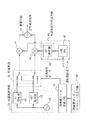
この低い周波数の基底帯域信号を高い周波数の高周波帯域信号に周波数変換する従来の周波数変換装置の一例を図5に示す。図5は、従来の周波数変換装置の一例のブロック回路図である。図5において、基底帯域信号生成手段としての2相ダイレクトデジタルシンセサイザ10から同一周波数で互いに90度の位相差を有する2つの基底帯域信号が出力される。この2相ダイレクトデジタルシンセサイザ10には、周波数データ生成手段11から出力される周波数データが与えられ、これに応じて出力周波数が設定される。この周波数データ生成手段11は、周波数ホッピングパターン発生手段12から出力されるホッピングパターンコードに基づき対応する周波数データを生成して順次出力するように構成されている。そして、2相ダイレクトデジタルシンセサイザ10の2つの基底帯域信号が、1つづつ第1の平衡変調手段14と第2の平衡変調手段16にそれぞれ与えられる。また、高周波発振器18から出力される高周波信号が2つに分岐され、その一方がそのまま第1の平衡変調手段14に与えられ、他方が90度移相器20で90度だけその位相が移動されて第2の平衡変調手段16に与えられる。ここで、高周波発振器18と90度移相器20により、同一周波数で互いに90度の位相差を有する2つの局部発振周波数信号を出力する局部発振手段22が形成されている。そして、第1の平衡変調手段14と第2の平衡変調手段16の出力が、演算手段としての加算手段24により加算されて、高周波帯域信号が出力される。
【0003】
かかる構成の周波数変換装置の動作につき説明する。まず、2相ダイレクトデジタルシンセサイザ10の2つの90度の位相差を有する基底帯域信号を
a・sinωtとa・cosωtとし、
2つの90度の位相差を有する局部発振周波数信号を
b・cosωctとb・sinωctとすれば、
第1の平衡変調手段14の出力は、
ab・sinωt・cosωctであり、
第2の平衡変調手段16の出力は、
ab・cosωt・sinωctである。
そして、これらの第1の平衡変調手段14と第2の平衡変調手段16の出力を加算すれば、その演算出力は、
ab・sin(ωc+ω)tとなる。
したがって、基底帯域信号が局部発振周波数信号の周波数だけ高い高周波帯域信号に周波数変換される。
【0004】
ところで、基底帯域信号はその周波数がホッピングパターンコードに応じて順次に切り換えられるが、2相ダイレクトデジタルシンセサイザ10は高速で切り換えてもその周波数は比較的に安定したものである。また、局部発振周波数信号はその周波数は切り換えられずに一定であって安定している。そこで、図5に示す周波数変換装置を用いることで、周波数の切換を高速でできしかも安定した高周波帯域信号が得られる。
【0005】
【発明が解決しようとする課題】
図5に示す従来の周波数変換装置は、上述のごとく、基底帯域信号を局部発振周波数信号の周波数だけ高い高周波帯域信号に周波数変換するものにすぎない。そこで、図6に示すごとく、基底帯域信号の周波数が切換設定され得る帯域幅がwであれば、周波数変換された高周波帯域信号の帯域幅もwである。このために、2相ダイレクトデジタルシンセサイザ10の帯域幅w以上に広い帯域幅の高周波帯域信号を得ることはできない。
【0006】
ところで、2相ダイレクトデジタルシンセサイザ10は、サンプリング周波数および演算速度などに制約されるために、任意に高い周波数の信号を出力することができない。そこで、出力周波数が切換設定できる帯域幅を充分に拡大することができない。一方、近年の周波数ホッピングスペクトラム拡散通信方式にあっては、出力周波数の帯域幅がより広くかつ高速で安定して切り換えることができる高い周波数の出力信号が必要とされている。このために、図5に示す従来の周波数変換装置では、高速で安定して切り換えられるが、その出力周波数の帯域幅が充分に得られず、近年の周波数ホッピングスペクトラム拡散通信方式には用いることができないものであった。
【0007】
本発明は、上述のごとき従来技術の事情に鑑みてなされたもので、周波数信号の帯域幅の2倍の帯域幅で出力帯域信号を得ることができるようにした周波数シンセサイザ装置を提供することを目的とする。
【0008】
【課題を解決するための手段】
かかる目的を達成するために、本発明の周波数シンセサイザ装置は、周波数データに応じて設定される周波数で互いに90度の位相差を有する2つの周波数信号を出力する周波数信号生成手段と、第1と第2の平衡変調手段と、前記周波数データに応じて切り換えて前記2つの周波数信号を1つづつ前記第1と第2の平衡変調手段にそれぞれ与える切換手段と、互いに90度の位相差を有する2つの局部発振周波数信号を出力して1つづつ前記第1と第2の平衡変調手段に与える局部発振手段と、前記第1と第2の平衡変調手段の出力を加算または減算して出力帯域信号を出力する演算手段と、を備えて構成されている。
【0009】
また、周波数データに応じて設定される周波数で互いに90度の位相差を有する2つの周波数信号を出力する周波数信号生成手段と、前記2つの周波数信号が1つづつ与えられる第1と第2の平衡変調手段と、互いに90度の位相差を有する2つの局部発振周波数信号を出力する局部発振手段と、前記周波数データに応じて切り換えて前記2つの局部発振周波数信号を1つづつ前記第1と第2の平衡変調手段にそれぞれ与える切換手段と、前記第1と第2の平衡変調手段の出力を加算または減算して出力帯域信号を出力する演算手段と、を備えて構成することもできる。
【0010】
また、周波数データに応じて設定される周波数で互いに90度の位相差を有する2つの周波数信号を出力する周波数信号生成手段と、前記2つの周波数信号が1つづつそれぞれ与えられる第1と第2の平衡変調手段と、互いに90度の位相差を有する2つの局部発振周波数信号を出力して1つづつ前記第1と第2の平衡変調手段に与える局部発振手段と、前記周波数データに応じて加算と減算を切り換えて前記第1と第2の平衡変調手段の出力を演算して出力帯域信号を出力する演算切換手段と、を備えて構成しても良い。
【0011】
そして、前記周波数データが与えられる周波数データ変換手段を備え、この周波数データ変換手段により、前記周波数データに応じた周波数設定データを前記周波数信号生成手段に与えるとともに切換制御データを前記切換手段に与えるように構成することもできる。
【0012】
そして、前記周波数データが与えられる周波数データ変換手段を備え、この周波数データ変換手段により、前記周波数データに応じた周波数設定データを前記周波数信号生成手段に与えるとともに演算切換制御データを前記演算切換手段に与えるように構成することもできる。
【0013】
また、前記周波数データは周波数設定データと切換制御データとからなり、前記周波数信号生成手段は前記周波数設定データに応じて前記周波数信号を出力し、前記切換手段は前記切換制御データに応じて接続状態を切換制御するように構成しても良い。
【0014】
また、前記周波数データは周波数設定データと演算切換制御データとからなり、前記周波数信号生成手段は前記周波数設定データに応じた周波数信号を出力し、前記演算切換手段は前記演算切換制御データに応じて演算状態を切換制御するように構成しても良い。
【0015】
そして、ホッピングパターンコードを順次発生する周波数ホッピングパターン発生手段を備え、前記周波数データが前記ホッピングパターンコードに基づいて生成されても良い。
【0016】
そして、前記周波数信号生成手段を2相ダイレクトデジタルシンセサイザを備えて構成しても良い。
【0017】
【発明の実施の形態】
以下、本発明の第1実施例を図1および図2を参照して説明する。図1は、本発明の周波数シンセサイザ装置の第1実施例のブロック回路図である。図2は、第1実施例において出力帯域信号の帯域幅が周波数信号の帯域幅の2倍得られることを説明する図である。図1において、図5と同一部材には同じ符号を付けて重複する説明を省略する。
【0018】
図1において、図5と相違する点は、2相ダイレクトデジタルシンセサイザ10から出力される互いに90度の位相差を有する2つの周波数信号が、切換手段30を介して1つづつ第1の平衡変調手段14と第2の平衡変調手段16にそれぞれ与えられることと、周波数データ生成手段33から出力される周波数データが周波数データ変換手段34に与えられ、この周波数データ変換手段34から周波数データに応じた周波数設定データが2相ダイレクトデジタルシンセサイザ10に与えられるとともに、周波数データに応じた切換制御データが切換手段30に与えられることにある。そして、周波数設定データにより2相ダイレクトデジタルシンセサイザ10は出力周波数が切り換えられ、また切換制御データにより切換手段30の接続状態が切換制御されて、2つの周波数信号が第1の平衡変調手段14と第2の平衡変調手段16にそれぞれ与えられる。この周波数データ生成手段33は、周波数ホッピングパターン発生手段32から出力されるホッピングパターンコードに基づいて周波数データを生成して出力するように構成されている。より具体的にその一例を説明するならば、周波数データ生成手段33における図示しない適宜なメモリにホッピングさせる周波数のデータが予め記憶されており、ホッピングパターンコードに基づいて対応する周波数データを読み出して順次出力するように構成されている。なお、周波数データ生成手段33は、ホッピングパターンコードに基づき対応する周波数データを生成して順次出力できるならば、その構成はいかなるものであっても良い。
【0019】
ここで、周波数ホッピングパターン発生手段32から出力されるホッピングパターンコードに基づいて生成される周波数データは、2相ダイレクトデジタルシンセサイザ10で出力できる帯域幅よりも広い帯域幅で周波数信号を設定するように構成されている。そこで、周波数データ変換手段34は、図示しない適宜なメモリに予め記憶されたデータテーブルなどを参照して、与えられた周波数データに対応させて、2相ダイレクトデジタルシンセサイザ10の帯域幅内にある周波数信号を設定するための周波数設定データと、後述するごとく帯域幅を拡大するために切換手段30の接続状態を切換制御するための切換制御データとを演算出力する。
【0020】
かかる構成において、切換手段30の一方の接続状態により第1の平衡変調手段14には、
a・sinωtとb・cosωctが与えられ、
第2の平衡変調手段16には、
a・cosωtとb・sinωctが与えられ、かかる制御状態では、加算手段24からは、
ab・sin(ωc+ω)tの出力帯域信号が出力される。
また、切換手段30が切り換えられた他方の接続状態により第1の平衡変調手段14には、
a・cosωtとb・cosωctが与えられ、
第2の平衡変調手段16には、
a・sinωtとb・sinωctが与えられ、かかる制御状態では、加算手段24からは、
ab・cos(ωc−ω)tの出力帯域信号が出力される。
この結果、切換手段30の接続状態を適宜に切換制御することで、図2に示すごとく、周波数変換された出力帯域信号は、局部発振周波数信号を中心として、周波数信号の帯域幅wのアッパーサイドバンドとロウアーサイドバンドがともに得られる。そこで、出力帯域信号の帯域幅を周波数信号の帯域幅wの2倍に拡大することができる。しかも、2相ダイレクトデジタルシンセサイザ10と切換手段30を、ホッピングパターンコードに応じて高速で切り換えるならば、広い帯域幅でしかも高速切換で周波数ホッピングさせることができ、周波数ホッピングスペクトラム拡散通信方式に好適である。
【0021】
なお、2相ダイレクトデジタルシンセサイザ10は、出力帯域信号に対して相対的に低い周波数の周波数信号を出力すれば良く、零Hzを含む帯域幅の基底帯域信号であっても、零Hzを含まない帯域幅の信号であっても良く、特定の周波数に限定されるものでない。また、出力帯域信号も、2相ダイレクトデジタルシンセサイザ10の周波数信号に対して相対的に高い周波数であれば良く、特定の高周波数などに特定されるものでない。さらに、局部発振手段22の高周波発振器18も、実用的に高い周波数が用いられているのでかかる名称としたに過ぎず、局部発振手段22から出力される局部発振信号の周波数は、その用途に応じて適宜に設定されれば良い。そして、2相ダイレクトデジタルシンセサイザ10の周波数信号が零Hzを含む帯域幅であるならば、出力帯域信号は局部発振周波数信号を中心としてアッパーサイドバンドとロウアーサイドバンドが連続する周波数信号の帯域幅wの2倍の帯域幅が得られる。また、周波数信号が零Hzを含まない帯域幅であるならば、出力帯域信号は局部発振周波数信号を中心としてアッパーサイドバンドとロウアーサイドバンドが対称に分離し、それぞれに周波数信号の帯域幅wと同じ帯域幅が得られ、アッパーサイドバンドとロウアーサイドバンドの各帯域幅の合計が、周波数信号の帯域幅wの2倍となる。
【0022】
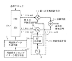
次に、本発明の第2実施例を図3を参照して説明する。図3は、本発明の周波数シンセサイザ装置の第2実施例のブロック回路図である。図3において、1相ダイレクトデジタルシンセサイザ40から出力される比較的に低い周波数の周波数信号が2つに分岐され、一方がそのまま第1の平衡変調手段14に与えられ、他方が90度移相器42で90度だけその位相が移動されて第2の平衡変調手段16に与えられる。ここで、1相ダイレクトデジタルシンセサイザ40と90度移相器42により、同一周波数で互いに90度の位相差を有する2つの周波数信号を出力する周波数信号生成手段44が形成される。そして、1相ダイレクトデジタルシンセサイザ40は、周波数データ生成手段45から出力される周波数データとしての周波数設定データにより出力周波数が切換設定される。この周波数データは、周波数設定データと後述する切換制御データとからなる。また、高周波発振器48から出力される高い周波数の信号が2つに分岐されて、一方が+45度移相器50で45度だけその位相が進められ、他方が−45度移相器52で45度だけその位相が遅らされる。そこで、+45度移相器50と−45度移相器52からは、同じ周波数で互いに90度の位相差を有する2つの局部発振周波数信号が出力される。なお、高周波発振器48と+45度移相器50と−45度移相器52で局部発振手段54が形成されている。さらに、局部発振手段54の2つの局部発振周波数信号が切換手段56を介して1つづつ第1の平衡変調手段14と第2の平衡変調手段16にそれぞれ与えられる。この切換手段56は、周波数データ生成手段45から出力される周波数データとしての切換制御データにより切換制御される。そして、第1の平衡変調手段14と第2の平衡変調手段16の出力が、演算手段としての減算手段58により減算されて出力帯域信号が出力される。
【0023】
ここで、第2実施例では、周波数データ生成手段45からは、周波数データとしての周波数設定データと切換制御データが直接出力され、1相ダイレクトデジタルシンセサイザ40と切換手段56に与えられている。第2実施例にあっては、周波数ホッピングパターン発生手段46から出力されるホッピングパターンコードに基づいて、周波数データ生成手段45は直接的に周波数設定データおよび切換制御データを生成するように構成されている。より具体的にその一例を説明するならば、周波数データ生成手段45における図示しない適宜なメモリにホッピングさせる周波数に対応する周波数設定データおよび切換制御データが予め記憶されており、ホッピングパターンコードに基づき対応する周波数設定データおよび切換制御データを読み出して順次出力するように構成されている。なお、第2実施例における周波数データ生成手段45は、ホッピングパターンコードに基づき対応する周波数データとしての周波数設定データおよび切換制御データを直接的に生成して順次出力できるならば、その構成はいかなるものであっても良い。
【0024】
かかる構成の第2実施例の周波数シンセサイザ装置にあっても、図1に示す第1実施例と同様に、周波数変換された出力帯域信号は、局部発振周波数信号を中心として周波数信号の帯域幅wのアッパーサイドバンドとロウアーサイドバンドが出力され、帯域幅が2倍に拡大される。また、周波数データ生成手段45から出力される周波数データとしての周波数設定データおよび切換制御データによって、1相ダイレクトデジタルシンセサイザ40と切換手段56が直接的に制御されるので、第1実施例に比べて周波数データ変換手段34による演算処理を必要としない分だけ迅速な制御が可能であり、高速での周波数ホッピングにより好適である。
【0025】
さらに、本発明の第3実施例を図4を参照して説明する。図4は、本発明の周波数シンセサイザ装置の第3実施例のブロック回路図である。図4において、PLL回路などを用いた低周波発振器60から出力される低い周波数の周波数信号が2つに分岐され、一方が+45度移相器62で45度だけその位相が進められて第1の平衡変調手段14に与えられ、他方が−45度移相器64で45度だけその位相が遅らされて第2の平衡変調手段16に与えられる。そして、低周波発振器60と+45度移相器62と−45度移相器64で周波数信号生成手段66が形成され、+45度移相器62と−45度移相器64からは、同じ周波数で90度の位相差を有する2つの周波数信号が出力される。ここで、低周波発振器60は、中央演算手段68から出力される周波数データとしての周波数設定データにより発振周波数が切換設定される。また、高周波発振器18と90度移相器20からなる局部発振手段22から出力される互いに90度の位相差を有する2つの局部発振周波数信号が、1つづつ第1の平衡変調手段14と第2の平衡変調手段16に与えられる。そして、第1の平衡変調手段14と第2の平衡変調手段16の出力が、加算と減算を切り換えて演算する演算切換手段70に与えられて、出力帯域信号が出力される。この演算切換手段70は、中央演算手段68から出力される周波数データとしての演算切換制御データにより加算と減算の演算状態が切り換えられる。
【0026】
なお、演算切換手段70は、演算作用が加算と減算に切り換えられるものに限られず、加算手段と減算手段とが選択手段により適宜に選択されるように構成されたものであっても良い。また、低周波発振器60は、その発振周波数が切換制御できれば良く、いかなる構成であっても良い。
【0027】
かかる構成の第3実施例の周波数シンセサイザ装置にあっても、第1と第2実施例と同様に、周波数変換された出力帯域信号は、局部発振周波数信号を中心として周波数信号の帯域幅wのアッパーサイドバンドとロウアーサイドバンドが出力され、帯域幅の広いものとなる。
【0028】
なお、上記実施例において、周波数信号生成手段は、互いに90度の位相差を有する2つの周波数信号を出力できれば良く、上記実施例の構造に限られるものでない。また、局部発振手段も、互いに90度の位相差を有する2つの局部発振周波数信号を出力できれば良く、上記実施例の構造に限られたものでない。そして、本発明の周波数シンセサイザ装置は、出力帯域信号を高速で切り換えるものに限られず、周波数信号生成手段が周波数信号の高速切換には適していないものであっても、その目的に応じて使用することができることは勿論である。また、2相ダイレクトデジタルシンセサイザおよび周波数信号生成手段の周波数信号の周波数の切換設定、および切換手段もしくは演算切換手段の切換制御は、周波数ホッピングパターン発生手段のホッピングパターンコードに基づいて行われるものや中央演算手段から出力される周波数データなどにより行われるものに限られず、出力帯域信号を設定するための周波数データに応じて適宜に切換制御されるものであればいかなる構造であっても良い。
【0029】
【発明の効果】
以上の説明から明らかなように、本発明の周波数シンセサイザ装置は構成されているので、以下のごとき格別な効果を奏する。
【0030】
請求項1ないし3記載のいずれの周波数シンセサイザ装置にあっても、周波数変換された出力帯域信号の帯域幅を、周波数信号の帯域幅の2倍に拡大することができる。
【0031】
そして、請求項4または5記載の周波数シンセサイザ装置にあっては、周波数データを周波数データ変換手段で適宜に変換して周波数信号を設定する周波数設定データと切換手段の接続状態を制御する切換制御データまたは演算切換手段の演算状態を制御する演算切換制御データに変換するので、周波数データの制約が少ない。
【0032】
また、請求項6または7記載の周波数シンセサイザ装置にあっては、周波数データとしての周波数設定データと切換制御データまたは演算切換制御データにより、直接的に周波数信号の設定と切換手段の接続状態または演算切換手段の演算状態の制御がなされるので、演算処理する必要がないぶんだけ、出力帯域信号の高速切換が可能である。
【0033】
そして、請求項8記載の周波数シンセサイザ装置にあっては、周波数ホッピングパターン発生手段のホッピングパターンコードに基づいて生成される周波数データにより周波数信号の周波数を切換設定するとともに、切換手段もしくは演算切換手段を適宜に切り換えるので、出力帯域信号の周波数の切換を簡単に行うことができる。
【0034】
そして、請求項9記載の周波数シンセサイザ装置にあっては、周波数信号生成手段に2相ダイレクトデジタルシンセサイザを備えるので、周波数信号の周波数を高速で切り換えるのに好適である。特に、周波数ホッピングパターン発生手段のホッピングパターンコードに基づいて生成されるを周波数データにより、周波数信号生成手段としての2相ダイレクトデジタルシンセサイザから出力される周波数信号を高速で切り換えるならば、ホッピングパターンコードに応じて出力帯域信号の周波数が高速で切り換えられるとともにその帯域幅が拡大されているので、周波数ホッピングスペクトラム拡散通信方式に用いて好適である。
【図面の簡単な説明】
【図1】本発明の周波数シンセサイザ装置の第1実施例のブロック回路図である。
【図2】本発明の周波数シンセサイザ装置の第1実施例において、出力帯域信号の帯域幅が周波数信号の帯域幅の2倍得られることを説明する図である。
【図3】本発明の周波数シンセサイザ装置の第2実施例のブロック回路図である。
【図4】本発明の周波数シンセサイザ装置の第3実施例のブロック回路図である。
【図5】従来の周波数変換装置の一例のブロック回路図である。
【図6】従来の周波数変換装置の一例において、高周波帯域信号の帯域幅が基底帯域信号の帯域幅と同じであることを説明する図である。
【符号の説明】
10 2相ダイレクトデジタルシンセサイザ
11、33、45 周波数データ生成手段
12、32、46 周波数ホッピングパターン発生手段
14 第1の平衡変調手段
16 第2の平衡変調手段
22、54 局部発振手段
24 加算手段
30、56 切換手段
34 周波数データ変換手段
44、66 周波数信号生成手段
58 減算手段
68 中央演算手段
70 演算切換手段[0001]
BACKGROUND OF THE INVENTION
The present invention can frequency-convert a relatively low frequency signal to a higher frequency output band signal and expand its bandwidth, and is suitable for switching an output band signal of the expanded bandwidth at high speed. The present invention relates to a frequency synthesizer device, and more particularly to a frequency synthesizer device suitable for use in a frequency hopping spread spectrum communication system.
[0002]
[Prior art]
The frequency hopping spread spectrum communication system requires a frequency synthesizer device that can switch the frequency at high speed according to various hopping patterns. 2. Description of the Related Art Conventionally, a device using a phase locked loop (PLL) synthesizer has been widely used as a device for switching frequencies. However, in this PLL system, the response of the loop filter is slow, and it is difficult to obtain a sufficiently fast switching time. Therefore, it has been proposed to use a direct digital synthesizer (DDS) capable of switching the frequency at high speed, but this direct digital synthesizer can output only a relatively low frequency, and a higher frequency is required. Needed to obtain a desired frequency by converting the output frequency of the direct digital synthesizer to a higher frequency.
FIG. 5 shows an example of a conventional frequency converter that converts the frequency of the low-frequency baseband signal into a high-frequency high-frequency signal. FIG. 5 is a block circuit diagram of an example of a conventional frequency conversion device. In FIG. 5, two baseband signals having a phase difference of 90 degrees from each other at the same frequency are output from the two-phase direct
[0003]
The operation of the frequency converter having such a configuration will be described. First, the baseband signals having two 90-degree phase differences of the two-phase direct
If two local oscillation frequency signals having a phase difference of 90 degrees are b · cos ωct and b · sin ωct,
The output of the first balanced modulation means 14 is
ab · sinωt · cosωct,
The output of the second balanced modulation means 16 is
ab · cos ωt · sin ωct.
If the outputs of the first balanced modulation means 14 and the second balanced modulation means 16 are added, the calculation output is
ab · sin (ωc + ω) t.
Therefore, the baseband signal is frequency-converted into a high-frequency band signal that is higher by the frequency of the local oscillation frequency signal.
[0004]
By the way, the frequency of the baseband signal is sequentially switched in accordance with the hopping pattern code, but the frequency of the two-phase direct
[0005]
[Problems to be solved by the invention]
As described above, the conventional frequency conversion device shown in FIG. 5 merely converts the baseband signal into a high-frequency band signal that is higher by the frequency of the local oscillation frequency signal. Therefore, as shown in FIG. 6, if the bandwidth in which the frequency of the baseband signal can be switched and set is w, the bandwidth of the frequency-converted high-frequency band signal is also w. For this reason, it is not possible to obtain a high-frequency band signal having a bandwidth wider than the bandwidth w of the two-phase direct
[0006]
By the way, since the two-phase direct
[0007]
The present invention has been made in view of the circumstances of the prior art as described above, and provides a frequency synthesizer device capable of obtaining an output band signal with a bandwidth twice that of the frequency signal. Objective.
[0008]
[Means for Solving the Problems]
In order to achieve such an object, a frequency synthesizer device according to the present invention includes a frequency signal generating unit that outputs two frequency signals having a phase difference of 90 degrees with each other at a frequency set according to frequency data, A second balanced modulation unit, a switching unit that switches according to the frequency data and supplies the two frequency signals one by one to the first and second balanced modulation units, respectively, and has a phase difference of 90 degrees from each other. An output band obtained by adding or subtracting the outputs of the local oscillation means for outputting the two local oscillation frequency signals to the first and second balanced modulation means one by one and the outputs of the first and second balanced modulation means one by one And an arithmetic means for outputting a signal.
[0009]
Further, frequency signal generating means for outputting two frequency signals having a phase difference of 90 degrees with each other at a frequency set according to the frequency data, and first and second frequency signals are provided one by one. Balanced modulation means, local oscillation means for outputting two local oscillation frequency signals having a phase difference of 90 degrees from each other, and switching between the two local oscillation frequency signals according to the frequency data, the first and second local oscillation frequency signals one by one It is also possible to comprise a switching means for supplying to each of the second balanced modulation means, and an arithmetic means for adding or subtracting the outputs of the first and second balanced modulation means to output an output band signal.
[0010]
Further, a frequency signal generating means for outputting two frequency signals having a phase difference of 90 degrees with each other at a frequency set according to the frequency data, and a first and a second that are provided with the two frequency signals one by one, respectively. Balanced oscillation means, local oscillation means for outputting two local oscillation frequency signals having a phase difference of 90 degrees to each other and supplying them to the first and second balanced modulation means one by one, and depending on the frequency data An arithmetic switching means for switching the addition and subtraction to calculate the outputs of the first and second balanced modulation means and output an output band signal may be provided.
[0011]
The frequency data conversion means is provided with the frequency data, and the frequency data conversion means provides the frequency setting data corresponding to the frequency data to the frequency signal generation means and the switching control data to the switching means. It can also be configured.
[0012]
The frequency data conversion means is provided with the frequency data, and the frequency data conversion means supplies the frequency setting data corresponding to the frequency data to the frequency signal generation means and the operation switching control data to the operation switching means. It can also be configured to give.
[0013]
The frequency data includes frequency setting data and switching control data, the frequency signal generating means outputs the frequency signal according to the frequency setting data, and the switching means is connected according to the switching control data. It may be configured to control switching.
[0014]
The frequency data includes frequency setting data and calculation switching control data, the frequency signal generation means outputs a frequency signal corresponding to the frequency setting data, and the calculation switching means responds to the calculation switching control data. You may comprise so that a calculation state may be switched.
[0015]
In addition, a frequency hopping pattern generation unit that sequentially generates hopping pattern codes may be provided, and the frequency data may be generated based on the hopping pattern codes.
[0016]
The frequency signal generation means may be configured to include a two-phase direct digital synthesizer.
[0017]
DETAILED DESCRIPTION OF THE INVENTION
Hereinafter, a first embodiment of the present invention will be described with reference to FIGS. FIG. 1 is a block circuit diagram of a first embodiment of the frequency synthesizer device of the present invention. FIG. 2 is a diagram for explaining that the bandwidth of the output band signal can be obtained twice that of the frequency signal in the first embodiment. In FIG. 1, the same members as those in FIG.
[0018]
In FIG. 1, the difference from FIG. 5 is that two frequency signals having a phase difference of 90 degrees outputted from the two-phase direct
[0019]
Here, the frequency data generated based on the hopping pattern code output from the frequency hopping pattern generation means 32 is set so that the frequency signal has a wider bandwidth than the bandwidth that can be output by the two-phase direct
[0020]
In such a configuration, depending on one connection state of the switching means 30, the first balanced modulation means 14 includes
a · sinωt and b · cosωct are given,
The second balanced modulation means 16 includes
a · cos ωt and b · sin ωct are given, and in this control state, the adding means 24
An output band signal of ab · sin (ωc + ω) t is output.
Further, the first balanced modulation means 14 is connected to the other connection state in which the switching means 30 is switched.
a · cos ωt and b · cos ωct are given,
The second balanced modulation means 16 includes
a · sin ωt and b · sin ωct are given, and in this control state, the adding means 24
An output band signal of ab · cos (ωc−ω) t is output.
As a result, by appropriately switching the connection state of the switching means 30, as shown in FIG. 2, the frequency-converted output band signal is centered on the local oscillation frequency signal and the upper side of the frequency signal bandwidth w. Band and lower side band can be obtained together. Therefore, the bandwidth of the output band signal can be expanded to twice the bandwidth w of the frequency signal. Moreover, if the two-phase direct
[0021]
The two-phase direct
[0022]
Next, a second embodiment of the present invention will be described with reference to FIG. FIG. 3 is a block circuit diagram of a second embodiment of the frequency synthesizer device of the present invention. In FIG. 3, a relatively low frequency signal output from the one-phase direct
[0023]
Here, in the second embodiment, frequency setting data and switching control data as frequency data are directly output from the frequency data generating means 45 and provided to the one-phase direct
[0024]
Even in the frequency synthesizer device of the second embodiment having such a configuration, as in the first embodiment shown in FIG. 1, the frequency-converted output band signal has a frequency signal bandwidth w centered on the local oscillation frequency signal. The upper sideband and lower sideband are output and the bandwidth is doubled. Further, since the one-phase direct
[0025]
Furthermore, a third embodiment of the present invention will be described with reference to FIG. FIG. 4 is a block circuit diagram of a third embodiment of the frequency synthesizer device of the present invention. In FIG. 4, a low frequency signal output from a
[0026]
Note that the operation switching means 70 is not limited to the one whose operation is switched between addition and subtraction, and may be configured such that the addition means and the subtraction means are appropriately selected by the selection means. Further, the
[0027]
Even in the frequency synthesizer device of the third embodiment having such a configuration, as in the first and second embodiments, the frequency-converted output band signal has a frequency signal bandwidth w centered on the local oscillation frequency signal. The upper sideband and lower sideband are output, and the bandwidth is wide.
[0028]
In the above-described embodiment, the frequency signal generation unit only needs to output two frequency signals having a phase difference of 90 degrees from each other, and is not limited to the structure of the above-described embodiment. The local oscillating means is not limited to the structure of the above embodiment as long as it can output two local oscillation frequency signals having a phase difference of 90 degrees. The frequency synthesizer device of the present invention is not limited to one that switches the output band signal at high speed, and even if the frequency signal generation means is not suitable for high-speed switching of the frequency signal, it is used according to its purpose. Of course you can. The frequency switching setting of the frequency signal of the two-phase direct digital synthesizer and the frequency signal generating means, and the switching control of the switching means or the arithmetic switching means are performed based on the hopping pattern code of the frequency hopping pattern generating means, The structure is not limited to that performed by the frequency data output from the calculation means, and any structure may be used as long as the switching is appropriately performed according to the frequency data for setting the output band signal.
[0029]
【The invention's effect】
As is apparent from the above description, since the frequency synthesizer device of the present invention is configured, the following special effects are achieved.
[0030]
In any of the frequency synthesizer devices according to
[0031]
In the frequency synthesizer device according to claim 4 or 5, the frequency setting data for setting the frequency signal by appropriately converting the frequency data by the frequency data converting means and the switching control data for controlling the connection state of the switching means. Alternatively, since it is converted into calculation switching control data for controlling the calculation state of the calculation switching means, there are few restrictions on the frequency data.
[0032]
Further, in the frequency synthesizer device according to claim 6 or 7, the frequency signal setting and the connection state or calculation of the switching means are directly performed by frequency setting data as frequency data and switching control data or calculation switching control data. Since the calculation state of the switching means is controlled, the output band signal can be switched at high speed to the extent that there is no need to perform calculation processing.
[0033]
In the frequency synthesizer device according to claim 8, the frequency signal frequency is switched and set by the frequency data generated based on the hopping pattern code of the frequency hopping pattern generating means, and the switching means or the arithmetic switching means is provided. Since switching is performed as appropriate, the frequency of the output band signal can be easily switched.
[0034]
In the frequency synthesizer device according to the ninth aspect, since the frequency signal generating means includes the two-phase direct digital synthesizer, it is suitable for switching the frequency of the frequency signal at high speed. In particular, if the frequency data generated based on the hopping pattern code of the frequency hopping pattern generation means is switched at high speed by the frequency data, the frequency signal output from the two-phase direct digital synthesizer as the frequency signal generation means is changed to the hopping pattern code. Accordingly, the frequency of the output band signal is switched at a high speed and the bandwidth is widened, which is suitable for the frequency hopping spread spectrum communication system.
[Brief description of the drawings]
FIG. 1 is a block circuit diagram of a first embodiment of a frequency synthesizer device of the present invention.
FIG. 2 is a diagram for explaining that in the first embodiment of the frequency synthesizer device of the present invention, the bandwidth of the output band signal can be obtained twice the bandwidth of the frequency signal.
FIG. 3 is a block circuit diagram of a second embodiment of the frequency synthesizer device of the present invention.
FIG. 4 is a block circuit diagram of a third embodiment of the frequency synthesizer device of the present invention.
FIG. 5 is a block circuit diagram of an example of a conventional frequency conversion device.
FIG. 6 is a diagram for explaining that the bandwidth of a high-frequency band signal is the same as the bandwidth of a baseband signal in an example of a conventional frequency conversion device.
[Explanation of symbols]
10 2-phase direct
Claims (9)
Priority Applications (1)
| Application Number | Priority Date | Filing Date | Title |
|---|---|---|---|
| JP6054998A JP3608765B2 (en) | 1998-02-25 | 1998-02-25 | Frequency synthesizer device |
Applications Claiming Priority (1)
| Application Number | Priority Date | Filing Date | Title |
|---|---|---|---|
| JP6054998A JP3608765B2 (en) | 1998-02-25 | 1998-02-25 | Frequency synthesizer device |
Publications (2)
| Publication Number | Publication Date |
|---|---|
| JPH11243351A JPH11243351A (en) | 1999-09-07 |
| JP3608765B2 true JP3608765B2 (en) | 2005-01-12 |
Family
ID=13145492
Family Applications (1)
| Application Number | Title | Priority Date | Filing Date |
|---|---|---|---|
| JP6054998A Expired - Lifetime JP3608765B2 (en) | 1998-02-25 | 1998-02-25 | Frequency synthesizer device |
Country Status (1)
| Country | Link |
|---|---|
| JP (1) | JP3608765B2 (en) |
Cited By (1)
| Publication number | Priority date | Publication date | Assignee | Title |
|---|---|---|---|---|
| CN101060343B (en) * | 2006-04-21 | 2011-01-26 | 瑞萨电子株式会社 | IC for frequency hopping communication |
Families Citing this family (5)
| Publication number | Priority date | Publication date | Assignee | Title |
|---|---|---|---|---|
| JP4521959B2 (en) * | 2000-10-06 | 2010-08-11 | パナソニック株式会社 | Mixer circuit |
| KR100646314B1 (en) | 2005-12-16 | 2006-11-23 | 삼성전자주식회사 | Multi-input multi-frequency synthesizing apparatus and method for multi-band rf receiver |
| JP2009159604A (en) * | 2007-12-03 | 2009-07-16 | Mitsubishi Electric Corp | Signal generating device, transmitter and transmitter-receiver |
| EP2432075B1 (en) * | 2009-05-14 | 2018-11-14 | Nec Corporation | Phase shifter, wireless communication apparatus, and phase shift control method |
| JP5424816B2 (en) * | 2009-10-29 | 2014-02-26 | 三菱電機株式会社 | Frequency synthesizer |
-
1998
- 1998-02-25 JP JP6054998A patent/JP3608765B2/en not_active Expired - Lifetime
Cited By (1)
| Publication number | Priority date | Publication date | Assignee | Title |
|---|---|---|---|---|
| CN101060343B (en) * | 2006-04-21 | 2011-01-26 | 瑞萨电子株式会社 | IC for frequency hopping communication |
Also Published As
| Publication number | Publication date |
|---|---|
| JPH11243351A (en) | 1999-09-07 |
Similar Documents
| Publication | Publication Date | Title |
|---|---|---|
| KR100539929B1 (en) | Digital frequency modulator | |
| KR960012737A (en) | Phase Locked Circuit (PLL) System Clock Generators that Instantly Shift Clock Frequency | |
| JP2806059B2 (en) | Phase locked loop synthesizer | |
| JP3608765B2 (en) | Frequency synthesizer device | |
| WO2007025355A1 (en) | Reconfigurable signal modulator | |
| JPH0715371A (en) | Superheterodyne system transmission/reception method and transmitter/receiver | |
| KR930009228A (en) | Right angle modulation circuit | |
| JPH07264063A (en) | Frequency synthesizer | |
| US5847622A (en) | Quadrature phase shift keying modulating apparatus | |
| US8014422B2 (en) | Method and system for utilizing a single PLL to clock an array of DDFS for multi-protocol applications | |
| JP3999640B2 (en) | Frequency control device | |
| JP2919328B2 (en) | Modulation circuit | |
| JPH10304000A (en) | Quadrature amplitude modulating device | |
| JP2002158725A (en) | Dual mode modulator | |
| JP3712141B2 (en) | Phase-locked loop device | |
| JP2552948B2 (en) | Modulator | |
| US6625422B1 (en) | Signal generator | |
| JP3067945B2 (en) | Modulating device and wireless device provided with the modulating device | |
| JP3105381B2 (en) | QPSK modulator and QPSK demodulator | |
| JP2000004121A (en) | Oscillation modulating circuit | |
| JPS59153333A (en) | Phase and frequency variable oscillator | |
| KR100277129B1 (en) | Dual Mode Baseband Analog Devices of Code Division Multiple Processing Mobile Communication Terminals | |
| KR100401196B1 (en) | Method and apparatus for bypass i/q mixer in frequency modulation mode of dual cdma mobile communication equipment | |
| JPH08237310A (en) | Signal generator | |
| KR100345308B1 (en) | Dual band frequency generator using mixer |
Legal Events
| Date | Code | Title | Description |
|---|---|---|---|
| A977 | Report on retrieval |
Free format text: JAPANESE INTERMEDIATE CODE: A971007 Effective date: 20040831 |
|
| TRDD | Decision of grant or rejection written | ||
| A01 | Written decision to grant a patent or to grant a registration (utility model) |
Free format text: JAPANESE INTERMEDIATE CODE: A01 Effective date: 20041005 |
|
| A61 | First payment of annual fees (during grant procedure) |
Free format text: JAPANESE INTERMEDIATE CODE: A61 Effective date: 20041008 |
|
| R150 | Certificate of patent or registration of utility model |
Free format text: JAPANESE INTERMEDIATE CODE: R150 |
|
| R250 | Receipt of annual fees |
Free format text: JAPANESE INTERMEDIATE CODE: R250 |
|
| FPAY | Renewal fee payment (event date is renewal date of database) |
Free format text: PAYMENT UNTIL: 20081022 Year of fee payment: 4 |
|
| FPAY | Renewal fee payment (event date is renewal date of database) |
Free format text: PAYMENT UNTIL: 20091022 Year of fee payment: 5 |
|
| FPAY | Renewal fee payment (event date is renewal date of database) |
Free format text: PAYMENT UNTIL: 20101022 Year of fee payment: 6 |
|
| FPAY | Renewal fee payment (event date is renewal date of database) |
Free format text: PAYMENT UNTIL: 20101022 Year of fee payment: 6 |
|
| FPAY | Renewal fee payment (event date is renewal date of database) |
Free format text: PAYMENT UNTIL: 20111022 Year of fee payment: 7 |
|
| FPAY | Renewal fee payment (event date is renewal date of database) |
Free format text: PAYMENT UNTIL: 20111022 Year of fee payment: 7 |
|
| FPAY | Renewal fee payment (event date is renewal date of database) |
Free format text: PAYMENT UNTIL: 20111022 Year of fee payment: 7 |
|
| FPAY | Renewal fee payment (event date is renewal date of database) |
Free format text: PAYMENT UNTIL: 20121022 Year of fee payment: 8 |
|
| FPAY | Renewal fee payment (event date is renewal date of database) |
Free format text: PAYMENT UNTIL: 20121022 Year of fee payment: 8 |
|
| FPAY | Renewal fee payment (event date is renewal date of database) |
Free format text: PAYMENT UNTIL: 20121022 Year of fee payment: 8 |
|
| FPAY | Renewal fee payment (event date is renewal date of database) |
Free format text: PAYMENT UNTIL: 20121022 Year of fee payment: 8 |
|
| FPAY | Renewal fee payment (event date is renewal date of database) |
Free format text: PAYMENT UNTIL: 20131022 Year of fee payment: 9 |
|
| R250 | Receipt of annual fees |
Free format text: JAPANESE INTERMEDIATE CODE: R250 |
|
| R250 | Receipt of annual fees |
Free format text: JAPANESE INTERMEDIATE CODE: R250 |
|
| R250 | Receipt of annual fees |
Free format text: JAPANESE INTERMEDIATE CODE: R250 |
|
| R250 | Receipt of annual fees |
Free format text: JAPANESE INTERMEDIATE CODE: R250 |
|
| R250 | Receipt of annual fees |
Free format text: JAPANESE INTERMEDIATE CODE: R250 |
|
| EXPY | Cancellation because of completion of term |