【0001】
【発明の属する技術分野】
本発明は、クランクシャフトとコネクティングロッドとの連結部に設けられる軸受部への潤滑油の供給機構に関するものであり、特に、上記軸受部がすべり軸受からなるものにおいて、軸受面における油膜の破断等が生じないようにした潤滑油供給機構に関するものである。
【0002】
【従来の技術】
従来の、クランクシャフトにおけるコネクティングロッドとの連結部における軸受部(すべり軸受)への潤滑油の供給機構は、例えば図4に示す如く、クランクシャフト10の一つの軸部130’から隣りの軸部130のところにかけて斜めに設けられた供給路110を基礎に形成されるようになっているものである。そして、このような供給路110の、その一方の開口部120は、コネクティングロッド20との間に設けられたすべり軸受30の軸受面とすべり接触するところに設けられるようになっているものである。このような構成からなる供給路110等を経由して、潤滑油は、図4の矢印図示の如く、開口部120から、すべり軸受30の軸受面へと供給されるようになっているものである。
【0003】
【発明が解決しようとする課題】
このような構成からなる従来の潤滑油供給機構においては、すべり軸受30とクランクシャフト軸部130との接触面である軸受面へは、上記供給路110の開口部120を介して潤滑油が供給されることとなる。これによって、上記両者の接触面である軸受面には、所定の油膜が形成されることとなる。この油膜を介して、クランクシャフト10の軸部130とすべり軸受30との間には軸受機構が形成されることとなる。ところで、この従来のものにおいては、軸受面の、その幅方向のほぼ中央部のところに、供給路110の開口部120が設けられるようになっている。そして、この開口部120は、すべり軸受30の軸受面に十分な潤滑油を供給するために、比較的大きな開口面積を有するようになっている。そのため、上記クランクシャフト10の軸部130とコネクティングロッド20との間に大きな荷重が加わることとなった場合に、上記すべり軸受30の軸受面のところは、大きな圧力が加わった状態ですべり運動が行なわれることとなり、当該軸受面に形成されている油膜は、上記比較的大きな開口面積を有する開口部120のところで切断(破断)されるおそれがある。このような問題点を解決するために、すべり軸受とすべり接触をする軸受面のところには、潤滑油供給のための開口部等を有しないようにした、すべり軸受への潤滑油供給機構を提供しようとするのが、本発明の目的(課題)である。
【0004】
【課題を解決するための手段】
上記課題を解決するために、本発明においては次のような手段を講ずることとした。すなわち、請求項1記載の発明においては、クランクシャフトとコネクティングロッドとの連結部に設けられる軸受部への潤滑油の供給機構に関して、上記クランクシャフトの軸部の両側面部に形成される肩部の付け根のところに設けられるものであって、上記コネクティングロッドとの間に設けられるすべり軸受の両側端部の全周にわたるように設けられる溝のところに、クランクシャフトの軸内に設けられた潤滑油供給路の開口部を設けるようにした構成を採ることとした。
【0005】
このような構成を採ることにより、本発明のものにおいては次のような作用を呈することとなる。すなわち、コネクティングロッドからの大きな変動荷重を受ける上記すべり軸受の軸受面(摺動面)には、潤滑油供給のための給油孔(開口部)が設けられておらず、軸受面(摺動面)は平滑な面となっているので、クランクシャフトの軸部と上記すべり軸受の軸受面との間における相対的なすべり運動(摺動運動)時において、上記摺動面に形成される油膜は、常に正常な状態に保たれることとなる。従って、従来のものにおける如く、給油孔によって、上記油膜が切断(破断)されると言うような不都合の生ずることが無い。特に、ピストンからの衝撃的な変動荷重を受けるコネクティングロッドとの軸受面においては、給油孔等による不連続部の存在することは油膜の保持に悪い影響を及ぼすこととなる。これらのことからも、本発明のものにおける如く、潤滑油供給のための開口部(給油孔)が軸受面に存在しない構成からなるものにおいては、油膜の保持に優れた能力を発揮することとなる。
【0006】
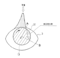
また、本発明のものにおいては、上記潤滑油供給のための開口部(給油孔)が、軸受面のところではなく、すべり軸受の側端部のところに設けられるようになっているものであるところから、その開口面積を大きく採ることができるようになり、潤滑油を十分に軸受部に供給することができるようになる。すなわち、すべり軸受の両側端部のところに形成された空間部を介して、その全周にわたって万遍なく潤滑油を供給することができるようになる。そして、このようにすべり軸受の両側端部のところに供給された潤滑油は、クランクシャフトの軸部とすべり軸受の軸受面との間における相対回転運動中において、例えば図3に示す如く、その円周方向における負圧発生部から、上記軸部とすべり軸受の軸受面との間の隙間内へと吸引(導入)されることとなる。そして、この隙間(軸受面)に供給された潤滑油は、すべり軸受の軸受面の全面にわたって導入されることとなる。その結果、上記軸受面の全面にわたって正常な油膜が形成されることとなる。
【0007】
次に、請求項1記載の第二の発明について説明する。このものも、その基本的な点は、上記第一の発明のものと同じである。その特徴とするところは、上記潤滑油供給路の開口部(給油孔)を、クランクシャフトの軸部のところであって、上記コネクティングロッドとの間に設けられるすべり軸受の両側端部の周りに形成される肩部の、その付け根のところに設けられるR溝のところであって、かつ、クランク半径が最小の値を有するところに設けるようにしたことである。一般に、上記肩部の付け根のところには、軸部の強度向上を図るために、冷間塑性加工手段に基づくローラ加工が施されるようになっているものである。そして、このローラ加工によって、上記肩部の付け根のところには、R溝が形成されるようになっている。このR溝のところに開口部を設けることによって、開口面積の大きな給油孔を形成することができるようになり、十分な潤滑油の供給を行なうことができるようになる。
【0008】
また、このようにして供給された潤滑油は、上記R溝を介して、すべり軸受の側端部に、その全周にわたって万遍なく供給されることとなる。その結果、軸受面へは、十分な潤滑油の供給が行なわれることとなり、軸受面における油膜の形成が確実に行なわれることとなる。また、上記開口部(給油孔)は、クランクシャフトの軸部の肩部の、その付け根のところに設けられるようになっており、クランク半径の最も小さな値を有するところに設けられるようになっているものである。従って、潤滑油に働く遠心力が最も小さな値を有するようになり、供給された潤滑油は遠心力によって飛散させられるようなことがない。その結果、十分に、上記すべり軸受の軸受面への潤滑油の供給が成されることとなる。
【0009】
【発明の実施の形態】
本発明の実施の形態について、図1ないし図3を基に説明する。本発明の実施の形態に関するものの、その構成は、図1に示す如く、クランクシャフト1と、当該クランクシャフト1の軸部(クランクピン)13のところに、相対回転運動が可能なように、かつ、相対すべり運動が可能なように連結されるコネクティングロッド2と、当該コネクティングロッド2と上記クランクシャフト1の軸部(クランクピン)13との連結部のところに設けられるすべり軸受3と、上記クランクシャフト1の軸内に設けられるものであって上記すべり軸受3の両側端部33の周りに設けられる開口部12を有する潤滑油供給路11と、からなることを基本とするものである。
【0010】
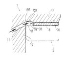
このような基本構成において、上記潤滑油供給路11は、図1に示す如く、一つの軸部13’から隣りの軸部(クランクピン)13に向けて斜めに設けられるようになっているものである。そして、その一方の開口部12は、図2に示す如く、クランクシャフト1の軸部(クランクピン)13の両側面部に形成される肩部15の付け根155のところに設けられるようになっているものである。この付け根155のところには、上記軸部(クランクピン)13の取付部の強度アップを図るために、冷間塑性加工手段であるローラ加工が施されるようになっている。そして、このローラ加工によって、上記付け根155のところには、図2に示す如く、R溝19が形成されるようになっている。そして更に、このR溝19は、図2に示す如く、すべり軸受3の両側端部33の周りに、すべり軸受3の全周にわたって設けられるようになっているものである。また、このR溝19によって空間部121が形成されるようになっているものである。なお、このような構成からなるものにおいて、上記クランクシャフト1の軸部(クランクピン)13のところであって、上記すべり軸受3の軸受面31のほぼ中央部に対向するところには、別の潤滑油供給路である補助給油孔111の開口部113が設けられるようになっている。これによって、すべり軸受3の両側端部33からの潤滑油供給に加えて、この補助給油孔111からの給油が軸受面31に行なわれることとなり、十分な潤滑油供給が行なわれることとなる。なお、この場合、補助給油孔111の開口部113は軸受面31の中央部付近に設けられることとなるが、その開口面積は非常に小さな値のものであるので、油膜の破断等への影響は少なく、実用上問題となることは無い。
【0011】
このような構成からなる本実施の形態のものについての、その作用等について説明する。すなわち、図1に示す如く、本クランクシャフト1及びコネクティングロッド2が作動を開始すると、クランクシャフト1の軸部(クランクピン)13とすべり軸受3の軸受面31との間においては、図3に示す如く、相対回転運動及び相対すべり運動が行なわれることとなる。それに伴って、図1及び図2の矢印図示の如く、潤滑油供給路11及び補助給油孔111を介して、上記すべり軸受3の各部には潤滑油が供給されることとなる。
【0012】
具体的には、まず、図2に示す如く、潤滑油供給路11を流動して来た潤滑油は、上記肩部15の付け根155のところに設けられた開口部12のところに流出して来る(導入される)。そして、この潤滑油は、上記付け根155のところに設けられたR溝19にて形成される空間部121へと導かれ、上記すべり軸受3の両側端部33の、その全周にわたって導入されることとなる。そして更に、このようにすべり軸受3の両側端部33のところに導入された潤滑油は、クランクシャフト1の軸部(クランクピン)13とすべり軸受3の軸受面31との間における相対回転運動中において、例えば図3に示す如く、その円周方向における負圧発生部(AOBの範囲)から、上記軸部(クランクピン)13とすべり軸受3の軸受面31との間の隙間内へと吸引(導入)されることとなる。そして、この隙間(軸受面)に導入された潤滑油は、すべり軸受3の軸受面31の全面にわたって供給されることとなる。その結果、上記軸受面31の全面にわたって正常な油膜が形成されることとなる。
【0013】
また、上記軸部(クランクピン)13のところには、その多くのものにおいては潤滑油供給のための開口部が設けられないようになっているか、あるいは設けられるとしても小さな開口面積を有する補助給油孔111の開口部113が設けられるようになっているにすぎないので(図1参照)、軸受面31の周りには平滑な面が形成されることとなる。従って、クランクシャフト1の軸部(クランクピン)13と上記すべり軸受3の軸受面31との間における相対的なすべり運動(摺動運動)時において、上記摺動面に形成される油膜は、常に正常な状態に保たれることとなる。従って、従来のものにおける如く、給油孔によって、上記油膜が切断(破断)されると言うような不都合の生ずることが無い。
【0014】
また、本実施の形態のものにおいては、上記潤滑油供給のための主たる供給路11の、その開口部12が、軸部(クランクピン)13の上記軸受面31と対向するところではなく、すべり軸受3の両側端部33のところに設けられるようになっているものであるところから、その開口面積を大きく採ることができるようになり、潤滑油を十分に軸受部に供給することができるようになる。すなわち、すべり軸受3の両側端部33のところに、その全周にわたって万遍なく潤滑油を導入することができるようになる。特に、このようにして導入された潤滑油は、上記R溝19にて形成される空間部121を介して、すべり軸受3の両側端部33のところに、その全周にわたって万遍なく供給されることとなる。その結果、軸受面31へは、十分な潤滑油の供給が行なわれることとなり、軸受面31における油膜の形成が確実に行なわれることとなる。また、上記開口部12は、クランクシャフト1の軸部(クランクピン)13の肩部15の、その付け根155のところに設けられるようになっており、クランク半径の最も小さな値を有するところに設けられるようになっているものである。従って、潤滑油に働く遠心力は最も小さな値を有するようになり、供給された潤滑油は遠心力によって飛散させられるようなことがない。その結果、上記潤滑油は、十分に、上記すべり軸受3の軸受面31へと供給されることとなる。
【0015】
【発明の効果】
本発明によれば、クランクシャフトとコネクティングロッドとの連結部に設けられる軸受部への潤滑油の供給機構に関して、上記クランクシャフトの軸部のところであって、上記コネクティングロッドとの間に設けられるすべり軸受の設置される、その両側端部の周りに形成される肩部の付け根のところに、クランクシャフトの軸内に設けられた潤滑油供給路の開口部を設けるようにした構成を採ることとしたので、上記潤滑油供給のための開口部(給油孔)が、軸受面のところではなく、すべり軸受の側端部のところに設けられるようになったことより、その開口面積を大きく採ることができるようになった。その結果、潤滑油を軸受面に十分に供給することができるようになった。すなわち、すべり軸受の両側端部のところに、その全周にわたって万遍なく潤滑油が供給されるようになり、この両側端部のところに供給された潤滑油は、クランクシャフトの軸部とすべり軸受の軸受面との間における相対回転運動中において、その円周方向における負圧発生部から、すべり軸受の軸受面へと吸引(導入)されるようになった。その結果、この隙間(軸受面)に供給された潤滑油は、すべり軸受の軸受面の全面にわたって供給されることとなり、軸受面の全面にわたって正常な油膜が形成されることとなった。
【0016】
また、本発明のものにおいては、上記すべり軸受の軸受面(摺動面)に、潤滑油供給のための大きな開口面積を有する開口部等が設けられておらず、軸受面(摺動面)は平滑な面となっているので、クランクシャフトの軸部と上記すべり軸受の軸受面との間における相対的なすべり運動(摺動運動)時において、上記摺動面に形成された油膜が破断されると言うようなことが無くなった。その結果、常に正常な状態の油膜が確保されるようになり、油膜切れによる軸受部における焼付き現象等の不都合の生ずるおそれが無くなった。
【図面の簡単な説明】
【図1】本発明の全体構成を示す縦断面図である。
【図2】本発明の主要部を成す開口部周りの構造を示す部分断面図である。
【図3】本発明の作動状態を示すスケルトン図である。
【図4】従来例の全体構成を示す縦断面図である。
【符号の説明】
1 クランクシャフト
11 潤滑油供給路
111 補助給油孔
113 開口部
12 開口部(給油孔)
121 空間部
13 軸部(クランクピン)
13’ 軸部
15 肩部
155 付け根
19 R溝
2 コネクティングロッド
3 すべり軸受
31 軸受面
33 側端部[0001]
BACKGROUND OF THE INVENTION
The present invention relates to a mechanism for supplying lubricating oil to a bearing portion provided at a connecting portion between a crankshaft and a connecting rod, and in particular, in the case where the bearing portion is formed of a sliding bearing, the oil film on the bearing surface is broken. The present invention relates to a lubricating oil supply mechanism that prevents the occurrence of the problem.
[0002]
[Prior art]
As shown in FIG. 4, for example, as shown in FIG. 4, a conventional mechanism for supplying lubricating oil to a bearing portion (sliding bearing) in a connecting portion of a crankshaft with a connecting rod is a shaft portion adjacent to a shaft portion 130 ′. It is formed on the basis of a supply path 110 provided obliquely to 130. And one opening 120 of such a supply path 110 is provided in the place which slide-contacts with the bearing surface of the slide bearing 30 provided between the connecting rods 20. . Lubricating oil is supplied to the bearing surface of the slide bearing 30 from the opening 120 as shown by the arrow in FIG. is there.
[0003]
[Problems to be solved by the invention]
In the conventional lubricating oil supply mechanism having such a configuration, the lubricating oil is supplied to the bearing surface which is the contact surface between the slide bearing 30 and the crankshaft shaft portion 130 through the opening 120 of the supply passage 110. Will be. As a result, a predetermined oil film is formed on the bearing surface which is the contact surface between the two. A bearing mechanism is formed between the shaft portion 130 of the crankshaft 10 and the slide bearing 30 via the oil film. By the way, in this conventional one, the opening 120 of the supply passage 110 is provided at a substantially central portion in the width direction of the bearing surface. The opening 120 has a relatively large opening area in order to supply sufficient lubricating oil to the bearing surface of the slide bearing 30. Therefore, when a large load is applied between the shaft portion 130 of the crankshaft 10 and the connecting rod 20, the sliding surface of the slide bearing 30 is subjected to a sliding motion with a large pressure applied. As a result, the oil film formed on the bearing surface may be cut (broken) at the opening 120 having a relatively large opening area. In order to solve such a problem, a lubricating oil supply mechanism for the sliding bearing, which does not have an opening or the like for supplying the lubricating oil at the bearing surface in sliding contact with the sliding bearing, is provided. It is an object (problem) of the present invention to provide.
[0004]
[Means for Solving the Problems]
In order to solve the above problems, the following measures are taken in the present invention. That is, according to the first aspect of the present invention, regarding the supply mechanism of the lubricating oil to the bearing portion provided at the connecting portion between the crankshaft and the connecting rod, the shoulder portions formed on both side portions of the shaft portion of the crankshaft are provided . It is those provided in the base of the place, where the groove is provided as over the entire periphery of both ends of the sliding bearing which is provided between the connecting rod lubricating oil provided in the axis of the crankshaft A configuration was adopted in which an opening of the supply path was provided.
[0005]
By adopting such a configuration, the following effects are exhibited in the present invention. That is, the bearing surface (sliding surface) of the slide bearing that receives a large fluctuating load from the connecting rod is not provided with an oil supply hole (opening) for supplying lubricating oil. ) Is a smooth surface, the oil film formed on the sliding surface during relative sliding motion (sliding motion) between the shaft portion of the crankshaft and the bearing surface of the sliding bearing is It will always be kept in a normal state. Accordingly, there is no inconvenience that the oil film is cut (broken) by the oil supply hole as in the conventional one. In particular, in the bearing surface with the connecting rod that receives a shocking variable load from the piston, the presence of discontinuities due to oil supply holes or the like adversely affects the retention of the oil film. From these facts, as in the present invention, in the case of a structure that does not have an opening (oil supply hole) for supplying lubricating oil on the bearing surface, it exhibits an excellent ability to hold an oil film. Become.
[0006]
Moreover, in the thing of this invention, the opening part (oil supply hole) for the said lubricating oil supply is provided not in the place of a bearing surface but in the side edge part of a slide bearing. Therefore, the opening area can be increased, and the lubricating oil can be sufficiently supplied to the bearing portion. That is, the lubricating oil can be supplied uniformly over the entire circumference through the space formed at the both end portions of the slide bearing. Then, the lubricating oil supplied to both ends of the slide bearing in this way is subjected to relative rotational movement between the shaft portion of the crankshaft and the bearing surface of the slide bearing, for example, as shown in FIG. The negative pressure generating portion in the circumferential direction is sucked (introduced) into the gap between the shaft portion and the bearing surface of the slide bearing. The lubricating oil supplied to the gap (bearing surface) is introduced over the entire bearing surface of the slide bearing. As a result, a normal oil film is formed over the entire bearing surface.
[0007]
Next, a second invention according to claim 1 will be described. The basic point of this is the same as that of the first invention. The feature is that the opening (oil supply hole) of the lubricating oil supply passage is formed at the shaft portion of the crankshaft and around both side end portions of the slide bearing provided between the connecting rod and the connecting rod. The shoulder portion is provided at an R groove provided at the base of the shoulder portion and at a place where the crank radius has a minimum value. Generally, at the base of the shoulder portion, roller processing based on cold plastic processing means is applied in order to improve the strength of the shaft portion. By this roller processing, an R groove is formed at the base of the shoulder. By providing an opening at the R groove, an oil supply hole having a large opening area can be formed, and sufficient lubricating oil can be supplied.
[0008]
Further, the lubricating oil supplied in this way is supplied uniformly over the entire circumference to the side end portion of the slide bearing through the R groove. As a result, sufficient lubrication oil is supplied to the bearing surface, and an oil film is reliably formed on the bearing surface. Further, the opening (oil supply hole) is provided at the base of the shoulder portion of the shaft portion of the crankshaft, and is provided at the place having the smallest value of the crank radius. It is what. Accordingly, the centrifugal force acting on the lubricating oil has the smallest value, and the supplied lubricating oil is not scattered by the centrifugal force. As a result, the lubricating oil is sufficiently supplied to the bearing surface of the slide bearing.
[0009]
DETAILED DESCRIPTION OF THE INVENTION
An embodiment of the present invention will be described with reference to FIGS. As shown in FIG. 1, the configuration of the embodiment of the present invention is such that a relative rotational motion is possible at the crankshaft 1 and the shaft portion (crankpin) 13 of the crankshaft 1, and A connecting rod 2 connected so as to be capable of relative sliding movement, a sliding bearing 3 provided at a connecting portion between the connecting rod 2 and a shaft portion (crank pin) 13 of the crankshaft 1, and the crank The lubricating oil supply passage 11 is provided in the shaft of the shaft 1 and has an opening 12 provided around both side end portions 33 of the slide bearing 3.
[0010]
In such a basic configuration, the lubricating oil supply passage 11 is provided obliquely from one shaft portion 13 ′ toward the adjacent shaft portion (crank pin) 13 as shown in FIG. 1. It is. As shown in FIG. 2, the one opening 12 is provided at the base 155 of the shoulder 15 formed on both sides of the shaft (crank pin) 13 of the crankshaft 1. Is. In order to increase the strength of the mounting portion of the shaft portion (crank pin) 13, the base portion 155 is subjected to roller processing which is a cold plastic processing means. By this roller processing, an R groove 19 is formed at the base 155 as shown in FIG. Further, as shown in FIG. 2, the R groove 19 is provided around the both ends 33 of the slide bearing 3 over the entire circumference of the slide bearing 3. Further, a space 121 is formed by the R groove 19. In the structure having such a configuration, another lubrication is provided at the shaft portion (crank pin) 13 of the crankshaft 1, which is opposed to the substantially central portion of the bearing surface 31 of the slide bearing 3. An opening 113 of an auxiliary oil supply hole 111 that is an oil supply path is provided. As a result, in addition to supplying the lubricating oil from the both end portions 33 of the slide bearing 3, the lubricating oil is supplied from the auxiliary oil supply hole 111 to the bearing surface 31, and sufficient lubricating oil is supplied. In this case, the opening 113 of the auxiliary oil supply hole 111 is provided in the vicinity of the center of the bearing surface 31, but the opening area has a very small value. There is no problem in practical use.
[0011]
The operation and the like of this embodiment configured as described above will be described. That is, as shown in FIG. 1, when the crankshaft 1 and the connecting rod 2 start operating, the space between the shaft portion (crank pin) 13 of the crankshaft 1 and the bearing surface 31 of the slide bearing 3 is shown in FIG. As shown, a relative rotational motion and a relative sliding motion are performed. Accordingly, as shown by the arrows in FIGS. 1 and 2, the lubricating oil is supplied to each part of the slide bearing 3 through the lubricating oil supply passage 11 and the auxiliary oil supply hole 111.
[0012]
Specifically, first, as shown in FIG. 2, the lubricating oil flowing through the lubricating oil supply passage 11 flows out to the opening 12 provided at the base 155 of the shoulder 15. Come (introduced). The lubricating oil is guided to the space 121 formed by the R groove 19 provided at the base 155 and is introduced over the entire circumference of both side end portions 33 of the sliding bearing 3. It will be. Further, the lubricating oil introduced into the both end portions 33 of the slide bearing 3 in this way is relatively rotated between the shaft portion (crank pin) 13 of the crankshaft 1 and the bearing surface 31 of the slide bearing 3. In the inside, for example, as shown in FIG. 3, from the negative pressure generating portion (AOB range) in the circumferential direction into the gap between the shaft portion (crank pin) 13 and the bearing surface 31 of the slide bearing 3. It will be sucked (introduced). The lubricating oil introduced into this gap (bearing surface) is supplied over the entire bearing surface 31 of the sliding bearing 3. As a result, a normal oil film is formed over the entire bearing surface 31.
[0013]
Further, in many of the shaft portions (crank pins) 13, an opening for supplying lubricating oil is not provided, or an auxiliary having a small opening area even if provided. Since only the opening 113 of the oil supply hole 111 is provided (see FIG. 1), a smooth surface is formed around the bearing surface 31. Therefore, the oil film formed on the sliding surface during the relative sliding motion (sliding motion) between the shaft portion (crank pin) 13 of the crankshaft 1 and the bearing surface 31 of the sliding bearing 3 is: It will always be kept in a normal state. Accordingly, there is no inconvenience that the oil film is cut (broken) by the oil supply hole as in the conventional one.
[0014]
Further, in the present embodiment, the opening 12 of the main supply passage 11 for supplying the lubricating oil is not a place facing the bearing surface 31 of the shaft (crank pin) 13, but slipping. Since it is provided at the both end portions 33 of the bearing 3, the opening area can be increased, and the lubricating oil can be sufficiently supplied to the bearing portion. become. That is, the lubricating oil can be uniformly introduced to the both end portions 33 of the slide bearing 3 over the entire circumference. In particular, the lubricating oil introduced in this way is supplied uniformly over the entire circumference to the side end portions 33 of the slide bearing 3 through the space 121 formed by the R groove 19. The Rukoto. As a result, a sufficient amount of lubricating oil is supplied to the bearing surface 31, and an oil film is reliably formed on the bearing surface 31. The opening 12 is provided at the base 155 of the shoulder portion 15 of the shaft portion (crank pin) 13 of the crankshaft 1 and has the smallest value of the crank radius. It is supposed to be. Therefore, the centrifugal force acting on the lubricating oil has the smallest value, and the supplied lubricating oil is not scattered by the centrifugal force. As a result, the lubricating oil is sufficiently supplied to the bearing surface 31 of the sliding bearing 3.
[0015]
【The invention's effect】
According to the present invention, with respect to a mechanism for supplying lubricating oil to the bearing portion provided at the connecting portion between the crankshaft and the connecting rod, the slip provided at the shaft portion of the crankshaft and between the connecting rod. Adopting a configuration in which an opening of a lubricating oil supply passage provided in the shaft of the crankshaft is provided at the base of a shoulder portion formed around both ends of the bearing where the bearing is installed. Therefore, the opening for supplying the lubricating oil (oil supply hole) is provided not at the bearing surface but at the side end of the slide bearing, so that the opening area is increased. Can now. As a result, the lubricating oil can be sufficiently supplied to the bearing surface. In other words, the lubricating oil is uniformly supplied to the end portions on both sides of the slide bearing over the entire circumference, and the lubricating oil supplied to the end portions on both sides of the sliding bearing and the shaft portion of the crankshaft. During the relative rotational movement between the bearing surface and the bearing surface, suction (introduction) is started from the negative pressure generating portion in the circumferential direction to the bearing surface of the slide bearing. As a result, the lubricating oil supplied to the gap (bearing surface) is supplied over the entire bearing surface of the slide bearing, and a normal oil film is formed over the entire bearing surface.
[0016]
In the present invention, the bearing surface (sliding surface) of the slide bearing is not provided with an opening or the like having a large opening area for supplying lubricating oil, and the bearing surface (sliding surface). Since this is a smooth surface, the oil film formed on the sliding surface breaks during the relative sliding motion (sliding motion) between the shaft portion of the crankshaft and the bearing surface of the sliding bearing. There was no such thing as being said. As a result, an oil film in a normal state is always ensured, and there is no possibility of inconvenience such as seizure phenomenon in the bearing portion due to the oil film running out.
[Brief description of the drawings]
FIG. 1 is a longitudinal sectional view showing an overall configuration of the present invention.
FIG. 2 is a partial cross-sectional view showing a structure around an opening constituting the main part of the present invention.
FIG. 3 is a skeleton diagram showing an operating state of the present invention.
FIG. 4 is a longitudinal sectional view showing an overall configuration of a conventional example.
[Explanation of symbols]
DESCRIPTION OF SYMBOLS 1 Crankshaft 11 Lubricating oil supply path 111 Auxiliary oil supply hole 113 Opening part 12 Opening part (oil supply hole)
121 Space 13 Shaft (Crankpin)
13 'shaft portion 15 shoulder portion 155 base 19 R groove 2 connecting rod 3 slide bearing 31 bearing surface 33 side end portion