JP3607771B2 - Transfer paper transport device - Google Patents
Transfer paper transport device Download PDFInfo
- Publication number
- JP3607771B2 JP3607771B2 JP07449596A JP7449596A JP3607771B2 JP 3607771 B2 JP3607771 B2 JP 3607771B2 JP 07449596 A JP07449596 A JP 07449596A JP 7449596 A JP7449596 A JP 7449596A JP 3607771 B2 JP3607771 B2 JP 3607771B2
- Authority
- JP
- Japan
- Prior art keywords
- transfer paper
- transfer
- fixing
- fixing roller
- roller
- Prior art date
- Legal status (The legal status is an assumption and is not a legal conclusion. Google has not performed a legal analysis and makes no representation as to the accuracy of the status listed.)
- Expired - Fee Related
Links
Images


Description
【0001】
【発明の属する技術分野】
本発明は、電子写真装置において、定着器に転写紙を搬送する転写紙搬送装置に関する。
【0002】
【従来の技術】
電子写真装置に利用される定着器は、像担持体に形成された画像が転写器により転写された転写紙を、定着ローラと加圧ローラとで挾持しながら搬送する過程で転写紙上の転写画像を定着する型式のものが多用されている。このような定着器では、転写紙の画像転写面が定着ローラに巻き付くことを防止するために、定着ローラの表面には、転写紙の剥離性を高めるための処理が施されているとともに、離型剤としてシリコンオイル等のオイルが塗布され、さらに、剥離爪のエッジが定着ローラに接触されている。
【0003】
しかしながら、定着ローラの少なくとも定着有効領域はゴム等の弾性部材により形成されている場合が多く、その部分は摩耗し易い。最大幅以下の転写紙の場合には、必ずエッジの部分が定着有効領域を通過するので、長期間使用すると定着有効領域の表面は転写紙のエッジとの接触により摩耗する。この摩耗が進行すると、定着ローラの表面には周方向に筋状に傷がつき、その傷が発生した部分にオイルが入り込み、このオイルにより転写紙の両側部分を汚してしまう。
【0004】
このようなことから、特開平2−271377号公報に記載されているように、定着ローラを軸方向に移動させることにより、定着ローラの摩耗部分を分散するようにした定着装置が提案されている。具体的には、定着ローラを一定の範囲内で軸方向に移動自在に支持し、加圧ローラの両端をばねにより定着ローラ側に付勢し、定着ローラの両端における加圧ローラの圧接力の差により定着ローラを軸方向に変位させるものである。
【0005】
【発明が解決しようとする課題】
特開平2−271377号公報に記載された定着装置は、定着ローラに対する加圧ローラの圧接力が小さい方向に定着ローラが軸方向に移動するので、定着ローラを途中で止めることはできない。すなわち、転写紙のエッジとの接触により定着ローラの外周に円周方向に沿って摩耗するリング状の傷の位置が、定着ローラの移動範囲に相当する間隔を開けて変化するだけであり、摩耗個所を連続的に分散させることはできない。これにより、定着ローラの寿命を延長するには限度がある。
【0006】
【課題を解決するための手段】
請求項1記載の発明は、像担持体の表面に形成された画像を転写紙に転写する転写器と、定着ローラとこの定着ローラに圧接された加圧ローラとを有して前記転写器を通過した転写紙上の転写画像を定着する定着器と、転写紙を前記転写器から前記定着器に向けて搬送する転写紙搬送機構と、この転写紙搬送機構中に配置されて転写紙を所定角度斜行させる斜行機構とを備え、前記斜行機構は、転写紙の幅が最大幅であることを認識したときに停止状態に維持される。したがって、1枚の転写紙が定着ローラを通過するときに、転写紙のエッジは定着ローラとの接触位置を定着ローラの軸方向に移動しながら搬送されるため、定着ローラの定着有効領域に対する転写紙のエッジの接触部分が連続的に変化する。さらに、最大幅の転写紙は、左右の余白を考慮すると、エッジ部分を摩耗し易い定着有効領域の外側を通過することも可能であるので、転写紙を斜行させないことにより、定着ローラの全長を必要以上に長くする必要性がなくなる。
【0009】
【発明の実施の形態】
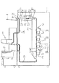
本発明の実施の一形態を図面に基づいて説明する。まず、図1に電子写真装置の全体構造を示す。1は装置本体である。この装置本体1の中心部には、上下方向に駆動される転写ベルト2が設けられ、この転写ベルト2の回転方向に沿ってそれぞれ異なる色の画像を形成する画像形成部3が配列されている。装置本体1の外側には、積層された転写紙4を一枚ずつ給紙する給紙ユニット5、両面印刷モードが指定されたときに印刷済みの転写紙4を再給紙する両面給紙ユニット6、排紙トレイ7が設けられている。また、装置本体1には、給紙ユニット5及び両面給紙ユニット6から転写ベルト2の下部に向けて転写紙4を搬送する搬送路8が設けられている。
【0010】
前記画像形成部3は、像担持体9の表面を帯電器10により帯電させ、その帯電部分に光書込器11によりレーザー光を走査して静電潜像を形成し、その静電潜像を現像器12により現像し、転写ベルト2により搬送される転写紙4に像担持体9上の現像画像を転写器13により転写した後に、像担持体9を除電ランプ14により除電する構造である。
【0011】
また、装置本体1の上部には、転写ベルト2の上部から転写紙4を分離させる分離チャージャ15、転写ベルト2から分離した転写紙4を定着器19に搬送する転写紙搬送機構17、定着器16を通過した転写紙4を排紙する排紙ローラ18,19、排紙ローラ18により排紙される転写紙4を前記両面給紙ユニット6に通じる通路20と前記排紙トレイ7とに選択的に導く回動自在の切替爪21が設けられている。転写紙搬送機構17の上部には、定着効率を高めるために、ヒータ22とファン23とよりなるプレヒート装置24が設けられている。定着器16は定着ローラ25と、この定着ローラ25に圧接された加圧ローラ26とにより形成されている。さらに、転写紙搬送機構17には、転写紙4を所定角度斜行させる斜行機構27が設けられている。
【0012】
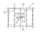
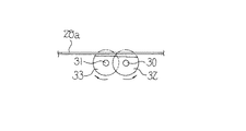
図2及び図3に示すように、前記転写紙搬送機構17は、転写紙4を支えるガイド板28aと、転写紙4の幅方向に位置が調節されるサイドフェンス28と、モータ(図示せず)により駆動される複数本の搬送ローラ29とよりなる。また、前記斜行機構27は、サイドフェンス28の離反空間の略中心において搬送ローラ29と直交する二本のローラ軸30,31と、これらのローラ軸30,31の相反する方向の端部に固定された斜行ローラ32,33と、ローラ軸30,31の中間部に固定されて互いに噛合されたギヤ34,35と、正逆回転自在のモータ(図示せず)に連結されてローラ軸30の端部に固定された駆動伝達部材36と、転写紙4の先端を検出したときにモータを駆動して駆動伝達部材36を一回転させる信号を出力するセンサ37よりなる。図4に示すように、斜行ローラ32,33は外周の一部が切り欠かれたD字形をしており、通常は切り欠かれた部分が上方に向いた状態で静止し、転写紙4に触れることはない。
【0013】
このような構成において、転写ベルト2により搬送され画像形成部3を通過した転写紙4は、転写紙搬送機構17により定着器16に搬送される。このときに、転写紙4の先端をセンサ37が検出すると、モータが回転し駆動伝達部材36がローラ軸30及び斜行ローラ32と共に一回転する。ローラ軸30の回転はギヤ34,35によりローラ軸31に伝達されるため、斜行ローラ33は斜行ローラ32とは反対方向に一回転する。すなわち、転写紙4は上流側の部分が図2において下方に寄せられ、下流側の部分が図2において上方に寄せられるために、点線に示す真っ直ぐの状態から実線に示すように傾けられ、この状態で搬送ローラ29により定着器16に搬送される。このときの転写紙4の傾斜角は、転写紙4のサイズに応じて転写紙4の幅方向に位置を調整されたサイドフェンス28により規制される。
【0014】
これにより、図5に示すように、転写紙4は定着ローラ25を通過するときに、定着ローラ25の定着有効領域(図示せず)に対する転写紙4のエッジの接触部分が、定着ローラ25の軸方向にaなる寸法の範囲(ハッチングで示す範囲)だけ連続的に変化する。したがって、定着ローラ25が局部的に摩耗することがなく、寿命を延長させることができる。これは請求項1記載の発明に対応する効果である。
【0015】
この場合、転写紙4の傾きを大きくし過ぎると定着ローラ25の全長を長くしなければならないので、1°ないし5°程度が適切である。長辺が420mmのA4サイズの転写紙4を例にすると、傾斜角は3°に定められ、図5におけるaは22mm弱になる。
【0016】
また、モータの回転方向を変え、駆動伝達部材36の回転方向を逆にすると、斜行ローラ32,33の回転方向が変わるため、図6に示すように、転写紙4の斜行方向を対称方向に切り替えることができる。これにより、印刷済みの転写紙4を排紙トレイ7に排紙するときには、定着ローラ25から排紙された転写紙4の向きを変えることができる。これに伴い、二種類の印刷物を一つの排紙トレイ7上で分けて積載する使い方をすることができる。これは請求項2記載の発明に対応する効果である。すなわち、駆動伝達部材36は、転写紙4の斜行方向を対称方向に選択的に切り替える切替部として機能する。
【0017】
さらに、転写紙4のサイズは操作部(図示せず)に指定され、あるいは、サイズ検出器(図示せず)により検出されるが、図7に示すように、最大幅以下の転写紙4Sであると認識された場合には、前述したように斜行機構27により転写紙4Sを傾けるが、最大幅の転写紙4Lであると認識された場合には、左右の余白を考慮すると、エッジ部分を摩耗し易い定着有効領域の外側を通過させることも可能であるので、斜行機構27を停止させることにより、定着ローラ25の全長を必要以上に伸ばす必要がなくなり、これに伴い装置の小型化に寄与することができる。これは請求項3記載の発明に対応する効果である。この場合、最大幅の転写紙4Lが通る定着ローラ25の部分には、転写紙4より薄い耐摩耗性のシート等を巻回することが望ましい。
【0018】
【発明の効果】
請求項1記載の発明は、像担持体の表面に形成された画像を転写紙に転写する転写器と、定着ローラとこの定着ローラに圧接された加圧ローラとを有して前記転写器を通過した転写紙上の転写画像を定着する定着器と、転写紙を前記転写器から前記定着器に向けて搬送する転写紙搬送機構と、この転写紙搬送機構中に配置されて転写紙を所定角度斜行させる斜行機構とを備えているので、1枚の転写紙が定着ローラを通過するときに、転写紙のエッジは定着ローラとの接触位置を定着ローラの軸方向に移動しながら搬送されるため、定着ローラの定着有効領域に対する転写紙のエッジの接触部分を連続的に変化させることができる。したがって、定着ローラの局部的な摩耗を防止し、寿命を延長させることができる。さらに、斜行機構は、転写紙の幅が最大幅であることを認識したときに停止状態に維持されるので、左右の余白を考慮すると、エッジ部分を摩耗し易い定着有効領域の外側を通過させ得るような最大幅の転写紙を用いる場合には、斜行機構を停止状態に維持し、転写紙を斜行させずに定着器に搬送することができる。これにより、定着ローラの全長を必要以上に長くする必要性をなくし、装置の小型化に寄与することができる。
【図面の簡単な説明】
【図1】本発明の実施の一形態における電子写真装置の全体構造を示す縦断側面図である。
【図2】転写紙搬送機構及び斜行機構を示す平面図である。
【図3】転写紙搬送機構及び斜行機構を示す側面図である。
【図4】斜行機構の背面図である。
【図5】定着ローラと転写紙との関係を示す平面図である。
【図6】転写紙を対称方向に傾けた状態を示す平面図である。
【図7】定着ローラと転写紙との関係を示す平面図である。
【符号の説明】
4 転写紙
9 像担持体
13 転写器
16 定着器
17 転写紙搬送機構
25 定着ローラ
26 加圧ローラ
27 斜行機構
36 切替部[0001]
BACKGROUND OF THE INVENTION
The present invention relates to a transfer paper transport device for transporting transfer paper to a fixing device in an electrophotographic apparatus.
[0002]
[Prior art]
The fixing device used in the electrophotographic apparatus transfers the transfer image on the transfer paper in the process of conveying the transfer paper on which the image formed on the image carrier is transferred by the transfer device while being held between the fixing roller and the pressure roller. Often used to fix this. In such a fixing device, in order to prevent the image transfer surface of the transfer paper from being wound around the fixing roller, the surface of the fixing roller is subjected to a process for improving the peelability of the transfer paper, Oil such as silicone oil is applied as a release agent, and the edge of the peeling claw is in contact with the fixing roller.
[0003]
However, at least the fixing effective region of the fixing roller is often formed by an elastic member such as rubber, and the portion is easily worn. In the case of transfer paper having a width less than the maximum width, the edge portion always passes through the effective fixing area, so that the surface of the effective fixing area is worn by contact with the edge of the transfer paper when used for a long time. As this wear progresses, the surface of the fixing roller is flawed in the circumferential direction, and oil enters the part where the flaw occurs, and this oil stains both sides of the transfer paper.
[0004]
For this reason, as described in JP-A-2-271377, there has been proposed a fixing device that disperses the worn portion of the fixing roller by moving the fixing roller in the axial direction. . Specifically, the fixing roller is supported so as to be movable in the axial direction within a certain range, both ends of the pressure roller are urged toward the fixing roller by springs, and the pressure contact force of the pressure roller at both ends of the fixing roller is reduced. The fixing roller is displaced in the axial direction by the difference.
[0005]
[Problems to be solved by the invention]
In the fixing device described in Japanese Patent Application Laid-Open No. 2-271377, the fixing roller moves in the axial direction in a direction where the pressure contact force of the pressure roller with respect to the fixing roller is small, and therefore the fixing roller cannot be stopped halfway. That is, the position of the ring-shaped flaw that wears along the circumferential direction on the outer periphery of the fixing roller due to contact with the edge of the transfer paper only changes at an interval corresponding to the moving range of the fixing roller. The locations cannot be dispersed continuously. Accordingly, there is a limit to extending the life of the fixing roller.
[0006]
[Means for Solving the Problems]
According to a first aspect of the present invention, there is provided a transfer device for transferring an image formed on the surface of an image carrier onto a transfer sheet, a fixing roller, and a pressure roller pressed against the fixing roller. A fixing device that fixes the transferred image on the transferred transfer paper, a transfer paper transport mechanism that transports the transfer paper from the transfer device to the fixing device, and a transfer paper that is disposed in the transfer paper transport mechanism at a predetermined angle. A skew feeding mechanism for skewing, and the skew feeding mechanism is maintained in a stopped state when it is recognized that the width of the transfer sheet is the maximum width . Accordingly, when one sheet of transfer paper passes through the fixing roller, the edge of the transfer paper is conveyed while moving the contact position with the fixing roller in the axial direction of the fixing roller. The contact portion of the paper edge changes continuously. Furthermore, considering the left and right margins, the maximum width transfer paper can pass outside the effective fixing area where the edge portion easily wears. There is no need to make it longer than necessary .
[0009]
DETAILED DESCRIPTION OF THE INVENTION
An embodiment of the present invention will be described with reference to the drawings. First, FIG. 1 shows the overall structure of the electrophotographic apparatus. Reference numeral 1 denotes an apparatus main body. A transfer belt 2 that is driven in the vertical direction is provided at the center of the apparatus body 1, and image forming units 3 that form images of different colors are arranged along the rotation direction of the transfer belt 2. . Outside the apparatus main body 1 are a paper feed unit 5 that feeds the laminated
[0010]
The image forming unit 3 charges the surface of the image carrier 9 with a
[0011]
In addition, a separation charger 15 that separates the
[0012]
2 and 3, the transfer
[0013]
In such a configuration, the
[0014]
As a result, as shown in FIG. 5, when the
[0015]
In this case, if the inclination of the
[0016]
Further, if the rotation direction of the motor is changed and the rotation direction of the drive transmission member 36 is reversed, the rotation direction of the
[0017]
Further, the size of the
[0018]
【The invention's effect】
According to a first aspect of the present invention, there is provided a transfer device for transferring an image formed on the surface of an image carrier onto a transfer sheet, a fixing roller, and a pressure roller pressed against the fixing roller. A fixing device that fixes the transferred image on the transferred transfer paper, a transfer paper transport mechanism that transports the transfer paper from the transfer device to the fixing device, and a transfer paper that is disposed in the transfer paper transport mechanism at a predetermined angle. Since the skew feeding mechanism is provided, the edge of the transfer paper is conveyed while moving the contact position with the fixing roller in the axial direction of the fixing roller when one transfer paper passes the fixing roller. Therefore, the contact portion of the transfer paper edge with respect to the fixing effective area of the fixing roller can be continuously changed. Therefore, local wear of the fixing roller can be prevented and the life can be extended. Furthermore, since the skew feeding mechanism is maintained in a stopped state when it recognizes that the width of the transfer sheet is the maximum width, considering the left and right margins, it passes outside the effective fixing area where the edge portion is easily worn. When the transfer paper having the maximum width that can be used is used, the skew feeding mechanism is maintained in the stopped state, and the transfer paper can be conveyed to the fixing device without being skewed. This eliminates the need for making the entire length of the fixing roller longer than necessary, and contributes to the downsizing of the apparatus .
[Brief description of the drawings]
FIG. 1 is a longitudinal side view showing an overall structure of an electrophotographic apparatus according to an embodiment of the present invention.
FIG. 2 is a plan view showing a transfer paper transport mechanism and a skew feeding mechanism.
FIG. 3 is a side view showing a transfer paper transport mechanism and a skew feeding mechanism.
FIG. 4 is a rear view of the skew mechanism.
FIG. 5 is a plan view showing a relationship between a fixing roller and transfer paper.
FIG. 6 is a plan view showing a state in which the transfer paper is tilted in a symmetric direction.
FIG. 7 is a plan view showing the relationship between the fixing roller and transfer paper.
[Explanation of symbols]
4 Transfer paper 9 Image carrier 13
Claims (1)
Priority Applications (1)
| Application Number | Priority Date | Filing Date | Title |
|---|---|---|---|
| JP07449596A JP3607771B2 (en) | 1996-03-28 | 1996-03-28 | Transfer paper transport device |
Applications Claiming Priority (1)
| Application Number | Priority Date | Filing Date | Title |
|---|---|---|---|
| JP07449596A JP3607771B2 (en) | 1996-03-28 | 1996-03-28 | Transfer paper transport device |
Publications (2)
| Publication Number | Publication Date |
|---|---|
| JPH09265219A JPH09265219A (en) | 1997-10-07 |
| JP3607771B2 true JP3607771B2 (en) | 2005-01-05 |
Family
ID=13548952
Family Applications (1)
| Application Number | Title | Priority Date | Filing Date |
|---|---|---|---|
| JP07449596A Expired - Fee Related JP3607771B2 (en) | 1996-03-28 | 1996-03-28 | Transfer paper transport device |
Country Status (1)
| Country | Link |
|---|---|
| JP (1) | JP3607771B2 (en) |
Families Citing this family (4)
| Publication number | Priority date | Publication date | Assignee | Title |
|---|---|---|---|---|
| KR100854088B1 (en) * | 2006-02-24 | 2008-08-25 | 삼성전자주식회사 | Fusing system of image forming apparatus and method for controlling thereof |
| JP2011022305A (en) | 2009-07-15 | 2011-02-03 | Konica Minolta Business Technologies Inc | Image forming apparatus |
| JP5212295B2 (en) | 2009-07-21 | 2013-06-19 | コニカミノルタビジネステクノロジーズ株式会社 | Image forming apparatus |
| JP5445251B2 (en) * | 2010-03-16 | 2014-03-19 | 株式会社リコー | Image forming apparatus |
-
1996
- 1996-03-28 JP JP07449596A patent/JP3607771B2/en not_active Expired - Fee Related
Also Published As
| Publication number | Publication date |
|---|---|
| JPH09265219A (en) | 1997-10-07 |
Similar Documents
| Publication | Publication Date | Title |
|---|---|---|
| JP2007326708A (en) | Off-center adjusting device | |
| JP3257712B2 (en) | Transport path switching device | |
| JP3607771B2 (en) | Transfer paper transport device | |
| JP4439461B2 (en) | Image forming apparatus and switchback transport mechanism | |
| US7588248B2 (en) | Sheet conveying device and image forming apparatus | |
| JP6225434B2 (en) | Image forming apparatus | |
| JP4254722B2 (en) | Image forming apparatus | |
| JP3488662B2 (en) | Sheet member transport mechanism of image forming apparatus | |
| JP2007022736A (en) | Recording paper inverting device, image forming device, electrophotographic copying machine, laser beam printer, facsimile, and scanner | |
| JP2007045541A (en) | Inversion device, image formation device, electrophotograph copier, facsimile, printer and scanner | |
| JPH09319168A (en) | Copying machine/printer | |
| JP3919451B2 (en) | Image forming apparatus | |
| JP4007487B2 (en) | Image forming apparatus | |
| JP3809370B2 (en) | Image forming apparatus | |
| JP2007045542A (en) | Cleaning device and image formation device | |
| JP4042221B2 (en) | Image forming apparatus | |
| JP2001097622A (en) | Image forming device | |
| JP3113640B2 (en) | Paper transport device | |
| JP3702558B2 (en) | Image forming apparatus | |
| JP2000211773A (en) | Image forming device | |
| JP2006143410A (en) | Image forming apparatus | |
| JPH10203693A (en) | Automatic document carrying device | |
| JP3967068B2 (en) | Image forming apparatus | |
| JP2004250146A (en) | Paper inversion device | |
| JPH061497A (en) | Skew prevention mechanism for recording sheet |
Legal Events
| Date | Code | Title | Description |
|---|---|---|---|
| A977 | Report on retrieval |
Free format text: JAPANESE INTERMEDIATE CODE: A971007 Effective date: 20040623 |
|
| A131 | Notification of reasons for refusal |
Free format text: JAPANESE INTERMEDIATE CODE: A131 Effective date: 20040715 |
|
| A521 | Written amendment |
Free format text: JAPANESE INTERMEDIATE CODE: A523 Effective date: 20040907 |
|
| TRDD | Decision of grant or rejection written | ||
| A01 | Written decision to grant a patent or to grant a registration (utility model) |
Free format text: JAPANESE INTERMEDIATE CODE: A01 Effective date: 20041005 |
|
| A61 | First payment of annual fees (during grant procedure) |
Free format text: JAPANESE INTERMEDIATE CODE: A61 Effective date: 20041008 |
|
| R150 | Certificate of patent (=grant) or registration of utility model |
Free format text: JAPANESE INTERMEDIATE CODE: R150 |
|
| FPAY | Renewal fee payment (prs date is renewal date of database) |
Free format text: PAYMENT UNTIL: 20071015 Year of fee payment: 3 |
|
| FPAY | Renewal fee payment (prs date is renewal date of database) |
Free format text: PAYMENT UNTIL: 20081015 Year of fee payment: 4 |
|
| FPAY | Renewal fee payment (prs date is renewal date of database) |
Free format text: PAYMENT UNTIL: 20081015 Year of fee payment: 4 |
|
| FPAY | Renewal fee payment (prs date is renewal date of database) |
Free format text: PAYMENT UNTIL: 20091015 Year of fee payment: 5 |
|
| FPAY | Renewal fee payment (prs date is renewal date of database) |
Free format text: PAYMENT UNTIL: 20101015 Year of fee payment: 6 |
|
| LAPS | Cancellation because of no payment of annual fees |