JP3607672B2 - Magnetic disk apparatus of perpendicular magnetic recording system and recording compensation method applied to the same - Google Patents
Magnetic disk apparatus of perpendicular magnetic recording system and recording compensation method applied to the same Download PDFInfo
- Publication number
- JP3607672B2 JP3607672B2 JP2001367848A JP2001367848A JP3607672B2 JP 3607672 B2 JP3607672 B2 JP 3607672B2 JP 2001367848 A JP2001367848 A JP 2001367848A JP 2001367848 A JP2001367848 A JP 2001367848A JP 3607672 B2 JP3607672 B2 JP 3607672B2
- Authority
- JP
- Japan
- Prior art keywords
- recording
- magnetic
- disturbance
- magnetic field
- head
- Prior art date
- Legal status (The legal status is an assumption and is not a legal conclusion. Google has not performed a legal analysis and makes no representation as to the accuracy of the status listed.)
- Expired - Fee Related
Links
Images


Classifications
-
- G—PHYSICS
- G11—INFORMATION STORAGE
- G11B—INFORMATION STORAGE BASED ON RELATIVE MOVEMENT BETWEEN RECORD CARRIER AND TRANSDUCER
- G11B5/00—Recording by magnetisation or demagnetisation of a record carrier; Reproducing by magnetic means; Record carriers therefor
- G11B5/012—Recording on, or reproducing or erasing from, magnetic disks
-
- G—PHYSICS
- G11—INFORMATION STORAGE
- G11B—INFORMATION STORAGE BASED ON RELATIVE MOVEMENT BETWEEN RECORD CARRIER AND TRANSDUCER
- G11B5/00—Recording by magnetisation or demagnetisation of a record carrier; Reproducing by magnetic means; Record carriers therefor
- G11B5/02—Recording, reproducing, or erasing methods; Read, write or erase circuits therefor
- G11B5/09—Digital recording
-
- G—PHYSICS
- G11—INFORMATION STORAGE
- G11B—INFORMATION STORAGE BASED ON RELATIVE MOVEMENT BETWEEN RECORD CARRIER AND TRANSDUCER
- G11B5/00—Recording by magnetisation or demagnetisation of a record carrier; Reproducing by magnetic means; Record carriers therefor
- G11B2005/0002—Special dispositions or recording techniques
- G11B2005/0005—Arrangements, methods or circuits
- G11B2005/001—Controlling recording characteristics of record carriers or transducing characteristics of transducers by means not being part of their structure
- G11B2005/0013—Controlling recording characteristics of record carriers or transducing characteristics of transducers by means not being part of their structure of transducers, e.g. linearisation, equalisation
-
- G—PHYSICS
- G11—INFORMATION STORAGE
- G11B—INFORMATION STORAGE BASED ON RELATIVE MOVEMENT BETWEEN RECORD CARRIER AND TRANSDUCER
- G11B5/00—Recording by magnetisation or demagnetisation of a record carrier; Reproducing by magnetic means; Record carriers therefor
- G11B2005/0002—Special dispositions or recording techniques
- G11B2005/0026—Pulse recording
- G11B2005/0029—Pulse recording using magnetisation components of the recording layer disposed mainly perpendicularly to the record carrier surface
Description
【0001】
【発明の属する技術分野】
本発明は、一般的には垂直磁気記録方式の磁気ディスク装置に関し、特に、外乱磁界に起因する記録歪みを補償する記録補償技術に関する。
【0002】
【従来の技術】
近年、ハードディスクドライブを代表とする磁気ディスク装置(以下ディスクドライブと呼ぶ場合がある)の分野では、長手磁気記録方式での記録密度の限界を超えるための技術として、垂直磁気記録方式が注目されている。
【0003】
ところで、従来の長手磁気記録方式のディスクドライブでは、ディスク媒体上に記録された磁気記録データにおいて、隣接ビットパターンの影響により磁化転移位置(信号反転位置)が正規の位置より前方にシフトする非線形ビットシフトが起こる。このような記録歪み現象は、データ再生時にエラーレートの劣化を招く。このため、ライト動作時に、磁化転移を正規の位置に補正する記録補償処理が実行されている。記録補償機能の原理は、ビットシフト量が隣接ビットパターンに依存するため、ビットシフト量(方向も含む)を予測し、記録タイミングを遅延させることにより、結果として磁化転移を正規の位置に補正する。
【0004】
一方、垂直磁気記録方式のディスクドライブでは、隣接ビットパターンによって磁化転移位置が正規の位置よりシフトするが、その方向は長手磁気記録方式とは異なり、後方にシフトする記録歪み現象が発生する。よって、一般的には、垂直磁気記録方式の場合は、磁化転移の記録タイミングを正規の位置よりも先行させる記録補償機能が必要となる。
【0005】
従来では、記録信号系列の中で予め隣接ビットパターンによる磁化反転位置を予測し、当該隣接ビットパターンに合わせて磁化反転タイミングを先行もしくは遅延させる記録補償方法が提案されている(例えば特開2000−207704号公報を参照)。
【0006】
【発明が解決しようとする課題】
近年の垂直磁気記録方式では、ライトヘッドとして単磁極型ヘッドを使用し、ディスク媒体としては2層構造のディスクを使用するディスクドライブの実用化が推進されている。単磁極ヘッドは主磁極と補助磁極から構成され、主磁極から垂直方向に発生する記録磁界で、ディスクの垂直方向(深さ方向)に磁化する。なお、リードヘッドは、長手磁気記録方式と同様のMR素子(磁気抵抗型素子)又はGMR素子(巨大磁気抵抗型素子)からなる。
【0007】
また、2層構造のディスクは、垂直方向の磁気異方性を示す記録層と、当該記録層と基板との間に軟磁性層とを有する。軟磁性層は、ライト動作時に、ライトヘッドの主磁極から発生する磁束が記録層を垂直方向に通過するように引き込み、さらに当該磁束を補助磁極まで誘導する、いわばデータ記録動作を支援するような機能を有する。
【0008】
このような方式のドライブでは、記録効率が高い反面、外部に浮遊する磁束による磁界(外乱磁界)の影響を受けた場合に、特にライトヘッドの直下のディスク上の記録データには、非線形ビットシフトによる記録歪みが発生する可能性が高い。このような記録歪み現象も、データ再生処理系では補償できず、データ再生時にエラーレートの劣化を招く要因となる。従って、そのような外乱磁界に対する記録補償機能が必要となるが、前述のような先行技術における記録補償方法は、外乱磁界によるビットシフトを想定していないため対処できない。
【0009】
そこで、本発明の目的は、垂直磁気記録方式のディスクドライブにおいて、外乱磁界に対して有効な記録補償機能を実現することにより、当該外乱磁界による記録歪みを解消し、データ再生時のエラーレートを向上させることにある。
【0010】
【課題を解決するための手段】
本発明の観点は、垂直磁気記録方式のディスクドライブにおいて、ライト動作時に、外乱磁界を検知したときに、ディスク上の記録磁化方向、外乱磁界強度、及び外乱磁界方向に基づいて、記録データのビットシフトを解消して、記録歪みを補償する垂直記録補償機能に関する。
【0011】
本発明の観点に従ったディスクドライブは、垂直磁気記録方式によりデータ信号の磁気記録が可能なディスク媒体と、前記ディスク媒体に対するデータ信号のライト動作及びリード動作を行なうための磁気ヘッドと、前記ディスク媒体の近傍の外乱磁界を検出する外乱検出手段と、ライト動作時に、前記ディスク媒体に垂直磁気記録される前記データ信号の記録パターンを出力する手段と、前記ライト動作時に、前記外乱検出手段により検出された外乱磁界に関する情報、及び前記記録パターンに基づいて判定した前記ディスク媒体上に垂直磁気記録される磁化方向に従って、記録補償処理を実行する記録補償手段とを備えた構成である。
【0012】
このような構成により、特に単磁極型ヘッドをライトヘッドとして使用し、2層構造のディスクを使用する垂直磁気記録方式のディスクドライブに適用した場合に、ライト動作時での外乱磁界を起因とする記録歪みを解消することができる。従って、ディスク上に記録されたデータを再生するデータ再生時に、記録歪みを要因とするリードエラーレートの劣化を抑制することが可能となる。
【0013】
【発明の実施の形態】
以下図面を参照して、本発明の実施の形態を説明する。
【0014】
(ディスクドライブの構成)
図1は、本実施形態に関する垂直磁気記録方式のディスクドライブの要部を示すブロック図である。
【0015】
本ディスクドライブ1は、図1に示すように、垂直磁気記録方式のディスク4と、磁気ヘッド(以下単にヘッド)4と、スピンドルモータ(SPM)5と、アクチュエータ6とを有する。
【0016】
ディスク4は例えば単一枚(複数舞の場合もある)の円板上のデータ記録媒体であり、SPM5により回転駆動される。ディスク4の各データ面には、同心円状の多数のトラックが形成される。各トラックには、主としてヘッド位置決め制御(サーボ制御)に使用されるサーボデータが記録された複数のサーボエリアが等間隔で配置されている。各トラックでは、サーボエリア間がデータエリア(ユーザデータの記録エリア)であり、当該データエリアは複数のデータセクタが設定される。
【0017】
ヘッド4は、アクチュエータ6に搭載されており、ディスク4の各データ面に対応してそれぞれ設けられている。アクチュエータ6は、サーボ制御により、ボイスコイルモータ7の駆動力で、ディスク3上の半径方向にヘッド4を移動させる機構である。ヘッド4は、データ記録するためのライトヘッドと、データを再生するためのリードヘッドとが分離して、同一スライダ上に実装された複合型磁気ヘッドである。リードヘッドは、通常ではGMR(giant magnetoresistive)素子から構成されている。ライトヘッドは、インダクティブヘッド素子から構成されて、垂直磁気記録方式に適合する単磁極型ヘッドである。
【0018】
更に、ディスクドライブは、ヘッドアンプ回路(プリアンプ回路)8と、リード/ライト(R/W)チャネル9と、ディスクコントローラ(HDC)10と、サーボコントローラ11と、マイクロプロセッサ(CPU)12とを有する。
【0019】
ヘッドアンプ回路8は、ヘッド4との間でリード/ライト信号の入出力機能、ヘッド4の切替機能、及びリード/ライト信号の増幅機能を実現している。ライトアンプ80は、後述するライトチャネル90からのライトデータ(記録信号)をライト電流に変換してライトヘッドに供給する。リードアンプ81は、リードヘッドから出力されるリード信号を増幅してリードチャネル91に送出する。
【0020】
リード/ライトチャネル9は、リード/ライト信号処理回路であり、ユーザデータと共に、リード信号からサーボデータを抽出する信号処理機能も含む。リードチャネル91はデコーダなどの回路を有し、リードアンプ81により増幅されたリード信号を入力し、データ再生動作に必要な信号処理を実行する。
【0021】
ライトチャネル9は、記録補償回路901及びライトデータの符号化を行うための符号化回路(エンコーダ)902を有し、垂直磁気記録するための記録信号を生成する。記録補償回路901は、後述するように外乱磁界に対する記録補償機能も含み、記録信号の反転位置を正規の位置から遅延あるい先行させる記録補償処理を行う。
【0022】
HDC10は、ドライブとホストシステム2とのインターフェースを構成し、ホストシステム2との間で、コマンド及びリード/ライトデータの通信を制御する。また、HDC10は、リード/ライトチャネル9を介して、ディスク3との間でリード/ライトデータの通信を制御する。ホストシステム2は、製造工程では各種のテスト装置に相当し、また製品出荷後ではパーソナルコンピュータ(携帯型情報端末を含む)や各種のディジタル機器に相当する。
【0023】
サーボコントローラ11は、リードチャネル91により抽出されたサーボデータから、サーボエリアの期間だけ有効となるサーボゲート等の各種タイミング信号を生成するタイミング生成機能を有する。また、サーボコントローラ11は、サーボエリアに記録されているサーボデータ中のシリンダコード(トラックアドレス)を復号化するデコード機能を有する。
【0024】
CPU12は、通常ではROM15に格納されている制御プログラムに従って、各種の制御動作を実行するドライブのメイン制御装置である。具体的には、CPU10は、サーボコントローラ11により抽出されたシリンダコード、及びリードチャネル91により抽出されたサーボデータの中のサーボバーストデータを使用して、ヘッド4をディスク3上の目標位置に位置決めさせるサーボ制御を実行する。
【0025】
更に、CPU12は、ディスク3の近傍に設けられた磁気センサ16(または後述するGMR素子)からの外乱磁界の検出情報、及び記録補償用テーブル(図6の130)に基づいて、外乱磁界による記録歪みを解消するための記録補償動作に関する制御を実行する(図6を参照)。
【0026】
CPU12には、前記ROM15以外に、CPU12のワークメモリとして機能するRAM14が接続されている。また、CPU12には、同実施形態に関係する記録補償用テーブルや、各種の制御用パラメータなどを保存するための書き換え可能なフラッシュメモリ(FROM)13が接続されている。
【0027】
(記録補償用テーブル)
同実施形態では、CPU12は、フラッシュメモリ13に保存されている記録補償用テーブルを参照して、外乱磁界による記録歪みを解消するための記録補償量を求める。CPU12は、記録補償量と共に、記録補償処理の指示をライトチャネル90に含まれる記録補償回路901に発行する。
【0028】
記録補償用テーブルは、ディスクドライブの製造工程時に、テスト装置による所定のテスト処理により生成される。即ち、図6に示すように、ホストシステムとしてテスト装置2が、HDC10を介してディスクドライブに接続される。テスト装置2は、各ヘッド4ごとに、磁化方向、隣接記録パターン(隣接ビットパターン)、外乱磁界の強度の各情報に対応付けされる最適な記録補償量を算出し、記録補償用テーブル130としてフラッシュメモリ13に登録する。
【0029】
(ヘッドとディスクの構造)
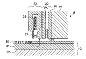
図2は、同実施形態のディスクドライブに使用されるヘッド4及びディスク3の構造を示す。
【0030】
当該ヘッド4は、スライダ21側にリードヘッド22を有し、その後にライトヘッド23を有する。リードヘッド22は、GMR素子24、上部シールドコア25、及び下部シールドコア26を有する。GMR素子24は、それらの一対のシールドコア25,26に挟まれた所定のギャップを形成する空間内に配置されている。
【0031】
ライトヘッド23は、上部磁極(主磁極)27、コイル28、下部磁極(補助磁極)29を有するインダクティブ・単磁極型ヘッドである。主磁極27は、磁極先端が垂直記録方式特有の構造であり、垂直方向の磁束によりディスク3の深さ方向に磁化する。補助磁極29は、主磁極27からディスク3に流入した磁束を引き上げて磁束路を形成する。
【0032】
一方、同実施形態のディスク3は、垂直方向の磁気異方性を示す記録層30と、当該記録層30と基板32との間に軟磁性層31とを有する2層構造ディスクである。軟磁性層31は、主磁極27から発生した磁束を垂直方向に引き込み、記録層30を垂直に磁化するための補助的な役割を果たす。軟磁性層31に流入した磁束は、長手方向に通過し、補助磁極29へ流出する。即ち、主磁極27から発生した磁束は、記録層30、軟磁性層31、及び補助磁極29からなる磁束路を形成する。
【0033】
(記録補償動作)
以下同実施形態の垂直磁気記録での記録補償動作を説明する。
【0034】
まず、図3及び図4を参照して、垂直磁気記録と、外乱磁界によるビットシフト現象を説明する。
【0035】
図4に示すように、回転しているディスク3(回転方向40A)に対して、ライトヘッド(相対的走行方向40B)の主磁極27から、垂直方向の磁束が印加される。この記録動作により、主磁極27のトレーリングエッジ(trailing edge)側のディスク3上には、磁化転移がデータ42として残留する。
【0036】
ここで、垂直方向の外乱磁界41の影響がない場合には、主磁極27からディスク3上に印加される記録磁界(MF)の分布は、実線43に示すようになる。なお、便宜的に、隣接ビットパターンからの記録磁界の影響を無視する。記録磁界が保磁力(Hc)を超える領域で、ディスク3上で磁化反転するため磁化転移位置は点線44となり、ここを正規の磁化反転位置と想定する。
【0037】
一方、ヘッド4が垂直方向の外乱磁界41の影響を受けた場合、主磁極27には、記録電流により発生する磁束と、外乱磁界41による磁束が加算されて、ディスク3に印加される記録磁界(MF)の分布は、点線45に示すようになる。即ち、実線43で示す記録磁界分布に対して、オフセットが生じる。この場合、磁化転移位置46は、正規の磁化反転位置44よりも、ヘッド4の走行方向40Bに対して後方にシフトする。
【0038】
ここで、記録磁界の方向(ディスクの深さ方向)とは、逆となる上向きの外乱磁界の影響を受けた場合には、記録磁界の分布は、実線43に対して下方向(ディスク3の表面側の方向)にシフトし、磁化転移位置は、正規の磁化反転位置44よりも前方に移動する。要するに、外乱磁界が、ライトヘッドの主磁極27による記録磁界を補助する方向(同方向)に働いた場合には、磁化転移位置は正規の位置に対して後方に、また反対方向に働いた場合は前方にシフトする。このような現象が、外乱磁界によるビットシフト現象であり、垂直磁気記録における記録歪みとなる。
【0039】
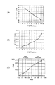
図3(A)は、ライト動作(データ記録)時に、外乱磁界に対するビットシフト量の変化を示す。また、同図(B)は、リード動作(データ再生)での当該外乱磁界に対するエラーレートの関係を示す。これらから、データ記録時の外乱磁界の影響により、ディスク3上の記録ビットシフト量が増加し、これに伴なってデータ再生時のエラーレートが大きく変動していることが確認できる。
【0040】
このようなビットシフトによる記録歪みを解消するための記録補償動作を、図5及び図6を参照して説明する。
【0041】
まず、例えばパーソナルコンピュータであるホストシステム2からライトコマンドが発行されると、CPU12は、HDC10を介して当該コマンドを解読する。ライトチャネル90は、HDC10から当該コマンドに伴なって転送された記録データを受信すると、符号化回路902により所定の符号化データに変換する。
【0042】
図5(A)は、符号化回路902からの符号化データに対応するライト信号の一例を示す。ここでは、ライトヘッドは、ライト信号が論理レベル“H”のときに、ディスク3上に対して深さ方向(下方向)に磁化し、論理レベル“L”のときに表面側方向(上方向)に磁化させる(同図(B)を参照)。なお、図中のTcは、ビット間隔を示し、最短の信号反転間隔に相当する。
【0043】
ここで、前述したように、ライトヘッドの主磁極27が下向きに外乱磁界の影響を受けた場合、図5(B)に示すように、外乱磁界と同方向である下向きの磁化転移B1、B3は、正規の磁化反転位置よりも先行し、逆に上向きの磁化転移B2、B4は後方にシフトする。当該ビットシフト量は、外乱磁界の強度に応じて変化する。なお、便宜的に、隣接ビットパターンによる磁界の影響によるビットシフト量は無視する。
【0044】
同実施形態では、CPU10は、ライトコマンドに従ったデータ記録時に、磁気センサ16からの外乱磁界に関する情報(外乱磁界の磁束方向と強度)に基づいて、フラッシユメモリ13の記録補償テーブル130を参照して、最適な記録補償量を選択して、記録補償回路901に送出する。
【0045】
記録補償回路901では、記録タイミング算出回路901Bは、符号化回路902から得られる記録パターンと、CPU10からの記録補償量とから記録補償するための記録タイミングを求めて、記録信号調整回路901Aに指示する。具体的には、記録タイミング算出回路901Bは、記録磁化の反転方向と外乱磁界の方向との判定処理や、この判定結果(方向の一致又は不一致)による磁化反転の先行または遅延のタイミングの判定処理を実行する。記録タイミング算出回路901Bは、先行または遅延のタイミングの指示と、補償量(ビットシフト量)とを記録信号調整回路901Aに指示する。
【0046】
記録信号調整回路901Aは、記録タイミング算出回路901Bからの記録タイミング調整の指示に従って、図5(C)に示すように、外乱磁界による磁界の方向および強度に合わせて、記録信号の記録タイミングを調整する。ライトアンプ80は、記録信号調整回路901Aにより調整(記録補償)された記録信号をライト電流に変換して、ライトヘッドに供給する。従って、ライトヘッドにより、図5(D)に示すように、正規の位置で磁化反転される記録データを、ディスク3上に垂直磁気記録する。
【0047】
以上のように同実施形態により、CPU12は、磁気センサ16からの外乱磁界の検出結果と、予め用意された記録補償テーブル130とを使用して、外乱磁界の影響により発生する記録歪みを解消するための記録補償をライトチャネル90に対して指示する。ライトチャネル90では、記録補償回路901は、記録信号に対して、外乱磁界の方向と記録磁化の方向とが一致する場合には、正規の磁化反転位置より遅延させる記録タイミングで記録補償を実行する。一方、外乱磁界の方向と記録磁化方向とが不一致の場合には、正規の磁化反転位置より先行させる記録タイミングで記録補償を実行する。この場合、ビットシフト量は、外乱磁界の強度に応じて決定される。
【0048】
従って、垂直磁気記録時に、ライトヘッドに対して外乱磁界の影響がある場合でも、当該外乱磁界に適応する記録補償機能により、結果として正規の位置が磁化転移位置となる垂直磁気記録を実現できる。従って、データ再生時には、記録歪みの影響を抑制できるため、最良のリードエラーレートでのデータ再生を実現できる。
【0049】
(第2の実施形態)
図7は、本発明の第2の実施形態に関するディスクドライブの要部を示すブロック図である。
【0050】
本実施形態は、記録補償機能として、図7に示す記録電流オフセット調整回路70により、ライトアンプ80から出力されるライト電流パターン(記録電流パターン)を調整(オフセット)して、外乱磁界による記録歪みを解消させる補償方法である。具体的には、図4に示す記録磁界分布45を、正規の記録磁界分布43になるように、記録電流パターンをオフセットさせる垂直記録補償機能である。なお、本実施形態に関係する構成要素以外については、図1に示す第1の実施形態の場合と同様であるため、同一符号を付して説明を省略する。
【0051】
まず、本実施形態での記録補償機能の原理は、外乱磁界を打ち消す方向に記録磁界、即ち記録電流パターンをオフセットすることによりビットシフトを解消し、正規の位置での磁化反転を得ることにある。具体的には、前述の図4に示すように、記録磁界と外乱磁界とが同一方向である場合には、外乱磁界が記録磁界を強める方向に作用するため記録歪みが生じる。従って、この場合は記録磁界を弱める、即ち記録電流を低減することにより、ビットシフトを解消することができる。逆に、外乱磁界が記録磁界に対して逆方向に作用し、記録磁界を弱める方向に働く場合には、記録電流を増加することによりビットシフトを解消することができる。また、外乱磁界の強度によって主磁極27の記録磁界分布のオフセット量が変化するため、それに合わせて記録電流のオフセット量を調整する必要がある。
【0052】
以下図7を参照して、具体的に説明する。
【0053】
前述の第1の実施形態と同様に、CPU12は、ライト動作時に、磁気センサ16からの検出情報(外乱磁界の方向と強度)に基づいて、フラッシュメモリ13に予め保存されている記録電流オフセット量テーブルを参照し、記録電流オフセット情報を選択する。記録電流オフセット量テーブルは、ディスクドライブの製造工程時に、所定のテスト装置により、リードエラーレートを指標として最適化された値が算出されてフラッシュメモリ13に格納されている。
【0054】
CPU12は、記録電流オフセット量テーブルから、外乱磁界に適合する記録電流オフセット情報を記録電流オフセット回路70にセットする。記録電流オフセット回路70は、記録電流オフセット情報から、外乱磁界によるビットシフトを解消するために、正負の記録磁化方向に合わせた記録電流値を算出し、ライトアンプ80に与える。ライトアンプ80は、当該記録電流値を受けて、ライトチャネル90からの記録磁化方向と同期させてライトヘッドへ正負で異なる記録電流を印加する。
【0055】
以上のように本実施形態によれば、ライトアンプ80から出力されるライト電流パターン(記録電流パターン)を、外乱磁界に応じて調整して、外乱磁界による記録歪みを解消させる記録補償機能を実現できる。換言すれば、記録磁化方向に応じて記録電流値を可変とするライトアンプ80を使用することにより、ディスク3上の記録データのビットシフト量を調整することができる。ここで、本実施形態の記録補償方法であれば、ライトチャネル90中の記録補償回路は、隣接パターンビットによるビットシフトのみを補償する機能に限定することができる。従って、隣接ビットシフト起因による記録補償は、ライトチャネル90により実行される。これとは区別して、外乱磁界を起因とする記録補償はライトアンプ80により実行されるため、ビットシフト量の調整が容易となる。
【0056】
(変形例)
前述したように、各実施形態では、外乱磁界を検出する磁気センサ16が設けられている。本変形例は、磁気センサ16の代替として、ヘッド4のリードヘッドを構成するGMR素子を利用する構成である。即ち、ライト動作時に、CPU12は、サーボデータに含まれる所定のパターンをGMR素子によりリードして、そのリード信号波形から外乱磁界の強度及び方向を推定する。
【0057】
以下、図8及び図9を参照して具体的に説明する。
【0058】
垂直磁気記録では、ディスク3からGMR素子に流入する磁界が大きいため、外乱磁界の影響が大きい場合には、GMR素子からのリード信号波形には、波形歪を生じる。例えば、外乱磁界がある状態で記録された孤立波形に対応するリード信号波形は、図8(A)に示すように、外乱磁界による出力振幅の変動が招じた波形となる。一方、外乱磁界がない状態でのリード信号波形は、図8(B)に示す波形である。このような出力振幅の変動に基づいて、CPU12は、外乱磁界の強度を推定する。
【0059】
また、CPU12は、サーボデータに含まれる特定パターンに対応するリード信号波形から、外乱磁界の方向を推定する。具体的には、図8(C)に示すような高周波信号とDCの繰り返しパターンのリード信号波形である。ここで、DC部分は、高周波信号部分の干渉の影響を受けない方が感度が高く望ましいが、高周波信号の出力よりDCパターン部の出力が高ければ測定が可能である。また、高周波信号の磁化反転は奇数回であることを特徴としている。本変形例では、NRZI表記でFFFF80パターンが使用されている。
【0060】
さらに、特定パターンの正負方向に、外乱磁界が印加されたときのリード信号波形は、図8(D),(E)に示すような波形となる。図8(D),(E)から明白であるように、低周波部の上下対称性が、外乱磁界の印可方向により逆転していることが分かる。特に、同図(D)は強磁場での外乱磁界の印可が顕著である。に見える。図9(A)は、高周波波形の中央から上向きのDC出力をA、下向きDC出力をBとし、「(A−B)/(A+B)」を指標(アシメントリ:Asym−Dis)とした場合に、外乱磁界と当該指標との関係を示す。この指標により、外乱磁界の強度と方向を特定できる。
【0061】
また、垂直磁気記録では、リード信号波形は矩形波である。このため、リードチャネルの中に微分回路を設けて、リード信号矩形波を微分波形に変換することにより、長手磁気記録方式と同様の信号処理方式を採用できる。この場合、孤立波形のリード信号波形は、長手磁気記録方式と同様の波形となるため、外乱磁界の影響を受けたときの波形歪が、図9(B)に示すように、ピークシフトの変化として現れる。当該ピークシフトは、図9(B)に示すように、外乱磁界と方向との1対1の関係にあるため、外乱磁界の強度と方向の検出に利用することができる。
【0062】
以上要するに、本変形例は、当該特定パターンをディスク3上のサーボエリアに、サーボデータ(サーボパターン)と連続または近傍に記録し、ライト動作時に、リードヘッドであるGMR素子により当該特定パターンを読出す。CPU12は、当該特定パターンに対応するリード信号波形から外乱磁界の強度及び方向を推定する。従って、ディスクドライブの内部には、外乱磁界を検出するための特別の磁気センサ16を設ける必要がない。
【0063】
ここで、ディスクドライブの中には、GMR素子のMR抵抗値をモニタするためのモニタ端子を搭載しているリードアンプ81が設けられたものがある。GMR素子は、ディスク3上の記録磁界により抵抗値が変化すると共に、外部磁界(外乱磁界)の変動によっても変化する。図9(C)は、横軸の外乱磁界と、縦軸のモニタ出力(振幅値)との関係を示す。即ち、モニタ出力(振幅値)は、外乱磁界に対して1対1の関係にあることが明白である。従って、CPU12は、リードヘッドのGMR素子のMR抵抗値をモニタすることにより、外乱磁界を検出することができる。
【0064】
【発明の効果】
以上詳述したように本発明によれば、垂直磁気記録方式のディスクドライブにおいて、ライト動作時に、外乱磁界の検出結果に基づいて、記録データのビットシフトを解消して、記録歪みを補償する垂直記録補償機能を実現できる。従って、外乱磁界に対して有効な記録補償機能を実現することにより、データ再生時のエラーレートを向上させることができる。
【図面の簡単な説明】
【図1】本発明の実施形態に関する垂直磁気記録方式のディスクドライブの要部を示すブロック図。
【図2】同実施形態に関する磁気ヘッドとディスクの構造を説明するための図。
【図3】同実施形態に関する外乱磁界に対するビットシフト量とエラーレートの関係を示す図。
【図4】同実施形態に関する垂直磁気記録とビットシフトを説明するための図。
【図5】同実施形態の記録補償動作を説明するためのタイミングチャート。
【図6】同実施形態に関する記録補償用テーブルと記録補償回路の構成を説明するためのブロック図。
【図7】本発明の第2の実施形態に関するディスクドライブの要部を示すブロック図。
【図8】同実施形態の変形例を説明するための図。
【図9】同実施形態の変形例を説明するための図。
【符号の説明】
1…ディスクドライブ
2…ホストシステム(テスト装置)
3…ディスク
4…磁気ヘッド
5…スピンドルモータ(SPM)6とを有する。
6…アクチュエータ
7…ボイスコイルモータ(VCM)
8…ヘッドアンプ回路
9…リード/ライト(R/W)チャネル
10…ディスクコントローラ(HDC)
11…サーボコントローラ
12…マイクロプロセッサ(CPU)
13…フラッシュメモリ(FROM)
14…RAM
15…ROM
16…磁気センサ
22…リードヘッド
23…ライトヘッド
24…GMR素子
25…上部シールドコア
26…下部シールドコア26
27…上部磁極(主磁極)
28…コイル
29…下部磁極(補助磁極)
30…記録層
31…軟磁性層
32…基板
70…記録電流オフセット回路
80…ライトアンプ
81…リードアンプ
90…ライトチャネル
91…リードチャネル
901…記録補償回路
902…符号化回路(エンコーダ)[0001]
BACKGROUND OF THE INVENTION
The present invention generally relates to a perpendicular magnetic recording type magnetic disk apparatus, and more particularly to a recording compensation technique for compensating for a recording distortion caused by a disturbance magnetic field.
[0002]
[Prior art]
In recent years, in the field of magnetic disk devices typified by hard disk drives (hereinafter sometimes referred to as disk drives), perpendicular magnetic recording systems have attracted attention as a technique for exceeding the limit of recording density in longitudinal magnetic recording systems. Yes.
[0003]
By the way, in the conventional longitudinal magnetic recording type disk drive, in the magnetic recording data recorded on the disk medium, the non-linear bit in which the magnetization transition position (signal inversion position) is shifted forward from the normal position due to the influence of the adjacent bit pattern. A shift occurs. Such a recording distortion phenomenon causes an error rate to deteriorate during data reproduction. For this reason, a recording compensation process for correcting the magnetization transition to a normal position is performed during the write operation. The principle of the recording compensation function is that the bit shift amount depends on the adjacent bit pattern, so that the bit shift amount (including the direction) is predicted and the recording timing is delayed, thereby correcting the magnetization transition to the normal position. .
[0004]
On the other hand, in the perpendicular magnetic recording type disk drive, the magnetization transition position is shifted from the normal position by the adjacent bit pattern. However, unlike the longitudinal magnetic recording system, the recording distortion phenomenon shifts backward. Therefore, in general, in the case of the perpendicular magnetic recording method, a recording compensation function is required in which the recording timing of magnetization transition precedes the normal position.
[0005]
Conventionally, a recording compensation method has been proposed in which a magnetization reversal position based on an adjacent bit pattern is predicted in advance in a recording signal sequence, and the magnetization reversal timing is advanced or delayed in accordance with the adjacent bit pattern (for example, Japanese Patent Laid-Open No. 2000-1990). 207704).
[0006]
[Problems to be solved by the invention]
In recent perpendicular magnetic recording systems, a disk drive using a single pole type head as a write head and a disk having a two-layer structure as a disk medium is being put into practical use. The single magnetic pole head is composed of a main magnetic pole and an auxiliary magnetic pole, and is magnetized in the perpendicular direction (depth direction) of the disk by a recording magnetic field generated in the perpendicular direction from the main magnetic pole. The read head is composed of an MR element (magnetoresistive element) or GMR element (giant magnetoresistive element) similar to the longitudinal magnetic recording method.
[0007]
The two-layer disc has a recording layer exhibiting perpendicular magnetic anisotropy and a soft magnetic layer between the recording layer and the substrate. The soft magnetic layer draws the magnetic flux generated from the main magnetic pole of the write head so that it passes through the recording layer in the vertical direction during the write operation, and further guides the magnetic flux to the auxiliary magnetic pole. It has a function.
[0008]
While this type of drive has high recording efficiency, it is subject to nonlinear bit shifts especially when the recording data on the disk directly under the write head is affected by a magnetic field (disturbance magnetic field) caused by magnetic flux floating outside. There is a high possibility that recording distortion will occur. Such a recording distortion phenomenon cannot be compensated for by the data reproduction processing system, and causes a deterioration in error rate during data reproduction. Therefore, a recording compensation function for such a disturbance magnetic field is required, but the recording compensation method in the prior art as described above cannot cope with a bit shift due to a disturbance magnetic field.
[0009]
Accordingly, an object of the present invention is to realize a recording compensation function effective for a disturbance magnetic field in a perpendicular magnetic recording type disk drive, thereby eliminating recording distortion due to the disturbance magnetic field and reducing an error rate during data reproduction. It is to improve.
[0010]
[Means for Solving the Problems]
According to an aspect of the present invention, in a perpendicular magnetic recording type disk drive, when a disturbance magnetic field is detected during a write operation, a bit of recorded data is determined based on the recording magnetization direction, disturbance magnetic field strength, and disturbance magnetic field direction on the disk. The present invention relates to a perpendicular recording compensation function for canceling shift and compensating for recording distortion.
[0011]
A disk drive according to an aspect of the present invention includes a disk medium capable of magnetic recording of a data signal by a perpendicular magnetic recording method, a magnetic head for performing a data signal write operation and a read operation on the disk medium, and the disk Disturbance detection means for detecting a disturbance magnetic field in the vicinity of the medium; Means for outputting a recording pattern of the data signal perpendicularly recorded on the disk medium during a write operation; Disturbance magnetic field detected by the disturbance detection means during the write operation Information based on, and determined based on the recording pattern On the disk medium Direction of perpendicular magnetic recording And a recording compensation means for executing recording compensation processing Constitution It is.
[0012]
Due to such a configuration, a disturbance magnetic field at the time of write operation is caused when a single magnetic pole type head is used as a write head and applied to a perpendicular magnetic recording type disk drive using a two-layer disk. Recording distortion can be eliminated. Therefore, it is possible to suppress deterioration of the read error rate due to recording distortion during data reproduction for reproducing data recorded on the disc.
[0013]
DETAILED DESCRIPTION OF THE INVENTION
Embodiments of the present invention will be described below with reference to the drawings.
[0014]
(Disk drive configuration)
FIG. 1 is a block diagram showing a main part of a perpendicular magnetic recording type disk drive according to the present embodiment.
[0015]
As shown in FIG. 1, the
[0016]
The
[0017]
The
[0018]
The disk drive further includes a head amplifier circuit (preamplifier circuit) 8, a read / write (R / W)
[0019]
The
[0020]
The read /
[0021]
The
[0022]
The
[0023]
The
[0024]
The
[0025]
Further, the
[0026]
In addition to the
[0027]
(Recording compensation table)
In the embodiment, the
[0028]
The recording compensation table is generated by a predetermined test process by a test apparatus during the manufacturing process of the disk drive. That is, as shown in FIG. 6, the
[0029]
(Head and disk structure)
FIG. 2 shows the structure of the
[0030]
The
[0031]
The write head 23 is an inductive single pole type head having an upper magnetic pole (main magnetic pole) 27, a
[0032]
On the other hand, the
[0033]
(Recording compensation operation)
The recording compensation operation in perpendicular magnetic recording according to the embodiment will be described below.
[0034]
First, with reference to FIG. 3 and FIG. 4, the perpendicular magnetic recording and the bit shift phenomenon due to the disturbance magnetic field will be described.
[0035]
As shown in FIG. 4, a vertical magnetic flux is applied from the main
[0036]
Here, when there is no influence of the disturbance
[0037]
On the other hand, when the
[0038]
Here, when affected by an upward disturbance magnetic field which is opposite to the direction of the recording magnetic field (the depth direction of the disk), the distribution of the recording magnetic field is downward (with respect to the disk 3) The magnetization transition position moves forward relative to the normal
[0039]
FIG. 3A shows the change of the bit shift amount with respect to the disturbance magnetic field during the write operation (data recording). FIG. 5B shows the relationship between the error rate and the disturbance magnetic field in the read operation (data reproduction). From these, it can be confirmed that the recording bit shift amount on the
[0040]
A recording compensation operation for eliminating such recording distortion caused by bit shift will be described with reference to FIGS.
[0041]
First, when a write command is issued from the
[0042]
FIG. 5A shows an example of a write signal corresponding to encoded data from the
[0043]
Here, as described above, when the main
[0044]
In the embodiment, the
[0045]
In the
[0046]
The recording
[0047]
As described above, according to the embodiment, the
[0048]
Therefore, even when there is an influence of a disturbance magnetic field on the write head during the perpendicular magnetic recording, the recording compensation function adapted to the disturbance magnetic field can realize the perpendicular magnetic recording in which the normal position becomes the magnetization transition position as a result. Therefore, when reproducing data, the influence of recording distortion can be suppressed, so that data reproduction at the best read error rate can be realized.
[0049]
(Second Embodiment)
FIG. 7 is a block diagram showing a main part of a disk drive according to the second embodiment of the present invention.
[0050]
In the present embodiment, as a recording compensation function, the recording current offset
[0051]
First, the principle of the recording compensation function in this embodiment is to cancel the bit shift by offsetting the recording magnetic field, that is, the recording current pattern in the direction to cancel the disturbance magnetic field, and to obtain the magnetization reversal at the normal position. . Specifically, as shown in FIG. 4 described above, when the recording magnetic field and the disturbance magnetic field are in the same direction, a recording distortion occurs because the disturbance magnetic field acts in the direction of increasing the recording magnetic field. Therefore, in this case, the bit shift can be eliminated by weakening the recording magnetic field, that is, reducing the recording current. Conversely, when the disturbance magnetic field acts in the direction opposite to the recording magnetic field and works in the direction of weakening the recording magnetic field, the bit shift can be eliminated by increasing the recording current. Further, since the offset amount of the recording magnetic field distribution of the main
[0052]
Hereinafter, a specific description will be given with reference to FIG.
[0053]
Similar to the first embodiment described above, the
[0054]
The
[0055]
As described above, according to the present embodiment, the write current pattern (recording current pattern) output from the
[0056]
(Modification)
As described above, in each embodiment, the
[0057]
Hereinafter, a specific description will be given with reference to FIGS.
[0058]
In perpendicular magnetic recording, since the magnetic field flowing from the
[0059]
Further, the
[0060]
Further, the read signal waveforms when a disturbance magnetic field is applied in the positive and negative directions of the specific pattern are as shown in FIGS. 8D and 8E. As is clear from FIGS. 8D and 8E, it can be seen that the vertical symmetry of the low frequency part is reversed depending on the direction in which the disturbance magnetic field is applied. In particular, in FIG. 4D, application of a disturbance magnetic field with a strong magnetic field is remarkable. Looks like. FIG. 9A shows a case where the upward DC output from the center of the high-frequency waveform is A, the downward DC output is B, and “(A−B) / (A + B)” is an index (asymmetry: Asym-Dis). The relationship between the disturbance magnetic field and the index is shown. With this index, the intensity and direction of the disturbance magnetic field can be specified.
[0061]
In perpendicular magnetic recording, the read signal waveform is a rectangular wave. Therefore, a signal processing method similar to the longitudinal magnetic recording method can be adopted by providing a differentiating circuit in the read channel and converting the read signal rectangular wave into a differential waveform. In this case, since the read signal waveform of the isolated waveform is the same as that of the longitudinal magnetic recording system, the waveform distortion when affected by the disturbance magnetic field changes in the peak shift as shown in FIG. 9B. Appears as Since the peak shift has a one-to-one relationship between the disturbance magnetic field and the direction as shown in FIG. 9B, it can be used to detect the intensity and direction of the disturbance magnetic field.
[0062]
In short, in this modified example, the specific pattern is recorded in the servo area on the
[0063]
Here, some disk drives are provided with a
[0064]
【The invention's effect】
As described above in detail, according to the present invention, in a perpendicular magnetic recording type disk drive, during a write operation, based on the detection result of the disturbance magnetic field, the bit shift of the recording data is eliminated and the recording distortion is compensated. A recording compensation function can be realized. Therefore, by realizing a recording compensation function effective against a disturbance magnetic field, the error rate at the time of data reproduction can be improved.
[Brief description of the drawings]
FIG. 1 is a block diagram showing a main part of a perpendicular magnetic recording type disk drive according to an embodiment of the present invention;
FIG. 2 is a view for explaining the structure of a magnetic head and a disk according to the embodiment.
FIG. 3 is a diagram showing a relationship between a bit shift amount and an error rate with respect to a disturbance magnetic field according to the embodiment.
FIG. 4 is a view for explaining perpendicular magnetic recording and bit shift according to the embodiment;
FIG. 5 is a timing chart for explaining a recording compensation operation according to the embodiment.
FIG. 6 is an exemplary block diagram for explaining the configuration of a recording compensation table and a recording compensation circuit according to the embodiment;
FIG. 7 is a block diagram showing a main part of a disk drive according to a second embodiment of the present invention.
FIG. 8 is a diagram for explaining a modification of the embodiment.
FIG. 9 is a view for explaining a modification of the embodiment.
[Explanation of symbols]
1 ... Disk drive
2 ... Host system (test equipment)
3 Disc
4 ... Magnetic head
5 has a spindle motor (SPM) 6.
6 ... Actuator
7. Voice coil motor (VCM)
8 ... Head amplifier circuit
9: Read / write (R / W) channel
10. Disk controller (HDC)
11 ... Servo controller
12 ... Microprocessor (CPU)
13. Flash memory (FROM)
14 ... RAM
15 ... ROM
16 ... Magnetic sensor
22 Read head
23 ... Light head
24 ... GMR element
25 ... Upper shield core
26 ...
27 ... Upper magnetic pole (main magnetic pole)
28 ... Coil
29 ... Lower magnetic pole (auxiliary magnetic pole)
30 ... Recording layer
31 ... Soft magnetic layer
32 ... Board
70: Recording current offset circuit
80 ... Light amplifier
81 ... Read amplifier
90 ... Light channel
91 ... Read channel
901: Recording compensation circuit
902: Encoding circuit (encoder)
Claims (20)
前記ディスク媒体に対するデータ信号のライト動作及びリード動作を行なうための磁気ヘッドと、
前記ディスク媒体の近傍の外乱磁界を検出する外乱検出手段と、
ライト動作時に、前記ディスク媒体に垂直磁気記録される前記データ信号の記録パターンを出力する手段と、
前記ライト動作時に、前記外乱検出手段により検出された外乱磁界に関する情報、及び前記記録パターンに基づいて判定した前記ディスク媒体上に垂直磁気記録される磁化方向に従って、記録補償処理を実行する記録補償手段と
を具備したことを特徴とする磁気ディスク装置。A disk medium capable of magnetic recording of data signals by perpendicular magnetic recording;
A magnetic head for performing a data signal write operation and a read operation on the disk medium;
Disturbance detection means for detecting a disturbance magnetic field in the vicinity of the disk medium;
Means for outputting a recording pattern of the data signal perpendicularly recorded on the disk medium during a write operation;
During the write operation, the disturbance detecting means information about the disturbance magnetic field detected by, and the following magnetization direction which is perpendicular magnetic recording on said disk medium is determined on the basis of the recording pattern, the recording compensation means for performing a recording compensation process And a magnetic disk device.
前記ディスク媒体上に垂直磁気記録されるデータビット列のビットシフトを補償することを特徴とする請求項1に記載の磁気ディスク装置。The recording compensation means includes
2. The magnetic disk apparatus according to claim 1, wherein a bit shift of a data bit string recorded perpendicularly on the disk medium is compensated.
前記ディスク媒体上に垂直磁気記録されるデータの正規の磁化反転位置に対して、記録磁化タイミングを先行または遅延させることによりビットシフトを補償することを特徴とする請求項2に記載の磁気ディスク装置。The recording compensation means includes
3. The magnetic disk apparatus according to claim 2, wherein a bit shift is compensated by preceding or delaying a recording magnetization timing with respect to a normal magnetization reversal position of data perpendicularly recorded on the disk medium. .
前記外乱磁界の強度と方向、及び前記ディスク媒体上の記録パターンを関係付けた記録補償用テーブルを有し、
当該記録補償用テーブルを参照して、データビット列のビットシフトを補償することを特徴とする請求項1に記載の磁気ディスク装置。The recording compensation means includes
A recording compensation table relating the intensity and direction of the disturbance magnetic field and the recording pattern on the disk medium;
2. The magnetic disk apparatus according to claim 1, wherein a bit shift of the data bit string is compensated with reference to the recording compensation table.
前記記録補償用テーブルを参照して、前記ディスク媒体上に垂直磁気記録されるデータの正規の磁化反転位置に対して、記録磁化タイミングを先行または遅延させることによりビットシフトを補償することを特徴とする請求項4に記載の磁気ディスク装置。The recording compensation means includes
A bit shift is compensated by referring to the recording compensation table by leading or delaying a recording magnetization timing with respect to a normal magnetization reversal position of data perpendicularly recorded on the disk medium. The magnetic disk device according to claim 4.
垂直方向の磁気異方性を示す記録層と、当該記録層と基板の間に設けられた軟磁性層とを有する2層構造から構成されることを特徴とする請求項1に記載の磁気ディスク装置。The disk medium is
2. The magnetic disk according to claim 1, comprising a two-layer structure having a recording layer exhibiting perpendicular magnetic anisotropy and a soft magnetic layer provided between the recording layer and the substrate. apparatus.
当該ライトヘッドは前記ディスク媒体の垂直方向に記録磁界を印加する単磁極式ヘッドから構成されることを特徴とする請求項1に記載の磁気ディスク装置。The magnetic head has a structure in which a write head and a read head are separated from each other.
2. The magnetic disk apparatus according to claim 1, wherein the write head is composed of a single pole type head that applies a recording magnetic field in a direction perpendicular to the disk medium.
垂直方向の磁気異方性を示す記録層と、当該記録層と基板の間に設けられた軟磁性層とを有する2層構造から構成されており、
前記ライトヘッドは、
前記ディスク媒体の垂直方向に磁束を発生する主磁極を有し、かつ、当該主磁極と前記軟磁性層と共に磁束路を構成する補助磁極を有する単磁極式ヘッドから構成されることを特徴とする請求項7に記載の磁気ディスク装置。The disk medium is
It is composed of a two-layer structure having a recording layer exhibiting perpendicular magnetic anisotropy and a soft magnetic layer provided between the recording layer and the substrate,
The light head is
A single magnetic pole type head having a main magnetic pole for generating a magnetic flux in a direction perpendicular to the disk medium and having an auxiliary magnetic pole that forms a magnetic flux path together with the main magnetic pole and the soft magnetic layer. The magnetic disk device according to claim 7.
前記磁気ヘッドに含まれるリードヘッドを構成する磁気抵抗型素子を利用して、当該リードヘッドから出力されるリード信号波形に従って、前記外乱磁界の強度と方向を推定する手段を有することを特徴とする請求項1に記載の磁気ディスク装置。The disturbance detection means includes
The magnetic head has a means for estimating the intensity and direction of the disturbance magnetic field in accordance with a read signal waveform output from the read head using a magnetoresistive element constituting the read head included in the magnetic head. The magnetic disk device according to claim 1.
前記外乱検出手段は、
前記リードヘッドにより当該外乱検出用パターンがリードされたときのリード信号波形に従って、前記外乱磁界の強度と方向を推定する手段を有することを特徴とする請求項9に記載の磁気ディスク装置。A disturbance detection pattern for detecting the disturbance magnetic field is recorded in the servo area on the disk medium,
The disturbance detection means includes
10. The magnetic disk apparatus according to claim 9, further comprising means for estimating the intensity and direction of the disturbance magnetic field in accordance with a read signal waveform when the disturbance detection pattern is read by the read head.
前記外乱磁界の強度と方向を検出する磁気センサを有することを特徴とする請求項1に記載の磁気ディスク装置。The disturbance detection means includes
2. The magnetic disk apparatus according to claim 1, further comprising a magnetic sensor that detects the intensity and direction of the disturbance magnetic field.
前記記録補償手段は、前記外乱検出手段により検出された外乱磁界に関する情報、及び前記ディスク媒体上に垂直磁気記録される磁化方向に従って、当該記録電流パターンにオフセットを与えるような記録補償処理を実行することを特徴とする請求項1に記載の磁気ディスク装置。A write channel that outputs a recording current pattern corresponding to recording data to a write head included in the magnetic head during a write operation;
The recording compensation means executes a recording compensation process that gives an offset to the recording current pattern according to the information on the disturbance magnetic field detected by the disturbance detection means and the magnetization direction perpendicularly recorded on the disk medium. 2. The magnetic disk apparatus according to claim 1, wherein
前記外乱磁界の強度と方向、及び前記ディスク媒体上の記録パターンを関係付けた記録補償用テーブルを有し、
当該記録補償用テーブルを参照して、前記記録電流パターンにオフセットを与えるような記録補償処理を実行することを特徴とする請求項14に記載の磁気ディスク装置。The recording compensation means includes
A recording compensation table relating the intensity and direction of the disturbance magnetic field and the recording pattern on the disk medium;
15. The magnetic disk apparatus according to claim 14, wherein a recording compensation process for giving an offset to the recording current pattern is executed with reference to the recording compensation table.
前記記録補償手段は、前記外乱検出手段により検出された外乱磁界に関する情報、及び前記ディスク媒体上に垂直磁気記録される磁化方向に従って、前記ライトアンプから出力される記録電流値を可変させるような記録補償処理を実行することを特徴とする請求項1に記載の磁気ディスク装置。A write channel that outputs a recording current pattern corresponding to recording data during a write operation, and a write amplifier that supplies a recording current corresponding to the recording current pattern to a write head included in the magnetic head;
The recording compensation unit is configured to change the recording current value output from the write amplifier according to the information on the disturbance magnetic field detected by the disturbance detection unit and the magnetization direction perpendicularly recorded on the disk medium. The magnetic disk apparatus according to claim 1, wherein compensation processing is executed.
前記ディスク媒体の近傍の外乱磁界を検出するステップと、
ライト動作時に、前記ディスク媒体に垂直磁気記録される前記データ信号の記録パターンを出力するステップと、
前記ライト動作時に、前記外乱検出ステップにより検出された外乱磁界に関する情報、及び前記記録パターンに基づいて判定した前記ディスク媒体上に垂直磁気記録される磁化方向に従って、記録補償処理を実行するステップと、
前記記録補償処理ステップにより記録補償された記録パターンに従って、前記磁気ヘッドに含まれるライトヘッドにより前記ディスク媒体上に垂直磁気記録を実行するステップと
を具備したことを特徴とする記録補償方法。A recording compensation method applied to a magnetic disk apparatus having a disk medium capable of magnetically recording a data signal by a perpendicular magnetic recording system and a magnetic head for performing a data signal write operation and a read operation on the disk medium. ,
Detecting a disturbance magnetic field in the vicinity of the disk medium;
Outputting a recording pattern of the data signal that is perpendicularly magnetically recorded on the disk medium during a write operation;
During the write operation, the disturbance detection information about the disturbance magnetic field detected by the step, and in accordance with the magnetization direction is perpendicular magnetic recording on said disk medium is determined on the basis of the recording pattern, and performing a recording compensation process,
And a step of performing perpendicular magnetic recording on the disk medium by a write head included in the magnetic head in accordance with the recording pattern compensated by the recording compensation processing step.
前記記録補償処理ステップは、当該記録補償用テーブルを参照して、前記ディスク媒体上に垂直磁気記録されるデータビット列のビットシフトを補償することを特徴とする請求項17に記載の記録補償方法。A recording compensation table relating the intensity and direction of the disturbance magnetic field and the recording pattern on the disk medium;
18. The recording compensation method according to claim 17, wherein the recording compensation processing step compensates a bit shift of a data bit string perpendicularly recorded on the disk medium with reference to the recording compensation table.
前記記録補償処理ステップは、前記外乱磁界検出ステップにより検出された外乱磁界に関する情報、及び前記ディスク媒体上に垂直磁気記録される磁化方向に従って、当該記録電流パターンにオフセットを与えるような記録補償処理を実行することを特徴とする請求項17に記載の記録補償方法。A write channel that outputs a recording current pattern corresponding to recording data to a write head included in the magnetic head during a write operation;
The recording compensation processing step performs recording compensation processing that gives an offset to the recording current pattern in accordance with information on the disturbance magnetic field detected by the disturbance magnetic field detection step and the magnetization direction perpendicularly recorded on the disk medium. The recording compensation method according to claim 17, wherein the recording compensation method is executed.
Priority Applications (3)
| Application Number | Priority Date | Filing Date | Title |
|---|---|---|---|
| JP2001367848A JP3607672B2 (en) | 2001-11-30 | 2001-11-30 | Magnetic disk apparatus of perpendicular magnetic recording system and recording compensation method applied to the same |
| SG200205277A SG98070A1 (en) | 2001-11-30 | 2002-08-30 | Disk drive including perpendicular magnetic recording system with write compensation |
| US10/234,195 US6873484B2 (en) | 2001-11-30 | 2002-09-05 | Disk drive including perpendicular magnetic recording system with write compensation |
Applications Claiming Priority (1)
| Application Number | Priority Date | Filing Date | Title |
|---|---|---|---|
| JP2001367848A JP3607672B2 (en) | 2001-11-30 | 2001-11-30 | Magnetic disk apparatus of perpendicular magnetic recording system and recording compensation method applied to the same |
Publications (2)
| Publication Number | Publication Date |
|---|---|
| JP2003173503A JP2003173503A (en) | 2003-06-20 |
| JP3607672B2 true JP3607672B2 (en) | 2005-01-05 |
Family
ID=19177535
Family Applications (1)
| Application Number | Title | Priority Date | Filing Date |
|---|---|---|---|
| JP2001367848A Expired - Fee Related JP3607672B2 (en) | 2001-11-30 | 2001-11-30 | Magnetic disk apparatus of perpendicular magnetic recording system and recording compensation method applied to the same |
Country Status (3)
| Country | Link |
|---|---|
| US (1) | US6873484B2 (en) |
| JP (1) | JP3607672B2 (en) |
| SG (1) | SG98070A1 (en) |
Families Citing this family (4)
| Publication number | Priority date | Publication date | Assignee | Title |
|---|---|---|---|---|
| US7126773B1 (en) * | 2005-03-30 | 2006-10-24 | Hitachi Global Storage Technologies Netherlands, B.V. | Write precompensation method for perpendicular magnetic recording |
| US7538963B2 (en) * | 2006-03-27 | 2009-05-26 | Hitachi Global Storage Technologies Netherlands B.V. | System, method, and apparatus for monitoring stray magnetic fields and protecting disk drives therefrom |
| JP2008041159A (en) * | 2006-08-04 | 2008-02-21 | Hitachi Global Storage Technologies Netherlands Bv | Magnetic disk unit |
| US8654471B2 (en) | 2011-09-30 | 2014-02-18 | Lsi Corporation | Disk-based storage device having write signal compensation for magnetization polarity of adjacent bits |
Family Cites Families (5)
| Publication number | Priority date | Publication date | Assignee | Title |
|---|---|---|---|---|
| JPH0344809A (en) * | 1989-07-13 | 1991-02-26 | Fujitsu Ltd | Thin-film magnetic head for perpendicular recording |
| US5187622A (en) * | 1990-08-20 | 1993-02-16 | Teac Corporation | Magnetic disk drive apparatus having a protection mechanism for protecting a magnetic head from collision with a magnetic disk when loading or unloading the magnetic disk |
| US5724336A (en) * | 1995-04-25 | 1998-03-03 | Morton; Steven G. | Tera-byte disk drive |
| JP2000207704A (en) | 1999-01-14 | 2000-07-28 | Hitachi Ltd | Signal processing device and digital signal recorder sharable between in-plane and perpendicular recording media |
| JP4198873B2 (en) * | 2000-09-21 | 2008-12-17 | 株式会社東芝 | Perpendicular magnetic recording type magnetic disk drive |
-
2001
- 2001-11-30 JP JP2001367848A patent/JP3607672B2/en not_active Expired - Fee Related
-
2002
- 2002-08-30 SG SG200205277A patent/SG98070A1/en unknown
- 2002-09-05 US US10/234,195 patent/US6873484B2/en not_active Expired - Fee Related
Also Published As
| Publication number | Publication date |
|---|---|
| SG98070A1 (en) | 2003-08-20 |
| US20030103290A1 (en) | 2003-06-05 |
| US6873484B2 (en) | 2005-03-29 |
| JP2003173503A (en) | 2003-06-20 |
Similar Documents
| Publication | Publication Date | Title |
|---|---|---|
| JP4112809B2 (en) | Magnetic disk apparatus of perpendicular magnetic recording system and disk manufacturing method | |
| JP5808273B2 (en) | Magnetic head, head drive control device, magnetic storage device, and control method thereof | |
| US7701657B2 (en) | High-density recording method for hard disk drives and a pre-amplifier circuit suitable for use with same | |
| CN100533553C (en) | Magnetic disk drive | |
| US5963385A (en) | Magnetic recording/reproducing apparatus and method for supplying a current to a magnetic head to stabilize a magnetized state of a magnet pole | |
| US20130258514A1 (en) | Microwave-assisted magnetic recording device and method using non-constant microwave | |
| JP2007172751A (en) | Disk apparatus and control method of disk apparatus | |
| JP3607672B2 (en) | Magnetic disk apparatus of perpendicular magnetic recording system and recording compensation method applied to the same | |
| JP4028201B2 (en) | Perpendicular magnetic recording type magnetic disk drive | |
| JP2010123233A (en) | Magnetic disk drive and method for recording data to magnetic disk | |
| JP4044922B2 (en) | Magnetic recording head | |
| US20020089773A1 (en) | Disk drive including preamplifier for perpendicular magnetic recording system | |
| Hwang et al. | Generalized interlaced magnetic recording with flexible inter-track interference cancellation | |
| US6894855B2 (en) | Magnetic disk drive including read channel for processing differentiated read signal | |
| US20040151036A1 (en) | Magnetic head for performing perpendicular magnetic recording in a disk drive | |
| US6903890B2 (en) | Method and apparatus for write compensation of perpendicular magnetic recording in disk drive | |
| JP3349392B2 (en) | Storage device | |
| JP2003045133A (en) | Vertical magnetic recording type servo writing method and magnetic disk unit | |
| JP2004103132A (en) | Recording/reproducing device and method, recording medium, and program | |
| JP3325403B2 (en) | Magnetic disk drive | |
| JP2004005839A (en) | Magnetic disk drive | |
| JP2002197603A (en) | Magnetic disk device and head amplifier circuit | |
| JP2013004153A (en) | Magnetic information recorder and magnetic information recording method | |
| JP2002170202A (en) | Storage device | |
| JP2002251703A (en) | Magnetic recorder |
Legal Events
| Date | Code | Title | Description |
|---|---|---|---|
| A131 | Notification of reasons for refusal |
Free format text: JAPANESE INTERMEDIATE CODE: A131 Effective date: 20040203 |
|
| A521 | Request for written amendment filed |
Free format text: JAPANESE INTERMEDIATE CODE: A523 Effective date: 20040326 |
|
| TRDD | Decision of grant or rejection written | ||
| A01 | Written decision to grant a patent or to grant a registration (utility model) |
Free format text: JAPANESE INTERMEDIATE CODE: A01 Effective date: 20041005 |
|
| A61 | First payment of annual fees (during grant procedure) |
Free format text: JAPANESE INTERMEDIATE CODE: A61 Effective date: 20041007 |
|
| FPAY | Renewal fee payment (event date is renewal date of database) |
Free format text: PAYMENT UNTIL: 20081015 Year of fee payment: 4 |
|
| FPAY | Renewal fee payment (event date is renewal date of database) |
Free format text: PAYMENT UNTIL: 20081015 Year of fee payment: 4 |
|
| FPAY | Renewal fee payment (event date is renewal date of database) |
Free format text: PAYMENT UNTIL: 20091015 Year of fee payment: 5 |
|
| FPAY | Renewal fee payment (event date is renewal date of database) |
Free format text: PAYMENT UNTIL: 20101015 Year of fee payment: 6 |
|
| LAPS | Cancellation because of no payment of annual fees |