【0001】
【発明の属する技術分野】
この発明は軸方向の空洞を有した三角、四角、多角、異形、円形などの各種の断面形状の素型材の一部もしくは全体の表面に彫り込みの深い任意の形態の凹凸加工を高い精度でかつ効率良く形成する直線駆動式成形転造装置に関するものであり、一例を挙げると、自動車のステアリング部品であるラックバーの製造に応用することができるが、この発明はラックバーの製造に限らず各種の機械機能部品や装飾部品に所望の表面凹凸形状ないしは模様を付すのに応用することができるものである。
【0002】
【従来の技術】
自動車のステアリング部品であるラックバーを中空素型材から転造により成形する技術は原理的には公知である。即ち、ラックバーの転造成形においては、まず、加熱によって軟化された中空素型材を型によって保持しつつプレスをかけることにより中空棒のラック形成面の平坦化が行われる。次に、内周に直線方向の歯列を有した成形型を中空棒の前記平坦部に当てつつ外側より中空棒の空洞に芯金が圧入される。芯金はテーパ状の作用部を有しており、テーパ部が平坦部に内周側において係合することにより平坦部の肉は成形型に向けて塑性変形的に流動することにより張り出され、平坦部に成形型の歯列に順じた形状の直線方向の歯列が付与される。心金の一回の圧入のみでは所期の精度の製品は得られないため、作用径が順次変化した心金をタレット型に配置し、心金の作用径を順次変更しながら加工を行うことが提案されている。
【0003】
【発明が解決しようとする課題】
タレット型のものでは一つの割型毎に作用径の変化するタレットが必要であり、一回の圧入操作によって得られる製品は一個のみであり、生産効率としては極度に悪化してしまい、鍛造によるラックバー製造のメリットは殆ど生かせないためタレット型のものはこれまで実用には殆ど供されていなかった。
この発明はこの問題点に鑑みてなされたものであり、タレット型の欠点を解消し、複数の心金の一斉圧入を可能とすることにより複数製品の同時製造を実現するとともに精度的にも切削品と遜色がなく、しかもコスト的にも安価に押えうるようにすることを目的とする。
【0004】
請求項1に記載の発明によれば、横方向に重ねて配置される横割の複数の割型と、割型を載置するためのベッドと、横方向に重ねて配置される割型に対しその両側から挟むように加圧することにより複数の直線状の異形断面の素型材をそれぞれの割型に加圧保持せしめる加圧手段と、複数の芯金を横方向に平行に離間して保持する芯金ホルダと、芯金ホルダにより保持された複数の芯金を各割型に保持されたそれぞれの素型材の軸方向の空洞に向けて一斉に圧入するための芯金圧入手段とを備え、素型材への芯金の圧入による素型材の外周への金型内周の凹凸に準じた形状の形成が複数の素型材について一挙に行われることを特徴とする直線駆動式成形転造装置が提供される。
【0005】
請求項1の発明の作用・効果を説明すると、横方向分割の割型は複数が横重ねに配置され、そして横重ねの割型に両側から加圧手段による加圧力が加えれ、そして、各素型材をそれぞれの割型によりクランプした状態でホルダにより保持された複数の芯金が夫々の素型材の空洞への一斉に圧入され、各素型材の転造が同時に行われる。このとき、芯金圧入によって割型よりベッドに加わる転倒モーメントは割型が一つの場合と同様となる。割型を縦割りとしこれを横並びとして上下に一斉にクランプしようとする場合、クランプ力が巨大となるし、個々の割型を別個にクランプ使用とすると割型のセット数に一致した加圧手段が必要となるが、この発明では横割の割型を横重ねにして横方向の両側からクランプすることで、クランプ力を少しも増大させることなく加圧手段を一個で済ませることができ、コスト的に極めて有利な効果を得ることができる。
【0006】
請求項2に記載の発明によれば、横並びで配置された複数の割型と、各割型を型合わせ方向に加圧することにより直線状の異形断面の素型材をそれぞれ保持せしめる加圧手段と、平行に離間した複数の芯金ホルダを複数工程順に従って積み重ね状に保持するためのスタッカと、スタッカに積み重ね状に保持された芯金ホルダのうちの任意の一つのホルダをスタッカから取り出すとともに使用済みのホルダを芯金ホルダに返却する手段と、その一つの芯金ホルダにより保持され芯金を対応の割型に保持された素型材の軸方向の空洞に向けて一斉に圧入しかつ引き戻すための芯金圧入・引戻手段とを備え、スタッカに積み重ねられた複数の芯金ホルダより一づつ芯金ホルダを工程順に従ってスタッカから取り出し、各素型材への芯金の圧入が異なった芯金により多段階に行われることを特徴とする直線駆動式成形転造装置が提供される。
【0007】
請求項2の発明の作用・効果を説明すると、芯金ホルダにはその加工段の芯金が数本まとめてなるべくはワンタッチで着脱自在に保持され、各加工段の芯金ホルダは加工順序に従ってスタッカに積み重ね状にセットされる。スタッカより加工順序に準じて芯金ホルダが取り出され、芯金ホルダに保持された芯金は横並びの割型にクランプされた対応の素型材に一斉に圧入され、圧入工程の終了後に芯金は引き抜かれ、数回の圧入・引き戻しの繰り返し後に、芯金は芯金ホルダともどもスタッカに再収納され、スタッカのシフトなどの操作により次の加工順の芯金を保持した芯金ホルダがスタッカより取り出され、以下同様に芯金の圧入−引引き戻しスタッカへの収納−次の段階の芯金ホルダの取り出しが繰り返される。この構成により多段階的な転造操作を極めて効率的に実施できる効果がある。
【0008】
請求項3に記載の発明によれば、請求項1若しくは2に記載の発明において、金型の上方に外部に開放した空間が形成され、該空間に金型への素材の装入及び製品の搬出のためのローダーが設置されることを特徴とする直線駆動式成形転造装置が提供される。
【0009】
請求項3の発明の作用・効果を説明すると、ローダーにより開放した金型の上方から素材の装入、製品の搬出ができるため、空間の有効活用が実現され、装置全体をコンパクトにできる。
【0010】
請求項4に記載の発明によれば、請求項3に記載の発明において、スタッカは割型の両側に設置され、スタッカに積み重ねられた複数の芯金ホルダより一つづつ芯金ホルダを工程順に従って両側のスタッカより交互に取り出し、各素型材への芯金の圧入が異なった芯金により多段階に行われることを特徴とする直線駆動式成形転造装置が提供される。
【0011】
請求項4の発明の作用・効果を説明すると、左右のスタッカから芯金ホルダを工程順に従って順次取り出し、取り出された芯金ホルダの芯金を左右交互に圧入しているため、薄肉管表面への深い凹凸模様の転造を精度高く実施することができる効果がある。
【0012】
請求項5の発明によれば、請求項4に記載の発明において、一方の側のスタッカからの芯金ホルダにおける芯金のための往復駆動機構と反対側のスタッカからの芯金ホルダにおける芯金の往復駆動機構とは独立のタイミングにて駆動されることを特徴とする直線駆動式成形転造装置が提供される。
【0013】
請求項5の発明の作用・効果を説明すると、左右独立の駆動タイミングの選定は多品種少量生産システムに対する適合性を高め、一台の機械により異なった製品を段取り変えなしに又は最小の段落変えで生産することを実現できる。
【0014】
請求項6に記載の発明によれば、割型と、割型を型合わせ方向に加圧することにより直線状の異形断面の素型材を保持せしめる加圧手段と、芯金を割型に保持された素型材の軸方向の空洞に向けて圧入しかつ引き戻すための油圧シリンダ手段とを備え、該油圧シリンダ手段は撓み角度相殺用の逆撓みリブに取り付けられることを特徴とする直線駆動式成形転造装置が提供される。
【0015】
請求項6の発明の作用・効果を説明すると、この発明の実施において、割型のクランプ方向と芯金の圧入方向がX,Yの十字状に直交する配置となり易い。この十字配置の場合X軸の加圧手段もY軸の加圧手段も中間に支柱を設けることが作業性の維持のため困難であり、片持ち支持となる。この場合構造的に応力歪による突出顎部の開口が発生し、加圧軸心にずれが生じ易い。このずれは芯金の寿命を短くするおそれがある。これに対し第7の発明においては、加圧装置の顎部に直接シリンダを設けず、撓み角度相殺用の逆撓みリブを追加しこれにシリンダを設けることにより、顎部とリブとの間に相互に反対方向の歪が生じ、歪を打ち消しまたは小さくすることができ、軸心のずれを防止又は最小とすることができる。
【0016】
【発明の実施の形態】
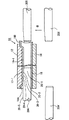
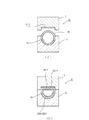
図1及び図2はこの発明の一実施形態としての金属円管からの車両のステアリング部品である中空ラックの転造形成を概略的に示すものである。割型としての金型10は上型12と下型14とから構成され、図2と金型10の断面を(イ)において開放状態、(ロ)において閉鎖状態にて示す。上型12は下型14に面したその内周面における長さ方向凹部にラック歯状の歯部12−1を有しており、一方、下型14は上型12に面した上面に断面半円弧状の長さ方向溝14−1を形成している。図2の(イ)では下型14の断面半円弧状長さ方向溝14−1に円管18がすでに載置された状態を示している。
【0017】
図2の(イ)の状態から上型12と下型14とを相互に向き合う方向に移動させることにより図2の(ロ)のように金型10を閉鎖すると、円管18は上型12に面する上半分18−1が平坦に潰され、ラック歯の成形転造を受けるべき異形の素型材となる。図1は図2の(ロ)に示す閉鎖状態における金型10の長さ方向断面図を示す。金型10は円形断面の素材管18の約1/2以下の長さしかない。そして、円管18の一端は金型10と面壱であるが、反対端は1/2の長さ以上突出している。しかしながら、下型14に面した上型12の下面に形成される歯部12−1は金型10の端面から幾分手前に留まっており、従って、金型10の閉鎖状態において素材管18の左端18A及び右端18Bは平坦に圧潰されておらず、換言すれば素材管18の両端18A, 18Bは円形断面のままに留まっている。
【0018】
図1及び図2に説明したこの発明の実施形態では素材管18のラック形成面である上面の平坦化=異形素型材の形成をラック転造形成用金型10の閉鎖即ち上型12と下型14との合体によって行っている。即ち、上型12のラック状歯部12−1は金型閉鎖時は下型14の底面からの距離が素材管18の外径の半分強のところに来るため素材管18は上型12のラック状歯部12−1によって図2の(ロ)に示すように平坦に潰されるのである。そのため、金型10は型開きすることなくそのまま連続して次の工程に順次移行することができる。これにより、工程をラップ化できると共に、クランプ動作を最初の1回のみにすることができるためクランプによる傷の発生の機会をなくすることができる利点がある。また、転造用の型を異形化のために使用していることから異形化の精度は異形化専用の本来の型を使用した場合と比較して低下があるが、要求精度がよほど高くない限りは実際上の問題はないことがわかった。平坦化のため専用の型により円管の上面を潰し、その後型開きし、転造用の金型にクランプするような通常の工程をとることももとより可能である。
【0019】
図1において、割型12, 14間に保持された断面平坦化後の素材管18は芯金の圧入・引き戻しによるこの発明の転造工程を受ける。以下、これについて説明すると、芯金20A, 20Bは金型10にクランプされることにより上面が平坦化されたた素材管18の両側に軸方向に対向して配置される。芯金20A, 20Bはその断面形状は図2の(ロ)に示すように断面平坦化された素材管18の部分の断面形状に順じた断面形状を有している。図1に示すように芯金20A, 20Bの先端は案内部20−1をなしており、断面平坦化された素材管18の部分への導入のガイドとなる。案内部20−1の背後にはテーパ部20−2を経由して拡径部20−3が継続し、芯金20A, 20Bの圧入時にテーパ部20−2は素材管18の平坦部18−1に係合することにより素材管の肉を内から外に金型のラック歯状部12−1の凹凸に向けて金属流動させ、素材管の平坦部18−1にその凹凸形状に相補的なラック状歯部が賦型される。図1では芯金20A, 20Bは第1の拡径部20−3に後続してテーパ部20−4を介して第2の拡径部20−5が続いており、一本の芯金による順次の多段階の金属流動が得られるようになっている。
【0020】
図1においては第1の工程として左側の芯金20Aが平坦化されたばかりの素材管18に圧入された最初の状態を示している。左側の芯金20Aの圧入は素材管の平坦部18−1の右端に最後の拡径部20−5が到達するまで行われ、その後芯金20Aは素材管18から完全に抜去される至るまで左側に向けて移動される。
【0021】
左側の芯金20Aの抜去と適切なラッピングのタイミング差をもって右側の芯金20Bは図1の左側への移動を開始し、右側の芯金20Bが素材管18の内部空洞に導入されるに至り、その拡径部により左側の芯金20Aについて説明したものと同様な金属流動の過程が惹起される。
【0022】
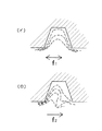
右側芯金20Aの圧入−抜去及びこれに継続する左側芯金20Bの圧入−抜去は数回繰り返される。即ち、素材管18に対する左右の芯金20A, 20Bの圧入が交互に複数回繰り返される。素材管18の内部空洞に対する各芯金20A, 20Bの繰り返し的な圧入は金型の凹部に対する肉の確実な流動を促すことができる。即ち、芯金の一回の圧入のみでは肉の流れが不充分であり、精度の高い転造が行いえない恐れがあるが、繰り返し的な圧入によりこのようなおそれを回避することができる。また、左右の芯金20A, 20Bの複数回の交互圧入により金型の凹部に対する均等な金属流動を得ることができ、精度の高い転造を実現できる効果がある。即ち、図3は転造により得られた実際のラックの歯部の断面顕微鏡写真における歯部の層形成状態から把握された肉の流動状態を模式的に表したものである。矢印f1に示すような交互圧入を行うこの発明の肉の流動状態は(イ)にて表され対称的な流動状態が得られていることが分かる。一方、(ロ)は芯金の圧入方向が矢印f2のような一方のみである場合の流動状態を示しており、この場合は肉の流動に片寄りがあり、また巻き込みが発生していることが分かる。このような肉の不均一な流動状態は、ラック歯の成形完了後における不均一な応力残留及びこれに伴う弾性歪の戻り即ちスプリングバック量の不均一を惹起せしめ、製品の精度低下の原因となるがこの発明においては均等な肉の流動が確保されるためこのような問題点は解消されている。
【0023】
再び図1において、芯金の上下方向のシフトについて説明すると、左右の芯金20A, 20Bからなる対は上下に複数設けられている。図1には芯金20A, 20Bの対の下方にもう一つの芯金20A’, 20B’の対が示されているが必要な段数の芯金対が上下方向に配置されている。シフトの毎に加工が段階を追って進むようにシフト方向で作用径などの芯金の形状が漸次変化されている。複数段の芯金対は図1には示されない左右のスタッカに積載されており、スタッカをシフトしながら加工が行われるようになっている。即ち、最初の加工段の芯金20A, 20Bを交互に圧入することにより第1段の加工を行った後、左右のスタッカにおける芯金ホルダは待機時に矢印aのように上方向にシフトされ、第2段目の芯金20A’, 20B’が素材管18に整列せしめられ、芯金20A’, 20B’は交互に素材管18の内部空洞に圧入せしめられ、第2段階の加工が実施され、以下同様に必要段数の加工が実施される。このように芯金を少しづつ変化させて加工を多数段にわたって行うことにより肉薄の素材管に対しても深い凹凸形状の賦型を精度高く実現することができる効果がある。
【0024】
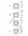
図4の(イ)〜(ニ)はこの発明を実施しうる各種の異形素型材及びそれに凹凸形状を賦与するための金型の割り構造を説明している。図4の(イ)は図1及び2に関連して説明した円管の上半分を平坦化した素材18Aを示す。金型は上型12Aと下型14Aとからなり、上型12Aは素材18Aの平坦部に面して凹凸部12A−1を有しており、芯金の圧入により素材18Aの平坦面にこの凹凸に相補的な凹凸形状が形成される。
【0025】
図4の(ロ)は矩形断面の素材18Bを示しており、素材18Bは上型12Bと下型14Bとの間にクランプされる。上型12Bは素材18Bの一側面に面して凹凸部12B−1を有しており、芯金の圧入によりこの凹凸に相補的な凹凸が素材18Bの一側面に形成される。
【0026】
図4の(ハ)は6角形断面の素材管18Cを示しており、金型は12C, 12C’, 14Cからなる三つ割にされ、各割型12C, 12C’, 14Cの内面に凹凸12C−1, 12C’−1, 14C−1が形成され、芯金の圧入によりこの凹凸に相補的な凹凸を6角断面素材管18Bの一つおきの側面に形成することができる。
【0027】
図4の(ニ)は3角形断面の素材管18Dを示しており、金型は上型12Dと下型14Dとから構成され、上型12Dの内面に凹凸12D−1が形成され、芯金の圧入によりこの凹凸に相補的な凹凸を3角断面素材管18Dの上面に形成することができる。
【0028】
図5は素材管の平坦表面12A−1, 12B−1, 12C−1, 12D−1に付される凹凸形状の各種のバリエーションを例示しており、Iは山歯列、IIは凹凸キー、IIIは凹凸の卍模様を示しており、その他この発明の実施により各種の凹凸形状ないしは模様を素材管の表面に付することができる。
【0029】
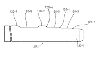
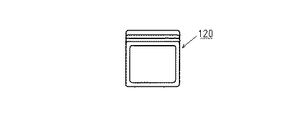
図6及び図7は図4(ロ)の実施形態において使用しうる矩形断面を有した芯金のより具体的な構造を示している。芯金120は先端の案内部120−1と、案内部120−1に後続する第1のテーパ部120−2と、第1のテーパ部120−2 に後続する第1の拡径部120−3と、第1の拡径部120−3に後続するテーパ部120−4と、第2のテーパ部120−4に後続する第2の拡径部120−5と、第2の拡径部120−5に後続する第3のテーパ部120−6と、第3のテーパ部120−6に後続する第3の拡径部120−7と、第3の拡径部120−7に後続する縮径部120−8と、縮径部120−8に後続しホルダの根元近くまで延びる座屈防止当たり部120−9とからなる。
【0030】
素材管への芯金120の圧入時に案内部120−2より芯金は素材管に導入され、第1のテーパ部120−2を介して第1の拡径部120−3が素材管の内周に係合することにより金型内周の凹凸部への素材の肉の流動が惹起される。圧入がさらに進行するとテーパ部120−4, 120−6及び拡径部120−5, 120−7により同様な素材の金属流動が惹起される。拡径部120−3, 120−5, 120−7は拡張作動中において素材の圧縮強さの数倍の単位面圧を受けることから芯金の素材は燐酸塩処理を受けたものであることが好ましい。また、作動中の油膜切れに対処するため拡径部120−3, 120−5, 120−7はその表面にオイルポットとなりうる極小のラビリンス溝や微小梨地模様など形成処理を施しておくのが好適である。このようなオイルポットは成形部だけでなく成形時に反力を受ける対抗側の面に設けることが好ましい。又は、オイルポットは成形部の全周に設けてもよい。
【0031】
図6では段階的に径が増大するテーパ部120−2, 120−4, 120−6及び拡径部120−3, 120−5, 120−7を設けることにより一回の圧入における肉の流動が順次行われ、トータルとしての肉の流動量を多くすることができ、生産性を高めることができる。この場合に潤滑油の封じ込めが強くなり転造による造形形状を狂わせるおそれがある。拡径部120−7の背後に設けられる縮径部120−8は封じ込められた潤滑油を逃すことによりこれを防止する機能を達成する。
【0032】
芯金の圧入を継続してゆくと当たり部120−9は素材管の内周に密に嵌り込み、芯金に加わる座屈方向の荷重を受ける機能を達成する。即ち、素材管への芯金の圧入がある深さ以上になり拡径部120−3, 120−5, 120−7を過ぎた芯金の根元側では当たり部120−9が素材管に僅かの隙間にて嵌合した状態で先端側での転造が進められる。そのため、長いラックバーの転造形成の場合においても当たり部120−9 により素材の安定支持が行なわれ、座屈限界に余裕を持たせることができ一回の圧入時の金属流動量を多くした場合における芯金の必要な耐久性の確保を図ることができる。
【0033】
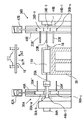
次に、図8及び図9によってこの発明の原理による転造形成の実施としての複数本芯金同時圧入及び多段シフト方式のラックバー転造装置を説明する。図8及び図9において、30はその上に金型を載置するためのベッドであり、横開きの割型としての複数(図では3個)の金型110が横方向に重ねて配置される。各金型110は二つの割型112, 114より構成され、一方の割型112は図2と同様にラック歯状の凹凸を有しており、他方の割型114は円管状の素材を収容するための半円形溝を形成している。
【0034】
ベッド30上における金型110の並び方向における一側に加圧シリンダ32が設けられ他側に受圧枠34が配置される。加圧シリンダ32はピストン32−1を備え、ピストン32−1が引き戻された状態では図8の上半分(一点鎖線Lから上)に示すように各金型110はそれを構成する横割の割型112, 114が分離され(図2の(イ)も参照)、その間に素材管を挿入するための空間Sを形成することができる。油圧の供給によって加圧シリンダ32のピストン32−1が図8の下半分に示すように加圧のために前進されると、割型112, 114はベッド30上を横方向に移動され、横重ねされた金型110はピストン32−1と受圧枠34との間に挟着保持され、各金型110を構成する割型112, 114は図2の(ロ)に示すと同様に合体され図8の下半分に示すように割型112, 114の間に素材管18(破線にて示す)がクランプされる。
【0035】
金型110の横重ね方向と直交する方向の両側において、即ち、割型112, 114によりクランプされた素材管18の軸線方向の両端側にスタッカ36A, 36Bが配置される。図9に示すように左側のスタッカ36Aは上下方向に多段に配置された芯金ホルダ38A−a, 38A−b, 38A−c(図示では芯金ホルダの個数は3であるがそれ以外の任意の必要な数の芯金ホルダを具備させることができる)と、これら芯金ホルダ38A−a, 38A−b, 38A−c を上下摺動自在状態に保持するスタッカ枠40Aと、スタッカ枠40A内での芯金ホルダ38A−a, 38A−b, 38A−cの上下動を行わしめる昇降機構42Aとから構成される。芯金ホルダ38A−a, 38A−b, 38A−cの各々は所定本数の芯金20Aをワンタッチ式に着脱可能な構造となっている。また、左側芯金ホルダスタッカ36Aの外側には圧入制御用油圧シリンダ44Aが設けられ、圧入制御油圧シリンダ44Aのピストン44A−1はスタッカ36Aに保持される芯金ホルダ38A−a, 38A−b, 38A−cに順次係合され、選択された芯金ホルダを図の右から左に移動させ、その芯金ホルダに保持された芯金を金型にクランプされた素材管18の内部空洞に向けて圧入し、図1で説明したように素材管の外面に金型内周に形成される凹凸に順じた形状の凹凸を付与する。
【0036】
一つの芯金ホルダ38A−aに保持された複数本の芯金20Aによる圧入が終わると、芯金ホルダ38A−aはスタッカ枠40Aの部位まで左方向に後退され、昇降機構42Aによってスタッカ枠40A内の芯金ホルダは上下方向(例えば上方向)に一段シフトされ、ピストン44A−1により次の加工順の芯金ホルダ38A−cが図9の右方向に押し出され、芯金ホルダ38A−cに保持された芯金20A’は素材管18の軸方向内部空洞に圧入され、次の段階の転造操作が実施される。
【0037】
図9において金型ベッド30の右側に配置されたスタッカ36Bの構造は左側のそれと同様であり、上下方向に多段に配置された芯金ホルダ38B−a, 38B−b, 38B−cと、芯金ホルダ38B−a, 38B−b, 38B−c を上下摺動自在に保持するスタッカ枠40Bと、スタッカ枠40B内での芯金ホルダ38B−a, 38B−b, 38B−cの昇降を行わしめる昇降機構42Bとから構成される。また、右側芯金ホルダスタッカ36Bの外側には圧入制御用油圧シリンダ44Bが設けられ、圧入制御油圧シリンダ44Bのピストン44B−1はスタッカ36Bに保持される芯金ホルダ38B−a, 38B−b, 38B−cに順次係合され、選択された芯金ホルダを図の右から左に移動させ、芯金ホルダに保持された芯金を金型110にクランプされた素材管18の内部空洞に向けて圧入し、図1で説明したように素材管の外面に金型内周に形成される凹凸に順じた形状の凹凸を付与する。また、昇降機構42Bによってスタッカ枠40B内の芯金ホルダは上下方向に一段づつシフトされる。
【0038】
圧入段階の進行に応じて左右の芯金ホルダのシフトは連動的に行われるが、かつ各段階において左右の芯金は図1に関連して説明したように交互に素材管18に圧入される。即ち、図9においては第2段階の転造操作が実施されており、左側の芯金ホルダ38A−bに保持された芯金20Aが圧入シリンダのピストン44A−1により右方向に移動された芯金20Aは横重ねの各金型110にクランプされたそれぞれの素材管18に一斉に圧入され、その圧入が終わると芯金ホルダ38A−bに保持された芯金20Aは左側に引き戻され、その引き戻しとラップさせて右側の第2段目の芯金ホルダ38B−bに保持された芯金20Bが圧入シリンダ44Bのピストン44B−1により図9の左方向に移動され、芯金20Bは横重ねの金型110にクランプされたそれぞれの素材管18に一斉に圧入される。そして、このような芯金ホルダ38A−b, 38B−bの左右の圧入は図1に関連して説明したと同様に複数回繰り返して実施される。この段の転造操作が完了すると、左側のスタッカ及び右側のスタッカのシフトが所定方向、例えば上方向に実施され、次の段のための芯金ホルダ38A−c, 38B−cに保持された芯金20A’, 20B’が複数本同時に左右に交互に素材管に圧入され、この段階の転造操作が実施される。
【0039】
図8及び10の転造方式においては、それぞれが横割の複数の金型110が横重ねされ両側から加圧することにより各金型を構成する割型112, 114を合体保持するようにしている。金型に保持された素材管へ芯金を圧入した場合に金型が芯金圧入力によってベッド30上で受ける転倒モーメントMはベッドから金型の中心までの距離Lに加圧力Pを掛けたものであり、M=L×Pとなるが、複数の金型を横重ねとしているため、転倒モーメントの値は金型が一つの場合と全く同一となる利点がある。
【0040】
また、芯金圧入時の金型110を閉鎖状態に保持する油圧シリンダ32による加圧力については複数の金型を加圧方向(横方向)に重ねた場合の保持力は近接金型間の反力の打ち消しにより、一個の金型を保持する加圧力と同一であり、複数金型のため油圧シリンダ32として大型のものを採用する必要はない。
【0041】
この発明の実施形態においては、心金20A, 20Bの移動方向と金型110の移動方向とは水平面内であるが、図8に示すように相互に十字状に公差している。従って、図9に示すように金型110の上方は実質的に全て開放した空間を形成している。従って、ワークである新規な素材管18´の金型110への装填及び製品の取出しはローダー111により矢印b1, b2のように上下方向に行うことができる。また、金型の上方の空間が完全に開放しているため、そのメンテナンスが容易となる効果がある。また、心金ホルダ38A−a, 38A−b, 38A−c, 38B−a, 38B−b, 38B−cのためのスタッカ枠40A, 40Bも上方に開放しうる構造となっているためそのメンテナンスも容易化することができる。
【0042】
図10及び図11は各金型110を構成する割型112, 114における清掃液噴射ノズル、噛みワーク突出装置を示している。即ち、連続成形による塑性加工の発熱の過剰蓄積には大量の冷却液のシャワーリングを必要とする。また、一回だけのクランプ後の連続成形終了時のワーク取り出し作業用の金型開口時には凹凸転造金型面とその反対側のクランプ面に同時に洗浄液を強力に噴射して、燐酸塩皮膜処理用のカスその他のゴミを毎回除却して、金型の清潔度を保ち、傷の発生を防止する必要がある。そのためには、洗浄液とベッド面との落差距離を短くし迅速な洗い流しが行われるように図ることが望ましい。即ち、割型112, 114の成形面に噴射ノズル112−1, 114−1が開口しており、転造後に割型が開けられるときに噴射ノズル112−1, 114−1から清掃液が相手方の割型に向け噴射され、清掃及び冷却を行うことができる。また、噛みワーク突出装置はピン112−2, 114−2により構成され、ピン112−2, 114−2の突き出し操作によって型の内面に噛み込んだワークを突き出すことができるようになっている。この構造採用によって、一回のクランプの傷発生防止をもたらすことができる。
【0043】
図12及び図13は芯金圧入用のシリンダの具体的な支持構造の一例を示す。図12及び図13は簡明のため金型110の右側の芯金圧入用の油圧シリンダ44のみ示されているが図9に順じて金型11の左側にも同様な油圧シリンダが設けられる。130は油圧シリンダ支持台であり、油圧シリンダ支持台130上には断面コの字状の支持枠132が取り付けられる。支持枠132の上辺の内面からは一対の間隔をおいた逆撓みリブ134が片持ち状に垂下形成される。逆撓みリブ134には油圧シリンダ44の本体が固定される。油圧シリンダ44からはピストンロッド44−1が延び、ピストンロッド44−1の先端に芯金ホルダ38が取り付けけられ、芯金ホルダ38に芯金20が保持される。ピストンロッド44−1が伸張すると、ピストンロッド44−1の先端の芯金ホルダ38及び芯金ホルダ38に保持された芯金20が伸張し、型110上の金型110に保持された素材管18に圧入され、素材管18の平坦化された表面に模様付けが行われる。
【0044】
図12及び図13の逆撓みリブ134の作用を説明すると、油圧シリンダ44は片持ち取り付けであり、素材管18に対する芯金20の圧入時の応力によって支持枠132は上向きに撓む。支持枠132のこの撓みをそのままで、即ち、支持枠132に直接油圧シリンダ44を設けていたとすると、芯金20の加圧軸心を上向きにずらせ、芯金20の寿命短縮の原因となる。これに対して図12及び図13の実施形態では油圧シリンダ44は支持枠132の上方板から片持ち取り付けされる逆撓みリブ134に設置されている。素材管18に対する芯金20の圧入時の応力による逆撓みリブの撓み方向は支持枠132の撓み方向と反対の下向きである。従って、逆撓みリブ134を適切に設計することにより支持枠132の上向きの撓みを逆撓みリブ134の下向きの撓みにより相殺することができ、芯金20の加圧軸心のずれが生じない又は小さくなるため芯金20の寿命を延長することができる効果がある。
【0045】
図8及び図9の装置に使用する金型110を構成する割型112, 114の構成について説明すると、加工精度として高いものを必要としない場合や形状が加工容易なものについては、既に図2に関連して説明したように凹凸成形型そのものをクランプ型として構成することができる。しかしながら、精度を要し形状加工の難度の高いものについては凹凸成形部そのものを単独加工し、その型をクランプ割型に埋設した構成とする必要がある。この場合クランプ割型を割型ホルダとする。この場合において、傷発生防止のための洗浄液の強力型噴射ノズルは最短距離での設置の観点からこの割型クランプに埋め込まれる。また、ワークが万一噛み込んだ場合は、ワーク取り出し装置の破損を招くおそれがある。従って、クランプ型にはワークの強制取り出し装置を組み込むことが好ましい。また、ワークの開口にばらつきがあると、ワークの供給不良を招き、生産性阻害の要因となることから、これを排除するための噴射ノズルワークノックアウト型開口寸法規制などの装置を組み込むことが好ましい。
【0046】
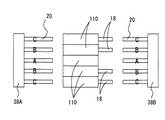
次に芯金ホルダの多段シフト式の装置によって複数の品種の製品を段取り変えなく加工する場合について説明する。まず、芯金ホルダに保持される芯金の数について説明すると、芯金の数は奇数が好ましく図8では3であり、図14のように芯金ホルダ38A, 38Bにそれぞれ5個の芯金を保持するようにしてもよい。異なった品種の同時成形にあたっては各種の形成圧入力が異なる場合であっても芯金圧入シリンダへの偏心荷重が発生しないようにする必要がある。図14ではA, B, Cの三品種の同時加工を行い、その生産量がA<B<Cの場合を想定しており、生産本数の少ないAを中心でその両側でBを最も外側でCを加工するようにするとバランスをとることができる。また、生産量の少ない品種は当然、芯金一本での成形で間に合うものとする。また、5本の芯金A, B, Cを芯金ホルダにフル装備した場合でもA種のみ生産不必要となった場合は図14に示すようにA種用の素材管18を金型110に供給しなければA種用の芯金クランプ型における芯金を脱着せずにそのままで加工を続行することができる。
【0047】
次に、図8及び図9に示す芯金ホルダの多段シフト式の装置によって複数の品種の製品を段取り変えなく加工する場合について説明する。6工程で製造されるA系列の製品と、10工程で製造されるB系列の製品を左右に8段のスタッカを備えた機械により製造する場合を例に挙げると、A系列は左右のスタッカの上側3段、B系列は左右のスタッカの下側5段を使用する。上段から開始しスタッカからの芯金の取出し、芯金の圧入、引き戻しを左右交互に6工程行うことで、A系列の製品の製造を行うことができる。また、下側5段のスタッカについて左右交互に行うことでトータル10工程が実施され、B系列を製品を得ることができる。また、それぞれ8工程にて製造しうる系列C,Dの場合は系列C,Dについて左右の上下4段づつ使用することにより段取り変えなしですませることができる。
【0048】
図15は無段取り変えで多種類の同時加工を行う各種の組み合わせ例a〜rを示している。被加工素材管の形態をシンボリックに○△□にて示している。図15の(イ)は一つの芯金ホルダ38A, 38Bによる同時加工時の組み合わせを示しており、この場合は図14において説明したように奇数の心金が偏心荷重が生じないように対称配置されている。図15の(ロ)は左右のスタッカ36A, 36Bにおけるシフト方向(上下方向)での組み合わせを示しており、生産する品種の組み合わせに応じて適当な組み合わせを採用する。即ち、a,g,mは○、△、□の単品のみの注文しかない場合である。注文数が少なければ素材管をセットする金型を少なくすればよい。○及び△の注文がありうるのであれば例bやhの組み合わせとなり、○及び△の注文数に応じて素材管のセット数を調節する。従って、段取り変えなしに、換言すれば、芯金及び金型の配置をそのままにして必要な品種を必要な数生産することができる。○、△、□の三品種の生産が必要な場合にはその生産数の比率に応じて例c,d、e,f,i,j,k,l,n,о,p,q,rなどのいずれかが選択され、この場合も三品種の同時加工を段取り変えなしに行うことができる。
【図面の簡単な説明】
【図1】図1はこの発明における成形転造の原理を説明する図である。
【図2】図2は金型の断面図であり、(イ)は開放状態(ロ)は閉鎖状態を示す。
【図3】図3は金型の凹部への素材の流れ状態を模式的に示す図であり、(イ)はこの発明、(ロ)は従来技術を示す。
【図4】図4は金型の各種の断面形状を示す図である。
【図5】図5はこの発明により形成しうる凹凸形状の一例を示す図である。
【図6】図6は芯金の側面図である。
【図7】図7は芯金の正面図である。
【図8】図8はこの発明の実施である芯金多段シフト型同時多数加工式の装置の概略的平面図である。
【図9】図9は図8の装置の側面図である。
【図10】図10は割型を分離した状態で示す金型の長手方向断面図である。
【図11】図11は図10の金型の横断面図であり、図10のXI−XI線に沿って表わしたものである。
【図12】図12は芯金加圧のための油圧シリンダの加圧軸心の歪矯正装置を示す側面図である。
【図13】図13は図12のXIII−XIII線に沿って表される矢視断面図である。正き1は図10の金型の横断面図である。
【図14】図14は多種同時加工を行う場合の芯金ホルダにおける芯金配置を示す図である。
【図15】図15はこの発明により多段シフト同時多種加工における無段取り変え加工方式を説明する図である。
【符号の説明】
10…金型
12…上型
14…下型
18…円管
20A, 20B…芯金
20A’, 20B’…芯金
20A”, 20B”…芯金
20−1…芯金の案内部
20−2, 20−4…芯金のテーパ部
20−3, 20−5…芯金の拡径部
32…加圧シリンダ
34…受圧枠
36A, 36B…スタッカ
38A−a, 38A−b, 38A−c…芯金ホルダ
38B−a, 38B−b, 38B−c…芯金ホルダ
40A, 40B…スタッカ枠
42A, 42B…昇降機構
44A, 44B…圧入制御油圧シリンダ
44A−1, 44B−1…圧入制御油圧シリンダのピストン
110…金型
112, 114…割型
120…芯金
120−1…案内部
120−2, 120−4, 120−6…テーパ部
120−3, 120−5, 120−7…拡径部[0001]
BACKGROUND OF THE INVENTION
The present invention is capable of high-precision processing of irregularities in any form deeply engraved on the surface of a part or the entire surface of various cross-sectional mold materials such as triangles, squares, polygons, irregular shapes, and circles having axial cavities. The present invention relates to a linear drive type rolling apparatus that can be efficiently formed. For example, the present invention can be applied to the production of a rack bar that is a steering part of an automobile. However, the present invention is not limited to the production of a rack bar. The present invention can be applied to give a desired surface uneven shape or pattern to the machine functional parts and decorative parts.
[0002]
[Prior art]
A technique for forming a rack bar, which is a steering component of an automobile, from a hollow mold material by rolling is known in principle. That is, in the rolling forming of the rack bar, first, the hollow base material softened by heating is pressed while being held by the mold, whereby the rack forming surface of the hollow bar is flattened. Next, the metal core is press-fitted into the hollow of the hollow bar from the outside while a mold having a linear tooth row on the inner periphery is applied to the flat portion of the hollow bar. The cored bar has a tapered working part, and the meat of the flat part is overhanged by flowing plastically toward the mold by the taper part engaging the flat part on the inner peripheral side. The flat portion is provided with a linear dentition having a shape conforming to the dentition of the mold. Since a product with the expected accuracy cannot be obtained with only one press-in of the mandrel, the mandrel whose working diameter has been changed sequentially is placed in the turret type, and processing is performed while the working diameter of the mandrel is changed in sequence. Has been proposed.
[0003]
[Problems to be solved by the invention]
The turret type requires a turret whose working diameter changes for each split mold, and only one product can be obtained by one press-fitting operation, resulting in extremely deteriorated production efficiency. Since merits of rack bar production can hardly be utilized, the turret type has not been practically used so far.
The present invention has been made in view of this problem, and eliminates the disadvantages of the turret type and enables simultaneous press-fitting of a plurality of mandrel, thereby realizing simultaneous production of a plurality of products and cutting with high accuracy. The purpose is to make it possible to hold the product at a low cost in terms of cost.
[0004]
According to the invention described in claim 1, with respect to the split molds arranged in the horizontal direction, the bed for placing the split mold, and the split mold arranged in the horizontal direction. By pressing so as to be sandwiched from both sides, a pressurizing means for pressurizing and holding a plurality of linear shaped cross-section mold materials in each split mold, and a plurality of core bars are held in parallel in a lateral direction. A metal core holder, and a metal core press-fitting means for simultaneously press-fitting a plurality of metal cores held by the metal core holder toward the axial cavities of the respective mold materials held in each split mold, A linear drive forming and rolling apparatus characterized in that the formation of a shape in accordance with the unevenness of the inner periphery of the die on the outer periphery of the die material by press-fitting the core metal into the die material is performed at once for a plurality of die materials Provided.
[0005]
The operation and effect of the invention of claim 1 will be described. A plurality of laterally divided split molds are arranged in a horizontal stack, and a pressing force is applied to the horizontal stacked split molds from both sides. A plurality of metal cores held by the holder in a state where the mold material is clamped by the respective split molds are simultaneously pressed into the cavities of the respective mold materials, and the respective mold materials are simultaneously rolled. At this time, the overturning moment applied to the bed by the core metal press-fitting is the same as in the case of one split mold. When the split molds are divided vertically and they are lined up side by side and clamped all at once, the clamping force becomes enormous, and if each of the split molds is used separately, the pressure means that matches the number of split mold sets However, according to the present invention, the horizontal split mold is horizontally stacked and clamped from both sides in the horizontal direction, so that one pressurizing means can be completed without increasing the clamping force. A very advantageous effect can be obtained.
[0006]
According to the invention described in claim 2, a plurality of split molds arranged side by side, and a pressurizing means for holding each of the mold materials having a linear irregular cross section by pressurizing each split mold in the mold alignment direction. A stacker for holding a plurality of core metal holders spaced apart in parallel in a stacking manner according to the order of a plurality of steps, and any one of the core metal holders held in a stacking manner on the stacker is taken out from the stacker and used A means for returning the used holder to the core metal holder, and for simultaneously press-fitting and pulling back the core metal held by the one core metal holder toward the axial cavity of the mold material held by the corresponding split mold The cored bar press-in / retracting means is provided, and the cored bar holders are removed from the stacker one by one from a plurality of the cored bar holders stacked on the stacker, and the cored bar is pressed into each mold material differently. It is performed in multiple steps linear drive type molding rolling apparatus according to claim is provided by a metal core.
[0007]
The operation and effect of the invention of claim 2 will be described. The cored bar holder holds a plurality of cored bars at the processing stage as much as possible, and is detachably held with one touch. Set in a stack on the stacker. The metal core holder is taken out from the stacker according to the processing order, and the metal cores held by the metal core holder are pressed together into the corresponding mold materials clamped in the horizontal molds. After being pulled out and repeatedly pressed and pulled back several times, the cored bar is re-stored in the stacker together with the cored bar holder, and the cored bar holder that holds the cored bar in the next processing order is removed from the stacker by operations such as shifting the stacker. In the same manner, the press-fitting of the metal core, the storage in the pullback stacker, and the removal of the metal core holder in the next stage are repeated. With this configuration, there is an effect that a multi-stage rolling operation can be performed very efficiently.
[0008]
According to the invention described in claim 3, in the invention described in claim 1 or 2, a space opened to the outside is formed above the mold, and the material is loaded into the mold and the product is placed in the space. There is provided a linear drive type forming and rolling apparatus characterized in that a loader for carrying out is installed.
[0009]
The operation and effect of the invention of claim 3 will be described. Since the material can be loaded and the product can be carried out from above the mold opened by the loader, the space can be effectively used and the entire apparatus can be made compact.
[0010]
According to the invention described in claim 4, in the invention described in claim 3, the stackers are installed on both sides of the split mold, and the core metal holders are arranged one by one from the plurality of core metal holders stacked on the stacker. Accordingly, a linear drive type forming and rolling apparatus is provided in which the core metal is taken out alternately from the stackers on both sides and the core metal is press-fitted into each mold material in multiple stages using different core metals.
[0011]
The operation and effect of the invention of claim 4 will be described. Since the core bar holders are sequentially taken out from the left and right stackers in the order of the steps, and the core bars of the taken out core bar holders are alternately pressed into the left and right sides, the surface of the thin tube is There is an effect that the rolling of the deep uneven pattern can be carried out with high accuracy.
[0012]
According to the invention of claim 5, in the invention of claim 4, the metal core in the metal core holder from the stacker on the opposite side to the reciprocating drive mechanism for the metal core in the metal core holder from the stacker on one side A linear drive type forming and rolling apparatus is provided, which is driven at a timing independent of the reciprocating drive mechanism.
[0013]
The operation and effect of the invention of claim 5 will be explained. The selection of the left and right independent drive timings enhances the compatibility with the high-mix low-volume production system, so that different products can be changed by one machine without changing the setup or with the minimum number of paragraphs. Can be produced in
[0014]
According to the invention described in claim 6, the split mold, the pressurizing means for pressing the split mold in the mold aligning direction to hold the template material having a linear irregular cross section, and the core bar are held by the split mold. And a hydraulic cylinder means for press-fitting and pulling back toward the axial cavity of the mold material, the hydraulic cylinder means being attached to a reverse deflection rib for offsetting the deflection angle. Manufacturing equipment is provided.
[0015]
The operation and effect of the invention of claim 6 will be described. In the implementation of the present invention, the split mold clamping direction and the core metal press-fitting direction are likely to be arranged in an X and Y cross shape. In the case of this cross arrangement, it is difficult to maintain a work post in the middle of both the X-axis pressurizing means and the Y-axis pressurizing means in order to maintain workability, and it becomes cantilever support. In this case, structurally, the opening of the protruding jaw due to stress strain occurs, and the pressurization axis tends to shift. This deviation may shorten the life of the cored bar. On the other hand, in the seventh invention, a cylinder is not provided directly on the jaw part of the pressurizing device, but a reverse bending rib for offsetting the bending angle is added, and a cylinder is provided on this, so that the gap between the jaw part and the rib is reduced. Distortions in directions opposite to each other are generated, and the distortions can be canceled or reduced, and misalignment of the axis can be prevented or minimized.
[0016]
DETAILED DESCRIPTION OF THE INVENTION
1 and 2 schematically show the rolling formation of a hollow rack, which is a steering component of a vehicle, from a metal circular tube as one embodiment of the present invention. A mold 10 as a split mold includes an upper mold 12 and a lower mold 14, and FIG. 2 and a cross section of the mold 10 are shown in an open state in (A) and in a closed state in (B). The upper die 12 has a rack tooth 12-1 in a concave portion in the longitudinal direction on the inner peripheral surface thereof facing the lower die 14, while the lower die 14 has a cross section on the upper surface facing the upper die 12. A semicircular arc-shaped longitudinal groove 14-1 is formed. 2A shows a state in which the circular pipe 18 has already been placed in the longitudinal groove 14-1 in the semicircular arc cross section of the lower mold 14. FIG.
[0017]
When the mold 10 is closed as shown in (b) of FIG. 2 by moving the upper mold 12 and the lower mold 14 from the state shown in FIG. The upper half 18-1 facing the surface is flattened to be a deformed base material to be subjected to rack-tooth molding and rolling. FIG. 1 is a longitudinal sectional view of the mold 10 in the closed state shown in FIG. The mold 10 is only about 1/2 or less in length of the material tube 18 having a circular cross section. And one end of the circular tube 18 is the mold 10 and a hook, but the opposite end protrudes more than 1/2 length. However, the tooth portion 12-1 formed on the lower surface of the upper mold 12 facing the lower mold 14 stays somewhat in front of the end surface of the mold 10, and therefore the material tube 18 is closed when the mold 10 is closed. The left end 18A and the right end 18B are not flatly crushed, in other words, both ends 18A and 18B of the material pipe 18 remain in a circular cross section.
[0018]
In the embodiment of the present invention described with reference to FIGS. 1 and 2, the upper surface, which is the rack forming surface of the material pipe 18, is flattened = the formation of the profile material is closed by the rack rolling forming mold 10, that is, the upper die 12 and the lower die 12. This is done by combining with the mold 14. That is, the rack-like tooth portion 12-1 of the upper die 12 is located at a position where the distance from the bottom surface of the lower die 14 is a little more than half of the outer diameter of the material tube 18 when the die is closed. The rack-like teeth 12-1 are flattened as shown in FIG. Therefore, the mold 10 can be successively transferred to the next step without being opened. Accordingly, the process can be wrapped, and the clamping operation can be performed only once, so that there is an advantage that the chance of occurrence of scratches due to clamping can be eliminated. Also, since the rolling mold is used for deforming, the accuracy of deforming is lower than when using the original mold dedicated to deforming, but the required accuracy is not so high. As far as it turns out there is no practical problem. For flattening, it is possible to take a normal process such as crushing the upper surface of the circular tube with a dedicated die, then opening the die, and clamping to a rolling die.
[0019]
In FIG. 1, the material pipe 18 after the flattening of the cross section held between the split dies 12 and 14 is subjected to the rolling process of the present invention by press-fitting and pulling back the core metal. Hereinafter, this will be described. The core bars 20A and 20B are disposed opposite to each other in the axial direction on both sides of the material pipe 18 whose upper surface is flattened by being clamped by the mold 10. The metal cores 20A and 20B have a cross-sectional shape that conforms to the cross-sectional shape of the portion of the material pipe 18 that has been flattened as shown in FIG. As shown in FIG. 1, the tips of the core bars 20A and 20B form a guide portion 20-1, which serves as a guide for introduction into the portion of the material pipe 18 having a flattened cross section. A diameter-enlarged portion 20-3 continues behind the guide portion 20-1 via a tapered portion 20-2, and the tapered portion 20-2 is a flat portion 18- of the material pipe 18 when the core bars 20A and 20B are press-fitted. By engaging 1, the metal pipe is made to flow metal from the inside to the outside toward the unevenness of the rack tooth-like part 12-1 of the mold, and the flat part 18-1 of the material pipe is complementary to the uneven shape. A rack-like tooth portion is formed. In FIG. 1, the core bars 20A and 20B have a first diameter-expanded part 20-3 followed by a second diameter-expanded part 20-5 via a taper part 20-4. Sequential multi-stage metal flow is obtained.
[0020]
FIG. 1 shows an initial state in which the left core 20A is press-fitted into the material pipe 18 just flattened as a first step. The left metal core 20A is press-fitted until the last diameter-expanded portion 20-5 reaches the right end of the flat portion 18-1 of the material tube, and then the metal core 20A is completely removed from the material tube 18. Move to the left.
[0021]
The right core 20B starts to move to the left in FIG. 1 with the timing difference between the removal of the left core 20A and the appropriate lapping, and the right core 20B is introduced into the internal cavity of the material tube 18. The diameter-enlarged portion induces a metal flow process similar to that described for the left core 20A.
[0022]
The press-fitting / removal of the right core metal 20A and the press-fitting / removal of the left core metal 20B continued thereto are repeated several times. That is, the press-fitting of the left and right core bars 20A and 20B into the material pipe 18 is repeated a plurality of times alternately. Repetitive press-fitting of the metal cores 20A and 20B into the internal cavity of the material pipe 18 can promote a reliable flow of meat into the concave portion of the mold. That is, only one press-fitting of the mandrel is insufficient in the flow of meat, and there is a possibility that high-precision rolling cannot be performed, but such a fear can be avoided by repeated press-fitting. In addition, by alternately press-fitting the left and right cored bars 20A and 20B, an even metal flow can be obtained with respect to the concave portion of the mold, and there is an effect that highly accurate rolling can be realized. That is, FIG. 3 schematically shows the flow state of the meat ascertained from the layer formation state of the tooth portion in the cross-sectional micrograph of the actual tooth portion of the rack obtained by rolling. Arrow f 1 It can be seen that the flow state of the meat of the present invention in which alternating press-fitting as shown in FIG. On the other hand, (b) indicates that the press-fitting direction of the core bar is indicated by an arrow f. 2 In this case, it can be seen that there is a deviation in the flow of the meat and entrainment has occurred. Such a non-uniform flow state of the meat causes non-uniform stress remaining after the completion of the rack tooth molding and the accompanying return of elastic strain, that is, non-uniformity of the springback amount, which causes a decrease in accuracy of the product. However, in the present invention, such a problem is solved because an even flow of meat is ensured.
[0023]
Referring again to FIG. 1, the vertical shift of the cored bar will be described. A plurality of pairs of left and right cored bars 20A, 20B are provided in the vertical direction. In FIG. 1, another pair of core bars 20A ′ and 20B ′ is shown below the pair of core bars 20A and 20B, but the required number of core pairs is arranged in the vertical direction. The shape of the core bar such as the working diameter is gradually changed in the shift direction so that the processing proceeds step by step at every shift. The multi-stage cored bar pairs are stacked on left and right stackers not shown in FIG. 1, and processing is performed while shifting the stackers. That is, after the first stage processing is performed by alternately press-fitting the core bars 20A and 20B of the first processing stage, the core bar holders in the left and right stackers are shifted upward as indicated by the arrow a during standby, The second-stage metal cores 20A ′ and 20B ′ are aligned with the material pipe 18, and the metal cores 20A ′ and 20B ′ are alternately press-fitted into the internal cavity of the material pipe 18 to perform the second stage processing. Thereafter, the necessary number of steps are similarly processed. In this way, by changing the core metal little by little and performing the processing over a number of stages, there is an effect that it is possible to accurately form a deep uneven shape even for a thin material pipe.
[0024]
4 (a) to 4 (d) illustrate various deformed mold materials that can carry out the present invention and a split structure of a mold for imparting an uneven shape thereto. FIG. 4A shows a material 18A obtained by flattening the upper half of the circular pipe described in relation to FIGS. The mold is composed of an upper mold 12A and a lower mold 14A, and the upper mold 12A has a concavo-convex part 12A-1 facing the flat part of the material 18A. An uneven shape complementary to the unevenness is formed.
[0025]
4B shows a material 18B having a rectangular cross section, and the material 18B is clamped between the upper die 12B and the lower die 14B. The upper mold 12B has a concavo-convex portion 12B-1 facing one side surface of the material 18B, and a concavo-convex complementary to the concavo-convex shape is formed on one side surface of the material 18B by press-fitting a cored bar.
[0026]
FIG. 4 (c) shows a material pipe 18C having a hexagonal cross section. The mold is divided into three parts consisting of 12C, 12C ′ and 14C, and irregularities 12C are formed on the inner surfaces of the respective split molds 12C, 12C ′ and 14C. -1, 12C'-1, and 14C-1 are formed, and by pressing the core metal, irregularities complementary to the irregularities can be formed on every other side surface of the hexagonal cross-section material tube 18B.
[0027]
FIG. 4D shows a material tube 18D having a triangular cross section, and the mold is composed of an upper mold 12D and a lower mold 14D, and an uneven surface 12D-1 is formed on the inner surface of the upper mold 12D. As a result of the press-fitting, an irregularity complementary to this irregularity can be formed on the upper surface of the triangular cross-section material tube 18D.
[0028]
FIG. 5 exemplifies various variations of the concavo-convex shape applied to the flat surfaces 12A-1, 12B-1, 12C-1, and 12D-1 of the material tube, where I is a chevron row, II is a concavo-convex key, III indicates an uneven ridge pattern, and various other uneven shapes or patterns can be applied to the surface of the material tube by implementing the present invention.
[0029]
6 and 7 show a more specific structure of a cored bar having a rectangular cross section that can be used in the embodiment of FIG. The cored bar 120 includes a guide part 120-1 at the tip, a first taper part 120-2 following the guide part 120-1, and a first diameter-expanding part 120- following the first taper part 120-2. 3, a tapered portion 120-4 following the first expanded diameter portion 120-3, a second expanded diameter portion 120-5 following the second tapered portion 120-4, and a second expanded diameter portion The third taper part 120-6 following 120-5, the third diameter enlarged part 120-7 following the third taper part 120-6, and the third diameter enlarged part 120-7 follow. It consists of a reduced diameter portion 120-8 and a buckling prevention contact portion 120-9 that follows the reduced diameter portion 120-8 and extends near the base of the holder.
[0030]
The cored bar is introduced into the material pipe from the guide part 120-2 when the cored bar 120 is press-fitted into the material pipe, and the first enlarged diameter part 120-3 is inside the material pipe via the first taper part 120-2. Engagement with the circumference induces the flow of the material meat to the concave and convex portions on the inner circumference of the mold. When the press-fitting further proceeds, the metal flow of the same material is caused by the taper portions 120-4 and 120-6 and the enlarged diameter portions 120-5 and 120-7. Since the expanded diameter portions 120-3, 120-5, and 120-7 are subjected to unit surface pressure several times the compressive strength of the material during the expansion operation, the material of the core metal is subjected to phosphate treatment. Is preferred. Moreover, in order to cope with the oil film breakage during operation, the enlarged diameter portions 120-3, 120-5, and 120-7 are subjected to a forming process such as an extremely small labyrinth groove or a fine textured pattern that can be an oil pot on the surface. Is preferred. Such an oil pot is preferably provided not only on the molding part but also on the opposing surface that receives a reaction force during molding. Or you may provide an oil pot in the perimeter of a shaping | molding part.
[0031]
In FIG. 6, the flow of meat in one press-fitting is provided by providing tapered portions 120-2, 120-4, 120-6 whose diameters increase stepwise and enlarged diameter portions 120-3, 120-5, 120-7. Are sequentially performed, and the total amount of meat flow can be increased, and productivity can be increased. In this case, the containment of the lubricating oil becomes strong, and there is a possibility that the modeling shape by rolling is distorted. The reduced diameter portion 120-8 provided behind the enlarged diameter portion 120-7 achieves a function of preventing this by escaping the contained lubricating oil.
[0032]
As the core metal continues to be press-fitted, the contact portion 120-9 is closely fitted into the inner periphery of the material pipe, and achieves the function of receiving a load in the buckling direction applied to the core metal. That is, the contact portion 120-9 is slightly in the material pipe on the base side of the core metal after the diameter-enlarged portions 120-3, 120-5, and 120-7 are exceeded when the core metal is pressed into the material pipe more than a certain depth. Rolling on the tip side is advanced in a state of being fitted in the gap. Therefore, even in the case of rolling a long rack bar, the material is stably supported by the contact portion 120-9, allowing a margin for the buckling limit and increasing the amount of metal flow during one press-fitting. In this case, the required durability of the cored bar can be ensured.
[0033]
Next, a multiple bar metal simultaneous press-fitting and multistage shift type rack bar rolling apparatus will be described with reference to FIGS. 8 and 9, reference numeral 30 denotes a bed on which a mold is placed, and a plurality of (three in the figure) molds 110 as laterally split molds are arranged in a horizontal direction. The Each mold 110 is composed of two split molds 112, 114. One split mold 112 has rack-like irregularities as in FIG. 2, and the other split mold 114 accommodates a tubular material. A semicircular groove is formed.
[0034]
A pressure cylinder 32 is provided on one side in the arrangement direction of the molds 110 on the bed 30, and a pressure receiving frame 34 is disposed on the other side. The pressurizing cylinder 32 includes a piston 32-1, and in a state where the piston 32-1 is pulled back, each mold 110 is divided into the horizontal divisions constituting the die 110 as shown in the upper half of FIG. The molds 112 and 114 are separated (see also (A) in FIG. 2), and a space S for inserting the material pipe can be formed therebetween. When the piston 32-1 of the pressurizing cylinder 32 is advanced for pressurization as shown in the lower half of FIG. 8 by the supply of hydraulic pressure, the split molds 112 and 114 are moved laterally on the bed 30 and are The stacked molds 110 are sandwiched and held between the piston 32-1 and the pressure receiving frame 34, and the split molds 112 and 114 constituting each mold 110 are combined in the same manner as shown in FIG. As shown in the lower half of FIG. 8, the material pipe 18 (shown by a broken line) is clamped between the split dies 112 and 114.
[0035]
Stackers 36A and 36B are arranged on both sides of the mold 110 in the direction orthogonal to the horizontal stacking direction, that is, on both ends in the axial direction of the material pipe 18 clamped by the split molds 112 and 114. As shown in FIG. 9, the left stacker 36A has core metal holders 38A-a, 38A-b, 38A-c arranged in multiple stages in the vertical direction (the number of core metal holders is three in the figure, but other than that And a stacker frame 40A for holding these core metal holders 38A-a, 38A-b, 38A-c in a vertically slidable state, and a stacker frame 40A And an elevating mechanism 42A for vertically moving the metal core holders 38A-a, 38A-b, 38A-c. Each of the core bar holders 38A-a, 38A-b, and 38A-c has a structure in which a predetermined number of core bars 20A can be attached and detached in a one-touch manner. Further, a press-fit control hydraulic cylinder 44A is provided outside the left core bar holder stacker 36A, and the piston 44A-1 of the press-fit control hydraulic cylinder 44A is a core metal holder 38A-a, 38A-b, which is held by the stacker 36A. 38A-c is sequentially engaged, and the selected metal core holder is moved from the right to the left in the figure, and the metal core held by the metal core holder is directed to the internal cavity of the material tube 18 clamped in the metal mold. As described with reference to FIG. 1, unevenness having a shape conforming to the unevenness formed on the inner periphery of the mold is provided on the outer surface of the material tube.
[0036]
When the press-fitting with the plurality of cores 20A held by one cored bar holder 38A-a is finished, the cored bar holder 38A-a is retracted leftward to the part of the stacker frame 40A, and the stacker frame 40A is moved by the lifting mechanism 42A. The core metal holder inside is shifted one step in the vertical direction (for example, upward), and the core metal holder 38A-c in the next processing order is pushed rightward in FIG. 9 by the piston 44A-1, and the metal core holder 38A-c. The cored bar 20A ′ held in is pressed into the axial internal cavity of the material pipe 18, and the rolling operation of the next stage is performed.
[0037]
In FIG. 9, the structure of the stacker 36B arranged on the right side of the mold bed 30 is the same as that on the left side, and the core holders 38B-a, 38B-b, 38B-c arranged in multiple stages in the vertical direction, and the core Stacker frame 40B that holds the metal holders 38B-a, 38B-b, 38B-c slidably up and down, and the core metal holders 38B-a, 38B-b, 38B-c are moved up and down in the stacker frame 40B. And an elevating mechanism 42B. Further, a press-fit control hydraulic cylinder 44B is provided outside the right-hand core holder stacker 36B, and the piston 44B-1 of the press-fit control hydraulic cylinder 44B is a core metal holder 38B-a, 38B-b, which is held by the stacker 36B. 38B-c is sequentially engaged, and the selected metal core holder is moved from the right to the left in the figure, and the metal core held by the metal core holder is directed to the internal cavity of the material tube 18 clamped to the metal mold 110. As described with reference to FIG. 1, unevenness having a shape conforming to the unevenness formed on the inner periphery of the mold is provided on the outer surface of the material tube. Further, the core bar holder in the stacker frame 40B is shifted by one step in the vertical direction by the lifting mechanism 42B.
[0038]
The left and right core metal holders are shifted in accordance with the progress of the press-fitting stage, and the left and right core bars are alternately press-fitted into the material pipe 18 as described with reference to FIG. . That is, in FIG. 9, the second stage rolling operation is performed, and the core 20A held by the left core holder 38A-b is moved rightward by the piston 44A-1 of the press-fit cylinder. The metal 20A is press-fitted all at once into the respective material pipes 18 clamped to the horizontally stacked dies 110. When the press-fitting is finished, the metal core 20A held by the metal core holder 38A-b is pulled back to the left side, The cored bar 20B held in the second-stage cored bar holder 38B-b on the right side after being pulled back is moved to the left in FIG. 9 by the piston 44B-1 of the press-fit cylinder 44B, and the cored bar 20B is horizontally stacked. Are simultaneously press-fitted into the respective material tubes 18 clamped in the mold 110. Then, the left and right press-fitting of the core metal holders 38A-b and 38B-b are repeatedly performed a plurality of times as described with reference to FIG. When the rolling operation at this stage is completed, the left stacker and the right stacker are shifted in a predetermined direction, for example, upward, and held in the core metal holders 38A-c and 38B-c for the next stage. A plurality of cored bars 20A ′ and 20B ′ are simultaneously press-fitted into the material pipe alternately left and right, and the rolling operation at this stage is performed.
[0039]
In the rolling method of FIGS. 8 and 10, a plurality of horizontally divided dies 110 are horizontally stacked and pressed from both sides so that the split dies 112 and 114 constituting each die are held together. When the core metal is press-fitted into the material tube held by the mold, the overturning moment M that the mold receives on the bed 30 by the core metal pressure input applies a pressure P to the distance L from the bed to the center of the mold. However, since M = L × P, since a plurality of molds are horizontally stacked, there is an advantage that the value of the overturning moment is exactly the same as in the case of one mold.
[0040]
Further, regarding the pressure applied by the hydraulic cylinder 32 that holds the mold 110 closed when the core metal is press-fitted, the holding force when a plurality of molds are stacked in the pressurizing direction (lateral direction) is the reaction force between adjacent molds. By canceling out the force, the applied pressure is the same as that for holding one mold, and it is not necessary to use a large hydraulic cylinder 32 because of the multiple molds.
[0041]
In the embodiment of the present invention, the moving direction of the cores 20A and 20B and the moving direction of the mold 110 are in a horizontal plane, but are mutually projected in a cross shape as shown in FIG. Therefore, as shown in FIG. 9, a substantially open space is formed above the mold 110. Therefore, the loading of the new material pipe 18 ′, which is a workpiece, into the mold 110 and the removal of the product can be performed vertically by the loader 111 as indicated by arrows b 1 and b 2. Further, since the space above the mold is completely open, there is an effect that the maintenance becomes easy. Also, since the stacker frames 40A and 40B for the mandrel holders 38A-a, 38A-b, 38A-c, 38B-a, 38B-b, and 38B-c can be opened upward, the maintenance is performed. Can also be facilitated.
[0042]
10 and 11 show the cleaning liquid injection nozzle and the biting work protruding device in the split molds 112 and 114 constituting each mold 110. FIG. That is, excessive accumulation of heat generated by plastic forming by continuous molding requires a large amount of coolant showering. In addition, when opening the mold for workpiece removal at the end of continuous molding after one-time clamping, the cleaning liquid is strongly sprayed simultaneously onto the concave-convex rolled mold surface and the opposite clamp surface to treat the phosphate film. It is necessary to remove the waste and other garbage every time to keep the mold clean and prevent scratches. For this purpose, it is desirable to shorten the head-to-head distance between the cleaning liquid and the bed surface so that quick washing is performed. That is, the injection nozzles 112-1 and 114-1 are opened on the molding surfaces of the split dies 112 and 114, and when the split dies are opened after rolling, the cleaning liquid is transferred from the injection nozzles 112-1 and 114-1 to the other party. It is sprayed toward the split mold and can be cleaned and cooled. Further, the biting work projecting device is constituted by pins 112-2 and 114-2 so that the work bitten into the inner surface of the mold can be ejected by the projecting operation of the pins 112-2 and 114-2. By adopting this structure, it is possible to prevent damage to the clamp once.
[0043]
12 and 13 show an example of a specific support structure of a cylinder for core metal press-fitting. 12 and 13 only show the hydraulic cylinder 44 for press-fitting the core metal on the right side of the mold 110 for the sake of simplicity, a similar hydraulic cylinder is also provided on the left side of the mold 11 in accordance with FIG. Reference numeral 130 denotes a hydraulic cylinder support, and a support frame 132 having a U-shaped cross section is attached on the hydraulic cylinder support 130. From the inner surface of the upper side of the support frame 132, a pair of reversely bent ribs 134 are formed in a cantilever manner. The main body of the hydraulic cylinder 44 is fixed to the reverse bending rib 134. A piston rod 44-1 extends from the hydraulic cylinder 44, a core metal holder 38 is attached to the tip of the piston rod 44-1, and the core metal 20 is held by the core metal holder 38. When the piston rod 44-1 extends, the core metal holder 38 at the tip of the piston rod 44-1 and the core metal 20 held by the core metal holder 38 expand, and the material tube held by the metal mold 110 on the mold 110 is expanded. 18 is press-fitted and patterning is performed on the flattened surface of the material tube 18.
[0044]
The action of the reverse bending rib 134 of FIGS. 12 and 13 will be described. The hydraulic cylinder 44 is cantilevered, and the support frame 132 is bent upward by the stress when the cored bar 20 is pressed into the material pipe 18. If this bending of the support frame 132 is left as it is, that is, if the hydraulic cylinder 44 is provided directly on the support frame 132, the pressing shaft center of the cored bar 20 is shifted upward, causing a reduction in the life of the cored bar 20. On the other hand, in the embodiment of FIGS. 12 and 13, the hydraulic cylinder 44 is installed on the reverse bending rib 134 that is cantilevered from the upper plate of the support frame 132. The bending direction of the reverse bending rib due to the stress at the time of press-fitting the metal core 20 with respect to the material pipe 18 is downward opposite to the bending direction of the support frame 132. Therefore, by appropriately designing the reverse deflection rib 134, the upward deflection of the support frame 132 can be offset by the downward deflection of the reverse deflection rib 134, so that the pressing shaft center of the core metal 20 does not shift or Since it becomes small, there exists an effect which can extend the lifetime of the metal core 20. FIG.
[0045]
The structure of the split molds 112 and 114 constituting the mold 110 used in the apparatus shown in FIGS. 8 and 9 will be described. In the case where a high processing accuracy is not required or the shape is easily processed, FIG. As described in relation to the above, the concave-convex mold itself can be configured as a clamp mold. However, for those that require accuracy and have a high degree of difficulty in shape processing, it is necessary to have a configuration in which the concavo-convex molded portion itself is processed independently and the die is embedded in the clamp split mold. In this case, the clamp split mold is a split holder. In this case, a strong spray nozzle for cleaning liquid for preventing scratches is embedded in this split clamp from the viewpoint of installation at the shortest distance. In addition, if the work is bitten, the work picking device may be damaged. Therefore, it is preferable to incorporate a forced removal device for the workpiece into the clamp mold. In addition, if there is variation in the opening of the work, it causes a supply failure of the work and becomes a factor of productivity inhibition. Therefore, it is preferable to incorporate a device such as an injection nozzle work knockout type opening size regulation for eliminating this. .
[0046]
Next, a case where a plurality of types of products are processed without changing the setup by a multistage shift type apparatus of the core metal holder will be described. First, the number of cores held by the cored bar holder will be described. The number of cored bars is preferably an odd number, and is 3 in FIG. 8. As shown in FIG. 14, the cored bar holders 38A and 38B each have 5 cored bars. May be held. In simultaneous molding of different varieties, it is necessary to prevent an eccentric load from being applied to the core metal press-fitting cylinder even when various forming pressure inputs are different. In FIG. 14, three types of A, B, and C are simultaneously processed, and it is assumed that the production amount is A <B <C, with B being the outermost on both sides centering on A with a small number of production. If C is processed, a balance can be obtained. Naturally, varieties with a small production volume will be in time for molding with a single cored bar. In addition, even when five cores A, B, and C are fully equipped in the core holder, if only type A is not required to be produced, as shown in FIG. If it is not supplied, the processing can be continued as it is without attaching and detaching the core metal in the type A core metal clamp die.
[0047]
Next, a case where a plurality of types of products are processed without changing the setup using the multistage shift type apparatus of the core metal holder shown in FIGS. 8 and 9 will be described. As an example, A-series products manufactured in 6 steps and B-series products manufactured in 10 steps are manufactured on a machine equipped with 8 stackers on the left and right. The upper three stages and the B series use the lower five stages of the left and right stackers. Starting from the upper stage, taking out the metal core from the stacker, press-fitting the metal core, and pulling it back alternately on the left and right, the A series product can be manufactured. In addition, a total of 10 steps are performed by alternately performing the left and right stackers on the lower five stages, and products can be obtained from the B series. Further, in the case of series C and D that can be manufactured in 8 steps, it is possible to eliminate the setup change by using 4 stages on the left and right sides for series C and D.
[0048]
FIG. 15 shows various combinations a to r in which many types of simultaneous machining are performed without step change. The form of the material tube to be processed is symbolically indicated by ○ △ □. FIG. 15 (a) shows a combination at the time of simultaneous machining by one core bar holder 38A, 38B. In this case, as described in FIG. 14, an odd number of core bars are symmetrically arranged so that no eccentric load is generated. Has been. FIG. 15B shows combinations in the shift direction (vertical direction) in the left and right stackers 36A and 36B, and an appropriate combination is adopted according to the combination of the types to be produced. That is, a, g, and m are orders where only single items of ◯, Δ, and □ are ordered. If the number of orders is small, the number of molds for setting the material pipes may be reduced. If orders of ○ and △ are possible, the example b and h are combined, and the number of sets of material tubes is adjusted according to the number of orders of ○ and △. Therefore, in other words, the necessary number of necessary varieties can be produced without changing the setup, in other words, with the arrangement of the core metal and the metal mold as they are. When production of three varieties of ○, △, and □ is required, examples c, d, e, f, i, j, k, l, n, о, p, q, r according to the ratio of the production numbers In this case, the simultaneous processing of the three types can be performed without changing the setup.
[Brief description of the drawings]
FIG. 1 is a diagram for explaining the principle of forming and rolling in the present invention.
FIG. 2 is a cross-sectional view of a mold, wherein (a) shows an open state (b) and shows a closed state.
FIGS. 3A and 3B are diagrams schematically showing a flow state of a material into a concave portion of a mold. FIG. 3A shows the present invention, and FIG. 3B shows a prior art.
FIG. 4 is a diagram showing various cross-sectional shapes of a mold.
FIG. 5 is a diagram showing an example of a concavo-convex shape that can be formed according to the present invention.
FIG. 6 is a side view of the cored bar.
FIG. 7 is a front view of a cored bar.
FIG. 8 is a schematic plan view of a cored bar multistage shift type simultaneous multiple machining type apparatus which is an embodiment of the present invention.
FIG. 9 is a side view of the apparatus of FIG.
FIG. 10 is a longitudinal sectional view of the mold showing the split mold in a separated state.
11 is a cross-sectional view of the mold shown in FIG. 10 and is represented along the line XI-XI in FIG.
FIG. 12 is a side view showing a distortion correcting device for a pressurizing axis of a hydraulic cylinder for pressurizing a mandrel.
13 is a cross-sectional view taken along the line XIII-XIII of FIG. Correct 1 is a cross-sectional view of the mold of FIG.
FIG. 14 is a diagram showing a cored bar arrangement in a cored bar holder when performing multi-type simultaneous machining.
FIG. 15 is a diagram for explaining a non-step change machining method in multi-shift simultaneous multi-machining according to the present invention.
[Explanation of symbols]
10 ... Mold
12 ... Upper mold
14 ... Lower mold
18 ... Pipe
20A, 20B ... Core
20A ', 20B' ... Core
20A ", 20B" ... Core
20-1 ... Core guide part
20-2, 20-4 ... Tapered portion of cored bar
20-3, 20-5 ... diameter-expanded part of the core
32 ... Pressure cylinder
34 ... Pressure receiving frame
36A, 36B ... Stacker
38A-a, 38A-b, 38A-c ... Core bar holder
38B-a, 38B-b, 38B-c ... Metal core holder
40A, 40B ... Stacker frame
42A, 42B ... Elevating mechanism
44A, 44B ... Press-fit control hydraulic cylinder
44A-1, 44B-1 ... Piston of press-fitting control hydraulic cylinder
110 ... Mold
112, 114 ... split mold
120 ... Core
120-1 ... Guide
120-2, 120-4, 120-6 ... Tapered portion
120-3, 120-5, 120-7 ... Expanded portion