JP3607088B2 - Method and system for continuous simultaneous removal of nitrogen and suspended solids from wastewater - Google Patents
Method and system for continuous simultaneous removal of nitrogen and suspended solids from wastewater Download PDFInfo
- Publication number
- JP3607088B2 JP3607088B2 JP24933598A JP24933598A JP3607088B2 JP 3607088 B2 JP3607088 B2 JP 3607088B2 JP 24933598 A JP24933598 A JP 24933598A JP 24933598 A JP24933598 A JP 24933598A JP 3607088 B2 JP3607088 B2 JP 3607088B2
- Authority
- JP
- Japan
- Prior art keywords
- water
- nitrogen
- sewage secondary
- suspended solids
- treated water
- Prior art date
- Legal status (The legal status is an assumption and is not a legal conclusion. Google has not performed a legal analysis and makes no representation as to the accuracy of the status listed.)
- Expired - Lifetime
Links
Images
Classifications
-
- C—CHEMISTRY; METALLURGY
- C02—TREATMENT OF WATER, WASTE WATER, SEWAGE, OR SLUDGE
- C02F—TREATMENT OF WATER, WASTE WATER, SEWAGE, OR SLUDGE
- C02F3/00—Biological treatment of water, waste water, or sewage
- C02F3/02—Aerobic processes
- C02F3/12—Activated sludge processes
- C02F3/22—Activated sludge processes using circulation pipes
- C02F3/226—"Deep shaft" processes
-
- C—CHEMISTRY; METALLURGY
- C02—TREATMENT OF WATER, WASTE WATER, SEWAGE, OR SLUDGE
- C02F—TREATMENT OF WATER, WASTE WATER, SEWAGE, OR SLUDGE
- C02F3/00—Biological treatment of water, waste water, or sewage
- C02F3/02—Aerobic processes
- C02F3/10—Packings; Fillings; Grids
- C02F3/105—Characterized by the chemical composition
- C02F3/107—Inorganic materials, e.g. sand, silicates
-
- C—CHEMISTRY; METALLURGY
- C02—TREATMENT OF WATER, WASTE WATER, SEWAGE, OR SLUDGE
- C02F—TREATMENT OF WATER, WASTE WATER, SEWAGE, OR SLUDGE
- C02F2303/00—Specific treatment goals
- C02F2303/16—Regeneration of sorbents, filters
-
- C—CHEMISTRY; METALLURGY
- C02—TREATMENT OF WATER, WASTE WATER, SEWAGE, OR SLUDGE
- C02F—TREATMENT OF WATER, WASTE WATER, SEWAGE, OR SLUDGE
- C02F2305/00—Use of specific compounds during water treatment
- C02F2305/06—Nutrients for stimulating the growth of microorganisms
-
- Y—GENERAL TAGGING OF NEW TECHNOLOGICAL DEVELOPMENTS; GENERAL TAGGING OF CROSS-SECTIONAL TECHNOLOGIES SPANNING OVER SEVERAL SECTIONS OF THE IPC; TECHNICAL SUBJECTS COVERED BY FORMER USPC CROSS-REFERENCE ART COLLECTIONS [XRACs] AND DIGESTS
- Y02—TECHNOLOGIES OR APPLICATIONS FOR MITIGATION OR ADAPTATION AGAINST CLIMATE CHANGE
- Y02W—CLIMATE CHANGE MITIGATION TECHNOLOGIES RELATED TO WASTEWATER TREATMENT OR WASTE MANAGEMENT
- Y02W10/00—Technologies for wastewater treatment
- Y02W10/10—Biological treatment of water, waste water, or sewage
Landscapes
- Life Sciences & Earth Sciences (AREA)
- Chemical & Material Sciences (AREA)
- Engineering & Computer Science (AREA)
- Hydrology & Water Resources (AREA)
- Biodiversity & Conservation Biology (AREA)
- Microbiology (AREA)
- Environmental & Geological Engineering (AREA)
- Water Supply & Treatment (AREA)
- Organic Chemistry (AREA)
- Chemical Kinetics & Catalysis (AREA)
- General Chemical & Material Sciences (AREA)
- Materials Engineering (AREA)
- Inorganic Chemistry (AREA)
- Purification Treatments By Anaerobic Or Anaerobic And Aerobic Bacteria Or Animals (AREA)
- Filtration Of Liquid (AREA)
Description
【0001】
【発明の属する技術分野】
本発明は、下水、し尿などの生活廃水、産業廃水、埋立地浸出水等の二次処理水 、とくに下水の二次処理水を移床式上向流ろ過装置に供給して、混入する窒素成分 を生物的に分解し懸濁物質をろ過する、下水二次処理水中の窒素窒素成分及び懸濁 物質の連続同時除去方法及び除去システムに関する。
【0002】
【従来の技術】
下水などの廃水中に含まれる窒素成分の除去には、主に廃水を硝化菌と脱窒菌とに順次作用させて生物的に分解、除去する方法が用いられている。このうち代表的な窒素除去プロセスとして、廃水の二次処理を含め硝化、脱窒の機能を分離して処理する硝化・脱窒システム、硝化液を脱窒工程に循環する脱窒・硝化システムなどのプロセスがあげられる。また、下水の二次処理水などを処理するために、既設の処理装置の後段に新しく固定床生物膜ろ過装置を設け、二次処理水に水素供与体としてメタノールを添加し脱窒処理を行う方法も広く実施されている。
【0003】
【発明が解決しようとする課題】
ところで、前記の窒素成分除去プロセスは、運転コストは低く押さえられるが長い処理滞留時間を要する割に窒素除去率がそれ程高くないとか、窒素除去率は高いが過剰な生物膜が形成されて閉塞しやすく、剥離した生物膜が処理水中に混入するとか、ろ床の閉塞はないが逆に生物保持量が小さいなど、いずれも一長一短である。一方、移床式上向流砂ろ過器は、ろ床での生物保持が困難であり、通常のろ過速度では十分な窒素除去が行えない。本発明者は、主に下水の二次処理水などを対象に効率のよい脱窒及び同時に懸濁物質を除去する方法とそのシステムを研究した結果、本発明を完成することができた。
【0004】
【課題を解決するための手段】
本発明の要点を図面を参照して説明する。本発明は、窒素化合物や懸濁物質(S S)を含む下水二次処理水を供給被処理水として、水素供与体を添加し、ろ材連続 逆洗機能を有する移床式上向流ろ過装置1に送入し、さらにろ過装置1から排出さ れる逆洗排水の一部を供給下水二次処理水中に返送して添加することにより、下水 二次処理水の窒素成分を生物的に分解するとともに懸濁物質をろ過して除去するこ とを特徴とする下水二次処理水中の窒素及び懸濁物質の連続同時除去方法を提供す る。水素供与体としてはメタノールが好適である。また、本発明は、主要部分が移 床式上向流ろ過装置1、ろ過装置1に供給する前記下水二次処理水に水素供与体を 供給する装置2、及びろ過装置1から排出される逆洗排水を供給下水二次処理水側 に返送して添加する逆洗排水返送装置3とからなることを特徴とする下水二次処理 水の脱窒及び懸濁物質の連続同時除去システムを提供する。
【0005】
【発明の実施の形態】
本発明を図面を参照し実施形態例をあげながら具体的に説明する。図1は本発明 の一実施形態例を示すフローシートである。以下、本発明において供給被処理水と なる下水二次処理水を「原水」という。
【0006】
まず、本発明において用いられる前記3装置のうちの移床式上向流ろ過装置1について簡単に説明する。ろ過装置1は、ろ過操作を実施しつつ同時にろ材を連続的に洗浄することのできる連続式ろ過装置であって、従来から廃水処理等に広く使用されている。この種のろ過装置については、特公昭56−51808号公報などに記載されている。本発明に用いる場合、ろ材として生物付着能の高いものを用いると逆洗時に十分なろ材の洗浄が行えず、結果として処理水中に剥離した生物膜が混入するトラブルが考えられる。本発明においては、脱窒に関与する生物はろ材間の空隙に保持される形となるため、ろ過性能を考慮すれば通常本装置で用いられている砂をろ材とすることが望ましい。
【0007】
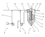
図1に示した実施形態例において、ろ過装置1の本体は、筒状の胴部4と逆コーン状の底部5とからなる槽に、前記ろ材を充填してろ過床6とし、原水供給管7により供給される原水を、ろ過床の下部に設けた原水分配管8から供給して上向きにろ過床6内を通過させ、ろ過した処理水は上部から集水トラフ9にオーバフローさせ処理水排出管10を通して系外に導出するものである。一方、ろ材は、ろ過床6からコーン状部分5へと下降し、最下部のコーン頂点にあたる部分の空気吹込管11の先端12から吹込まれる空気に伴われ、周辺の水とともエアリフト管13を上昇しながら空気と水とで混合逆洗される。さらにろ材は、分離器14で水とは分離され、ろ材はサンドウォッシャー15を下降し上昇するろ過水と対向流で逆洗され、再びろ過床6上部へと戻される。ろ材と分離したエアリフト管13およびサンドウォッシャー15からの逆洗水は、多量の生物体を含んで酸化還元電位が低下しており、逆洗排水管16によりろ過装置1外に導出される。本発明が比較的小量の原水の脱窒・SS除去処理を対象とする場合には、単一ろ過槽を使用するが、大量の原水を処理する際には複数の単位ろ過槽(モジュール)をまとめ、マルチモジュール型として利用することができる。
【0008】
ろ過装置1に供給される原水は、あらかじめ水素供与体供給装置2により、本実施形態例では原水供給管7において水素供与体供給管17から水素供与体を添加される。水素供与体としては、菌種に応じてアルコール類、カルボン酸類等の有機物質が考えられるが、菌種が適合すれば実用上メタノールが好適である。必要な添加量は、一般には
メタノール濃度(mg/l)=2.47×NO3 −N(mg/l)+1.53×NO2 −N(mg/l)+0.87×DO(mg/l)
で表される。通常、硝酸性窒素の3倍のメタノール濃度で添加すればよい。また、加えてリンを除去したい場合には、凝集剤としてポリ塩化アルミニウムや塩化第2鉄を添加すればよい。
【0009】
本発明では、さらにろ過装置1の逆洗排水を逆洗排水返送管18を経て原水に添加する。すなわち、ろ材洗浄後、ろ過装置1外に排出された逆洗排水は、逆洗排水管16を経て排出されるが、そのうちの一部が逆洗排水返送管18を経て原水供給側に返送され、本実施形態例では原水供給管7において原水に混合される。逆洗排水の返送方法は逆洗排水返送用ポンプ19を用い、直接逆洗排水をポンプアップする方法、一旦受槽または水槽を設け、そこからポンプアップする方式、原水ポンプによるエゼクタ方式等を採用することができる。また、前記の添加物の原水への添加順、原水との混合手段等に特別の制限はない。
【0010】
さて、前記の水素供与体および逆洗排水を含む原水は、原水供給管7を経て原水分配管8からろ過床6下部に送入される。原水がろ過床6内を上昇する間に、添加された逆洗排水中の脱窒菌(生物)は、ろ材に付着、保持され、脱窒に必要な水素を水素供与体から得て、硝酸性窒素を生物的に分解、脱窒して増殖する。他方原水中のSSはろ材によりろ過除去され、目的の処理が遂行される。ろ材の逆洗は処理工程と並行して連続的に行われる。ろ過装置1底部近くの生物を多く保持したろ材は、空気吹込管11から送られた空気によって水とともにエアリフト管13に吸入されて管内を上昇する過程で同伴する水と空気とにより逆洗され、分離器14内に排出されて水及び空気と分離され、さらにサンドウォッシャー15を下降する過程で上昇水により逆洗される。前記の逆洗の過程でSS及びろ材に付着していた生物は水側に移行し、ろ材はろ過性能を回復する。排出される逆洗排水は生物量が豊富で酸化還元電位が低い。本発明においてはその一部が、逆洗排水返送装置により原水中に返送される。原水に対する返送逆洗排水の容積割合(返送率)は、1〜150%、好ましくは5〜100%である。返送率は、原水の性状により逆洗排水中の生物量等が異なるために、対象水ごとに最適値が異なる。
【0011】
【発明の効果】
本発明に係る窒素及び懸濁物質の連続同時除去方法及びそのシステムにおいては 、ろ過操作とろ材の逆洗操作とが並行して連続的に進められるので、生物膜の発生 によるろ過床の閉塞がなく、長期連続操業を実施できる。また、ろ過床内で増殖し た生物が豊富に含まれ酸化還元電位の低い逆洗排水が原水中に返送されるので、原 水がろ過床に到達するまでの間にも脱窒が進行し、さらにろ過床においても生物量 が増加して脱窒速度を増大する効果がある。さらに逆洗排水中の生物をろ床内に返 送・保持できるため、生物の馴致期間を短縮でき、また逆洗排水中のBODを水素 供与体として利用できることから、添加する水素供与体量を低減するすることがで きる。
【図面の簡単な説明】
【図1】本発明の一実施形態例を示すフローシート
【符号の説明】
1:移床式上向流ろ過装置 2:水素供与体供給装置
3:逆洗排水返送装置 4:ろ過装置の本体胴部 5:ろ過装置本体底部
6:ろ過床 7:原水供給管 8:原水分配管 9:集水トラフ
10:処理水排出管 11:空気吹込管 12:空気吹込管先端
13:エアリフト管 14:分離器 15:サンドウォッシャー
16:逆洗排水管 17:水素供与体供給管 18:逆洗排水返送管
19:逆洗排水返送用ポンプ[0001]
BACKGROUND OF THE INVENTION
The present invention supplies secondary treated water such as domestic wastewater such as sewage and human waste, industrial wastewater, landfill leachate, etc. , particularly secondary treated water of sewage to a moving bed type upflow filtration device, and nitrogen mixed therein. The present invention relates to a continuous simultaneous removal method and removal system for nitrogen and nitrogen components and suspended solids in sewage secondary treated water that biologically decomposes components and filters suspended solids.
[0002]
[Prior art]
In order to remove nitrogen components contained in wastewater such as sewage, a method of biologically decomposing and removing wastewater by causing it to act sequentially on nitrifying bacteria and denitrifying bacteria is used. Typical nitrogen removal processes include nitrification and denitrification systems that separate and treat nitrification and denitrification functions, including secondary treatment of wastewater, and denitrification and nitrification systems that circulate nitrification liquid to the denitrification process. Process. In addition, in order to treat secondary treated water of sewage, a fixed bed biofilm filtration device is newly installed after the existing treatment device, and methanol is added to the secondary treated water as a hydrogen donor for denitrification treatment. The method is also widely implemented.
[0003]
[Problems to be solved by the invention]
By the way, the above-mentioned nitrogen component removal process can keep the operating cost low, but the nitrogen removal rate is not so high for a long treatment residence time, or the nitrogen removal rate is high but an excessive biofilm is formed and blocked. It is easy and easy, both when the peeled biofilm is mixed into the treated water, and there is no clogging of the filter bed, but the amount of retained organism is small. On the other hand, the moving bed type upflow sand filter is difficult to retain organisms in the filter bed and cannot sufficiently remove nitrogen at a normal filtration rate. As a result of studying an efficient denitrification method and a system for removing suspended substances at the same time mainly for secondary treated water of sewage, the present inventor was able to complete the present invention.
[0004]
[Means for Solving the Problems]
The gist of the present invention will be described with reference to the drawings. The present invention relates to a moving bed type upflow filtration apparatus having a continuous backwashing function of a filter medium to which a hydrogen donor is added using sewage secondary treated water containing nitrogen compounds and suspended substances (SS) as feed treated water. by then fed further added to return the portion of the backwash waste water discharged from the
[0005]
DETAILED DESCRIPTION OF THE INVENTION
The present invention will be specifically described with reference to the drawings and embodiments. FIG. 1 is a flow sheet showing an embodiment of the present invention. Hereinafter, the sewage secondary treated water to be supplied treated water in the present invention is referred to as “raw water”.
[0006]
First, the moving bed type upward
[0007]
In the embodiment shown in FIG. 1, the main body of the
[0008]
The raw water supplied to the
It is represented by Usually, it may be added at a methanol concentration three times that of nitrate nitrogen. In addition, when it is desired to remove phosphorus, polyaluminum chloride or ferric chloride may be added as a flocculant.
[0009]
In the present invention, the backwash wastewater from the
[0010]
The raw water containing the hydrogen donor and the backwash waste water is sent from the raw water pipe 8 to the lower part of the filtration bed 6 through the raw water supply pipe 7. While the raw water rises in the filter bed 6, the added denitrifying bacteria (biological matter) in the backwash wastewater adheres to and is retained on the filter medium, and obtains hydrogen necessary for denitrification from the hydrogen donor. Nitrogen is biologically decomposed and denitrified to grow. On the other hand, the SS in the raw water is filtered and removed by the filter medium, and the target treatment is performed. The backwashing of the filter medium is continuously performed in parallel with the treatment process. The filter medium holding a large amount of organisms near the bottom of the
[0011]
【The invention's effect】
In the continuous simultaneous removal method of nitrogen and suspended solids and the system thereof according to the present invention, the filtration operation and the backwashing operation of the filter medium are continuously performed in parallel, so that the filtration bed is blocked due to the generation of a biofilm. Long-term continuous operation. In addition, since backwash wastewater containing abundant organisms grown in the filter bed and having a low oxidation-reduction potential is returned to the raw water, denitrification proceeds until the raw water reaches the filter bed. In addition, the amount of biomass in the filter bed is also increased, which has the effect of increasing the denitrification rate. Furthermore, because living organisms in backwash wastewater can be returned and retained in the filter bed, the acclimatization period of organisms can be shortened, and BOD in backwash wastewater can be used as a hydrogen donor, so the amount of hydrogen donor to be added can be reduced. Can be reduced.
[Brief description of the drawings]
FIG. 1 is a flow sheet showing an embodiment of the present invention.
1: Transfer bed type upflow filtration device 2: Hydrogen donor supply device 3: Backwash drainage return device 4: Body body of filtration device 5: Bottom portion of filtration device body 6: Filtration bed 7: Raw water supply pipe 8: Raw material Moisture piping 9: Catchment trough 10: Treated water discharge pipe 11: Air blowing pipe 12: Air blowing pipe tip 13: Air lift pipe 14: Separator 15: Sand washer 16: Backwash drain pipe 17: Hydrogen donor supply pipe 18 : Backwash drainage return pipe 19: Backwash drainage return pump
Claims (3)
Priority Applications (1)
| Application Number | Priority Date | Filing Date | Title |
|---|---|---|---|
| JP24933598A JP3607088B2 (en) | 1998-09-03 | 1998-09-03 | Method and system for continuous simultaneous removal of nitrogen and suspended solids from wastewater |
Applications Claiming Priority (1)
| Application Number | Priority Date | Filing Date | Title |
|---|---|---|---|
| JP24933598A JP3607088B2 (en) | 1998-09-03 | 1998-09-03 | Method and system for continuous simultaneous removal of nitrogen and suspended solids from wastewater |
Publications (2)
| Publication Number | Publication Date |
|---|---|
| JP2000070990A JP2000070990A (en) | 2000-03-07 |
| JP3607088B2 true JP3607088B2 (en) | 2005-01-05 |
Family
ID=17191496
Family Applications (1)
| Application Number | Title | Priority Date | Filing Date |
|---|---|---|---|
| JP24933598A Expired - Lifetime JP3607088B2 (en) | 1998-09-03 | 1998-09-03 | Method and system for continuous simultaneous removal of nitrogen and suspended solids from wastewater |
Country Status (1)
| Country | Link |
|---|---|
| JP (1) | JP3607088B2 (en) |
Cited By (1)
| Publication number | Priority date | Publication date | Assignee | Title |
|---|---|---|---|---|
| CN102849848A (en) * | 2012-09-26 | 2013-01-02 | 北京市环境保护科学研究院 | Inner circulation bio-filter reactor and sewage treatment method |
Families Citing this family (5)
| Publication number | Priority date | Publication date | Assignee | Title |
|---|---|---|---|---|
| EP1016633A1 (en) * | 1998-12-29 | 2000-07-05 | Pâques Bio Systems B.V. | Process for the treatment of waste water containing heavy metals |
| JP2006272082A (en) * | 2005-03-28 | 2006-10-12 | Takuma Co Ltd | Ultrahigh-level method for treating water and water treatment system to be used therein |
| JP2013027821A (en) * | 2011-07-28 | 2013-02-07 | Takuma Co Ltd | Sand filtration device, and method for producing filter sand therefor |
| US10017406B2 (en) | 2013-10-02 | 2018-07-10 | John H. Reid | Upflow continuous backwash filter |
| CN106379993A (en) * | 2016-10-26 | 2017-02-08 | 桂林理工大学 | Continuous back washing denitrification deep bed filter device for treating tail water from sewage plant |
-
1998
- 1998-09-03 JP JP24933598A patent/JP3607088B2/en not_active Expired - Lifetime
Cited By (2)
| Publication number | Priority date | Publication date | Assignee | Title |
|---|---|---|---|---|
| CN102849848A (en) * | 2012-09-26 | 2013-01-02 | 北京市环境保护科学研究院 | Inner circulation bio-filter reactor and sewage treatment method |
| CN102849848B (en) * | 2012-09-26 | 2014-03-05 | 北京市环境保护科学研究院 | Internal circulation biological filter reactor and sewage treatment method |
Also Published As
| Publication number | Publication date |
|---|---|
| JP2000070990A (en) | 2000-03-07 |
Similar Documents
| Publication | Publication Date | Title |
|---|---|---|
| AU2002301606B2 (en) | Batch Style Wastewater Treatment Apparatus Using Biological Filtering Process and Wastewater Treatment Method Using The Same | |
| JP2005279447A (en) | Water treatment method and apparatus | |
| US4159945A (en) | Method for denitrification of treated sewage | |
| KR102171918B1 (en) | Recycling and water quality purification treatment system of livestock manure | |
| US7547394B2 (en) | Wastewater treatment with aerobic granules | |
| JP3607088B2 (en) | Method and system for continuous simultaneous removal of nitrogen and suspended solids from wastewater | |
| JP5557301B1 (en) | Wastewater purification system | |
| KR100698522B1 (en) | Livestock manure purification system using microorganisms | |
| KR100336484B1 (en) | A Soil Clothing-Style Contact Oxidation Apparatus with Recycle of Nitrified Liquid and Contact Oxidation Method of Using the Same | |
| JP4017331B2 (en) | Septic tank | |
| JP2003010871A (en) | Sewage treatment apparatus and operating method thereof | |
| KR100583904B1 (en) | Wastewater Advanced Treatment System | |
| RU2270809C2 (en) | Integrated waste water treatment plant | |
| CN101417847A (en) | Domestic living waste water treater | |
| JP2002346591A (en) | Sewage treatment apparatus and operating method thereof | |
| JP2574649B2 (en) | Aerobic livestock waste septic tank | |
| KR20190004168A (en) | A waste water of stock raising disposal plant | |
| KR200171727Y1 (en) | Processing system for excretions of animals | |
| JP2004097926A (en) | Water treatment method and water treatment equipment | |
| JP4403704B2 (en) | Biofilm filtration apparatus and treatment method | |
| KR200337564Y1 (en) | High intergated Biological Nutrient Removal System | |
| JP2565429B2 (en) | Method and apparatus for biological nitrification denitrification of organic wastewater | |
| JP2520798B2 (en) | Method and apparatus for biological dephosphorization of organic wastewater | |
| JP3919455B2 (en) | Advanced denitrification method for waste water | |
| RU36657U1 (en) | UNIT OF BIOLOGICAL CLEANING OF HOUSEHOLD WASTE WATER |
Legal Events
| Date | Code | Title | Description |
|---|---|---|---|
| A521 | Written amendment |
Free format text: JAPANESE INTERMEDIATE CODE: A523 Effective date: 20031222 |
|
| A131 | Notification of reasons for refusal |
Free format text: JAPANESE INTERMEDIATE CODE: A131 Effective date: 20040224 |
|
| A521 | Written amendment |
Free format text: JAPANESE INTERMEDIATE CODE: A523 Effective date: 20040423 |
|
| A02 | Decision of refusal |
Free format text: JAPANESE INTERMEDIATE CODE: A02 Effective date: 20040622 |
|
| A521 | Written amendment |
Free format text: JAPANESE INTERMEDIATE CODE: A523 Effective date: 20040726 |
|
| A911 | Transfer to examiner for re-examination before appeal (zenchi) |
Free format text: JAPANESE INTERMEDIATE CODE: A911 Effective date: 20040830 |
|
| TRDD | Decision of grant or rejection written | ||
| A01 | Written decision to grant a patent or to grant a registration (utility model) |
Free format text: JAPANESE INTERMEDIATE CODE: A01 Effective date: 20041005 |
|
| A61 | First payment of annual fees (during grant procedure) |
Free format text: JAPANESE INTERMEDIATE CODE: A61 Effective date: 20041006 |
|
| R150 | Certificate of patent or registration of utility model |
Free format text: JAPANESE INTERMEDIATE CODE: R150 |
|
| FPAY | Renewal fee payment (event date is renewal date of database) |
Free format text: PAYMENT UNTIL: 20071015 Year of fee payment: 3 |
|
| FPAY | Renewal fee payment (event date is renewal date of database) |
Free format text: PAYMENT UNTIL: 20081015 Year of fee payment: 4 |
|
| FPAY | Renewal fee payment (event date is renewal date of database) |
Free format text: PAYMENT UNTIL: 20081015 Year of fee payment: 4 |
|
| FPAY | Renewal fee payment (event date is renewal date of database) |
Free format text: PAYMENT UNTIL: 20091015 Year of fee payment: 5 |
|
| FPAY | Renewal fee payment (event date is renewal date of database) |
Free format text: PAYMENT UNTIL: 20101015 Year of fee payment: 6 |
|
| FPAY | Renewal fee payment (event date is renewal date of database) |
Free format text: PAYMENT UNTIL: 20111015 Year of fee payment: 7 |
|
| FPAY | Renewal fee payment (event date is renewal date of database) |
Free format text: PAYMENT UNTIL: 20111015 Year of fee payment: 7 |
|
| FPAY | Renewal fee payment (event date is renewal date of database) |
Free format text: PAYMENT UNTIL: 20121015 Year of fee payment: 8 |
|
| FPAY | Renewal fee payment (event date is renewal date of database) |
Free format text: PAYMENT UNTIL: 20121015 Year of fee payment: 8 |
|
| FPAY | Renewal fee payment (event date is renewal date of database) |
Free format text: PAYMENT UNTIL: 20131015 Year of fee payment: 9 |
|
| R250 | Receipt of annual fees |
Free format text: JAPANESE INTERMEDIATE CODE: R250 |
|
| R250 | Receipt of annual fees |
Free format text: JAPANESE INTERMEDIATE CODE: R250 |
|
| R250 | Receipt of annual fees |
Free format text: JAPANESE INTERMEDIATE CODE: R250 |
|
| R250 | Receipt of annual fees |
Free format text: JAPANESE INTERMEDIATE CODE: R250 |
|
| R250 | Receipt of annual fees |
Free format text: JAPANESE INTERMEDIATE CODE: R250 |
|
| EXPY | Cancellation because of completion of term |