JP3607078B2 - Engine supercharging pressure control device - Google Patents
Engine supercharging pressure control device Download PDFInfo
- Publication number
- JP3607078B2 JP3607078B2 JP15477898A JP15477898A JP3607078B2 JP 3607078 B2 JP3607078 B2 JP 3607078B2 JP 15477898 A JP15477898 A JP 15477898A JP 15477898 A JP15477898 A JP 15477898A JP 3607078 B2 JP3607078 B2 JP 3607078B2
- Authority
- JP
- Japan
- Prior art keywords
- target
- control
- supercharging pressure
- control amount
- engine
- Prior art date
- Legal status (The legal status is an assumption and is not a legal conclusion. Google has not performed a legal analysis and makes no representation as to the accuracy of the status listed.)
- Expired - Lifetime
Links
Images


Classifications
-
- Y—GENERAL TAGGING OF NEW TECHNOLOGICAL DEVELOPMENTS; GENERAL TAGGING OF CROSS-SECTIONAL TECHNOLOGIES SPANNING OVER SEVERAL SECTIONS OF THE IPC; TECHNICAL SUBJECTS COVERED BY FORMER USPC CROSS-REFERENCE ART COLLECTIONS [XRACs] AND DIGESTS
- Y02—TECHNOLOGIES OR APPLICATIONS FOR MITIGATION OR ADAPTATION AGAINST CLIMATE CHANGE
- Y02T—CLIMATE CHANGE MITIGATION TECHNOLOGIES RELATED TO TRANSPORTATION
- Y02T10/00—Road transport of goods or passengers
- Y02T10/10—Internal combustion engine [ICE] based vehicles
- Y02T10/12—Improving ICE efficiencies
Landscapes
- Supercharger (AREA)
Description
【0001】
【発明の属する技術分野】
本発明は、ターボチャージャ等の過給機を具備するエンジンの過給圧を制御する過給圧制御装置に関する。
【0002】
【従来の技術】
従来、ターボチャージャ付エンジンでは、ターボチャージャのタービン側に、排気の一部を逃がすウエストゲート弁を設け、ウエストゲート弁の開度を電子制御して過給圧を制御している。
【0003】
過給圧の制御方式としては、運転状態に応じて設定される目標過給圧と実過給圧との偏差から算定される目標制御量に基づく制御を行うフィードバック方式が一般的である。然し、フィードバック制御では、過給圧の上昇過渡期に当初過給圧の上昇が遅れて途中から急激に上昇した場合、過給圧の上昇遅れ期間で追いかけ制御し過ぎてしまい、過給圧が目標過給圧に対し大きくオーバーシュートしてノッキングを生じ易くなる。
【0004】
かかる不具合を解消するため、従来、特開平2−176117号公報により、過給圧の制御方式として、上記フィードバック制御と、エンジンの運転状態に応じて設定される基本制御量に基づくオープンループ制御とを併用し、エンジン負荷の増加等で過給圧の上昇が必要になったとき、過給圧の上昇過渡期はオープンループ制御を実行し、過給圧が目標過給圧に上昇したところでフィードバック制御を実行するようにしたものも知られている。
【0005】
【発明が解決しようとする課題】
上記従来例では、実過給圧が目標過給圧に上昇するまでオープンループ制御が実行され、過給圧の上昇過渡期におけるフィードバック方式での追いかけ制御のし過ぎによるオーバーシュートが防止される。然し、オープンループ制御の実行中にエンジン負荷の急増等で基本制御量が急増すると、過給圧が急上昇して目標過給圧に対し大きくオーバーシュートしてしまう。
【0006】
この場合、基本制御量の上限値を定め、実際の制御量を上限値以下に制限することも考えられるが、上限値を低く設定すると過給圧の上昇が遅れて加速性が損われ、上限値を高く設定するとオーバーシュートを生じ易くなり、オーバーシュートの防止と加速性との両立が困難になる。
【0007】
本発明は、以上の点に鑑み、加速性を損うことなくオーバーシュートを防止できるようにした過給圧制御装置を提供することを課題としている。
【0008】
【課題を解決するための手段】
上記課題を解決すべく、本発明は、過給機付エンジンの過給圧を、エンジンの運転状態に応じて設定される基本制御量に基づくオープンループ制御と、エンジンの運転状態に応じて設定される目標過給圧と実過給圧との偏差から算定される目標制御量に基づくフィードバック制御とによって制御するエンジンの過給圧制御装置であって、実過給圧が目標過給圧に上昇するまでオープンループ制御を実行するものにおいて、オープンループ制御の実行時に前記基本制御量と前記目標制御量とを比較する第1比較手段と、該第1比較手段により基本制御量が目標制御量より大きいと判別されたときに、過給圧の制御に用いる制御量を基本制御量から目標制御量に置換する第1置換手段と、を備えることを特徴とする。
【0009】
本発明によれば、オープンループ制御の実行中に基本制御量が急増して目標制御量より大きくなると、実際の制御量が基本制御量から目標制御量に置換され、制御方式が実質的にフィードバック制御に移行する。従って、基本制御量が急増したときは、実過給圧が目標過給圧に上昇する前にフィードバック制御が実行され、過不足のない過給圧が得られ、オーバーシュートが防止されると共に加速性も確保される。
【0010】
ところで、フィードバック制御の開始後は、フィードバック制御とオープンループ制御との切換ハンチングを防止するため、一般に、実過給圧が目標過給圧よりも所定のヒステリシス量分だけ低く設定した下限目標過給圧を下回るまでフィードバック制御を継続しているが、フィードバック制御中に、実過給圧の一時的な減少で実過給圧が下限目標過給圧を下回り、オープンループ制御に移行してしまうことがある。この場合、フィードバック制御の開始後、エンジン負荷を軽減する操作が行われない限りフィードバック制御を継続するフィードバック継続手段を備えておけば、実過給圧の一時的な減少によってもフィードバック制御が継続されて、安定した過給圧の制御が行われる。一方、これでは、フィードバック制御中に、エンジン負荷の急増等で目標過給圧が実過給圧をかなり上回ってもフィードバック制御が続行される。ここで、目標制御量は実過給圧が目標過給圧に段階的に近付くように設定されるから、目標過給圧が急増した場合、実過給圧が目標過給圧に到達するまでに時間がかかる。この場合、フィードバック制御の実行中に、目標過給圧が実過給圧よりも所定値以上大きくなった時、前記基本制御量と前記目標制御量とを比較する第2比較手段と、該第2比較手段により基本制御量が目標制御量よりも大きいと判定されたときに、過給圧の制御に用いる制御量を目標制御量から基本制御量に置換する第2置換手段と、を備えておけば、目標過給圧の急増時には、目標制御量と基本制御量のうち大きい方が実際の制御量として選択されることになり、実過給圧が目標過給圧に速やかに到達し、加速性能が向上する。ここで、前記所定値は、実過給圧を目標過給圧に上昇させるのにフィードバック制御だけでは加速性に悪影響を及ぼすような応答遅れを生ずる目標過給圧と実過給圧との偏差の下限値に合わせて設定される。
【0011】
尚、後記する実施形態において、上記第1比較手段に相当するのは図7のS12−19のステップであり、上記第1置換手段に相当するのはS12−19のステップからS12−17のステップに至る処理である。また、上記フィードバック継続手段に相当するのは図6のS11−14のステップからS11−10のステップに至る処理であり、上記第2比較手段に相当するのは図7のS12−18のステップであり、上記第2置換手段に相当するのはS12−18のステップからS12−21のステップに至る処理である。
【0012】
【発明の実施の形態】
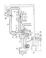
図1は過給機たるターボチャージャ1付きのエンジンを示しており、エンジン本体2の吸気ポート2aに連なる吸気通路3にターボチャージャ1のコンプレッサ1aを介設すると共に、エンジン本体2の排気ポート2bに連なる排気通路4にターボチャージャ1のタービン1bを介設している。尚、吸気通路3のコンプレッサ1a上流側にはエアクリーナ5が設けられ、コンプレッサ1a下流側にはインタークーラ6とスロットルバルブ7と燃料噴射弁8とが設けられている。
【0013】
タービン1bには排気の一部を逃がすウエストゲート弁1cが設けられており、ウエストゲート弁1cの開度に応じてコンプレッサ1a下流側の吸気通路部分の過給圧が変化する。ウエストゲート弁1cは内部にダイヤフラム9aを有するアクチュエータ9に連結され、アクチュエータ9内のばね9bで閉じ側に付勢されている。そして、ウエストゲート弁1cを開き側に押圧するアクチュエータ9内の圧力室9cをオリフィス10a付きの連通路10を介してコンプレッサ1a下流側の吸気通路部分に連通させると共に、連通路10を電磁弁11を介設したリーク通路12を介してコンプレッサ1a上流側の吸気通路部分に連通させ、圧力室9cに入力される過給圧を電磁弁11を介してリークして圧力室9cの内圧を制御し、ウエストゲート弁1cの開度を制御し得るようにしている。
【0014】
電磁弁11は電子制御回路(以下ECUと記す)13によりデューティ制御されるようになっており、電磁弁11の駆動信号のデューティ比が大きくなる程電磁弁11の開度が増して圧力室9cの内圧が低下し、ウエストゲート弁1cの開度が減少して過給圧が高くなる。
【0015】
ECU13には、エンジンの回転数NEを検出するセンサ14と、コンプレッサ1a下流側の吸気通路部分の過給圧PBAを検出するセンサ15と、スロットル開度THを検出するセンサ16と、エンジン冷却水の水温TWを検出するセンサ17と、吸気温TAを検出するセンサ18と、ブレーキペダルの踏込みを検出するブレーキスイッチ19とからの信号が入力されており、これら信号に基づいて制御量たる駆動信号の出力デューティ比WCMDを演算する。尚、本実施形態ではPBAセンサ15をスロットルバルブ7の下流側に設けているが、上流側に設けても良い。
【0016】
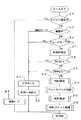
ECU13で行う処理の詳細は図2に示す通りであり、先ず、S1のステップでエンジンが停止中か否かを判別し、エンジン停止中であればS2のステップに進んで出力デューティ比を0に設定し、即ち、駆動信号の出力を停止し、1回の演算処理を終了する。エンジン停止中でなければS3のステップでエンジンが始動中か否かを判別し、始動中でなければS4のステップで車載機器の故障によるフェールセーフ中か否かを判別する。始動中やフェールセーフ中であれば、S5のステップでフィードバック判定フラグFTBFBを0にリセットした後、S6のステップでWCMDを所定値WCMDOに設定し、1回の処理を終了する。尚、WCMDOは、電磁弁11が実質的に閉弁状態に維持されるデューティ比の上限値に設定されており、デューティ比がWCMDOより僅かでも大きくなると電磁弁11が開き始める。
【0017】
S4のステップでフェールセーフ中でないと判定されると、S7のステップで後記詳述する基本制御量たる基本デューティ比WCMDBSの算出処理を実行した後、S8のステップでアクセル・ブレーキ同時踏み判定フラグFATSAが1にセットされているか否かを判別する。FATSAは、スロットル開度THとブレーキスイッチ19とに基づいてアクセルペダルとブレーキペダルとが同時に踏み込まれていると判断したときに1にセットされるフラグであり、FATSA≠1であればS9のステップに進み、過回転によるフューエルカット時に1にセットされるフューエルカット判定フラグFNHFCTCが1にセットされているか否かを判別する。FATSA=1やFNHFCTC=1であれば、始動中やフェールセーフ中と同様にS5以下のステップに進み、WCMDはWCMDOに設定され、これらの状態での過給によるエンジンの無用の出力アップが防止される。
【0018】
S9のステップでFNHFCTC≠1と判定されると、S10のステップで後記詳述する目標過給圧POBJの算出処理を実行すると共に、S11のステップで後記詳述するフィードバック判定処理を実行し、次にS12のステップで後記詳述する出力デューティ比WCMDの算出処理を実行し、最後にS13のステップに進み、WCMDが所定の上限値以上や所定の下限値以下のときにWCMDをこれら上限値や下限値に置き換えるリミット処理を実行し、1回の処理を終了する。
【0019】
上記基本デューティ比WCMDBSは、エンジンの各回転域においてエンジン負荷の増減に応じて過給圧が増減されるように設定されるもので、エンジン回転数NEとスロットル開度THとに応じたWCMDBSの値がWCMDBSマップとしてECU13に格納されている。上記S7のステップにおけるWCMDBSの算出処理の詳細は図3に示す通りであり、先ず、S7−1のステップにおいて、後記する如く更新されるスロットル開度の値THWBSと今回検出されたスロットル開度THとの偏差の絶対値が所定値DTHWBS(例えば3゜)より大きいか否かを判別し、大きければS7−2のステップでTHWBSをTHに更新し、小さければTHWBSを更新せずにS7−3のステップに進み、今回検出されたエンジン回転数NEとTHWBSとに応じた基本デューティ比WCMDBSをWCMDBSマップから検索する。これによれば、スロットル開度の変化が僅かな場合にはWCMDBSが変化せず、安定走行が行なえ、スロットル開度が急に変化した場合にはその変化に応じてWCMDBSが変化し、加速性能及び減速性能が向上する。
【0020】
上記S10のステップにおけるPOBJの算出処理の詳細は図4に示す通りであり、先ず、S10−1のステップで後記詳述する基本目標過給圧POBJMの算出処理を実行し、次にS10−2のステップでフィードバック判定フラグFTBFBが1にセットされているか否かを判別し、FTBFB≠1であれば、S10−3のステップで目標過給圧POBJをPOBJMに更新し、1回の処理を終了する。FTBFB=1であれば、S10−4のステップに進んで前回算出されたPOBJが今回算出されたPOBJMと等しいか否かを判別し、POBJ≠POBJMであれば、S10−5のステップでPOBJとPOBJMとを比較し、POBJ<POBJMであれば、S10−6のステップでPOBJをPOBJMに更新すると共に、S10−7のステップでECU13に内蔵する第1の減算式タイマの残り時間tm1を所定時間tmA(例えば0.2秒)にセットし、1回の処理を終了する。一方、POBJ>POBJMであれば、S10−8のステップでtm1が0になったか否かを判別し、tm1≠0であればそのまま1回の処理を終了し、tm1=0になったときS10−6以下のステップに進み、POBJをPOBJMに更新すると共にtm1を所定時間tmAにセットする。また、S10−4のステップでPOBJ=POBJMと判定されたときは、POBJを更新せずにS10−7のステップに進み、tm1を所定時間tmAにセットする。かくて、POBJ>POBJMになっても所定時間tmAが経過するまではPOBJが更新されないためハンチングが防止され、また、POBJ<POBJMになったときはPOBJが直ちに更新されるためドライバビリティが向上する。
【0021】
上記S10−1のステップにおけるPOBJMの算出処理の詳細は図5(A)に示す通りである。POBJMは、エンジンの各回転域でターボチャージャの最適能力を引き出し得るようエンジン回転数NEに応じて図5(B)に示す如く設定される過給圧PNGRHと、吸気充填効率とノッキング回避とを最適に両立し得るようエンジン回転数NEと吸気温TAとに応じて設定される過給圧PLMTTAと、エンジンやターボチャージャの耐久性を良好に保持し得るよう冷却水温TWに応じて設定される過給圧PLMTTWとを用いて算出しており、先ず、S10−1のステップでPNGRH,PLMTTA、PLMTTWを検索し、次に、S10−1−2のステップでPOBJMをPNGRHに設定する。次に、S10−1−3のステップでPLMTTAとPLMTTWとを比較し、PLMTTA≧PLMTTWであればS10−1−4のステップで過給圧のリミット値PLMTをPLMTTWに設定し、PLMTTA<PLMTTWであればS10−1−5でPLMTをPLMTTAに設定する。次に、S10−1−6のステップでPOBJM、即ち、S10−1−2のステップでPOBJMとして設定されたPNGRHとPLMTとを比較し、POBJM>PLMTであれば、S10−1−7のステップでPOBJMをPLMTに設定し直し、POBJM≦PLMTであればPOBJMを設定し直さずに処理を終了する。かくて、POBJMはPNGRHとPLMTTAとPLMTTWとのうちの最小圧に設定され、このPOBJMが最終的に目標過給圧POBJに設定されるため、最適能力の引き出し、吸気充填効率とノッキング回避との両立、耐久性の確保という各課題を解決可能な必要最大の過給圧にPOBJを簡単、且つ、正確に設定できる。
【0022】
上記S11のステップにおけるフィードバック判定処理の詳細は図6に示す通りであり、先ず、S11−1のステップで目標過給圧POBJから所定のヒステリシス量DFBPBLを減算した値を下限目標過給圧POBJLとして設定する。次に、S11−2のステップに進み、エンジンの各回転域において過給圧がインターセプト(非過給状態から過給状態への移行点)を充分越え、且つ、過給圧の安定したフィードバック制御が可能か否かをスロットル開度THに基づいて判別するためのエンジン回転数NEに応じた判別基準値THTBFBを検索する。次に、S11−3のステップに進み、WCMDBSの算出処理で設定された上記THWBSとTHTBFBとを比較し、THWBS≧THTBFBであれば、S11−4のステップで今回のスロットル開度と前回のスロットル開度との偏差DTHが所定値DTHTBFB以下か否かを判別する。DTHTBFBは運転者の加速の意図をスロットル開度の変化に基づいて判断するための値であり、DTH≦DTHTBFBのとき、即ち、運転者が加速を意図していないときは、S11−5のステップでECU13に内蔵する第2の減算式タイマの残り時間tm2が0になったか否かを判別し、tm2=0になるまではそのまま処理を終了し、tm2=0になったときにS11−7のステップに進む。また、DTH>DTHTBFBのとき、即ち、運転者が加速を意図しているときは、S11−6のステップでtm2を0にリセットしてS11−7のステップに進む。
【0023】
S11−7のステップではフィードバック判定フラグFTBFBが1にセットされているか否かを判別し、FTBFB=0であれば、S11−8のステップで実過給圧PBAが目標過給圧POBJ以上であるか否をを判別し、PBA≧POBJLであれば、S11−9のステップでtm2を所定時間tmB(例えば1秒)にセットすると共に、S11−10のステップでFTBFBを1にセットし、1回の判別処理を終了する。PBA<POBJであれば、S11−11のステップで実過給圧PBAが下限目標過給圧POBJL以上であるか否かを判別し、PBA<POBJLであれば、S11−12のステップでECU13に内蔵する第3の減算式タイマの残り時間tm3を所定時間tmC(例えば0.5秒)にセットし、PBA≧POBJLであれば、S11−13のステップでtm3が0になったか否かを判別し、tm3=0になったときにS11−9以下のステップに進む。次回はS11−7のステップでFTBFB=1と判定され、この場合はS11−14のステップに進み、THWBSの今回の値THWBS(n)と前回の値THWBS(n−1)とを比較する。そして、THWBS(n)<THWBS(n−1)のとき、即ち、スロットル開度(エンジン負荷)を減少するアクセル戻し操作が行われているときにS11−15のステップに進み、PBAがPOBJL以上か否かを判別し、PBA≧POBJLであればS11−10のステップに進んでFTBFB=1に維持し、PBA<POBJLになったとき、S11−16のステップでtm2をtmBにセットすると共に、S11−17のステップでFTBFBを0にリセットする。また、S11−3のステップでTHWBS<THTBFBと判定されたときや、S11−11のステップでPBA<POBJLと判定されたときや、PBA≧POBJLであってもS11−13のステップでtm3≠0と判定されたときはS11−17のステップに進みFTBFBを0にリセットする。一方、S11−14のステップでTHWBS(n)≧THWBS(n−1)と判定されたときは、S11−10のステップに進んでFTBFB=1に維持する。
【0024】
かくて、THWBS≧THTBFBであって、且つ、PBA≧POBJのとき、または、PBAが所定時間tmC継続してPOBJL以上のときにFTBFBが1にセットされ、その後はTHWBS≧THTBFBである限り、アクセル戻し操作(エンジン負荷の軽減操作)が行われ、且つ、PBA<POBJLになるまでFTBFB=1に維持され、PBAの微小変化によるFTBFBの切換ハンチングが防止される。更に、アクセル戻し操作が行われない限り、実過給圧PBAの一時的な減少でPBA<POBJLになってもFTBFB=1に維持され、フィードバック制御が続行されて、安定した過給圧の制御が行われる。
【0025】
また、DTH≦DTHTBFBとなる非加速時は、PBA≧POBJ、または、所定時間tmC継続してPBA≧POBJLになってFTBFBが0から1に切換えられ、或いは、PBA<POBJLになってFTBFBが1から0に切換えられてから所定時間tmBが経過するまでFTBFBの切換えが阻止され、一方、DTH>DTHTBFBとなる加速時は直ちにFTBTBの切換えが可能となり、ハンチング防止と加速性向上との両立が図られる。
【0026】
上記S12のステップにおけるWCMDの算出処理の詳細は図7に示す通りであり、先ず、S12−1のステップで目標過給圧POBJと実過給圧PBAとの今回の偏差DPBTB(n)を演算し、次に、S12−2のステップでフィードバック判定フラグFTBFBが1にセットされているか否かを判別し、FTBFB=1であればS12−3のステップに進み、前回のFTBFBが0であったか否かを判別する。前回のFTBFBが0であった場合、即ち、FTBFBが今回0から1に切換えられた場合は、S12−4のステップで前回の偏差DPBTB(n−1)を今回の偏差DPBTB(n)に置き換えてS12−5のステップに進む。また、今回のFTBFBが0である場合や、今回及び前回のFTBFBが共に1である場合はそのままS12−5のステップに進む。
【0027】
S12−5のステップでは、エンジン回転数NEに応じて設定されるフィードバック補正係数KTBFBNEを検索し、次に、S12−6のステップでDPBTB(n)が0以下か否かを判別し、DPBTB(n)≦0、即ち、PBA≧POBJであればS12−7のステップに進み、DPBTB(n)>0、即ち、PBA<POBJであればS12−8のステップに進み、これらステップにおいて、PID式フィードバック制御のI項(積分項)、P項(比例項)、D項(微分項)の各項の係数KWI,KWP、KWDを基準係数に上記補正係数KTBFBNEを乗算して算出する。尚、PBA≧POBJの場合の各項の基準係数KWIM,KWPM,KWDMはPBA<POBJの場合の各項の基準係数KWIP,KWPP,KWDPより大きく設定されている。
【0028】
係数を算出すると、次に、S12−9のステップに進み、DPBTB(n)とKWIとの乗算値を前回のI項値WI(n−1)に加算して今回のI項値WI(n)を求めると共に、DPBTB(n)にKWPを乗算してP項値WPを求め、更に、DPBTB(n)とDPBTB(n−1)との偏差にKWDを乗算してD項値WDを求める。次に、S12−10乃至S12−13のステップにおいて、WI(n)を所定の上下限値WILMTH,WILMTLの間に収めるリミット処理を行なった後、S12−14のステップでWI(n),WP,WDを加算して目標制御量たる目標デューティ比WCMDFBを算出する。
【0029】
次に、S12−15のステップでフィードバック判定フラグFTBFBが1にセットされているか否かを判別し、FTBFB=1であれば、S12−16のステップでDPBTB(n)が所定値DPBTBFB以上であるか否かを判別し、DPBTB(n)<DPBTBFB、即ち、POBJ<PBA+DPBTBFBのときは、S12−17のステップで出力デューティ比WCMDを目標デューティ比WCMDFBとする。また、DPBTB(n)≧DPBTBFB、即ち、POBJ≧PBA+DPBTBFBのときは、S12−18のステップで基本デューティ比WCMDBSと目標デューティ比WCMDFBとを比較し、WCMDBS≦WCMDFBであれば、上記と同様にS12−17のステップに進む。かくて、FTBFB=1のときは、原則として、目標過給圧POBJと実過給圧PBAとの偏差から求められる目標デューティ比WCNDFBに基づくフィードバック制御が行われる。
【0030】
FTBFB=0であれば、S12−19のステップで基本デューティ比WCMDBSと目標デューティ比WCMDFBとを比較し、WCMDBS≦WCMDFBであれば、S12−20のステップでWI(n)をWCMDBSに置き換えた後、S12−21のステップで出力デューティ比WCMDをWCMDBSとする。かくて、FTBFB=0のときは、原則として、基本デューティ比WCMDBSに基づくオープンループ制御が行われる。
【0031】
また、FTBFB=0であってもWCMDBS>WCMDFBの場合はS12−17のステップに進む。そのため出力デューティ比WCMDが基本デューティ比WCMDBSから目標デューティ比WCMDFBに置換される。一方、FTBFB=1であっても、DPBTB(n)≧DPBTBFBで、且つ、WCMDBS>WCMDFBであれば、S12−20のステップを経てS12−21のステップに進み、出力デューティ比WCMDが目標デューティ比WCMDFBから基本デューティ比WCMDBSに置換される。そして、S12−17やS12−21のステップでWCMDをWCMDFBやWCMDBSに設定した後は、S12−9のステップにおける次回の演算に備えるため、S12−22のステップで今回の偏差DPBTB(n)を前回の偏差DPBTB(n−1)として記憶させると共に、S12−23のステップで今回のI項値WI(n)を前回のI項値WI(n−1)として記憶させ、1回の処理を終了する。
【0032】
以上の処理によれば、エンジン負荷の増加等で過給圧PBAの上昇が必要になったとき、過給圧の上昇過渡期は基本デューティ比WCMDBSに基づくオープンループ制御で過給圧PBAが上昇され、過給圧PBAが目標過給圧POBJに達したところで目標デューティ比WCMDFBに基づくフィードバック制御が行われ、過給圧PBAが目標過給圧POBJに安定する。ところで、出力デューティ比WCMDを基本デューティ比WCMDBSとするオープンループ制御の実行中にスロットル開度THの急増等で基本デューティ比WCMDBSが急増すると過給圧PBAが急上昇し、PBA≧POBJになったところでフィードバック制御に移行したのでは、過給圧PBAが目標過給圧POBJに対し大きくオーバーシュートしてしまう。然し、本実施形態では、基本デューティ比WCMDBSが急増すると、前回の急増前のWCMDBSを前回のI項値WI(n−1)としてPID方式で算出する目標デューティ比WCMDFBよりも基本デューティ比WCMDBSが大きくなり、出力デューティ比WCMDが目標デューティ比WCMDFBに置換される。この場合、次回にS12−9のステップの演算で用いるWI(n−1)は、今回S12−9のステップで急増前のWCMDBSをWI(n−1)として演算したWI(n)となるから、基本デューティ比WCMDBSが急増状態に維持されている限り次回もWCMDBS>WCMDFBになってWCMD=WCMDFBになり、実質的にフィードバック制御に移行する。このように、基本デューティ比が急増したときはPBA≧POBJになる前にフィードバック制御に移行することになり、過不足ない過給圧PBAが得られ、加速性を損うことなくオーバーシュートを防止できる。
【0033】
また、FTBFB=1となるフィードバック制御の実行中に、エンジン負荷の急増等による目標過給圧POBJの増加でこれが実過給圧PBAよりも所定値DPBTBFB以上大きくなると、目標デューティ比WCMDFBと基本デューティ比WCMDBSとのうち大きい方が出力デューティ比WCMDとして選択される。かくて、実過給圧PBAが目標過給圧POBJに速やかに上昇され、加速性が向上する。ここで、DPBTBFBは、実過給圧PBAを目標過給圧POBJに上昇させるのにフィードバック制御だけでは加速性に悪影響を及ぼすような応答遅れを生ずるPOBJとPBAの偏差の下限値に合わせて設定されており、例えば、100mmHg程度に設定される。
【0034】
尚、上記実施形態では、S12−14のステップで目標デューティ比WCMDFBを算出し、S12−17のステップで出力デューティ比WCMDをWCMDFBに設定しているが、S12−14のステップでWCMDをWI(n)とWPとWDとの合計値、即ち、目標デューティ比に設定し、S12−18やS12−19のステップでこのWCMDとWCMDBSとを比較し、S12−18のステップでWCMDBS≦WCMDと判定されたときやS12−19のステップでWCMDBS>WCMDと判定されたときにはWCMDをそのままにし、S12−18のステップでWCMDBS>WCMDと判定されたときやS12−19のステップでWCMDBS≦WCMDと判定されたときにS12−21のステップでWCMDをWCMDBSに設定し直すようにしても良い。この場合はS12−17のステップは不要となり、S12−19のステップがオープンループ制御中の基本デューティ比と目標デューティ比の比較と、基本デューティ比から目標デューティ比への置換とを行うステップとなる。
【0035】
【発明の効果】
以上の説明から明らかなように、本発明によれば、オープンループ制御の実行中に基本制御量が急増すると、実過給圧が目標過給圧に上昇する前にフィードバック制御に移行して、基本制御量の急増によるオーバーシュートが防止されると共に、過給圧の上昇が過度に抑制されることもないため加速性が損われることも防止できる。
【図面の簡単な説明】
【図1】本発明装置の一例の全体構成を示す図
【図2】過給圧の制御プロブラムを示すフローチャート
【図3】基本デューティ比の算出処理を示すフローチャート
【図4】目標過給圧の算出処理を示すフローチャート
【図5】(A)基準目標過給圧の算出処理を示すフローチャート、(B)PNGRHテーブルを示す図
【図6】フィードバック判定処理を示すフローチャート
【図7】出力デューティ比の算出処理を示すフローチャート
【符号の説明】
1 ターボチャージャ 1c ウエストゲート弁
11 過給圧制御用電磁弁 13 ECU
PBA 実過給圧 POBJ 目標過給圧
WCMD 出力デューティ比(制御量)
WCMDBS 基本デューティ比(基本制御量)
WCMDFB 目標デューティ比(目標制御量)[0001]
BACKGROUND OF THE INVENTION
The present invention relates to a supercharging pressure control device that controls a supercharging pressure of an engine including a supercharger such as a turbocharger.
[0002]
[Prior art]
2. Description of the Related Art Conventionally, in a turbocharged engine, a wastegate valve that releases part of exhaust gas is provided on the turbine side of the turbocharger, and the boost pressure is controlled by electronically controlling the opening degree of the wastegate valve.
[0003]
As a supercharging pressure control system, a feedback system that performs control based on a target control amount calculated from a deviation between a target supercharging pressure set in accordance with an operating state and an actual supercharging pressure is generally used. However, in feedback control, if the initial boost pressure rises late in the transition period when the boost pressure rises and then suddenly rises from the middle, the follow-up control is overdone during the boost pressure rise delay period, and the boost pressure is reduced. Knocking is likely to occur due to a large overshoot with respect to the target boost pressure.
[0004]
In order to solve such a problem, conventionally, according to Japanese Patent Laid-Open No. 2-176117, as a control method of the supercharging pressure, the feedback control and an open loop control based on a basic control amount set in accordance with the operating state of the engine, When the boost pressure needs to be increased due to an increase in engine load, etc., open loop control is executed during the transient period when the boost pressure rises, and feedback is performed when the boost pressure rises to the target boost pressure. There is also known one that executes control.
[0005]
[Problems to be solved by the invention]
In the above conventional example, open loop control is executed until the actual boost pressure rises to the target boost pressure, and overshoot due to excessive follow-up control in the feedback system in the transition period of the boost pressure rise is prevented. However, if the basic control amount suddenly increases due to a sudden increase in engine load during the execution of the open loop control, the supercharging pressure rises rapidly and the target supercharging pressure is greatly overshooted.
[0006]
In this case, it may be possible to set an upper limit value for the basic control amount and limit the actual control amount to the upper limit value or less. If the value is set high, overshooting tends to occur, and it is difficult to achieve both overshoot prevention and acceleration.
[0007]
This invention makes it a subject to provide the supercharging pressure control apparatus which enabled it to prevent an overshoot, without impairing acceleration property in view of the above point.
[0008]
[Means for Solving the Problems]
In order to solve the above-mentioned problems, the present invention sets the supercharging pressure of a supercharged engine according to the open loop control based on the basic control amount set according to the engine operating state and the engine operating state. A supercharging pressure control device for an engine that is controlled by feedback control based on a target control amount calculated from a deviation between a target supercharging pressure and an actual supercharging pressure, wherein the actual supercharging pressure becomes the target supercharging pressure. In the case where the open loop control is executed until it rises, the first comparison means that compares the basic control amount with the target control amount when the open loop control is executed, and the basic control amount is set to the target control amount by the first comparison means. And a first substituting means for substituting the control amount used for controlling the supercharging pressure from the basic control amount to the target control amount when determined to be larger.
[0009]
According to the present invention, when the basic control amount suddenly increases during execution of the open loop control and becomes larger than the target control amount, the actual control amount is replaced from the basic control amount to the target control amount, and the control method is substantially fed back. Transition to control. Therefore, when the basic control amount suddenly increases, feedback control is executed before the actual boost pressure rises to the target boost pressure, so that a boost pressure without excess or deficiency is obtained, overshoot is prevented and acceleration is performed. Sex is also secured.
[0010]
By the way, in order to prevent switching hunting between feedback control and open loop control after the start of feedback control, in general, the lower limit target supercharging in which the actual supercharging pressure is set lower than the target supercharging pressure by a predetermined hysteresis amount. Feedback control is continued until the pressure falls below, but during feedback control, the actual boost pressure temporarily falls below the lower limit target boost pressure due to a temporary decrease in the actual boost pressure, and shifts to open loop control. There is. In this case, if feedback continuation means that continues the feedback control is provided unless an operation to reduce the engine load is performed after the start of the feedback control, the feedback control is continued even if the actual boost pressure is temporarily reduced. Thus, stable supercharging pressure control is performed. On the other hand, in this case, during the feedback control, the feedback control is continued even if the target boost pressure significantly exceeds the actual boost pressure due to a sudden increase in engine load or the like. Here, since the target control amount is set so that the actual supercharging pressure gradually approaches the target supercharging pressure, when the target supercharging pressure increases rapidly, the actual supercharging pressure reaches the target supercharging pressure. Takes time. In this case, during the feedback control, when the target boost pressure becomes greater than the actual boost pressure by a predetermined value or more, the second comparison means that compares the basic control amount with the target control amount, And a second replacement means for replacing the control amount used for supercharging pressure control from the target control amount to the basic control amount when it is determined by the two comparison means that the basic control amount is larger than the target control amount. If so, when the target boost pressure suddenly increases, the larger of the target control amount and the basic control amount is selected as the actual control amount, and the actual boost pressure quickly reaches the target boost pressure, Acceleration performance is improved. Here, the predetermined value is a deviation between the target supercharging pressure and the actual supercharging pressure that causes a response delay that adversely affects the acceleration performance only by feedback control to increase the actual supercharging pressure to the target supercharging pressure. It is set according to the lower limit of.
[0011]
In the embodiment to be described later, the step corresponding to the first comparing means is step S12-19 in FIG. 7, and the step corresponding to the first replacing means is step S12-19 to step S12-17. It is a process that leads to. Further, the feedback continuation means corresponds to the processing from step S11-14 to step S11-10 in FIG. 6, and the second comparison means corresponds to step S12-18 in FIG. Yes, the second replacement means corresponds to the process from step S12-18 to step S12-21.
[0012]
DETAILED DESCRIPTION OF THE INVENTION
FIG. 1 shows an engine with a
[0013]
The
[0014]
The
[0015]
The
[0016]
Details of the processing performed by the
[0017]
If it is determined in step S4 that the vehicle is not fail-safe, a calculation process of a basic duty ratio WCMDBS, which is a basic control amount described in detail later in step S7, is executed, and then an accelerator / brake simultaneous stepping determination flag FATSA is executed in step S8. Whether or not is set to 1. FATSA is a flag that is set to 1 when it is determined that the accelerator pedal and the brake pedal are depressed simultaneously based on the throttle opening TH and the brake switch 19, and if FATSA ≠ 1, step S9 is performed. Then, it is determined whether or not a fuel cut determination flag FNFCTC that is set to 1 at the time of fuel cut due to excessive rotation is set to 1. If FATSA = 1 or FNHFCTC = 1, proceed to step S5 and below in the same way as during start-up or fail-safe, and WCMD is set to WCMDO, preventing unnecessary output increase of the engine due to supercharging in these states Is done.
[0018]
If it is determined in step S9 that FNFCTC ≠ 1, the process of calculating the target boost pressure POBJ, which will be described in detail later in step S10, is executed, and the feedback determination process, which is described in detail later in step S11, In step S12, an output duty ratio WCMD calculation process, which will be described in detail later, is executed. Finally, the process proceeds to step S13, and when WCMD is equal to or higher than a predetermined upper limit value or lower than a predetermined lower limit value, Limit processing to replace with the lower limit value is executed, and one processing is terminated.
[0019]
The basic duty ratio WCMDBS is set so that the boost pressure is increased / decreased in accordance with the increase / decrease of the engine load in each engine rotation range. The WCMDBS according to the engine rotational speed NE and the throttle opening TH is set. The value is stored in the
[0020]
The details of the POBJ calculation process in step S10 are as shown in FIG. 4. First, the basic target boost pressure POBJM calculation process described in detail later in step S10-1 is executed, and then S10-2. In step S10-3, it is determined whether the feedback determination flag FTBFB is set to 1. If FTBFB is not 1, the target boost pressure POBJ is updated to POBJM in step S10-3, and one process is completed. To do. If FTBFB = 1, the process proceeds to step S10-4 to determine whether or not the previously calculated POBJ is equal to the POBJM calculated this time. If POBJ ≠ POBJM, POBJ is determined in step S10-5. If POBJ <POBJM is compared with POBJM, POBJ is updated to POBJM in step S10-6, and the remaining time tm1 of the first subtractive timer built in the
[0021]
Details of the POBJM calculation process in step S10-1 are as shown in FIG. POBJM has a supercharging pressure PNGRH set as shown in FIG. 5 (B) in accordance with the engine speed NE so as to draw out the optimum capacity of the turbocharger in each engine speed range, intake charging efficiency and knocking avoidance. It is set according to the supercharging pressure PLMTTA that is set according to the engine speed NE and the intake air temperature TA so as to be optimally compatible, and the cooling water temperature TW so that the durability of the engine and the turbocharger can be satisfactorily maintained. The calculation is performed using the supercharging pressure PLMTTW. First, PNGHRH, PLMTTA, and PLMTTW are searched in step S10-1, and then POBJM is set to PNGHRH in step S10-1-2. Next, PLMTTA and PLMTTW are compared in step S10-1-3. If PLMTTA ≧ PLMTTW, the supercharging pressure limit value PLMT is set to PLMTTW in step S10-1-4, and PLMTTA <PLMTTW. If there is, PLMT is set to PLMTTA in S10-1-5. Next, in step S10-1-6, POBJM, that is, PNGRH set as POBJM in step S10-1-2 is compared with PLMT. If POBJM> PLMT, step S10-1-7 is performed. Then, POBJM is reset to PLMT, and if POBJM ≦ PLMT, the process ends without resetting POBJM. Thus, POBJM is set to the minimum pressure among PNGRH, PLMTTA, and PLMTTW, and this POBJM is finally set to the target boost pressure POBJ. The POBJ can be easily and accurately set to the maximum required supercharging pressure that can solve the problems of ensuring both compatibility and durability.
[0022]
The details of the feedback determination process in step S11 are as shown in FIG. 6. First, a value obtained by subtracting a predetermined hysteresis amount DFBPBL from the target boost pressure POBJ in step S11-1 is set as a lower limit target boost pressure POBJL. Set. Next, the process proceeds to step S11-2, where the supercharging pressure sufficiently exceeds the intercept (the transition point from the non-supercharging state to the supercharging state) in each engine rotation range, and the feedback pressure is stable. A determination reference value THTBFB corresponding to the engine speed NE for determining whether or not is possible based on the throttle opening TH is searched. Next, the process proceeds to step S11-3, and the above THWBS and THTBFB set in the WCMDBS calculation process are compared. If THWBS ≧ THTBFB, the current throttle opening and the previous throttle are compared in step S11-4. It is determined whether or not the deviation DTH from the opening is equal to or less than a predetermined value DTHTBFB. DTHTBFB is a value for determining the driver's intention to accelerate based on the change in the throttle opening. In step S11-7, it is determined whether the remaining time tm2 of the second subtractive timer built in the
[0023]
In step S11-7, it is determined whether or not the feedback determination flag FTBFB is set to 1. If FTBFB = 0, the actual boost pressure PBA is greater than or equal to the target boost pressure POBJ in step S11-8. If PBA ≧ POBJL, tm2 is set to a predetermined time tmB (for example, 1 second) in step S11-9, and FTBFB is set to 1 in step S11-10, and once. The discrimination process is terminated. If PBA <POBJ, it is determined in step S11-11 whether or not the actual supercharging pressure PBA is equal to or higher than the lower limit target supercharging pressure POBJL. If PBA <POBJL, the
[0024]
Thus, when THWBS ≧ THTBFB and PBA ≧ POBJ, or PBA continues for a predetermined time tmC and is equal to or greater than POBJL, FTBFB is set to 1, and thereafter, as long as THWBS ≧ THTBFB, the accelerator A return operation (engine load reduction operation) is performed, and FTBFB = 1 is maintained until PBA <POBJL, and FTBFB switching hunting due to a slight change in PBA is prevented. Further, as long as the accelerator returning operation is not performed, even if PBA <POBJL due to a temporary decrease in the actual supercharging pressure PBA, FTBFB = 1 is maintained, feedback control is continued, and stable supercharging pressure control is performed. Is done.
[0025]
When DTH ≦ DTHTBFB is not accelerated, PBA ≧ POBJ or PBA ≧ POBJL is continued for a predetermined time tmC and FTBFB is switched from 0 to 1, or PBA <POBJL and FTBFB is 1. FTBFB switching is prevented until a predetermined time tmB elapses after switching from 0 to 0. On the other hand, at the time of acceleration when DTH> DTHTBFB, it is possible to immediately switch FTBTB, thereby achieving both hunting prevention and acceleration improvement. It is done.
[0026]
The details of the WCMD calculation process in step S12 are as shown in FIG. 7. First, in step S12-1, the current deviation DPBTB (n) between the target boost pressure POBJ and the actual boost pressure PBA is calculated. Then, in step S12-2, it is determined whether or not the feedback determination flag FTBFB is set to 1. If FTBFB = 1, the process proceeds to step S12-3 and whether or not the previous FTBFB was 0. Is determined. If the previous FTBFB was 0, that is, if the FTBFB was switched from 0 to 1 this time, the previous deviation DPBTB (n−1) is replaced with the current deviation DPBTB (n) in step S12-4. The process proceeds to step S12-5. If the current FTBFB is 0, or if both the current and previous FTBFB are 1, the process proceeds to step S12-5.
[0027]
In step S12-5, a feedback correction coefficient KTBFBNE set according to the engine speed NE is searched. Next, in step S12-6, it is determined whether DPBTB (n) is 0 or less. n) ≦ 0, ie, if PBA ≧ POBJ, the process proceeds to step S12-7, and if DPBTB (n)> 0, ie, PBA <POBJ, the process proceeds to step S12-8. The coefficients KWI, KWP, and KWD of the I term (integral term), P term (proportional term), and D term (derivative term) of the feedback control are calculated by multiplying the reference coefficient by the correction coefficient KTBFBNE. The reference coefficients KWIM, KWPM, and KWDM for each term when PBA ≧ POBJ are set larger than the reference coefficients KWIP, KWPP, and KWDP for each term when PBA <POBJ.
[0028]
After calculating the coefficient, the process proceeds to step S12-9, where the product of DPBTB (n) and KWI is added to the previous I-term value WI (n-1) to obtain the current I-term value WI (n ) And DPBTB (n) is multiplied by KWP to obtain a P-term value WP, and the deviation between DPBTB (n) and DPBTB (n−1) is multiplied by KWD to obtain a D-term value WD. . Next, in steps S12-10 to S12-13, limit processing is performed so that WI (n) falls between predetermined upper and lower limit values WILMTH and WILMTL, and then in step S12-14, WI (n), WP , WD are added to calculate a target duty ratio WCMDFB that is a target control amount.
[0029]
Next, it is determined in step S12-15 whether or not the feedback determination flag FTBFB is set to 1. If FTBFB = 1, DPBTB (n) is equal to or greater than a predetermined value DPBTFBFB in step S12-16. If DPBTB (n) <DPBTBFB, that is, POBJ <PBA + DPBTBFB, the output duty ratio WCMD is set to the target duty ratio WCMDFB in step S12-17. When DPBTB (n) ≧ DPBTBFB, that is, POBJ ≧ PBA + DPBTBFB, the basic duty ratio WCMDBS is compared with the target duty ratio WCMDFB in step S12-18. Go to step -17. Thus, when FTBFB = 1, in principle, feedback control based on the target duty ratio WCNDFB obtained from the deviation between the target boost pressure POBJ and the actual boost pressure PBA is performed.
[0030]
If FTBFB = 0, the basic duty ratio WCMDBS is compared with the target duty ratio WCMDFB in step S12-19. If WCMDBS ≦ WCMDFB, WI (n) is replaced with WCMDBS in step S12-20. In step S12-21, the output duty ratio WCMD is set to WCMDBS. Thus, when FTBFB = 0, in principle, open loop control based on the basic duty ratio WCMDBS is performed.
[0031]
Even if FTBFB = 0, if WCMDBS> WCMDFB, the process proceeds to step S12-17. Therefore, the output duty ratio WCMD is replaced with the target duty ratio WCMDFB from the basic duty ratio WCMDBS. On the other hand, even if FTBFB = 1, if DPBTB (n) ≧ DPBTBFB and WCMDBS> WCMDFB, the process proceeds to step S12-21 through step S12-20, and the output duty ratio WCMD is the target duty ratio. The basic duty ratio WCMDBS is replaced with WCMDFB. After setting WCMD to WCMDFB or WCMDBS in steps S12-17 and S12-21, in order to prepare for the next calculation in step S12-9, the current deviation DPBTB (n) is set in step S12-22. The previous deviation DPBTB (n-1) is stored, and the current I term value WI (n) is stored as the previous I term value WI (n-1) in step S12-23, and one process is performed. finish.
[0032]
According to the above processing, when it is necessary to increase the supercharging pressure PBA due to an increase in the engine load or the like, the supercharging pressure PBA is increased by the open loop control based on the basic duty ratio WCMDBS in the transient period when the supercharging pressure increases. Then, when the supercharging pressure PBA reaches the target supercharging pressure POBJ, feedback control based on the target duty ratio WCMDFB is performed, and the supercharging pressure PBA is stabilized at the target supercharging pressure POBJ. By the way, when the basic duty ratio WCMDBS suddenly increases due to a sudden increase in the throttle opening TH during the execution of the open loop control in which the output duty ratio WCMD is set to the basic duty ratio WCMDBS, the supercharging pressure PBA suddenly increases, and PBA ≧ POBJ. When shifting to the feedback control, the supercharging pressure PBA greatly overshoots the target supercharging pressure POBJ. However, in the present embodiment, when the basic duty ratio WCMDBS increases rapidly, the basic duty ratio WCMDBS is greater than the target duty ratio WCMDFB calculated by the PID method with the previous I-term value WI (n-1) as the WCMDBS before the previous rapid increase. The output duty ratio WCMD is replaced with the target duty ratio WCMDFB. In this case, the WI (n−1) used in the next step S12-9 is the WI (n) calculated in step S12-9 as the WICMDS before the rapid increase as WI (n−1). As long as the basic duty ratio WCMDBS is maintained in a rapidly increasing state, WCMDBS> WCMDFB is satisfied and WCMD = WCCMDB is satisfied next time, and the process substantially shifts to feedback control. In this way, when the basic duty ratio increases rapidly, the control shifts to feedback control before PBA ≧ POBJ, and a supercharging pressure PBA that is not excessive or insufficient is obtained, preventing overshoot without impairing acceleration. it can.
[0033]
Further, during the execution of the feedback control with FTBFB = 1, if the target boost pressure POBJ increases due to a sudden increase in engine load or the like and becomes larger than the actual boost pressure PBA by a predetermined value DPBTBFB or more, the target duty ratio WCMDFB and the basic duty The larger one of the ratios WCMDBS is selected as the output duty ratio WCMD. Thus, the actual boost pressure PBA is quickly raised to the target boost pressure POBJ, and the acceleration performance is improved. Here, DPBTBFB is set in accordance with the lower limit value of the deviation between POBJ and PBA that causes a response delay that adversely affects the acceleration performance only by feedback control to raise the actual boost pressure PBA to the target boost pressure POBJ. For example, it is set to about 100 mmHg.
[0034]
In the above embodiment, the target duty ratio WCMDFB is calculated in step S12-14 and the output duty ratio WCMD is set to WCMDFB in step S12-17. However, in step S12-14, WCMD is set to WI ( n) is set to the total value of WP and WD, that is, the target duty ratio, WCMD and WCMDS are compared in steps S12-18 and S12-19, and WCMDBS ≦ WCMD is determined in step S12-18. If WCMDBS> WCMD is determined in step S12-19, WCMD is left as it is. If WCMDBS> WCMD is determined in step S12-18, or WCMDBS ≦ WCMD is determined in step S12-19. WCMD to WCMDB in step S12-21 It may be re-set to. In this case, the step of S12-17 becomes unnecessary, and the step of S12-19 becomes a step of comparing the basic duty ratio and the target duty ratio during the open loop control and replacing the basic duty ratio with the target duty ratio. .
[0035]
【The invention's effect】
As is clear from the above description, according to the present invention, when the basic control amount increases rapidly during the execution of the open loop control, before the actual boost pressure rises to the target boost pressure, the control shifts to feedback control, An overshoot due to a sudden increase in the basic control amount is prevented, and an increase in supercharging pressure is not excessively suppressed, so that the acceleration performance can be prevented from being impaired.
[Brief description of the drawings]
FIG. 1 is a diagram showing an overall configuration of an example of an apparatus according to the present invention.
FIG. 2 is a flowchart showing a control program for supercharging pressure.
FIG. 3 is a flowchart showing a basic duty ratio calculation process.
FIG. 4 is a flowchart showing a target boost pressure calculation process.
FIG. 5A is a flowchart showing a reference target supercharging pressure calculation process, and FIG. 5B is a diagram showing a PNGHR table.
FIG. 6 is a flowchart showing feedback determination processing;
FIG. 7 is a flowchart showing output duty ratio calculation processing;
[Explanation of symbols]
1 Turbocharger 1c Wastegate valve
11 Supercharging pressure
PBA actual supercharging pressure POBJ target supercharging pressure
WCMD output duty ratio (control amount)
WCMDBS basic duty ratio (basic control amount)
WCMDFB Target duty ratio (target control amount)
Claims (2)
実過給圧が目標過給圧に上昇するまでオープンループ制御を実行するものにおいて、
オープンループ制御の実行時に前記基本制御量と前記目標制御量とを比較する第1比較手段と、
該第1比較手段により基本制御量が目標制御量より大きいと判定されたときに、過給圧の制御に用いる制御量を基本制御量から目標制御量に置換する第1置換手段と、
を備えることを特徴とするエンジンの過給圧制御装置。Open loop control based on the basic control amount that is set according to the operating state of the engine, and the target and actual boost pressures that are set according to the operating state of the engine. A supercharging pressure control device for an engine controlled by feedback control based on a target control amount calculated from a deviation from
In what performs open loop control until the actual boost pressure rises to the target boost pressure,
First comparison means for comparing the basic control amount with the target control amount when executing open loop control;
First substitution means for substituting the control amount used for supercharging pressure control from the basic control amount to the target control amount when it is determined by the first comparison means that the basic control amount is larger than the target control amount;
An engine supercharging pressure control device comprising:
Priority Applications (1)
| Application Number | Priority Date | Filing Date | Title |
|---|---|---|---|
| JP15477898A JP3607078B2 (en) | 1998-01-07 | 1998-06-03 | Engine supercharging pressure control device |
Applications Claiming Priority (3)
| Application Number | Priority Date | Filing Date | Title |
|---|---|---|---|
| JP10-1377 | 1998-01-07 | ||
| JP137798 | 1998-01-07 | ||
| JP15477898A JP3607078B2 (en) | 1998-01-07 | 1998-06-03 | Engine supercharging pressure control device |
Publications (2)
| Publication Number | Publication Date |
|---|---|
| JPH11257081A JPH11257081A (en) | 1999-09-21 |
| JP3607078B2 true JP3607078B2 (en) | 2005-01-05 |
Family
ID=26334586
Family Applications (1)
| Application Number | Title | Priority Date | Filing Date |
|---|---|---|---|
| JP15477898A Expired - Lifetime JP3607078B2 (en) | 1998-01-07 | 1998-06-03 | Engine supercharging pressure control device |
Country Status (1)
| Country | Link |
|---|---|
| JP (1) | JP3607078B2 (en) |
-
1998
- 1998-06-03 JP JP15477898A patent/JP3607078B2/en not_active Expired - Lifetime
Also Published As
| Publication number | Publication date |
|---|---|
| JPH11257081A (en) | 1999-09-21 |
Similar Documents
| Publication | Publication Date | Title |
|---|---|---|
| US4344398A (en) | Idle speed control method and system for an internal combustion engine of an automotive vehicle | |
| JPH02176117A (en) | Supercharging pressure control device | |
| JP2006152821A (en) | Control device for an internal combustion engine with a supercharger | |
| US6155240A (en) | Actuator control apparatus for internal combustion engine | |
| EP1081353A1 (en) | Control system for supercharged engine | |
| JPS62153523A (en) | Supercharged pressure control device for engine with turbocharger | |
| JP3607078B2 (en) | Engine supercharging pressure control device | |
| JP7433328B2 (en) | EGR control method and EGR control device | |
| JPH0476224A (en) | Supercharging pressure control method for turbocharger | |
| JP3765972B2 (en) | Turbocharger supercharging pressure control method | |
| EP1108874B1 (en) | Engine idling control device | |
| JP2894048B2 (en) | Supercharging pressure control method for internal combustion engine with turbocharger | |
| JPS59120750A (en) | Device for controlling idling number of revolution | |
| JP2628922B2 (en) | Supercharging pressure control method for turbocharged engine | |
| JPH03281932A (en) | Supercharging pressure controller of two-stage supercharging internal combustion engine | |
| JPH06272565A (en) | Control device of engine with turbo charger | |
| US11933234B2 (en) | Supercharging pressure control method and supercharging pressure control device for internal combustion engine | |
| JPS61279734A (en) | Supercharging pressure controller for turbocharger | |
| JP2819880B2 (en) | Supercharging pressure control device for turbocharged engine | |
| JPH0476223A (en) | Supercharging pressure control method for turbocharger | |
| JP3187613B2 (en) | Control method of supercharged engine | |
| JP2905638B2 (en) | Intake device for supercharged engine | |
| JP3157352B2 (en) | Control method of supercharged engine | |
| JP4325031B2 (en) | Engine supercharging pressure control device | |
| JP3186344B2 (en) | Control method of supercharged engine |
Legal Events
| Date | Code | Title | Description |
|---|---|---|---|
| A131 | Notification of reasons for refusal |
Free format text: JAPANESE INTERMEDIATE CODE: A131 Effective date: 20040615 |
|
| A521 | Written amendment |
Free format text: JAPANESE INTERMEDIATE CODE: A523 Effective date: 20040727 |
|
| TRDD | Decision of grant or rejection written | ||
| A01 | Written decision to grant a patent or to grant a registration (utility model) |
Free format text: JAPANESE INTERMEDIATE CODE: A01 Effective date: 20040907 |
|
| A61 | First payment of annual fees (during grant procedure) |
Free format text: JAPANESE INTERMEDIATE CODE: A61 Effective date: 20041006 |
|
| R150 | Certificate of patent or registration of utility model |
Free format text: JAPANESE INTERMEDIATE CODE: R150 |
|
| FPAY | Renewal fee payment (event date is renewal date of database) |
Free format text: PAYMENT UNTIL: 20071015 Year of fee payment: 3 |
|
| FPAY | Renewal fee payment (event date is renewal date of database) |
Free format text: PAYMENT UNTIL: 20081015 Year of fee payment: 4 |
|
| FPAY | Renewal fee payment (event date is renewal date of database) |
Free format text: PAYMENT UNTIL: 20081015 Year of fee payment: 4 |
|
| FPAY | Renewal fee payment (event date is renewal date of database) |
Free format text: PAYMENT UNTIL: 20091015 Year of fee payment: 5 |
|
| FPAY | Renewal fee payment (event date is renewal date of database) |
Free format text: PAYMENT UNTIL: 20091015 Year of fee payment: 5 |
|
| FPAY | Renewal fee payment (event date is renewal date of database) |
Free format text: PAYMENT UNTIL: 20101015 Year of fee payment: 6 |
|
| FPAY | Renewal fee payment (event date is renewal date of database) |
Free format text: PAYMENT UNTIL: 20101015 Year of fee payment: 6 |
|
| FPAY | Renewal fee payment (event date is renewal date of database) |
Free format text: PAYMENT UNTIL: 20111015 Year of fee payment: 7 |
|
| FPAY | Renewal fee payment (event date is renewal date of database) |
Free format text: PAYMENT UNTIL: 20111015 Year of fee payment: 7 |
|
| FPAY | Renewal fee payment (event date is renewal date of database) |
Free format text: PAYMENT UNTIL: 20121015 Year of fee payment: 8 |
|
| FPAY | Renewal fee payment (event date is renewal date of database) |
Free format text: PAYMENT UNTIL: 20131015 Year of fee payment: 9 |
|
| EXPY | Cancellation because of completion of term |