JP3607067B2 - Flexible container bag opening machine - Google Patents
Flexible container bag opening machine Download PDFInfo
- Publication number
- JP3607067B2 JP3607067B2 JP02659498A JP2659498A JP3607067B2 JP 3607067 B2 JP3607067 B2 JP 3607067B2 JP 02659498 A JP02659498 A JP 02659498A JP 2659498 A JP2659498 A JP 2659498A JP 3607067 B2 JP3607067 B2 JP 3607067B2
- Authority
- JP
- Japan
- Prior art keywords
- cutting device
- bag
- cutter
- flexible container
- knife
- Prior art date
- Legal status (The legal status is an assumption and is not a legal conclusion. Google has not performed a legal analysis and makes no representation as to the accuracy of the status listed.)
- Expired - Fee Related
Links
- 239000000843 powder Substances 0.000 claims description 48
- 239000000428 dust Substances 0.000 claims description 30
- 238000005192 partition Methods 0.000 claims description 13
- 230000000630 rising effect Effects 0.000 claims description 7
- 230000002093 peripheral effect Effects 0.000 claims description 2
- 238000010586 diagram Methods 0.000 description 3
- 230000005484 gravity Effects 0.000 description 3
- 238000012423 maintenance Methods 0.000 description 3
- 238000000034 method Methods 0.000 description 3
- 230000000694 effects Effects 0.000 description 2
- 239000000463 material Substances 0.000 description 2
- 238000007599 discharging Methods 0.000 description 1
- 230000007613 environmental effect Effects 0.000 description 1
- 239000004744 fabric Substances 0.000 description 1
- 238000009434 installation Methods 0.000 description 1
- 239000002245 particle Substances 0.000 description 1
- 230000002265 prevention Effects 0.000 description 1
- 238000004062 sedimentation Methods 0.000 description 1
- 239000002689 soil Substances 0.000 description 1
- 238000006467 substitution reaction Methods 0.000 description 1
- 230000001629 suppression Effects 0.000 description 1
- 239000000725 suspension Substances 0.000 description 1
Images
Landscapes
- Control And Other Processes For Unpacking Of Materials (AREA)
Description
【0001】
【発明の属する技術分野】
本発明は、工業、農業、食品などの産業で扱われる粉体物のフレキシブルコンテナバッグ(「以下、フレコンバッグと称する」)を開封する際に発生する粉塵を動力なしで抑制することのできるフレキシブルコンテナバッグ解袋装置に関するものである。
【0002】
【従来の技術】
従来、この種のものにあっては、下記のようなものになっている。
1.粉体バッグなどを開袋する場合、従来はクレーンで吊荷状態のバッグを作業者がカッターで開封し、粉体を直接土間やホッパーに落下させていた。
2.上記の環境対策および省力化対策として、「フレキシブルコンテナバッグ開袋機」(特開平6−329135)があるが、
A.ケーシング内をブロワ吸引により負圧にして集塵する、
B.ケーシング内部に突針と傾斜ナイフを設け、粉体バッグを落下させてバッグを開封するよう構成されている。
【0003】
【発明が解決しようとする課題】
従来の技術で述べたものにあっては、下記のような問題点を有していた。
1.粉塵の舞い上がりによる作業環境の悪化、およびクレーンとカッターによる切断作業のため2名配置が必要であった。
2.「フレキシブルコンテナバッグ開袋機」の場合は、いずれも動力を用いるので、設備費およびランニングコストが高く、さらにメンテナンス費用がかかるなどの問題点がある。
本発明は、従来の技術の有するこのような問題点に鑑みなされたものであり、その目的とするところは、次のようなことのできるものを提供しようとするものである。
フレコンバッグなどから粉体をあける際に発生する粉塵を、動力を使わない方法で抑制する装置を提案するものである。
【0004】
【課題を解決するための手段】
上記目的を達成するために、本発明は下記のようになるものである。
1.粉体をホッパーにあける際の発塵メカニズムは、
A.粉体の落下過程で横風などに同伴される1次飛散、
B.落下粉体がホッパー内壁もしくはホッパー内堆積物表面に衝突した際に発生する2次飛散に大別される。
一般に、1次飛散は屋内であれば余り問題になることはないが、2次飛散は屋内外に関係なく発生するもので、1次飛散に比べて発生量も多いことから2次飛散をいかに抑制するかが粉体落下時における発塵防止のポイントである。
2次飛散としてホッパー外に粉塵が飛散するのは、落下粉体のホッパー内での体積置換とホッパー内堆積物表面への衝突反転流れに同伴する粉塵によるものである。
本発明は落下粉体を分配装置によりホッパー内壁側壁に導き、発生する粉塵上昇気流を中空フード内に安定して取込むことにより、粉体粒子は慣性によってガス流から離脱して、壁やバッフルに衝突して補捉される慣性および衝突集塵を利用する。
また、中空フードの上部で反転した粉塵気流は、流速分布も均一化され、粒子の自然沈降を利用した重力集塵も加わり除塵効率を高める。
2.切断(実施例1)
粉体が充填されたフレコンバッグをクレーンやホイストなどの適宜手段により吊下げ、ホッパー内にある先端高さを変えた複数のペン先状ナイフを十字に連続配置した中央刃物と外方刃物の上に下降させ、自重でフレコンバッグ底部を四方向に切断し粉体を排出する。
3.切断(実施例2)
粉体が充填されたフレコンバッグなどを中空フード上のバッグ受けに静置させる。
この時、バッグ受け下方に備えた複数のナイフがフレコンバッグの底面に突き刺さる。 その後、ナイフを水平移動させてフレコンバッグの底部を切り裂き粉体を排出する。
【0005】
より具体的には下記のようになるものである。
すなわち、請求項1記載の発明は、解袋装置ケーシング2と、中仕切りガイド板3と、粉体分配装置4と、第1種バッグ切断装置5から構成され、解袋装置ケーシング2は、ホッパー2Aと、このホッパーの上面に連設された中空フード2Bで構成され、中空フード2Bは縦筒状外壁2B1と、縦筒状外壁内の上辺に水平状態で連設された輪状の天板2B2と、天板2B2の内周に縦筒状外壁の高さ方向の略中央部に達するよう連設された縦筒状内壁2B3により当該縦筒状外壁内の上方部分に形成された空間部2B4から構成され、中仕切りガイド板3は、縦筒部3Aと縦筒部の下辺に連設されたガイド部3Bから構成され、縦筒部3Aを空間部2B4内に位置せしめることで、当該空間部2B4内に上端が連通している粉塵同伴の上昇気流の外方縦流路2B42と内方縦流路2B41が構成され、粉体分配装置4は、錐状に構成され、中空フード2Bの中央下部に位置して配設され、第1種バッグ切断装置5は、粉体分配装置4の側面における上方部分に上方に向け起立された中央刃物(5A)と、下方部分に上方に向け起立された外方刃物(5B)から構成され、これら中央刃物(5A)と外方刃物(5B)は、ペン先状ナイフの先端高さを変え平面十字に連続配置したフレキシブルコンテナバッグ解袋装置である。
【0006】
請求項2記載の発明は、請求項1記載の発明において、第1種バッグ切断装置5の中央刃物5Aが、ペン先状ナイフ5A1を粉体分配装置の頂点を中心として平面十字に連続配置して構成され、外方刃物5Bは、ペン先状ナイフ5B1が中央刃物5Aにおけるペン先状ナイフ5A1の外方辺に連設され、中央刃物5Aは外方刃物5Bより高く構成されていることを特徴とするものである。
請求項3記載の発明は、請求項1記載の発明において、第1種バッグ切断装置5に代えて、第2種バッグ切断装置6を備え、第2種バッグ切断装置6は、解袋装置ケーシング2の中空フード2B内に粉体分配装置4の上部に前後左右の梁体を平面十字に連結した梁6Aと、梁6Aの上面における中央に上方に向け起立された中央刃物6Bと、梁6Aの上面において中央刃物6Bに隣接して上方に向け起立された外方刃物6Cから構成され、これら中央刃物6Bと外方刃物6Cは、ペン先状ナイフの先端高さを変え平面十字に連続配置されていることを特徴とするものである。
請求項4記載の発明は、請求項3記載の発明において、第2種バッグ切断装置6の中央刃物6Bは、ペン先状ナイフ6B1を粉体分配装置の頂点を中心として平面十字に連続配置して構成され、外方刃物6Cは、ペン先状ナイフ6C1が中央刃物6Bにおけるペン先状ナイフ6B1の外方辺に連設され、中央刃物6Bは外方刃物6Cより高く構成されていることを特徴とするものである。
請求項5記載の発明は、請求項1記載の発明において、第1種バッグ切断装置5に代えて、第3種バッグ切断装置7を備え、第3種バッグ切断装置7は、解袋装置ケーシング2における中空フード2Bの上面にあって、フレコンバッグの底面中心付近から外周方向へ移動する複数のナイフからなることを特徴とするものである。
請求項6記載の発明は、請求項5記載の発明において、第3種バッグ切断装置7は、バッグ切断装置部7Aとバッグ受け7Bから構成され、バッグ切断装置部7Aは、解袋装置ケーシング2における中空フード2Bの上面に連設された上方縦筒部7A1と、上方縦筒部内に平面十字に掛架された前後左右のレール7A2と、前後左右のレールに沿って中心から外方に向け移動自在に嵌着された移動枠7A3と、移動枠の上面内方端に上方に向け植設されたナイフ7A4から構成され、バッグ受け7Bは、上方縦筒部7A1の内面における所定箇所にナイフ7A4の高さより少しく低い高さをもって内方に向け突設された平面方形の小板で構成されていることを特徴とするものである。
【0007】
【発明の実施の形態】
発明の実施の形態を実施例に基づき図面を参照して説明する。
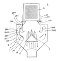
1は本発明のフレキシブルコンテナバッグ解袋装置(「以下、フレコンバッグ解袋装置と称する」)で、解袋装置ケーシング2と、中仕切りガイド板3と、粉体分配装置4と、第1種バッグ切断装置5から構成されている。
【0008】
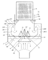
11は他の実施例のフレコンバッグ解袋装置で、解袋装置ケーシング2と、中仕切りガイド板3と、粉体分配装置4と、第2種バッグ切断装置6から構成されている。
【0009】
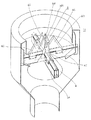
12は他の実施例のフレコンバッグ解袋装置で、解袋装置ケーシング2と、中仕切りガイド板3と、粉体分配装置4と、第3種バッグ切断装置7から構成されている。
【0010】
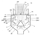
解袋装置ケーシング2は、ホッパー2Aと、このホッパーの上面に連設された中空フード2Bで構成され、中空フード2Bは縦筒状外壁2B1と、縦筒状外壁内の上辺に水平状態で連設された輪状の天板2B2と、天板2B2の内周に縦筒状外壁の高さ方向の略中央部に達するよう連設された縦筒状内壁2B3により当該縦筒状外壁内の上方部分に形成された空間部2B4から構成されている。
【0011】
中仕切りガイド板3は、縦筒部3Aと縦筒部の下辺に連設されたガイド部3Bから構成され、縦筒部3Aを空間部2B4内に位置せしめることで、当該空間部2B4内に上端が連通している粉塵同伴の上昇気流の外方縦流路2B42と内方縦流路2B41が構成されている。
【0012】
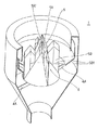
粉体分配装置4は、錐状に構成され、中空フード2Bの中央下部に位置して配設されている。4Aは当該粉体分配装置をホッパー2Aに連結支持する連杆である。
【0013】
第1種バッグ切断装置5は、粉体分配装置4の側面における上方部分に上方に向け起立された中央刃物5Aと、下方部分に上方に向け起立された外方刃物5Bから構成され、中央刃物5Aは、ペン先状ナイフ5A1を粉体分配装置の頂点を中心として平面十字に連続配置して構成され、外方刃物5Bは、ペン先状ナイフ5B1が中央刃物5Aにおけるペン先状ナイフ5A1の外方辺に連設され、中央刃物5Aは外方刃物5Bより高く構成されている。
【0014】
第2種バッグ切断装置6は、解袋装置ケーシング2の中空フード2B内に粉体分配装置4の上部に前後左右の梁体を平面十字に連結した梁6Aと、梁6Aの上面における中央に上方に向け起立された中央刃物6Bと、梁6Aの上面において中央刃物6Bに隣接して上方に向け起立された外方刃物6Cから構成され、中央刃物6Bは、ペン先状ナイフ6B1を粉体分配装置の頂点を中心として平面十字に連続配置して構成され、外方刃物6Cは、ペン先状ナイフ6C1が中央刃物6Bにおけるペン先状ナイフ6B1の外方辺に連設され、中央刃物6Bは外方刃物6Cより高く構成されている。
【0015】
第3種バッグ切断装置7は、バッグ切断装置部7Aとバッグ受け7Bから構成されている。
バッグ切断装置部7Aは、解袋装置ケーシング2における中空フード2Bの上面に連設された上方縦筒部7A1と、上方縦筒部内に平面十字に掛架された前後左右のレール7A2と、前後左右のレールに沿って中心から外方に向け移動自在に嵌着された移動枠7A3と、移動枠の上面内方端に上方に向け植設されたナイフ7A4から構成されている。
バッグ受け7Bは、上方縦筒部7A1の内面における所定箇所にナイフ7A4の高さより少しく低い高さをもって内方に向け突設された平面方形の小板で構成されている。
なお、移動枠7A3の移動自在の構成は、下記の通りである。
上方縦筒部7A1の外周面に移動枠7A3の延長方向に延出されたフレーム7A5と、このフレーム上に配設された油圧シリンダ7A6を移動枠の外方端に連結して構成されている。
【0016】
【実施例】
1.フレコンバッグ8から排出された粉体は、粉体分配装置4の傾斜面に沿って落下し、ホッパー2Aに堆積する。
ここで、粉体分配装置4の役割は、落下粉体をホッパー全周に均一分配し、ホッパー2Aの内壁側面で発生する粉塵上昇気流9を安定させて上部の中空フード2B内に導くことである。
2.中空フード2Bは、粉塵上昇気流のバルクを取込む部屋で、粉塵が系外(大気)に直接飛散するのを抑制するものである。
中空フード2B内が中仕切りガイド板3によって、粉塵同伴の上昇気流の外方縦流路2B42と内方縦流路2B41に構成されているのは、中空フード2Bに取込まれた粉塵上昇気流から効果的に粉塵を除去するためである。
すなわち、中仕切りガイド板3と中空フード2Bの外側壁の間に導かれた粉塵気流は、中空フードの側壁や中仕切りガイド板に衝突したり、方向転換させられ、粉塵は慣性によって気流から離脱して除塵される。
また、中空フード内の上部で反転した粉塵気流は、流速分布が均一化して減速され、粉塵の重力集塵も加わり防塵性能が向上する。
【0017】
3.第1種バッグ切断装置5は、中央刃物5Aと外方刃物5Bから構成され、中央刃物5Aは、ペン先状ナイフ5A1を粉体分配装置の頂点を中心として平面十字に連続配置して構成し、外方刃物5Bは、ペン先状ナイフ5B1が中央刃物5Aにおけるペン先状ナイフ5A1の外方辺に連設され、中央刃物5Aを外方刃物5Bより高く構成したのは下記のためである。
A.ペン先状ナイフなのでフレコンバッグの底面が容易に切断できる。
すなわち、フレコンバッグの自由落下による動荷重あるいは自重により当該フレコンバッグの底面を瞬時に切断できる。
B.中央刃物5Aが外方刃物5Bより高いので、切断時の面圧を最大にできる。
C.外方刃物などを連続配置することで開袋範囲を大きくして粉体排出を容易にできる。
D.以上の結果、装置の小型化を図って据え付け占有面積を小さくでき、メンテナンスを容易にして切断、排出の所要時間を短くできる。
【0018】
第2種バッグ切断装置6は、上述した第1種バッグ切断装置5の作用と同様の作用を営むが、梁6Aの上面に直接中央刃物6Bと外方刃物6Cを支持するよう構成されているから、強度を向上させることができる。
【0019】
4.第3種バッグ切断装置7におけるバッグ切断装置部7Aは、解袋装置ケーシング2における中空フード2Bに設けた中心から外方に向け移動自在に嵌着された移動枠7A3と、移動枠の上面内方端に上方に向け植設されたナイフ7A4から構成されているので、フレコンバッグの底面中心部付近にナイフを突き刺し、水平移動させて当該フレコンバッグを切断することにより、粉体はホッパーに排出される。
A.移動する複数のナイフにより粉体の排出速度を高めると共に、フレコンバッグ内の粉体残量を最小にすることができる。
B.また、ナイフはネジ止めなどによりカートリッジタイプにすることで、刃の摩耗やバッグ材質対応の交換を容易にできる。
C.以上の結果、比較的硬い塊状物や密度の小さい粉体でも切断が可能である。
【0020】
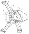
5.図1を参照して、バッグ受け台部10について説明する。
A.中空フード2Bの上面に連設された上方縦筒部10Aと、上方縦筒部内にバッグ受け台10Bが、例えば電磁マグネット方式にて通電中は水平力を維持してフレコンバッグの重量を支えるよう配設されている。
この場合、バッグ受け台10Bは、中空フードの周方向に3個程度設置される。
B.粉体が充填されたフレコンバッグは、クレーンなどにより吊下げられ、バッグ受け台10B上に静止される。
C.クレーンの吊りワイヤーが、フレコンバッグの落下距離以上の長さに緩められる。 D.ON,OFFスイッチによりバッグ受け台10Bの電磁力が開放(OFF)され、フレコンバッグは重力落下により第1種バッグ切断装置5上に落下する。
E.クレーンが巻上げられ、フレコンバッグが第1種バッグ切断装置5上の一定距離に達したら、クレーンの巻上げ操作を一時停止してフレコンバッグ内の粉体をホッパー内に排出する。
F.以上はフレコンバッグの材質などが切断しづらいものの場合の対策例である。
例えば、フレコンバッグの底面が一重布タイプなどの切断が容易なものについては、クレーンの降下速度あるいはフレコンバッグの自重量のみで切断可能となる。
また、このような場合にはコレコンバッグを所定の位置に固定して、切断刃を上下させて切断することも可能である。
【0021】
【発明の効果】
本発明は、上述の通り構成されているので次に記載する効果を奏する。
フレコンバッグの開袋作業において、粉塵公害を発生することなくクリーンな作業環境が確保できる。
加えて、集塵ブロワなどの動力を使わないので装置の小型化が可能となり、設備の価格もランニングコストも非常に安価となる。
また、構造の簡単化でメンテナンスが容易で人手がかからず省力化も可能となる。
【図面の簡単な説明】
【図1】本発明のものの概念図である。
【図2】同上の1部を切欠いた略図的斜視図である。
【図3】他の実施例のものの概念図である。
【図4】同上の1部を切欠いた略図的斜視図である。
【図5】他の実施例のものの概念図である。
【図6】同上の1部を切欠いた略図的斜視図である。
【符号の説明】
1 フレキシブルコンテナバッグ解袋装置
2 解袋装置ケーシング
3 中仕切りガイド板
4 粉体分配装置
5 第1種バッグ切断装置
11 フレキシブルコンテナバッグ解袋装置
6 第2種バッグ切断装置
12 フレキシブルコンテナバッグ解袋装置
7 第3種バッグ切断装置
8 フレキシブルコンテナバッグ
9 粉塵上昇気流[0001]
BACKGROUND OF THE INVENTION
INDUSTRIAL APPLICABILITY The present invention is a flexible material capable of suppressing dust generated when opening a flexible container bag (hereinafter referred to as a flexible container bag) that is handled in industries such as industry, agriculture, and food without power. The present invention relates to a container bag unpacking device.
[0002]
[Prior art]
Conventionally, this type is as follows.
1. In the case of opening a powder bag or the like, conventionally, an operator lifts a bag in a suspended state with a crane, and drops the powder directly onto the soil or a hopper.
2. As the above environmental measures and labor-saving measures, there is a “flexible container bag opening machine” (Japanese Patent Laid-Open No. 6-329135).
A. Dust is collected by making negative pressure in the casing by blower suction.
B. A protruding needle and an inclined knife are provided inside the casing, and the powder bag is dropped to open the bag.
[0003]
[Problems to be solved by the invention]
Those described in the prior art have the following problems.
1. Two people were required for the work environment to deteriorate due to the rising of dust and the cutting work by crane and cutter.
2. In the case of the “flexible container bag opening machine”, since all power is used, there are problems such as high equipment costs and running costs, and further maintenance costs.
The present invention has been made in view of such problems of the prior art, and an object of the present invention is to provide the following.
The present invention proposes a device that suppresses dust generated when opening powder from a flexible container bag or the like by a method that does not use power.
[0004]
[Means for Solving the Problems]
In order to achieve the above object, the present invention is as follows.
1. The dust generation mechanism when powder is applied to the hopper is
A. Primary scattering accompanied by crosswinds during the powder fall process,
B. This is roughly classified into secondary scattering that occurs when the falling powder collides with the inner wall of the hopper or the deposit surface in the hopper.
In general, primary scatter is not a problem if it is indoors, but secondary scatter occurs regardless of whether it is indoors or outdoors. Suppression is the point of dust generation prevention when powder falls.
The dust scattering outside the hopper as secondary scattering is caused by the dust accompanying the volume substitution of the falling powder in the hopper and the collision reversal flow to the deposit surface in the hopper.
The present invention guides the falling powder to the inner wall of the hopper by a distribution device and stably takes in the generated dust rising air flow into the hollow hood. Utilizes inertia and collision dust collection that are captured by collision.
In addition, the dust airflow inverted at the top of the hollow hood has a uniform flow velocity distribution, and gravity dust collection utilizing the natural sedimentation of particles is also added to increase dust removal efficiency.
2. Cutting (Example 1)
A flexible container bag filled with powder is suspended by an appropriate means such as a crane or hoist, and a plurality of nib-shaped knives with different tip heights in the hopper are continuously placed in a cross on the central and outer cutters. The bottom of the flexible container bag is cut in four directions by its own weight, and the powder is discharged.
3. Cutting (Example 2)
A flexible container bag filled with powder is allowed to stand in a bag receiver on a hollow hood.
At this time, a plurality of knives provided below the bag receiver pierce the bottom surface of the flexible container bag. Thereafter, the knife is moved horizontally to cut the bottom of the flexible container bag and discharge the powder.
[0005]
More specifically, it is as follows.
That is, the invention described in claim 1 is composed of the
[0006]
According to a second aspect of the present invention, in the first aspect, the
The invention according to
According to a fourth aspect of the present invention, in the third aspect of the invention, the
The invention according to claim 5 is the invention according to claim 1, comprising a third-type bag cutting device 7 instead of the first-type bag cutting device 5, and the third-type bag cutting device 7 is a bag opening device casing. 2, the upper surface of the
The invention according to claim 6 is the invention according to claim 5 , wherein the third type bag cutting device 7 is composed of a bag
[0007]
DETAILED DESCRIPTION OF THE INVENTION
DESCRIPTION OF THE PREFERRED EMBODIMENTS Embodiments of the present invention will be described based on examples with reference to the drawings.
1 is a flexible container bag unpacking apparatus (hereinafter referred to as a flexible container bag unpacking apparatus) of the present invention, which is a unpacking
[0008]
[0009]
[0010]
The unpacking
[0011]
The
[0012]
The powder distribution device 4 is configured in a conical shape and is disposed at the lower center of the
[0013]
The first-type bag cutting device 5 is composed of a
[0014]
The second type bag cutting device 6 includes a
[0015]
The third type bag cutting device 7 includes a bag
The bag
The bag receiver 7B is composed of a flat rectangular plate that protrudes inward at a predetermined position on the inner surface of the upper vertical cylindrical portion 7A1 with a height slightly lower than the height of the knife 7A4.
The movable configuration of the moving frame 7A3 is as follows.
A frame 7A5 extending in the extending direction of the moving frame 7A3 on the outer peripheral surface of the upper vertical cylindrical portion 7A1 and a hydraulic cylinder 7A6 disposed on the frame are connected to the outer end of the moving frame. .
[0016]
【Example】
1. The powder discharged from the
Here, the role of the powder distribution device 4 is to distribute the fallen powder uniformly over the entire circumference of the hopper, stabilize the
2. The
A
That is, the dust airflow guided between the
In addition, the dust airflow inverted at the upper part in the hollow hood is decelerated with a uniform flow velocity distribution, and the dust collection performance is improved by the addition of dust gravity dust collection.
[0017]
3. The first type bag cutting device 5 is composed of a
A. The bottom of the flexible container bag can be easily cut because it is a nib-shaped knife.
That is, the bottom surface of the flexible container bag can be instantaneously cut by a dynamic load or free weight due to the free fall of the flexible container bag.
B. Since the
C. By continuously arranging the outer cutters and the like, the bag opening range can be increased and the powder can be easily discharged.
D. As a result, the apparatus can be miniaturized, the installation area can be reduced, maintenance can be facilitated, and the time required for cutting and discharging can be shortened.
[0018]
The second type bag cutting device 6 operates in the same manner as the first type bag cutting device 5 described above, but is configured to directly support the
[0019]
4). The bag
A. A plurality of moving knives can increase the discharge speed of the powder and minimize the amount of powder remaining in the flexible container bag.
B. In addition, the knife can be made into a cartridge type by screwing or the like, so that the blade can be easily worn or exchanged for the bag material.
C. As a result, cutting is possible even with relatively hard lump or powder with low density.
[0020]
5. The
A. The upper
In this case, about three
B. The flexible container bag filled with the powder is suspended by a crane or the like and is rested on the
C. The crane's suspension wire is loosened to a length longer than the fall distance of the flexible container bag. D. The electromagnetic force of the
E. When the crane is wound up and the flexible container bag reaches a certain distance on the first type bag cutting device 5, the crane lifting operation is temporarily stopped and the powder in the flexible container bag is discharged into the hopper.
F. The above is an example of measures when the flexible container bag is difficult to cut.
For example, if the bottom surface of the flexible container bag is easy to cut, such as a single cloth type, it can be cut only by the descending speed of the crane or the weight of the flexible container bag.
In such a case, it is also possible to fix the core control bag at a predetermined position and cut the cutting blade up and down.
[0021]
【The invention's effect】
Since this invention is comprised as mentioned above, there exists an effect described below.
In opening the flexible container bag, a clean working environment can be secured without generating dust pollution.
In addition, since power such as a dust collection blower is not used, the apparatus can be miniaturized, and the equipment cost and running cost are very low.
In addition, the simplified structure facilitates maintenance, saves labor, and saves labor.
[Brief description of the drawings]
FIG. 1 is a conceptual diagram of the present invention.
FIG. 2 is a schematic perspective view in which a part of the above is cut away.
FIG. 3 is a conceptual diagram of another embodiment.
FIG. 4 is a schematic perspective view in which a part of the above is cut away.
FIG. 5 is a conceptual diagram of another embodiment.
FIG. 6 is a schematic perspective view in which a part of the above is cut away.
[Explanation of symbols]
DESCRIPTION OF SYMBOLS 1 Flexible container
Claims (6)
解袋装置ケーシング(2)は、ホッパー(2A)と、このホッパーの上面に連設された中空フード(2B)で構成され、
中空フード(2B)は縦筒状外壁(2B1)と、縦筒状外壁内の上辺に水平状態で連設された輪状の天板(2B2)と、天板(2B2)の内周に縦筒状外壁の高さ方向の略中央部に達するよう連設された縦筒状内壁(2B3)により当該縦筒状外壁内の上方部分に形成された空間部(2B4)から構成され、
中仕切りガイド板(3)は、縦筒部(3A)と縦筒部の下辺に連設されたガイド部(3B)から構成され、縦筒部(3A)を空間部(2B4)内に位置せしめることで、当該空間部(2B4)内に上端が連通している粉塵同伴の上昇気流の外方縦流路(2B42)と内方縦流路(2B41)が構成され、
粉体分配装置(4)は、錐状に構成され、中空フード(2B)の中央下部に位置して配設され、
第1種バッグ切断装置(5)は、粉体分配装置(4)の側面における上方部分に上方に向け起立された中央刃物(5A)と、下方部分に上方に向け起立された外方刃物(5B)から構成され、これら中央刃物(5A)と外方刃物(5B)は、ペン先状ナイフの先端高さを変え平面十字に連続配置したことを特徴とする
フレキシブルコンテナバッグ解袋装置。An unpacking device casing (2), a partition guide plate (3), a powder distribution device (4), and a first type bag cutting device (5),
The unpacking device casing (2) is composed of a hopper (2A) and a hollow hood (2B) connected to the upper surface of the hopper,
The hollow hood (2B) includes a vertical cylindrical outer wall (2B1), a ring-shaped top plate (2B2) continuously provided on the upper side of the vertical cylindrical outer wall, and a vertical cylinder on the inner periphery of the top plate (2B2). A vertical cylindrical inner wall (2B3) continuously provided so as to reach a substantially central portion in the height direction of the outer wall, and a space (2B4) formed in an upper portion of the vertical outer wall;
The partition guide plate (3) is composed of a vertical tube portion (3A) and a guide portion (3B) connected to the lower side of the vertical tube portion, and the vertical tube portion (3A) is positioned in the space portion (2B4). By letting down, the outer vertical flow path (2B42) and the inner vertical flow path (2B41) of the rising airflow accompanied by the dust, the upper end of which communicates with the space (2B4), are configured.
The powder distribution device (4) is configured in a conical shape and is disposed at the lower center of the hollow hood (2B),
The first type bag cutting device (5) includes a central cutter (5A) erected upward at an upper portion of a side surface of the powder distribution device (4) and an outer cutter (upward erected upward at a lower portion). The flexible container bag unpacking apparatus is characterized in that the center cutter (5A) and the outer cutter (5B) are continuously arranged in a plane cross by changing the tip height of the nib-shaped knife .
請求項1記載のフレキシブルコンテナバッグ解袋装置。 The central cutter (5A) of the first-type bag cutting device (5) is configured by continuously arranging a nib knife (5A1) in a plane cross with the vertex of the powder distribution device as the center, and an outer cutter (5B). ), The nib-shaped knife (5B1) is connected to the outer side of the nib-shaped knife (5A1) in the central blade (5A), and the central blade (5A) is configured to be higher than the outer blade (5B). The flexible container bag unpacking apparatus according to claim 1.
第2種バッグ切断装置(6)は、解袋装置ケーシング(2)の中空フード(2B)内に粉体分配装置(4)の上部に前後左右の梁体を平面十字に連結した梁(6A)と、梁(6A)の上面における中央に上方に向け起立された中央刃物(6B)と、梁(6A)の上面において中央刃物(6B)に隣接して上方に向け起立された外方刃物(6C)から構成され、これら中央刃物(6B)と外方刃物(6C)は、ペン先状ナイフの先端高さを変え平面十字に連続配置した
請求項1記載のフレキシブルコンテナバッグ解袋装置。In place of the first type bag cutting device (5), a second type bag cutting device (6) is provided,
The second type bag cutting device (6) has a beam (6A) in which the front and rear, left and right beam bodies are connected in a plane cross in the upper part of the powder distribution device (4) in the hollow hood (2B) of the unpacking device casing (2). ), A central cutter (6B) erected upward at the center on the upper surface of the beam (6A), and an outer cutter erected upward adjacent to the central cutter (6B) on the upper surface of the beam (6A) The flexible container bag unpacking apparatus according to claim 1, wherein the center cutter (6B) and the outer cutter (6C) are continuously arranged in a plane cross by changing the tip height of the pen-tip knife.
第3種バッグ切断装置(7)は、解袋装置ケーシング(2)における中空フード(2B)の上面にあって、フレキシブルコンテナバッグの底面中心付近から外周方向へ移動する複数のナイフからなる
請求項1記載のフレキシブルコンテナバッグ解袋装置。In place of the first type bag cutting device (5), a third type bag cutting device (7) is provided,
The third type bag cutting device (7) comprises a plurality of knives which are located on the upper surface of the hollow hood (2B) in the unpacking device casing (2) and which move in the outer peripheral direction from the vicinity of the center of the bottom surface of the flexible container bag. The flexible container bag unpacking apparatus according to 1.
請求項5記載のフレキシブルコンテナバッグ解袋装置。 The third type bag cutting device (7) is composed of a bag cutting device part and (7A) receiving bag (7B), the bag cutting device part (7A) is a hollow hood in the solution bag device casing (2) (2B ), The upper vertical cylinder (7A1) continuously provided on the upper surface, the front and rear left and right rails (7A2) hung on the plane cross in the upper vertical cylinder, and the front and rear left and right rails from the center outward. A movable frame (7A3) that is movably fitted in the direction of movement and a knife (7A4) that is implanted upward at the inner end of the upper surface of the movable frame, and the bag receiver (7B) 6. The flexible container bag unpacking apparatus according to claim 5, wherein the bag opening apparatus comprises a flat rectangular plate protruding inward at a predetermined position on the inner surface of 7A1) with a height slightly lower than the height of the knife (7A4).
Priority Applications (1)
| Application Number | Priority Date | Filing Date | Title |
|---|---|---|---|
| JP02659498A JP3607067B2 (en) | 1997-08-12 | 1998-01-23 | Flexible container bag opening machine |
Applications Claiming Priority (3)
| Application Number | Priority Date | Filing Date | Title |
|---|---|---|---|
| JP9-231805 | 1997-08-12 | ||
| JP23180597 | 1997-08-12 | ||
| JP02659498A JP3607067B2 (en) | 1997-08-12 | 1998-01-23 | Flexible container bag opening machine |
Related Child Applications (1)
| Application Number | Title | Priority Date | Filing Date |
|---|---|---|---|
| JP2004208020A Division JP2004323115A (en) | 1997-08-12 | 2004-07-15 | Flexible container bag unpacking device |
Publications (2)
| Publication Number | Publication Date |
|---|---|
| JPH11115920A JPH11115920A (en) | 1999-04-27 |
| JP3607067B2 true JP3607067B2 (en) | 2005-01-05 |
Family
ID=26364405
Family Applications (1)
| Application Number | Title | Priority Date | Filing Date |
|---|---|---|---|
| JP02659498A Expired - Fee Related JP3607067B2 (en) | 1997-08-12 | 1998-01-23 | Flexible container bag opening machine |
Country Status (1)
| Country | Link |
|---|---|
| JP (1) | JP3607067B2 (en) |
Families Citing this family (12)
| Publication number | Priority date | Publication date | Assignee | Title |
|---|---|---|---|---|
| KR101445128B1 (en) * | 2014-03-04 | 2014-11-04 | 원태연 | Food garbage basket with means for tearing vinyl bag |
| JP6310433B2 (en) * | 2015-10-09 | 2018-04-11 | 環テックス株式会社 | Device for breaking bag of flexible container bag containing objects |
| CN109421974A (en) * | 2017-09-04 | 2019-03-05 | 江苏邦琳纺织有限公司 | A kind of weaving powder dye bag breaking device |
| KR101989268B1 (en) * | 2018-01-22 | 2019-06-13 | 현대제철 주식회사 | Apparatus for feeding filler of electric furnace |
| CN111056176B (en) * | 2019-12-31 | 2022-06-03 | 广东沫益清环保科技有限公司 | Kitchen garbage separation garbage bin |
| CN114074779B (en) * | 2020-08-21 | 2025-10-24 | 百特国际有限公司 | Device for handling waste liquid bags |
| CN112660538A (en) * | 2021-01-19 | 2021-04-16 | 南京鑫启电子商务有限公司 | Supplementary cement dust fall equipment of building site |
| CN113023007A (en) * | 2021-03-04 | 2021-06-25 | 中国计量大学上虞高等研究院有限公司 | Automatic bag-unpacking and feeding device of pneumatic bag-beating type |
| CN113023013A (en) * | 2021-03-04 | 2021-06-25 | 中国计量大学上虞高等研究院有限公司 | Pneumatic bag beating type automatic unpacking and unloading device and pneumatic bag beating mechanism |
| CN114955141A (en) * | 2022-05-17 | 2022-08-30 | 中国恩菲工程技术有限公司 | Bag breaking device |
| CN118004791A (en) * | 2023-10-19 | 2024-05-10 | 福建龙亿粉体装备制造有限公司 | Dustless feeding system |
| CN118343380B (en) * | 2024-06-18 | 2024-08-06 | 四川张兵兵生物科技股份有限公司 | Quick-frozen raw beef tallow unsealing device and method |
-
1998
- 1998-01-23 JP JP02659498A patent/JP3607067B2/en not_active Expired - Fee Related
Also Published As
| Publication number | Publication date |
|---|---|
| JPH11115920A (en) | 1999-04-27 |
Similar Documents
| Publication | Publication Date | Title |
|---|---|---|
| JP3607067B2 (en) | Flexible container bag opening machine | |
| KR20210074570A (en) | Auto ripping apparatus of powder with reducing scattered dust | |
| CN211028058U (en) | Vibration shakeout machine with dust keeper | |
| US5802965A (en) | Bean sprout processing apparatus | |
| US4568029A (en) | Method and apparatus for unloading catalyst from a tubular reactor | |
| JP2004323115A (en) | Flexible container bag unpacking device | |
| CN202123065U (en) | Cyclone impurity removing machine | |
| CN213564623U (en) | Waste cleaning device for corrugated board production line | |
| JPH10128240A (en) | Wind power classifying device | |
| CN215355087U (en) | Vibrating inner cup static dust collector that disappears | |
| CN208323478U (en) | Vegetable deep-processing slicing device | |
| CN214871026U (en) | Cardboard is bloied and is removed bits equipment | |
| US4760968A (en) | Integrated dust containment system for rotary crusher/breakers and the like | |
| CN210497127U (en) | Large-capacity ultrafine powder dispersing and grading equipment | |
| JP3568788B2 (en) | Flexible container bag opening device | |
| CN216986767U (en) | Dust removal device for meal cutting process | |
| CN206631921U (en) | Vertical winnowing device for medicinal materials | |
| CN217436281U (en) | Broken packet of environment-friendly powder wrapping bag integrated device that gathers dust | |
| JP2002219447A (en) | Dust separation device | |
| RU2075700C1 (en) | Ventilation shelter | |
| KR102470842B1 (en) | Dust removal device | |
| CN208343549U (en) | Carton partition board cutting and dust-extraction unit | |
| CN222523040U (en) | A ton bag unpacking and feeding device | |
| CN112354665A (en) | Dust treatment device and environment-friendly solid waste treatment system comprising same | |
| CN212263514U (en) | Rice reducing mechanism in rice noodle manufacturing process |
Legal Events
| Date | Code | Title | Description |
|---|---|---|---|
| A131 | Notification of reasons for refusal |
Free format text: JAPANESE INTERMEDIATE CODE: A131 Effective date: 20040525 |
|
| A521 | Written amendment |
Free format text: JAPANESE INTERMEDIATE CODE: A523 Effective date: 20040715 |
|
| TRDD | Decision of grant or rejection written | ||
| A01 | Written decision to grant a patent or to grant a registration (utility model) |
Free format text: JAPANESE INTERMEDIATE CODE: A01 Effective date: 20040914 |
|
| A61 | First payment of annual fees (during grant procedure) |
Free format text: JAPANESE INTERMEDIATE CODE: A61 Effective date: 20041006 |
|
| R150 | Certificate of patent or registration of utility model |
Free format text: JAPANESE INTERMEDIATE CODE: R150 |
|
| LAPS | Cancellation because of no payment of annual fees |