【0001】
【発明の属する技術分野】
本発明は、リチウム含有複合窒化物の製造方法に関するものである。
【0002】
【従来の技術】
リチウム含有複合窒化物は、窒化リチウム(Li3N)を基本構造とし、その構造中のリチウムの一部を他元素で置換した化合物である。リチウム含有複合窒化物としては、一般式Li3−x−yMxN(式中MはTi、V、Cr、Mn、Fe、Co、Ni、およびCuからなる群より選ばれた少なくとも一種の遷移元素を表し、xおよびyは0<x≦0.8、0≦y≦2−xの範囲で示される実数を表す。)で表されるものである。これらの化合物は、結晶中に遷移元素を導入したことにより、窒化リチウムと同様に優れたリチウムイオン伝導性を有していると同時に電子伝導性も有するといった特徴を持ち、広い分野での応用が期待されている。ここで、xは遷移元素による置換割合を表す。また、yは非化学量論組成をとりうる範囲を表すが、化学量論組成であるy=0の組成が一般的である。
【0003】
このようなリチウム含有複合窒化物は、一般的には、金属リチウムを窒素と反応させることにより合成して得た窒化リチウムを出発原料に用い、これに遷移元素粉末または遷移元素の窒化物粉末を混合し、窒素雰囲気中または窒素ー水素混合雰囲気中で焼成することにより合成される(西島ら、Solid State Ionics 83(1996)107−111)。
【0004】
【発明が解決しようとする課題】
従来の合成方法では、不純物の混入が避けられず、またリチウムと遷移元素の組成比の正確な制御が困難であった。
【0005】
【課題を解決するための手段】
本発明は、リチウム、遷移元素M(MはTi、V、Cr、Mn、Fe、Co、Ni、およびCuからなる群より選ばれた少なくとも一種の遷移元素を示す)、およびリチウムと遷移元素Mとの合金からなる群より選ばれ、所定量のリチウムおよび遷移元素Mを含む原料を、窒素を含む雰囲気中で加熱処理することにより、一般式Li3−x−yMxN(式中、xおよびyは各々0<x≦0.8、0≦y≦2−xの範囲で示される実数を表す)で表されるリチウム含有複合窒化物を合成する。
ここで、合金とは、二種以上の金属からなる固溶体、共晶体、および金属間化合物の三種の状態の少なくとも一種を指すものとする。
【0006】
【発明の実施の形態】
本発明に用いるリチウム−遷移元素M合金のLi/Mのモル比は、目的とする窒化物と同じか、またはリチウム過剰(過剰量は15%以下)とすることが好ましい。
反応温度については、20℃以上、600℃以下の範囲内の温度であることが実用上好ましい。これは、反応温度が20℃未満では反応速度が遅く、600℃を超える温度ではリチウムの蒸発や昇華による組成の変化が大きくなる可能性があるためである。
反応時間については、反応速度およびリチウムの昇華等を考慮すると、6時間以上、50時間以下であることが好ましい。
【0007】
反応の雰囲気は、窒素雰囲気だけでなく、不活性ガスと窒素の混合雰囲気及び水素と窒素の混合雰囲気を用いることができる。ただし、いずれの場合も雰囲気中の水分量は露点−20℃以下、酸素分圧は1%以下であることが好ましい。水分量、酸素分圧のいずれか一方でも前記条件を満たさない場合には、不純物である酸化リチウム、水酸化リチウムの生成が著しく増加し、不純物抑制の効果が得られない。
【0008】
従来の合成法では、遷移元素Mの固溶が進み難いだけでなく、反応温度が700℃以上と比較的高いのでリチウムの昇華の影響を受けやすく、両者の影響で合成物の組成の正確な制御が困難であった。また、高い反応温度では副反応が起こりやすく、活物質中に微量の未反応物や副反応生成物等の不純物が混入しやすい。さらに、このような合成物に含まれる不純物の除去は極めて困難であった。
本発明の合成方法によると、微量の不純物成分の生成を抑制することができ、また、合成される材料組成を正確に制御することができ、かつ合成の再現性を大幅に向上させることができる。
【0009】
【実施例】
以下、本発明の実施例を詳細に説明するが、本発明はこれら実施例に限定されるものではない。
《実施例1》
本実施例では、遷移元素Mとしてコバルトを用いた例について説明する。
本実施例において、材料の混合、焼成、分析等の作業行程は、全て窒素雰囲気中で行った。また、雰囲気中の水分量は露点−60℃、酸素分圧は50ppmであった。
リチウム−コバルト複合窒化物は次のようにして合成した。
まず、所定組成比のリチウム−コバルト合金を銅製の容器に入れ、窒素雰囲気中、300℃で24時間保持し、窒素と反応させた。反応後、得られた黒灰色の化合物を粉砕しリチウム−コバルト複合窒化物粉末を得た。
リチウム−コバルト比については、Li/Coのモル比が2.9/0.1、2.8/0.2、2.6/0.4、2.4/0.6、2.2/0.8、2.1/0.9、2.0/1.0、1.9/1.1のそれぞれについて合成を行った。
いずれの場合にも、出発原料であるリチウム−コバルト合金のLi/Coモル比は目的とする窒化物と同じか、またはリチウム過剰(過剰量は15%以下)とすることが好ましい。本実施例においては、目的組成と同じとした。
【0010】
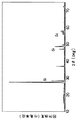
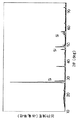
合成した各サンプルについて、それぞれCuのKα線を用いた粉末X線回折測定を行った。代表的なX線回折パターンとして図1にLi/Coのモル比が2.6/0.4のパターンを示した。他のいずれのサンプルでも窒化リチウム(Li3N)と同じ六方晶に基づく回折パターンが現れていた。しかし、Li/Coのモル比が1.9/1.1のものでは、金属Coに基づく回折ピークが見られ、Coが固溶しきれていないことを示していた。
なお、X線回折パターンに現れているシリコンの回折ピークは、内部標準として混合したものである。
【0011】
《比較例1》
比較のために、従来法による合成法として、窒化リチウム(Li3N)とコバルト粉末を出発原料として用い、リチウム−コバルト複合窒化物を合成した。
まず、所定組成比の窒化リチウムとコバルト粉末を銅製の容器に入れ、窒素雰囲気中、700℃で8時間保持し反応させた。反応後、得られた黒灰色の化合物を粉砕しリチウム−コバルト複合窒化物粉末を得た。
リチウム−コバルト比については、Li/Coのモル比が2.9/0.1、2.8/0.2、2.6/0.4、2.4/0.6、2.2/0.8、2.1/0.9、2.0/1.0、1.9/1.1のそれぞれについて合成を行った。
いずれの場合にも、出発原料の混合比は目的組成と同じとした。
【0012】
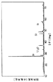
合成した各サンプルのそれぞれについて粉末X線回折測定を行った。代表的なX線回折パターンとして図2にLi/Coのモル比が2.6/0.4のパターンを示す。いずれも結晶系は窒化リチウム(Li3N)と同じ六方晶であったが、酸化リチウムと考えられる不純物のピークが現れており、単一相を得ることができなかった。特に、Li/Coのモル比が2.2/0.8以下のコバルト置換量の大きなサンプルでは、金属Coに基づく回折ピークが見られ、従来の合成法ではCo固溶量の限界値も小さいことがわかった。なお、X線回折パターンに現れているシリコンのピークは、内部標準として混合したものである。
【0013】
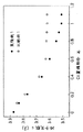
図3は実施例1および比較例1により得られた各サンプルの格子定数cをCo置換割合xに対してプロットして示す。実施例と比較し、比較例により合成した窒化物は、同じ仕込み組成でも格子定数が異なり、いずれの組成でもc軸が大きくなっている。これは、Co固溶量が少なくなっていることを表している。従来例の700℃で焼成する場合は、リチウムの昇華の影響は見られないものの、Coが固溶し難く、Co固溶量の制御も困難であると考えられる。特に、コバルト置換割合が0.8以上の場合には、格子定数変化が無く、これ以上の固溶が進んでいないと考えられる。
【0014】
《実施例2》
本実施例では、遷移元素MとしてTi、V、Cr、Mn、Fe、Ni、Cuの各元素を用いた。
まず、Li/Mのモル比が2.6/0.4であるリチウム−M合金粉末を銅製の容器に入れ、窒素雰囲気中、300℃で24時間保持し、窒素と反応させた。反応後、得られた黒灰色の化合物を粉砕しリチウム−Ti複合窒化物、リチウム−V複合窒化物、リチウム−Cr複合窒化物、リチウム−Mn複合窒化物、リチウム−Fe複合窒化物、リチウム−Ni複合窒化物、リチウム−Cu複合窒化物を得た。
いずれの場合にも、出発原料であるリチウム−M合金のLi/Mのモル比は、目的とする窒化物と同じとした。
【0015】
《比較例2》
置換元素をTi、V、Cr、Mn、Fe、Ni、Cuとした以外は比較例1と同様の方法でLi/Mのモル比が2.6/0.4の仕込み組成比のサンプルを合成した。
【0016】
実施例2および比較例2で合成した各サンプルについて粉末X線回折測定を行ったところ、いずれの置換元素を用いた場合でも、本発明の合成法によると、窒化リチウムと同様の六方晶系の結晶構造を有する化合物が不純物のない単一相で合成できていた。一方、従来例の比較例2によるサンプルは、いずれも酸化リチウムに基づく回折ピークが見られ、単一相は得られなかった。
以上のように、置換元素MがTi、V、Cr、Mn、Fe、Ni、Cuのいずれの場合も本発明の方法で合成することにより、従来法で合成した場合よりも不純物の少ないリチウム含有複合窒化物を得ることができた。
【0017】
《実施例3》
本実施例では、遷移元素Mをコバルトとし、リチウム、コバルト、リチウムーコバルト合金を出発原料として用いた場合について説明する。
なお、本実施例での材料混合、焼成、分析等の作業行程は全て窒素雰囲気中で行った。また、雰囲気中の水分量は露点−60℃、酸素分圧は50ppmであった。
リチウムーコバルト複合窒化物は次のようにして合成した。
まず、所定量のリチウムとコバルト粉末を銅製の容器に入れ、窒素雰囲気中、300℃で24時間保持し反応させた。反応後、得られた黒灰色の化合物を粉砕し、リチウムーコバルト複合窒化物粉末を得た。
【0018】
つぎに、リチウムとCo3Liを目的の組成比となるように混合し、銅製の容器に入れ、窒素雰囲気中、300℃で24時間保持し反応させた。反応後、得られた黒灰色の化合物を粉砕し、リチウムーコバルト複合窒化物粉末を得た。
いずれの場合も、リチウムーコバルト比についてはLi/Coモル比が2.6/0.4となるように合成を行った。また、出発原料であるリチウムーコバルト合金のLi/Coモル比は目的とする窒化物と同じか、またはリチウム過剰(過剰量は15%以下)とすることが好ましい。本実施例においては目的組成と同じとした。
また、反応温度については20℃以上、600℃以下の範囲の温度であることが実用上好ましい。これは、反応温度が20℃未満では反応速度が遅く、600℃を超える温度ではリチウムの昇華による組成の変化が大きくなる可能性があるためである。
【0019】
反応時間については本実施例では24時間としたが、反応速度およびリチウムの昇華等を考慮すると6時間以上、50時間以下であることが好ましい。
また、反応の雰囲気を窒素雰囲気としたが、不活性ガスと窒素の混合雰囲気、または水素と窒素の混合雰囲気中でもよい。ただし、いずれの場合も雰囲気中の水分量は露点−20℃以下、酸素分圧は1%以下であることが好ましい。水分量、酸素分圧のいずれか一方でも前記条件を満たさない場合には、不純物である酸化リチウム、水酸化リチウムの生成が著しく増加し、本発明の合成法による不純物抑制の効果が得られない。
【0020】
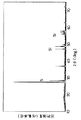
合成した各サンプルについてそれぞれ粉末X線回折測定を行った。図4にリチウムとコバルト粉末を用いて合成したサンプルの粉末X線回折パターンを、図5にリチウムとCo3Liを用いて合成したサンプルの粉末X線回折パターンをそれぞれ示す。いずれの場合も実施例1の図1と同様の回折パターンが得られ、六方晶に基づく回折パターンが現れていた。また、いずれのサンプルも図1と同様に酸化リチウムによると思われるピークは見られなかった。
さらに、X線回折パターンより各サンプルの格子定数cを求めたところ、いずれも、実施例1のLi/Co=2.6/0.4の比で合成した場合と同等の値であった。
従って、本実施例で合成したサンプルは、いずれも、実施例1の場合と同等のリチウムーコバルト複合窒化物が合成できていると考えられる。
本実施例では、出発原料としてリチウムとコバルトを用いた場合、およびリチウムとCo3Liを用いた場合について説明したが、Co3Li以外のリチウムーコバルト合金とリチウムの組み合わせ、および、リチウムーコバルト合金とコバルトの組み合わせでも同様にリチウムーコバルト複合窒化物を合成することができる。
【0021】
【発明の効果】
以上のように本発明によれば、不純物の生成を抑制し、組成が正確に制御されたリチウム含有複合窒化物を得ることができる。
【図面の簡単な説明】
【図1】本発明の一実施例により得たリチウム−コバルト複合窒化物のX線回折パターンを示す図である。
【図2】比較例のリチウム−コバルト複合窒化物のX線回折パターンを示す図である。
【図3】実施例および比較例のリチウム−コバルト複合窒化物の格子定数cとコバルト置換割合の関係を示す図である。
【図4】本発明の他の実施例により得たリチウム−コバルト複合窒化物のX線回折パターンを示す図である。
【図5】本発明の他の実施例により得たリチウム−コバルト複合窒化物のX線回折パターンを示す図である。[0001]
BACKGROUND OF THE INVENTION
The present invention relates to a method for producing a lithium-containing composite nitride.
[0002]
[Prior art]
Lithium-containing composite nitride is a compound having lithium nitride (Li 3 N) as a basic structure and a part of lithium in the structure substituted with another element. As the lithium-containing composite nitride, a general formula Li 3-xy M x N (wherein M is at least one selected from the group consisting of Ti, V, Cr, Mn, Fe, Co, Ni, and Cu) It represents a transition element, and x and y represent real numbers shown in the range of 0 <x ≦ 0.8 and 0 ≦ y ≦ 2-x.) These compounds have the characteristics that they have excellent lithium ion conductivity as well as lithium conductivity at the same time as lithium nitride by introducing a transition element into the crystal, and can be applied in a wide range of fields. Expected. Here, x represents a substitution ratio with a transition element. Further, y represents a range in which a non-stoichiometric composition can be taken, but a composition of y = 0 which is a stoichiometric composition is common.
[0003]
Such lithium-containing composite nitride generally uses lithium nitride obtained by synthesizing metal lithium with nitrogen as a starting material, and transition element powder or transition element nitride powder is used as the starting material. It is synthesized by mixing and firing in a nitrogen atmosphere or a nitrogen-hydrogen mixed atmosphere (Nishijima et al., Solid State Ionics 83 (1996) 107-111).
[0004]
[Problems to be solved by the invention]
In the conventional synthesis method, impurities are inevitably mixed, and it is difficult to accurately control the composition ratio between lithium and the transition element.
[0005]
[Means for Solving the Problems]
The present invention relates to lithium, transition element M (M represents at least one transition element selected from the group consisting of Ti, V, Cr, Mn, Fe, Co, Ni, and Cu), and lithium and transition element M. And a raw material containing a predetermined amount of lithium and the transition element M is heat-treated in an atmosphere containing nitrogen, whereby the general formula Li 3-xy M x N (where, x and y each represent a real number represented by a range of 0 <x ≦ 0.8 and 0 ≦ y ≦ 2-x).
Here, the alloy refers to at least one of three states of a solid solution composed of two or more metals, a eutectic, and an intermetallic compound.
[0006]
DETAILED DESCRIPTION OF THE INVENTION
The Li / M molar ratio of the lithium-transition element M alloy used in the present invention is preferably the same as the target nitride or excessive lithium (the excess amount is 15% or less).
About reaction temperature, it is practically preferable that it is the temperature within the range of 20 degreeC or more and 600 degrees C or less. This is because if the reaction temperature is less than 20 ° C., the reaction rate is slow, and if the reaction temperature exceeds 600 ° C., the composition may change greatly due to evaporation or sublimation of lithium.
The reaction time is preferably 6 hours or more and 50 hours or less in consideration of the reaction rate and lithium sublimation.
[0007]
As a reaction atmosphere, not only a nitrogen atmosphere but also a mixed atmosphere of inert gas and nitrogen and a mixed atmosphere of hydrogen and nitrogen can be used. However, in any case, the moisture content in the atmosphere is preferably a dew point of −20 ° C. or less and the oxygen partial pressure is preferably 1% or less. If either of the water content and the oxygen partial pressure does not satisfy the above conditions, the generation of impurities such as lithium oxide and lithium hydroxide is remarkably increased, and the effect of suppressing impurities cannot be obtained.
[0008]
In the conventional synthesis method, not only does the solid solution of the transition element M not easily proceed, but also the reaction temperature is relatively high at 700 ° C. or higher, so that it is easily affected by lithium sublimation. It was difficult to control. Further, side reactions are likely to occur at high reaction temperatures, and impurities such as trace amounts of unreacted substances and side reaction products are likely to be mixed in the active material. Furthermore, it has been extremely difficult to remove impurities contained in such a composite.
According to the synthesis method of the present invention, the generation of a trace amount of impurity components can be suppressed, the composition of the synthesized material can be accurately controlled, and the reproducibility of the synthesis can be greatly improved. .
[0009]
【Example】
Examples of the present invention will be described in detail below, but the present invention is not limited to these examples.
Example 1
In this embodiment, an example in which cobalt is used as the transition element M will be described.
In this example, the work processes such as mixing of materials, baking, and analysis were all performed in a nitrogen atmosphere. The moisture content in the atmosphere was a dew point of −60 ° C., and the oxygen partial pressure was 50 ppm.
The lithium-cobalt composite nitride was synthesized as follows.
First, a lithium-cobalt alloy having a predetermined composition ratio was placed in a copper container, held at 300 ° C. for 24 hours in a nitrogen atmosphere, and reacted with nitrogen. After the reaction, the obtained black gray compound was pulverized to obtain a lithium-cobalt composite nitride powder.
Regarding the lithium-cobalt ratio, the molar ratio of Li / Co is 2.9 / 0.1, 2.8 / 0.2, 2.6 / 0.4, 2.4 / 0.6, 2.2 / Synthesis was performed for 0.8, 2.1 / 0.9, 2.0 / 1.0, and 1.9 / 1.1.
In any case, the Li / Co molar ratio of the lithium-cobalt alloy that is the starting material is preferably the same as that of the target nitride or an excess of lithium (the excess amount is 15% or less). In this example, it was the same as the target composition.
[0010]
Each synthesized sample was subjected to powder X-ray diffraction measurement using Cu Kα rays. As a typical X-ray diffraction pattern, a pattern having a Li / Co molar ratio of 2.6 / 0.4 is shown in FIG. The diffraction pattern based on the same hexagonal crystal as lithium nitride (Li 3 N) appeared in any other samples. However, when the molar ratio of Li / Co was 1.9 / 1.1, a diffraction peak based on metal Co was observed, indicating that Co was not completely dissolved.
The silicon diffraction peaks appearing in the X-ray diffraction pattern are mixed as an internal standard.
[0011]
<< Comparative Example 1 >>
For comparison, lithium-cobalt composite nitride was synthesized using lithium nitride (Li 3 N) and cobalt powder as starting materials as a conventional synthesis method.
First, lithium nitride and cobalt powder having a predetermined composition ratio were put in a copper container, and reacted in a nitrogen atmosphere at 700 ° C. for 8 hours. After the reaction, the obtained black gray compound was pulverized to obtain a lithium-cobalt composite nitride powder.
Regarding the lithium-cobalt ratio, the molar ratio of Li / Co is 2.9 / 0.1, 2.8 / 0.2, 2.6 / 0.4, 2.4 / 0.6, 2.2 / Synthesis was performed for 0.8, 2.1 / 0.9, 2.0 / 1.0, and 1.9 / 1.1.
In any case, the mixing ratio of the starting materials was the same as the target composition.
[0012]
Powder X-ray diffraction measurement was performed for each of the synthesized samples. As a typical X-ray diffraction pattern, FIG. 2 shows a pattern having a Li / Co molar ratio of 2.6 / 0.4. In both cases, the crystal system was the same hexagonal crystal as lithium nitride (Li 3 N), but an impurity peak considered to be lithium oxide appeared, and a single phase could not be obtained. In particular, a sample having a large cobalt substitution amount with a Li / Co molar ratio of 2.2 / 0.8 or less shows a diffraction peak based on metal Co, and the conventional synthesis method has a small limit value for the amount of Co solid solution. I understood it. The silicon peak appearing in the X-ray diffraction pattern is a mixture of internal standards.
[0013]
FIG. 3 shows the lattice constant c of each sample obtained in Example 1 and Comparative Example 1 plotted against Co substitution ratio x. Compared with the examples, the nitrides synthesized according to the comparative examples have different lattice constants even with the same charge composition, and the c-axis is large with any composition. This represents that the amount of Co solid solution is reduced. In the case of firing at 700 ° C. in the conventional example, although the influence of sublimation of lithium is not observed, it is difficult to dissolve Co and to control the amount of Co solid solution. In particular, when the cobalt substitution ratio is 0.8 or more, there is no change in the lattice constant, and it is considered that no further solid solution has progressed.
[0014]
Example 2
In this example, Ti, V, Cr, Mn, Fe, Ni, and Cu were used as the transition element M.
First, a lithium-M alloy powder having a Li / M molar ratio of 2.6 / 0.4 was put in a copper container, held at 300 ° C. for 24 hours in a nitrogen atmosphere, and reacted with nitrogen. After the reaction, the obtained black gray compound was pulverized to obtain lithium-Ti composite nitride, lithium-V composite nitride, lithium-Cr composite nitride, lithium-Mn composite nitride, lithium-Fe composite nitride, lithium- Ni composite nitride and lithium-Cu composite nitride were obtained.
In either case, the Li / M molar ratio of the starting lithium-M alloy was the same as the target nitride.
[0015]
<< Comparative Example 2 >>
A sample having a composition ratio of Li / M of 2.6 / 0.4 was synthesized in the same manner as in Comparative Example 1 except that the substitution elements were Ti, V, Cr, Mn, Fe, Ni, and Cu. did.
[0016]
When the powder X-ray diffraction measurement was performed on each sample synthesized in Example 2 and Comparative Example 2, the hexagonal system similar to lithium nitride was obtained according to the synthesis method of the present invention, regardless of which substitution element was used. A compound having a crystal structure could be synthesized in a single phase without impurities. On the other hand, all the samples according to Comparative Example 2 of the conventional example showed a diffraction peak based on lithium oxide, and a single phase was not obtained.
As described above, when the substituting element M is Ti, V, Cr, Mn, Fe, Ni, or Cu, it is synthesized by the method of the present invention, so that it contains less lithium than when synthesized by the conventional method. A composite nitride could be obtained.
[0017]
Example 3
In this example, the case where the transition element M is cobalt and lithium, cobalt, or a lithium-cobalt alloy is used as a starting material will be described.
In addition, the work processes such as material mixing, firing, and analysis in this example were all performed in a nitrogen atmosphere. The moisture content in the atmosphere was a dew point of −60 ° C., and the oxygen partial pressure was 50 ppm.
Lithium-cobalt composite nitride was synthesized as follows.
First, a predetermined amount of lithium and cobalt powder was put in a copper container, and reacted in a nitrogen atmosphere at 300 ° C. for 24 hours. After the reaction, the resulting black gray compound was pulverized to obtain a lithium-cobalt composite nitride powder.
[0018]
Next, with lithium Co 3 Li were mixed so that the composition ratio of the object placed in a copper container in a nitrogen atmosphere, was held at 300 ° C. 24 hours. After the reaction, the resulting black gray compound was pulverized to obtain a lithium-cobalt composite nitride powder.
In either case, the lithium-cobalt ratio was synthesized so that the Li / Co molar ratio was 2.6 / 0.4. The Li / Co molar ratio of the lithium-cobalt alloy that is the starting material is preferably the same as the target nitride or excessive lithium (the excess amount is 15% or less). In this example, it was the same as the target composition.
The reaction temperature is preferably in the range of 20 ° C. or more and 600 ° C. or less. This is because if the reaction temperature is less than 20 ° C., the reaction rate is slow, and if the reaction temperature exceeds 600 ° C., the composition change due to lithium sublimation may increase.
[0019]
Although the reaction time was 24 hours in this example, it is preferably 6 hours or more and 50 hours or less in consideration of the reaction rate and lithium sublimation.
Further, although the reaction atmosphere is a nitrogen atmosphere, it may be a mixed atmosphere of inert gas and nitrogen or a mixed atmosphere of hydrogen and nitrogen. However, in any case, the moisture content in the atmosphere is preferably a dew point of −20 ° C. or less and the oxygen partial pressure is preferably 1% or less. When either of the moisture content and the oxygen partial pressure does not satisfy the above conditions, the generation of impurities such as lithium oxide and lithium hydroxide is remarkably increased, and the effect of suppressing impurities by the synthesis method of the present invention cannot be obtained. .
[0020]
Powder X-ray diffraction measurement was performed for each of the synthesized samples. FIG. 4 shows a powder X-ray diffraction pattern of a sample synthesized using lithium and cobalt powder, and FIG. 5 shows a powder X-ray diffraction pattern of a sample synthesized using lithium and Co 3 Li. In either case, a diffraction pattern similar to that in FIG. 1 of Example 1 was obtained, and a diffraction pattern based on hexagonal crystals appeared. Moreover, the peak considered to be based on lithium oxide was not seen in any sample like FIG.
Further, when the lattice constant c of each sample was determined from the X-ray diffraction pattern, all of them were the same values as those synthesized in the ratio of Li / Co = 2.6 / 0.4 in Example 1.
Therefore, it is considered that the samples synthesized in this example were able to synthesize lithium-cobalt composite nitride equivalent to that in Example 1.
In this embodiment, the case of using lithium-cobalt as a starting material, and has been described using lithium and Co 3 Li, Co 3 lithium-cobalt alloys and combinations of lithium other than Li, and lithium-cobalt Similarly, a lithium-cobalt composite nitride can be synthesized by a combination of an alloy and cobalt.
[0021]
【The invention's effect】
As described above, according to the present invention, it is possible to obtain a lithium-containing composite nitride in which the generation of impurities is suppressed and the composition is accurately controlled.
[Brief description of the drawings]
FIG. 1 is a diagram showing an X-ray diffraction pattern of a lithium-cobalt composite nitride obtained according to an example of the present invention.
FIG. 2 is a diagram showing an X-ray diffraction pattern of a lithium-cobalt composite nitride of a comparative example.
FIG. 3 is a graph showing the relationship between the lattice constant c and the cobalt substitution ratio of lithium-cobalt composite nitrides of examples and comparative examples.
FIG. 4 is a diagram showing an X-ray diffraction pattern of a lithium-cobalt composite nitride obtained by another example of the present invention.
FIG. 5 is a diagram showing an X-ray diffraction pattern of a lithium-cobalt composite nitride obtained by another example of the present invention.