JP3607037B2 - Line capacity test circuit for subscriber circuit - Google Patents
Line capacity test circuit for subscriber circuit Download PDFInfo
- Publication number
- JP3607037B2 JP3607037B2 JP09903297A JP9903297A JP3607037B2 JP 3607037 B2 JP3607037 B2 JP 3607037B2 JP 09903297 A JP09903297 A JP 09903297A JP 9903297 A JP9903297 A JP 9903297A JP 3607037 B2 JP3607037 B2 JP 3607037B2
- Authority
- JP
- Japan
- Prior art keywords
- circuit
- line
- subscriber
- integrator
- capacity test
- Prior art date
- Legal status (The legal status is an assumption and is not a legal conclusion. Google has not performed a legal analysis and makes no representation as to the accuracy of the status listed.)
- Expired - Fee Related
Links
Images

Landscapes
- Measurement Of Resistance Or Impedance (AREA)
- Monitoring And Testing Of Exchanges (AREA)
Description
【0001】
【発明の属する技術分野】
本発明は、加入者線の線路容量試験を行うための加入者回路の線路容量試験回路に関する。
【0002】
本発明に係る加入者回路の線路容量試験回路は、交換機からの制御信号により加入者回路の給電回路を制御して加入者線の容量試験を行い、容量測定データあるいは容量合否判定結果を加入者線監視信号として交換機に通知する場合などに用いられる。
【0003】
【従来の技術】
図3には加入者線の線路容量試験を行う従来の線路容量試験回路が示される。図示するように、加入者回路対応に設けられた加入者線試験装置引込みスイッチ(一次スイッチ)121 〜12n と、空間分割スイッチ(二次スイッチ)10と、試験装置11で試験回路を構成する。加入者線の容量試験を実施する場合、加入者回路対応に設けられた試験装置引込みスイッチ12およびそれらの出線をさらに集線するための空間分割形スイッチ10を通して、交換機に接続される複数の加入者線のうちから任意の一つの加入者線を試験装置11に引き込んで、試験装置11により当該加入者線の容量試験を行っていた。
【0004】
【発明が解決しようとする課題】
以上のように従来の線路容量試験回路は、線路容量試験を実現するために空間分割形スイッチ10および専用の試験装置11を必要としていた。この従来の線路容量試験回路は,通常の電話局のように非常に多くの加入者線を収容する場合については、システム全体に占める試験回路自身のハードウェアの割合は小さく、大きな問題とはならなかった。
【0005】
ところが、光リモート化が進み小規模の加入者を収容する小型交換システムを実現する場合、その各々の小型交換システムに対して上述の空間分割スイッチ10および専用試験装置11を設置したのでは、その小型交換システムに対する試験回路のハードウェアの割合が大きくなり、交換システムの小型化、軽量化、低コスト化が望めない。
【0006】
本発明はかかる問題点に鑑みてなされたものであり、その目的とするところは、線路容量試験回路の小型化、軽量化、低コスト化を図ることにある。
【0007】
【課題を解決するための手段】
上述の課題を解決するために、本発明に係る加入者回路の線路容量試験回路は、加入者線を給電回路に接続する一対のスイッチとは別に設けられた、前記加入者線を引き込むための一対の理想スイッチと、前記理想スイッチの一対の出線に接続される積分器とを具備し、容量試験時に、前記一対のスイッチで加入者線を充電した後に、該理想スイッチで該加入者線を前記給電回路側から前記積分器側に接続切替えし、該加入者線の線路充電電荷を該積分器に移動させ、該積分器の出力電圧に基づき加入者線の線路容量を判別するように構成され、前記積分器は、差動増幅器と、該差動増幅器の一方の入力端子と出力端子間に接続された第1のキャパシタとを備えて構成され、前記差動増幅器のもう一方の入力端子が、前記第1のキャパシタと同程度の容量値を有する第2のキャパシタを介して接地されるようにしたものである。
【0008】
このように構成することで、線路容量試験回路の小型化、軽量化、低コスト化を図ることが可能となるのに加え、加入者線に誘導される交流信号の同相信号に対し積分器の入力インタフェースを揃えて誘導による変動を第2のキャパシタで吸収することができ、測定容量値の精度を上げることが可能となる。
【0010】
【発明の実施の形態】
以下、図面を参照して本発明の実施形態を説明する。
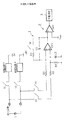
図1は本発明に係る加入者回路の線路容量試験回路の実施例を示す図である。ここでは、この線路容量試験回路はリモート局などの小型交換システムの加入者回路に適用されているものとし、各加入者回路毎にこの実施例回路が設けられている。
【0011】
図1において、スイッチS1、S2および給電回路A、給電回路Bは従来の加入者回路に相当する部分である。すなわち、スイッチS1、S2は加入者線を給電回路A、Bに引き込むためのスイッチであり、給電回路A、Bは加入者線に直流電流を供給するための回路である。
【0012】
本発明の線路容量試験回路は、理想スイッチS3、S4、積分器1、比較器2、容量判定回路3で構成される。理想スイッチS3、S4はそのオン時に線路に電流が流れ込まないもの(あるいは流れ込む電流が無視できる程度に小さいもの)であり、例えば光MOSスイッチ、リードリレー等が利用できる。この理想スイッチとしては例えば通常のトランジスタ・スイッチでベース電流が大きいタイプのものは適切でない。
【0013】
理想スイッチS3、S4は加入者線にスイッチS1、S2とは別に接続されており、加入者線はこの理想スイッチS3、S4により抵抗器R1、R2を通して積分器1に入力される。
【0014】
積分器1は、差動増幅器OP1の反転入力端子(−)と出力端子間にキャパシタC1を接続し、さらにこのキャパシタC1と並列に放電抵抗器R3と放電用スイッチS5の直列回路を接続し、差動増幅器OP1の非反転端子(+)を抵抗器R4とキャパシタC2の並列回路を通してアースして構成される。ここで、キャパシタC2の容量はキャパシタC1の容量と同じに設定される。
【0015】
比較器2は差動増幅器OP2からなり、この比較器2の非反転入力端子(+)に積分器1からの出力信号が入力され、その反転入力端子(−)には所定の基準電圧VREF が入力される。これにより比較器2は積分器1の出力信号のレベル検出を行う。容量判定回路3はこの比較器2からの比較結果信号に基づいて線路容量試験の合否を判定する。
【0016】
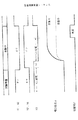
次にこの実施例回路の動作について図2を参照して説明する。図2はこの実施例の容量試験回路の制御シーケンスを示す図である。
【0017】
まず試験準備として、スイッチS1、S2および給電回路A、Bをオンし、加入者線の線間容量Cを充電し、測定可能な状態とする。この時はスイッチS3、S4は開放とするとともに、放電用スイッチS5を閉じてキャパシタC1の残留電荷を放電しておく。
【0018】
次にスイッチS1、S2を開放すると共に、スイッチS3、S4を閉じ、さらに時間td だけ遅延させてスイッチS5を開放することにより、容量測定が開始となる。この動作を行うことで、線間容量Cに充電された電荷が積分器1のキャパシタC1に移動し、積分器1の出力は線間容量Cの容量値と抵抗器R1の抵抗値で決まる時定数で変化し、やがて測定前の線間電圧値と線間容量Cの容量値およびキャパシタC1の容量値で決まる電圧値で落ちつく。例えば図2には積分器1の出力信号として、線間容量Cの容量値が大の場合と小の場合が示されている。
【0019】
この積分器1の出力電圧を比較器2に入力し、所定の電圧値VREF と比較して、得られる比較結果を試験開始後ある一定時間を経てから容量判定回路3で判定することで、線間容量試験を実現する。なお、この線路容量試験は、交換機からの加入者回路制御信号により実施し、容量合否判定結果は交換機に通知される。この通知は例えばループ・スキャンなどを行う場合と同様にして行われる。
【0020】
本実施例回路において、差動アンプOP1の入力端子(+)に接続されているキャパシタC2は、加入者線に誘導される交流信号の同相信号に対し積分器1の入力インタフェースを揃えて誘導による変動を吸収するためのものであり、キャパシタC1と同一の容量値とする。このキャパシタC2により、測定容量値の精度を上げることが可能となる。
【0021】
また、本実施例回路においては、スイッチS3、S4オンのタイミングからスイッチS5オンのタイミングまでに時間差td の遅延を設けている。これにより、加入者線の線間容量と並列に存在する絶縁抵抗の影響を小さくし、検出精度を上げることができる。
【0022】
以上、本発明の線路容量試験回路は小型交換システムに適したものとして説明したが、勿論、通常の交換機(大型交換システム)の加入者線にも適用可能であることは明白である。
【0023】
【発明の効果】
以上に説明したように、本発明によれば、加入者線間の容量試験が加入者回路で実現可能となるため、専用の試験装置接続スイッチおよび試験装置が不要となり、システムの小型化、軽量化、低コスト化が可能となる。
【0024】
【図面の簡単な説明】
【図1】本発明に係る加入者回路の線路容量試験回路の実施例を示す図である。
【図2】実施例回路の試験シーケンスを説明するための図である。
【図3】従来の線路容量試験回路を示す図である。
【符号の説明】
1 積分器
2 比較器
3 容量判定回路
A、B 給電回路
S1、S2 スイッチ
S3、S4 理想スイッチ
S5 放電用スイッチ
R1、R2、R3、R4 抵抗器
C 加入者線の線間容量
C1、C2 キャパシタ
OP1、OP2 差動アンプ[0001]
BACKGROUND OF THE INVENTION
The present invention relates to a line capacity test circuit of a subscriber circuit for performing a line capacity test of a subscriber line.
[0002]
The line capacity test circuit of the subscriber circuit according to the present invention controls the power supply circuit of the subscriber circuit by the control signal from the exchange to perform the capacity test of the subscriber line, and the capacity measurement data or the capacity pass / fail judgment result is sent to the subscriber. This is used when notifying the exchange as a line monitoring signal.
[0003]
[Prior art]
FIG. 3 shows a conventional line capacity test circuit for performing a line capacity test of a subscriber line. As shown in the figure, a test circuit is constituted by a subscriber line test apparatus lead-in switch (primary switch) 12 1 to 12 n , a space division switch (secondary switch) 10 and a
[0004]
[Problems to be solved by the invention]
As described above, the conventional line capacity test circuit requires the
[0005]
However, in the case of realizing a small switching system that accommodates small-scale subscribers as optical remote becomes more advanced, if the above-described
[0006]
The present invention has been made in view of such problems, and its object is to reduce the size, weight, and cost of the line capacitance test circuit.
[0007]
[Means for Solving the Problems]
In order to solve the above-mentioned problem, a line capacity test circuit for a subscriber circuit according to the present invention is provided separately from a pair of switches for connecting a subscriber line to a power feeding circuit, for drawing in the subscriber line. A pair of ideal switches and an integrator connected to a pair of outgoing lines of the ideal switch, and after charging a subscriber line with the pair of switches during a capacity test, the subscriber line with the ideal switch It was switched connection to said integrator side from the feeding circuit side, to move the line charges of the subscriber line to the integrator, so as to determine the line capacitance of the subscriber line based on the output voltage of the integrator And the integrator comprises a differential amplifier and a first capacitor connected between one input terminal and an output terminal of the differential amplifier, and the other input of the differential amplifier. A terminal connected to the first capacitor; It is obtained so as to be grounded via a second capacitor having a capacitance value of the degree.
[0008]
With the configuration as this, miniaturization of the line capacity test circuit, lighter, in addition to making it possible to reduce the cost, integrated with respect to the in-phase signal of the AC signal induced in the subscriber line Since the input interfaces of the detectors are aligned, the variation caused by the induction can be absorbed by the second capacitor, and the accuracy of the measured capacitance value can be increased.
[0010]
DETAILED DESCRIPTION OF THE INVENTION
Hereinafter, embodiments of the present invention will be described with reference to the drawings.
FIG. 1 is a diagram showing an embodiment of a line capacity test circuit for a subscriber circuit according to the present invention. Here, it is assumed that this line capacity test circuit is applied to a subscriber circuit of a small switching system such as a remote station, and this embodiment circuit is provided for each subscriber circuit.
[0011]
In FIG. 1, switches S1 and S2, a power feeding circuit A, and a power feeding circuit B are portions corresponding to a conventional subscriber circuit. That is, the switches S1 and S2 are switches for drawing the subscriber line into the power feeding circuits A and B, and the power feeding circuits A and B are circuits for supplying a direct current to the subscriber line.
[0012]
The line capacity test circuit of the present invention includes ideal switches S3 and S4, an
[0013]
The ideal switches S3 and S4 are connected to the subscriber line separately from the switches S1 and S2. The subscriber line is input to the
[0014]
The
[0015]
The
[0016]
Next, the operation of the circuit of this embodiment will be described with reference to FIG. FIG. 2 is a diagram showing a control sequence of the capacity test circuit of this embodiment.
[0017]
First, as preparation for the test, the switches S1 and S2 and the power feeding circuits A and B are turned on, and the line capacitance C of the subscriber line is charged to a measurable state. At this time, the switches S3 and S4 are opened, and the discharging switch S5 is closed to discharge the residual charge of the capacitor C1.
[0018]
Then while opening the switches S1, S2, closing the switch S3, S4, by further opening the switch S5 and delayed by time t d, the capacitance measurement is started. By performing this operation, the electric charge charged in the line capacitance C moves to the capacitor C1 of the
[0019]
The output voltage of the
[0020]
In the circuit of the present embodiment, the capacitor C2 connected to the input terminal (+) of the differential amplifier OP1 is guided by aligning the input interface of the
[0021]
Further, in the present embodiment the circuit is provided with a delay time difference t d in the timing of the switch S3, S4 ON until the timing of the switch S5 on. Thereby, the influence of the insulation resistance existing in parallel with the line capacitance of the subscriber line can be reduced, and the detection accuracy can be increased.
[0022]
Although the line capacity test circuit of the present invention has been described as being suitable for a small switching system, it is obvious that it can be applied to a subscriber line of a normal switching system (large switching system).
[0023]
【The invention's effect】
As described above, according to the present invention, since a capacity test between subscriber lines can be realized by a subscriber circuit, a dedicated test apparatus connection switch and a test apparatus are not required, and the system is reduced in size and weight. And cost reduction.
[0024]
[Brief description of the drawings]
FIG. 1 is a diagram showing an embodiment of a line capacity test circuit for a subscriber circuit according to the present invention.
FIG. 2 is a diagram for explaining a test sequence of the embodiment circuit;
FIG. 3 is a diagram showing a conventional line capacitance test circuit.
[Explanation of symbols]
DESCRIPTION OF
Claims (1)
容量試験時に、前記一対のスイッチで加入者線を充電した後に、該理想スイッチで該加入者線を前記給電回路側から前記積分器側に接続切替えし、該加入者線の線路充電電荷を該積分器に移動させ、該積分器の出力電圧に基づき加入者線の線路容量を判別するように構成され、
前記積分器は、差動増幅器と、該差動増幅器の一方の入力端子と出力端子間に接続された第1のキャパシタとを備えて構成され、前記差動増幅器のもう一方の入力端子が、前記第1のキャパシタと同程度の容量値を有する第2のキャパシタを介して接地された加入者回路の線路容量試験回路。Includes the pair of switches for connecting the subscriber line feed circuit is provided separately, and a pair of ideal switches for drawing the subscriber line, an integrator which is connected to a pair of output lines of the ideal switch And
During capacity test, after charging the subscriber line in the pair of switches, the subscriber line in the ideal switch switch connected to said integrator side from the feeding circuit side, said the line charges of the subscriber line Moved to an integrator, and configured to determine the line capacity of the subscriber line based on the output voltage of the integrator ;
The integrator includes a differential amplifier and a first capacitor connected between one input terminal and an output terminal of the differential amplifier, and the other input terminal of the differential amplifier is A line capacity test circuit for a subscriber circuit grounded via a second capacitor having a capacitance value comparable to that of the first capacitor .
Priority Applications (1)
| Application Number | Priority Date | Filing Date | Title |
|---|---|---|---|
| JP09903297A JP3607037B2 (en) | 1997-04-16 | 1997-04-16 | Line capacity test circuit for subscriber circuit |
Applications Claiming Priority (1)
| Application Number | Priority Date | Filing Date | Title |
|---|---|---|---|
| JP09903297A JP3607037B2 (en) | 1997-04-16 | 1997-04-16 | Line capacity test circuit for subscriber circuit |
Publications (2)
| Publication Number | Publication Date |
|---|---|
| JPH10290291A JPH10290291A (en) | 1998-10-27 |
| JP3607037B2 true JP3607037B2 (en) | 2005-01-05 |
Family
ID=14236025
Family Applications (1)
| Application Number | Title | Priority Date | Filing Date |
|---|---|---|---|
| JP09903297A Expired - Fee Related JP3607037B2 (en) | 1997-04-16 | 1997-04-16 | Line capacity test circuit for subscriber circuit |
Country Status (1)
| Country | Link |
|---|---|
| JP (1) | JP3607037B2 (en) |
Families Citing this family (2)
| Publication number | Priority date | Publication date | Assignee | Title |
|---|---|---|---|---|
| KR101340860B1 (en) * | 2005-06-03 | 2013-12-13 | 시냅틱스, 인코포레이티드 | Methods and systems for detecting a capacitance using sigma-delta measurement techniques |
| JP6695574B2 (en) * | 2016-07-29 | 2020-05-20 | ザインエレクトロニクス株式会社 | Transmission device and transmission / reception system |
-
1997
- 1997-04-16 JP JP09903297A patent/JP3607037B2/en not_active Expired - Fee Related
Also Published As
| Publication number | Publication date |
|---|---|
| JPH10290291A (en) | 1998-10-27 |
Similar Documents
| Publication | Publication Date | Title |
|---|---|---|
| JP5546990B2 (en) | Voltage balance control system for lithium ion battery and control method thereof | |
| JPS6078359A (en) | Static leonard device | |
| GB1475800A (en) | Telephone transmission system | |
| GB1567721A (en) | Telephone loop signalling detector | |
| GB2031696A (en) | Electronic speech detector | |
| JP2008522580A (en) | Voltage balance control system and method for lithium ion battery | |
| JP3607037B2 (en) | Line capacity test circuit for subscriber circuit | |
| US4447675A (en) | Ring-trip detector | |
| CN113541250B (en) | Battery charging control circuit and electronic equipment | |
| JPS59196666A (en) | Method and apparatus for controlling storage time of storage type photoelectric transducer | |
| JPH07248353A (en) | Power supply electric current measuring device | |
| JP4343489B2 (en) | Overcurrent detection delay circuit | |
| CN116839434B (en) | A system and method for detecting the capacitance voltage of an electronic detonator. | |
| US5450014A (en) | Test apparatus for detecting reverse insertion of a capacitor on a test board | |
| CN100414305C (en) | Light control electronic switch type automatic function selecting universal meter | |
| JP3251818B2 (en) | Method and apparatus for detecting presence / absence of disconnection of subscriber line | |
| JP3652784B2 (en) | Subscriber circuit with capacity test function | |
| JP2962184B2 (en) | Coin sorting standard data setting system | |
| KR970059817A (en) | Camera and Strobe Charging System | |
| EP1079591B1 (en) | Loop impedance measuring apparatus and method for subscriber loop interface circuits | |
| JP2001343402A (en) | DC current detector | |
| JPH10322917A (en) | Method and apparatus for determining deterioration of secondary battery | |
| CN219496530U (en) | Capacitance detection device | |
| JPH0358597A (en) | Call originating signal detecting circuit | |
| JPS5880957A (en) | Method of detecting loop current reference value in communication device |
Legal Events
| Date | Code | Title | Description |
|---|---|---|---|
| A977 | Report on retrieval |
Free format text: JAPANESE INTERMEDIATE CODE: A971007 Effective date: 20040521 |
|
| A131 | Notification of reasons for refusal |
Free format text: JAPANESE INTERMEDIATE CODE: A131 Effective date: 20040525 |
|
| A521 | Written amendment |
Free format text: JAPANESE INTERMEDIATE CODE: A523 Effective date: 20040720 |
|
| TRDD | Decision of grant or rejection written | ||
| A01 | Written decision to grant a patent or to grant a registration (utility model) |
Free format text: JAPANESE INTERMEDIATE CODE: A01 Effective date: 20041005 |
|
| A61 | First payment of annual fees (during grant procedure) |
Free format text: JAPANESE INTERMEDIATE CODE: A61 Effective date: 20041006 |
|
| R150 | Certificate of patent or registration of utility model |
Free format text: JAPANESE INTERMEDIATE CODE: R150 |
|
| LAPS | Cancellation because of no payment of annual fees |