JP3607021B2 - Connecting cable - Google Patents
Connecting cable Download PDFInfo
- Publication number
- JP3607021B2 JP3607021B2 JP31497596A JP31497596A JP3607021B2 JP 3607021 B2 JP3607021 B2 JP 3607021B2 JP 31497596 A JP31497596 A JP 31497596A JP 31497596 A JP31497596 A JP 31497596A JP 3607021 B2 JP3607021 B2 JP 3607021B2
- Authority
- JP
- Japan
- Prior art keywords
- anchor
- connecting cable
- connector
- steel
- unbonded
- Prior art date
- Legal status (The legal status is an assumption and is not a legal conclusion. Google has not performed a legal analysis and makes no representation as to the accuracy of the status listed.)
- Expired - Fee Related
Links
Images

Landscapes
- Bridges Or Land Bridges (AREA)
Description
【0001】
【発明の属する技術分野】
本発明は、連結ケーブルに関し、詳細には、例えば高架構造の高速道路における橋台上の橋桁間、あるいは架橋の橋台と橋桁間などを連結するのに用いられる連結ケーブルに関するものである。
【0002】
【従来の技術】
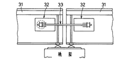
最近の阪神大震災において橋桁が落下したこともあって、それを防止するため、例えば図5及び図6に示す構成の落橋防止装置が提案されている。この落橋防止装置は、隣り合う橋桁31, 31のそれぞれの端部にブラケット32をボルト 32Aにより固設し、そのブラケット32, 32間に連結ケーブル33を配線して構成するものである。
【0003】
ブラケット32は、その詳細を図6に示すように、基板34上に、ほぼ中央に連結ケーブル33を挿通する孔35が設けられたフランジ板36と、このフランジ板36の前後面(連結ケーブル33の定着ナット側を後面とする)の左右に固定した補強板37, 38とを立設固定して基本的に構造されるとともに、フランジ板36の前面側の左右補強板37, 37の間には偏向具39を取付ける取付部40が形成され、その取付部40には地震力による全方向の曲げに対して有効に作用するために用いる偏向具39が取付けられている。またフランジ板36の後面には、ほぼ中央に連結ケーブル33を挿通する孔41, 42が設けられた緩衝材43と支圧板44とが、その挿通孔41, 42がフランジ板36の挿通孔35と同心上となるように積層して取付けられている。
【0004】
連結ケーブル33は、多重よりPC鋼より線(PC鋼より線を 7〜19本さらに撚り合わせた物)45に直接ポリエチレン被覆46を施したケーブル本体47と、このケーブル本体47の両端に圧着加工により取付けた鋼製スリーブ48とで基本的に構成されるとともに、鋼製スリーブ48の端部には定着ナット49を取付けるためのネジ部50がねじ切り加工され、また鋼製スリーブ48のケーブル本体47側には、ケーブル本体47にわたって合成ゴム(例えばエチレンプロピレンゴム等)の熱収縮チューブ51が被覆されている。
【0005】
上記連結ケーブル33は、鋼製スリーブ48側を、橋桁31の端部に取付けられたブラケット32の偏向具39、フランジ板36、支圧板44及び緩衝材43の挿通孔52, 35, 41, 42に通すとともに、支圧板44の背面に突き出ている鋼製スリーブ48にスプリング53及び止めプレート54を取付け、更に止めプレート54の背面に鋼製スリーブ48のネジ部50に螺合して定着ナット49を取付けることで落橋防止装置を構成する。
【0006】
上記落橋防止装置は、定着ナット49を締め付けることでスプリング53を圧縮しその反発力で連結ケーブル33の自重による撓みを無くすように配線し、スプリング53と緩衝材43によって地震の際の衝撃力を緩和するとともに、連結ケーブル33によって落橋を防止するものである。
【0007】
【発明が解決しようとする課題】
上述した落橋防止装置は、その構造からして十分な落橋防止機能を有するものと思われるが、次のような問題のあることが判明した。
【0008】
即ち、上記連結ケーブル33では、ケーブル本体47の容量(耐力)が大きくなればなるほど把持力を増す必要があるため鋼製スリーブ48を大径で且つ長くする必要があり、これにより偏向具39が大きくなるとともに、ブラケット32も長く且つ大きくなる。このため落橋防止装置に構成した場合に装置自体が長く大型となり、橋桁31への取付けの容易性が損なわれ、また取付け位置に制約を受けるなどの実用上の問題が生じる。
【0009】
また、連結ケーブル33の加工において、鋼製スリーブ48のケーブル本体47への取付けは、一般に鋼製スリーブ48にケーブル本体47を差し込み押出加工(圧着加工)を行った後にネジ切り加工を施して行われるので、鋼製スリーブ48へのメッキ等の防錆処理はネジ切り加工後に行わなければならないが、ケーブル本体47が取付けられた後ではメッキ等の防錆処理が難しく、そのため落橋防止装置に構成した際に鋼製スリーブ48の防錆対策としてフランジ板36の後面側を別個にカバーする保護キャップ55等を設ける必要がある。
【0010】
また、ケーブル本体33は、多重よりPC鋼より線45に直接ポリエチレン被覆46を施したものであるから、ポリエチレン被覆46が損傷すると耐食性が損なわれ易くなる問題があり、落橋防止装置の寿命にも影響を及ぼすことになる。
【0011】
本発明は、上記の問題点を解消するためになしたものであって、その目的は、ブラケットを極力大きくすることなく、延いては落橋防止装置をコンパクトに構成し得るとともに、耐食性及び各種特性に優れた連結ケーブルを提供するものである。
【0012】
【課題を解決するための手段】
上記の目的を達成するために、本発明に係る連結ケーブルは、両端部に鋼製スリーブが圧着加工されてなるアンボンドPC鋼より線の複数本をパラレルに配置するとともにその外周にポリエチレン本管が被覆されたケーブル本体の両端部に、アンボンドPC鋼より線を収容する長手方向の溝と外ネジとが施されたアンカーと、アンカーの外ネジに螺合する内ネジが施されたオーバーラップ管と、アンカーの外ネジに螺合する内ネジと外周に外ネジが施されたコネクターと、コネクターの外ネジに螺合する内ネジが施された定着ナットと、を備えてなるものである。
【0013】
そして、上記連結ケーブルにおいては、アンカー、コネクター、定着ナットに亜鉛メッキが施されてあってもよい。また、定着ナットの後方には、コネクターの外ネジに螺合させて複数本のアンボンドPC鋼より線の端部を収容するキャップが設けてあってもよい。
【0014】
上記本発明の連結ケーブルでは、次のような作用効果が得られる。即ち、
▲1▼:個々のアンボンドPC鋼より線の両端部に鋼製スリーブを圧着加工し、そのアンボンドPC鋼より線をアンカーの溝に収容し、そのアンカーをコネクターにねじ込む構成としているので、鋼製スリーブがアンカーとコネクターの端面に当接してアンボンドPC鋼より線の抜け止めがなされる。従って、アンカーとコネクターの大きさ(長さ及び径)はアンボンドPC鋼より線の線径にそれほど大きく影響されることがなく、特に長さは定着ナットが定着機能を発揮し得る長さであればよいことから、偏向具をフランジ前面近傍又は直接取付けることができ、またケーブル本体の容量(耐力)を大きくしてもブラケットの大きさ(特に長さ)を変える必要がなく、落橋防止装置がコンパクトに構成できる。
▲2▼:ケーブル本体は、グリースが塗布された上に高密度ポリエチレンを被覆したアンボンドPC鋼より線の複数本に、更にポリエチレン管を被覆した3重防食構造となっているため、耐食性に優れる。また、アンボンドPC鋼より線をパラレルに配置しているので、構成PC鋼より線の特性をそのまま生かせ、機械的性質等の物理的特性の向上が図れる。
▲3▼:アンカー、コネクターはケーブル本体の両端部にねじ込んで取付ける構造としているので、定着ナット等の金属部品と同様に予め亜鉛メッキ等の防錆処理を施すことができ、従来のような防錆の意味での保護キャップを必ずしも必要としない。
▲4▼:上記▲2▼、▲3▼に説明したように防食構造となっているため、使用中における点検周期を長くでき点検作業の改善、更には落橋防止装置の延命が期待できる。
【0015】
【発明の実施の形態】
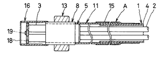
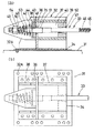
以下、本発明の実施形態を図面に基づいて説明する。図1は、本発明に係る連結ケーブルの説明図であって、aは全体斜視図、bはaの一端側を展開して示す部品の斜視図、図2は、本発明に係る連結ケーブルの一端側の断面図である。
【0016】
ケーブル本体1は、グリースが塗布された上に高密度ポリエチレンを被覆したアンボンドPC鋼より線2の両端に鋼製スリーブ3を圧着加工して取付け、本例では、その4本をパラレルに配置してポリエチレン本管4で被覆して構成されている。
【0017】
アンカー5は、外周面にねじ切り加工して外ネジ6が加工され、更にほぼ等間隔にアンボンドPC鋼より線2を収容する溝7が長手(軸)方向に平行に穿設されており、加工後に亜鉛メッキによる防錆処理が施されている。
【0018】
コネクター8は、外周面にねじ切り加工して外ネジ9が加工され、更に内周面にアンカー5の外ネジ6に螺合する内ネジ10がねじ切り加工されており、加工後に亜鉛メッキによる防錆処理が施されている。
【0019】
オーバーラップ管11は、ポリエチレン製であってその内径はケーブル本体1のポリエチレン本管4の外径より大きく、内周面の一端側にはアンカー5の外ネジ6に螺合する内ネジ12がねじ切り加工されている。
【0020】
定着ナット13は、コネクター8の外ネジ9に螺合する内ネジ14がねじ切り加工されており、加工後に亜鉛メッキによる防錆処理が施されている。
【0021】
熱収縮チューブ15は、合成ゴム(例えばエチレンプロピレンゴム等)でオーバーラップ管11の外径より大径に形成され、連結ケーブルを組立てた後に熱収縮させてポリエチレン本管4とオーバーラップ管11の重なり部を気密に保持する。
【0022】
キャップ16は、開放端の内周面にコネクター8の外ネジ9に螺合する内ネジ17がねじ切り加工されており、加工後に亜鉛メッキによる防錆処理が施されている。
【0023】
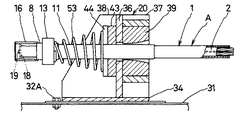
本発明の連結ケーブルAは、上述した部品を組立てて構成されるものであって次のように組立てられる。即ち、予めケーブル本体1にコネクター8、オーバーラップ管11及び熱収縮チューブ15を装入するとともに、ケーブル本体1の端部のポリエチレン本管4を所定長さ取り除く。その取り除いた部分に露出した4本のアンボンドPC鋼より線2を、アンカー5の収容溝7に収容するとともに、コネクター8を引き戻してアンカー5の外周に螺合させる。このとき、アンボンドPC鋼より線2の鋼製スリーブ3がアンカー5とコネクター8の端面に当接するように調節する。この後、オーバーラップ管11を引き戻してアンカー5の外周にコネクター8の端面に当接するまで螺合させた後、他端側のポリエチレン本管4との重なり部を熱収縮チューブ15で気密に被覆する。また、コネクター8の外周に定着ナット13とキャップ16を螺合させて取付ける。このとき、鋼製スリーブ3の端面から突出しているアンボンドPC鋼より線2の端を押え板18の孔に通し、その押え板18をボルト19によりアンカー5の端面の中央にねじ込み固定するようにしてもよい。これにより、鋼製スリーブ3を含むアンボンドPC鋼より線2の端が一体的に拘束される。
【0024】
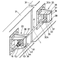
上記の如く組立て得る連結ケーブルAは、架設現場において落橋防止装置として図3及び図4に示すように、従来と同様に、隣り合う橋桁31, 31のそれぞれの端部にブラケット20をボルト 32A により固設し、そのブラケット20, 20間に連結ケーブルAを配線して使用される。
【0025】
上記落橋防止装置に使用されるブラケット20は、従来の落橋防止装置に使用されるブラケット32と基本的には同構造のもので、基板34上に、ほぼ中央に連結ケーブルAを挿通する孔35が設けられたフランジ板36と、このフランジ板36の前後面(連結ケーブル33の定着ナット側を後面とする)の左右に固定した補強板37, 38とを立設固定して構造されるとともに、フランジ板36の前面側の左右補強板37, 37の間には偏向具39を取付ける取付部40が形成され、その取付部40には地震力による全方向の曲げに対して有効に作用するために用いる偏向具39が取付けられ、またフランジ板36の後面には、ほぼ中央に連結ケーブルAを挿通する孔41, 42が設けられた緩衝材43と支圧板44とが、その挿通孔41, 42がフランジ板36の挿通孔35と同心上となるように積層して取付けられている。そして、本発明の連結ケーブルAでは、アンボンドPC鋼より線2の保持をアンカー5とコネクター8の端面に鋼製スリーブ3を当接させて行う形式で、アンカー5とコネクター8の長さが短く構成されているので、偏向具39をブラケット20のフランジ板36の前面に取付けることができる。これによりブラケット20の長さが短くできることから、落橋防止装置全体がコンパクトに構成できる。因みに、荷重 100tf( 980kN)の本発明の連結ケーブルAと従来技術の項で説明した多重よりPC鋼より線を用いた連結ケーブル33とで、偏向具39から連結ケーブルの端までの長さを測定したところ、従来の連結ケーブル33では 485mmであるのに対して本発明の連結ケーブルAではその半分の 220mmと短くできることが確認された。
【0026】
なお、ブラケット20に従来の連結ケーブル33を取付け使用することは可能であるが、この場合、ケーブル本体47の両端に圧着加工により取付けた鋼製スリーブ48が長く偏向具39にかかり、鋼製スリーブ48のケーブル本体47側が偏向基点となり偏向具39の機能が発揮されないばかりか、鋼製スリーブ48の端でケーブル本体47を損傷することになるので、これを防止するため、鋼製スリーブ48のケーブル本体47側の端が偏向具39にかからないようにフランジ板36又は支圧板44を厚く形成するなどの工夫を要することになり、何れにせよ落橋防止装置全体の長さは長くなる。
【0027】
また、本発明の連結ケーブルAと従来の連結ケーブル33との構造の相違から明らかなように、本発明の連結ケーブルAでは、上記利点の外に、ケーブル本体1が、グリースを塗布した上に高密度ポリエチレンを被覆したアンボンドPC鋼より線2の4本に、更にポリエチレン管4を被覆した3重防食構造となっているため、耐食性に優れる。また、アンボンドPC鋼より線2の4本をパラレルに配置しているので、構成PC鋼より線の特性がそのまま生かせ、機械的性質等の物理的特性の向上が期待される。また、アンカー5、コネクター8、定着ナット13、キャップ16は亜鉛メッキ等の防食処理が施されており、必ずしも従来のような防錆の意味での保護キャップを必要としない。
【0028】
なお、上記例では、アンボンドPC鋼より線2を4本用いた場合を例に説明したが、本発明はこの例に限定されるものではなく、取付ける部分の設計荷重に合わせ適宜2以上十数本、好ましくは 4〜12本の使用が可能である。
【0029】
【発明の効果】
上述したように、本発明に係る連結ケーブルによれば、偏向具を落橋防止装置を構成するブラケットのフランジ前面の近傍又は直接取付けることができるので、ブラケットの長さを短く構成でき、落橋防止装置全体がコンパクトに構成できる。また、ケーブル本体が、グリースを塗布した上に高密度ポリエチレンを被覆したアンボンドPC鋼より線の複数本に、更にポリエチレン管を被覆した3重防食構造となっているため、耐食性に優れる。また、アンボンドPC鋼より線をパラレルに配置しているので、構成PC鋼より線の特性をそのまま生かせ、機械的性質等の物理的特性の向上が図れる。また更に、アンカー、コネクターは、ケーブル本体の両端部にねじ込んで取付ける構造としているので、定着ナット等の金属部品と同様に予め亜鉛メッキ等の防錆処理を施すことができ、必ずしも従来のような防錆の意味での保護キャップを必要としない。
【0030】
更に、本発明に係る連結ケーブルによれば、十分な防食構造となっているので、使用中における点検周期を長くでき点検作業の改善、更には落橋防止装置の延命が期待できる。
【図面の簡単な説明】
【図1】本発明に係る連結ケーブルの説明図であって、aは全体斜視図、bはaの一端側を展開して示す部品の斜視図である。
【図2】本発明に係る連結ケーブルの一端側の断面図である。
【図3】本発明に係る連結ケーブルを落橋防止装置に組立てた全体斜視図である。
【図4】図3の一部断面説明図である。
【図5】落橋防止装置の全体概念図である。
【図6】従来の連結ケーブルを落橋防止装置に組立てた説明図であって、aは断面図、bはaの上面図である。
【符号の説明】
1:ケーブル本体 2:アンボンドPC鋼より線
3:鋼製スリーブ 4:ポリエチレン本管 5:アンカー
6,9:外ネジ 7:収容溝 8:コネクター
10, 12, 14:内ネジ 11:オーバーラップ管 13:定着ナット
15:熱収縮チューブ 16:キャップ 17:内ネジ
18:押え板 19:ボルト 20:ブラケット
A:連結ケーブル[0001]
BACKGROUND OF THE INVENTION
The present invention relates to a connecting cable, and more particularly to a connecting cable used for connecting, for example, a bridge girder on an abutment in an elevated highway or a bridge abutment and a bridge girder.
[0002]
[Prior art]
In order to prevent the bridge girder from dropping due to the recent Great Hanshin Earthquake, for example, a falling bridge prevention device having the configuration shown in FIGS. 5 and 6 has been proposed. This falling bridge prevention device is configured by fixing a
[0003]
As shown in detail in FIG. 6, the
[0004]
The connecting
[0005]
The connecting
[0006]
The falling bridge prevention device compresses the
[0007]
[Problems to be solved by the invention]
The above-described bridge failure prevention device is considered to have a sufficient fall prevention function due to its structure, but has been found to have the following problems.
[0008]
That is, in the connecting
[0009]
In processing the connecting
[0010]
Further, since the
[0011]
The present invention has been made to solve the above-mentioned problems, and its purpose is to make the falling bridge prevention device compact without increasing the size of the bracket as much as possible, as well as corrosion resistance and various characteristics. It provides an excellent connection cable.
[0012]
[Means for Solving the Problems]
In order to achieve the above-mentioned object, the connecting cable according to the present invention includes a plurality of unbonded PC steel strands in which steel sleeves are crimped at both ends, and a polyethylene main pipe is disposed on the outer periphery thereof in parallel. An anchor pipe with a longitudinal groove and an external thread that receive unbonded PC steel strands at both ends of the coated cable body, and an overlap pipe that has an internal thread that engages with the external thread of the anchor And an inner screw that is screwed to the outer screw of the anchor, a connector that is provided with an outer screw on the outer periphery, and a fixing nut that is provided with an inner screw that is screwed to the outer screw of the connector.
[0013]
In the connection cable, the anchor, the connector, and the fixing nut may be galvanized. In addition, a cap that accommodates the ends of a plurality of unbonded PC steel wires may be provided behind the fixing nut so as to be screwed into an external screw of the connector.
[0014]
In the connection cable of the present invention, the following operational effects are obtained. That is,
(1): Steel sleeve is crimped to both ends of each unbonded PC steel wire, the unbonded PC steel wire is accommodated in the anchor groove, and the anchor is screwed into the connector. The sleeve comes into contact with the end surfaces of the anchor and the connector to prevent the unbonded PC steel from coming off. Therefore, the size (length and diameter) of the anchor and connector is not significantly affected by the wire diameter of the unbonded PC steel. Especially, the length should be such that the fixing nut can exert the fixing function. Therefore, it is possible to attach the deflecting tool near the flange front or directly, and even if the capacity (proof strength) of the cable body is increased, there is no need to change the size (especially length) of the bracket. Can be configured compactly.
(2): The cable body has a triple anticorrosion structure in which multiple unbonded PC steel wires coated with high-density polyethylene coated with grease and coated with polyethylene pipe are coated with a polyethylene tube, so it has excellent corrosion resistance. . In addition, since the unbonded PC steel wires are arranged in parallel, the properties of the wires can be utilized as they are from the constituent PC steel, and the physical properties such as mechanical properties can be improved.
(3): Since the anchor and connector are screwed to both ends of the cable body, they can be pre-treated with rust-proofing such as galvanizing in the same way as metal parts such as fixing nuts. A protective cap in the sense of rust is not always necessary.
{Circle around (4)} As described in {circle over (2)} and {circle around (3)} above, since the anticorrosion structure is used, the inspection cycle during use can be lengthened, and the inspection work can be improved, and the life span of the falling bridge prevention device can be expected.
[0015]
DETAILED DESCRIPTION OF THE INVENTION
Hereinafter, embodiments of the present invention will be described with reference to the drawings. FIG. 1 is an explanatory diagram of a connecting cable according to the present invention, in which a is an overall perspective view, b is a perspective view of a part shown by developing one end side of a, and FIG. 2 is a perspective view of the connecting cable according to the present invention. It is sectional drawing of the one end side.
[0016]
The
[0017]
The
[0018]
The
[0019]
The
[0020]
The fixing
[0021]
The heat shrinkable
[0022]
The
[0023]
The connecting cable A of the present invention is constructed by assembling the above-described components, and is assembled as follows. That is, the
[0024]
As shown in FIG. 3 and FIG. 4, the connecting cable A that can be assembled as described above is used as a fall prevention device at the construction site, as in the prior art, with
[0025]
The
[0026]
Although it is possible to attach and use the conventional connecting
[0027]
Further, as is apparent from the difference in structure between the connecting cable A of the present invention and the conventional connecting
[0028]
In the above example, the case where four unbonded
[0029]
【The invention's effect】
As described above, according to the connecting cable according to the present invention, the deflecting tool can be attached in the vicinity of or directly on the front surface of the flange of the bracket constituting the falling bridge prevention device, so that the length of the bracket can be reduced, and the falling bridge prevention device. The whole can be configured compactly. Moreover, since the cable main body has a triple anticorrosion structure in which a plurality of unbonded PC steel wires coated with grease and coated with high-density polyethylene are further coated with a polyethylene tube, the cable body is excellent in corrosion resistance. In addition, since the unbonded PC steel wires are arranged in parallel, the properties of the wires can be utilized as they are from the constituent PC steel, and the physical properties such as mechanical properties can be improved. Furthermore, since the anchor and the connector are structured to be screwed and attached to both ends of the cable body, it can be subjected to a rust prevention treatment such as galvanization in advance in the same manner as a metal part such as a fixing nut. No protective cap is required for rust prevention.
[0030]
Furthermore, since the connection cable according to the present invention has a sufficient anticorrosion structure, the inspection cycle during use can be lengthened, and the inspection work can be improved, and further, the life span of the falling bridge prevention device can be expected.
[Brief description of the drawings]
FIG. 1 is an explanatory view of a connecting cable according to the present invention, in which a is an overall perspective view, and b is a perspective view of a part in which one end side of a is developed.
FIG. 2 is a cross-sectional view of one end side of a connection cable according to the present invention.
FIG. 3 is an overall perspective view of a connecting cable according to the present invention assembled into a fallen bridge prevention device.
4 is a partial cross-sectional explanatory view of FIG. 3;
FIG. 5 is an overall conceptual diagram of a fallen bridge prevention device.
FIGS. 6A and 6B are explanatory views in which a conventional connecting cable is assembled into a falling bridge prevention device, where a is a cross-sectional view and b is a top view of a.
[Explanation of symbols]
1: Cable body 2: Unbonded PC steel strand 3: Steel sleeve 4: Polyethylene main pipe 5: Anchor 6, 9: Outer screw 7: Housing groove 8:
Claims (3)
Priority Applications (1)
| Application Number | Priority Date | Filing Date | Title |
|---|---|---|---|
| JP31497596A JP3607021B2 (en) | 1996-11-26 | 1996-11-26 | Connecting cable |
Applications Claiming Priority (1)
| Application Number | Priority Date | Filing Date | Title |
|---|---|---|---|
| JP31497596A JP3607021B2 (en) | 1996-11-26 | 1996-11-26 | Connecting cable |
Publications (2)
| Publication Number | Publication Date |
|---|---|
| JPH10152810A JPH10152810A (en) | 1998-06-09 |
| JP3607021B2 true JP3607021B2 (en) | 2005-01-05 |
Family
ID=18059926
Family Applications (1)
| Application Number | Title | Priority Date | Filing Date |
|---|---|---|---|
| JP31497596A Expired - Fee Related JP3607021B2 (en) | 1996-11-26 | 1996-11-26 | Connecting cable |
Country Status (1)
| Country | Link |
|---|---|
| JP (1) | JP3607021B2 (en) |
Families Citing this family (4)
| Publication number | Priority date | Publication date | Assignee | Title |
|---|---|---|---|---|
| JP4200660B2 (en) * | 2001-01-18 | 2008-12-24 | 敏雄 藤岡 | Seismic isolation structure dropout prevention device |
| JP2008303573A (en) * | 2007-06-06 | 2008-12-18 | Shinko Wire Co Ltd | Seismic reinforcement cable |
| CN113944102A (en) * | 2020-07-18 | 2022-01-18 | 武汉日意科技有限公司 | Anti-icing bridge cable |
| JP2023117085A (en) * | 2022-02-10 | 2023-08-23 | 首都高速道路株式会社 | cable protector |
Family Cites Families (2)
| Publication number | Priority date | Publication date | Assignee | Title |
|---|---|---|---|---|
| JPH047213Y2 (en) * | 1988-12-05 | 1992-02-26 | ||
| JPH05230809A (en) * | 1992-02-18 | 1993-09-07 | Kumagai Gumi Co Ltd | Stay cable fixing method and fixing device and vibration isolator for cable stayed bridge |
-
1996
- 1996-11-26 JP JP31497596A patent/JP3607021B2/en not_active Expired - Fee Related
Also Published As
| Publication number | Publication date |
|---|---|
| JPH10152810A (en) | 1998-06-09 |
Similar Documents
| Publication | Publication Date | Title |
|---|---|---|
| JP3730513B2 (en) | Apparatus and method for securing construction elements and structural cables | |
| JP3607021B2 (en) | Connecting cable | |
| US6173104B1 (en) | Dead end connector for fiber optic cable | |
| JPH11323823A (en) | Suspending device for construction structure | |
| IT8422200A1 (en) | METHOD AND STRUCTURE FOR SUPPORTING A STEEL-REINFORCED ALUMINUM CONDUCTOR OF THE INTERSTICE TYPE | |
| DE19801786A1 (en) | Anchor system for tensioners and anchors in prestressed concrete construction | |
| US6196091B1 (en) | Drill bit for applying torque to a fastener | |
| CA1078485A (en) | Contraction terminating device for sheathed braided electrical conductor type cable | |
| JP2000287350A (en) | Double armored submarine cable middle connection | |
| JPS5937823A (en) | Cable fixing method and cable fixing device | |
| CN213484392U (en) | Simple cable support convenient to install | |
| JP2787286B2 (en) | Steel tensile member end fixing device and method of assembling the same | |
| JP4707253B2 (en) | Exterior wire retaining device | |
| JP4041860B2 (en) | Pooling eye for optical fiber | |
| JP3481475B2 (en) | Intermediate part clamp structure of coated cable and intermediate part clamp fitting | |
| JPH10142432A (en) | Corrosion prevention method of optical fiber composite overhead ground wire | |
| JPH0750841Y2 (en) | Electric wire clamp dropout prevention device | |
| JPS5922735Y2 (en) | Wiring fixing device | |
| KR102879518B1 (en) | Clinching nut band | |
| JPS587804Y2 (en) | Wire-type vibration isolator for overhead power lines | |
| JP2003009369A (en) | Long body armor wire anchorage device | |
| JP3072970B2 (en) | Step cancellation block | |
| KR200398637Y1 (en) | Grip for Overhead Ground Wires | |
| JPS6015383Y2 (en) | Wire-type vibration isolator for overhead power lines | |
| JP3019341U (en) | Unbonded PC stranded wire end treatment structure and crimp grip |
Legal Events
| Date | Code | Title | Description |
|---|---|---|---|
| A977 | Report on retrieval |
Free format text: JAPANESE INTERMEDIATE CODE: A971007 Effective date: 20040901 |
|
| TRDD | Decision of grant or rejection written | ||
| A01 | Written decision to grant a patent or to grant a registration (utility model) |
Free format text: JAPANESE INTERMEDIATE CODE: A01 Effective date: 20040928 |
|
| A61 | First payment of annual fees (during grant procedure) |
Free format text: JAPANESE INTERMEDIATE CODE: A61 Effective date: 20041006 |
|
| R150 | Certificate of patent or registration of utility model |
Free format text: JAPANESE INTERMEDIATE CODE: R150 |
|
| R250 | Receipt of annual fees |
Free format text: JAPANESE INTERMEDIATE CODE: R250 |
|
| FPAY | Renewal fee payment (event date is renewal date of database) |
Free format text: PAYMENT UNTIL: 20091015 Year of fee payment: 5 |
|
| FPAY | Renewal fee payment (event date is renewal date of database) |
Free format text: PAYMENT UNTIL: 20091015 Year of fee payment: 5 |
|
| FPAY | Renewal fee payment (event date is renewal date of database) |
Free format text: PAYMENT UNTIL: 20101015 Year of fee payment: 6 |
|
| FPAY | Renewal fee payment (event date is renewal date of database) |
Free format text: PAYMENT UNTIL: 20101015 Year of fee payment: 6 |
|
| FPAY | Renewal fee payment (event date is renewal date of database) |
Free format text: PAYMENT UNTIL: 20111015 Year of fee payment: 7 |
|
| FPAY | Renewal fee payment (event date is renewal date of database) |
Free format text: PAYMENT UNTIL: 20121015 Year of fee payment: 8 |
|
| FPAY | Renewal fee payment (event date is renewal date of database) |
Free format text: PAYMENT UNTIL: 20131015 Year of fee payment: 9 |
|
| FPAY | Renewal fee payment (event date is renewal date of database) |
Free format text: PAYMENT UNTIL: 20131015 Year of fee payment: 9 |
|
| FPAY | Renewal fee payment (event date is renewal date of database) |
Free format text: PAYMENT UNTIL: 20141015 Year of fee payment: 10 |
|
| LAPS | Cancellation because of no payment of annual fees |