JP3606375B2 - IC socket contact pin replacement method and IC socket - Google Patents
IC socket contact pin replacement method and IC socket Download PDFInfo
- Publication number
- JP3606375B2 JP3606375B2 JP2001037202A JP2001037202A JP3606375B2 JP 3606375 B2 JP3606375 B2 JP 3606375B2 JP 2001037202 A JP2001037202 A JP 2001037202A JP 2001037202 A JP2001037202 A JP 2001037202A JP 3606375 B2 JP3606375 B2 JP 3606375B2
- Authority
- JP
- Japan
- Prior art keywords
- socket
- socket block
- frame
- block
- contact pin
- Prior art date
- Legal status (The legal status is an assumption and is not a legal conclusion. Google has not performed a legal analysis and makes no representation as to the accuracy of the status listed.)
- Expired - Fee Related
Links
Images


Description
【0001】
【発明の属する技術分野】
本発明は、ICソケットのコンタクトピンの交換方法に係わるもので、特に、ICソケットをプリント基板から取り外さずに実装したまま、ICソケットに用いられるコンタクトピンを一括して交換する方法に関するものである。
【0002】
【従来の技術】
従来、電気部品としてのICパッケージ等において、プリント基板に固着された枠体に、コンタクトピンを装着したソケットブロックを塔載して押え板にて保持したICソケットを有するICパッケージが知られている。
【0003】
【発明が解決しようとする課題】
従来のこのようなICパッケージにおいて、コンタクトピンを交換する場合には、ICソケットをプリント基板から取外してコンタクトピンを交換しなければならない。
【0004】
従って、プリント基板からICソケットを取外してコンタクトピンを交換するのは厄介であり、時間がかかって面倒である。
【0005】
従って、本発明の目的は、このような従来における問題を解決するために、プリント基板を実装したままでもコンタクトピンを一括して交換することができるようにしたICソケットのコンタクトピンの交換方法を提供することにある。
【0006】
【課題を解決するための手段】
上述の目的を達成するために、本発明のICソケットのコンタクトピンの交換方法は、プリント基板に固着された枠体と、該枠体に取外し可能に取付けられるソケットブロックと、該ソケットブロック内に配設されるコンタクトピン上に装着されるICパッケージと、前記ソケットブロックとコンタクトピン上に載置される押え板とを有するICソケットのコンタクトピンの交換方法において、前記枠体に枢支された前記押え板保持部材が、前記枠体に軸回りに回動可能に支持されると共に横方向に滑動可能に枢支され、前記ソケットブロックに形成された弾性変位可能な錠止アームを押圧して前記ソケットブロックを前記枠体に取外し可能に錠止する錠止手段を解錠できることを特徴とする。
【0010】
また、本発明のICソケットのコンタクトピンの交換方法は、前記押え板保持部材を枢支する軸が、前記枠体の横方向の切欠き通路内に保持されると共に、該切欠き通路に沿って移動できることを特徴とする。
【0011】
さらに、本発明のICソケットは、プリント基板に固着された枠体と、該枠体に取外し可能に取付けられるソケットブロックと、該ソケットブロックに配設されるコンタクトピン上に装着されるICパッケージと、前記ソケットブロックとコンタクトピン上に載置される押え板と、前記ソケットブロックを前記枠体に離脱可能に錠止する錠止手段と、前記ソケットブロックに前記押え板を取外し可能に保持するように前記枠体に枢支された押え板保持部材とを有するICソケットにおいて、
前記押え板保持部材が、前記枠体に軸回りに回動可能に支持されると共に横方向に滑動可能に枢支され、前記ソケットブロックに形成された弾性変位可能な錠止アームを押圧して前記錠止手段を解錠できることを特徴とする。
【0015】
さらにまた、本発明のICソケットは、前記押え板保持部材を枢支する軸が、前記枠体の横方向の切欠き通路内に保持されると共に、該切欠き通路に沿って移動できることを特徴とする。
【0016】
本発明のその他の目的や特徴および利点は、添付図面に示される本発明の実施形態についての以下の詳細な説明から明らかである。
【0017】
【発明の実施の形態】
(実施例1)
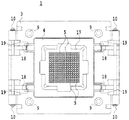
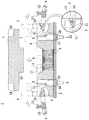
図1および図2は、本発明におけるICソケットのコンタクトピンの交換方法を実施するための実施例1を図示、説明するためのICソケットを示す平面図および中央縦断面図である。
【0018】
図1および図2に示されるように、本発明が適用されるICソケット1は、プリント基板2に固着された枠体3と、この枠体3に着脱自在に装着されるソケットブロック4と、このソケットブロック4に装着される多数のコンタクトピン5と、ソケットブロック4に設けられた弾性変位可能な錠止アーム6と、ソケットブロック4に装着されるICパッケージ等の電気部品Hと、ソケットブロック4の上に載置される押え板7と、押え板7をソケットブロック4に保持する押え板保持部材8と、ソケットブロック4を枠体3に離脱可能に錠止する錠止爪18を含む錠止手段とを有しており、コンタクトピン5の上にICパッケージ等の電気部品Hが置かれて押え板7が配置され、押え板保持部材8によって保持されるように構成されている。
【0019】
枠体3は中央に空所を有するようにほぼ四角形の枠状に形成され、四隅においてボルト9によってプリント基板2に固着されており、左右両側部に一対宛ての押え板保持部材8が軸10によってそれぞれ枢動可能に設けられると共に、内側に向ってほぼ水平横方向に移動可能に設けられており、この押え板保持部材8の内側端に設けられているフィンガー状の押圧部11が錠止アーム6を内方に向って押圧することによって変位できるようになっている。また、これら押え板保持部材8は、それぞれ上方部分にほぼ直角に延びて突出する係止アーム12が設けられており、この係止アーム12に係止爪13が設けられていて、押え板7の係止溝14に係合されるように形成されている。
【0020】
ソケットブロック4は、中央部分にコンタクトピン5のための多数の孔16が整列して設けられており、各々の孔16の中にコンタクトピン5がそれぞれ挿入されていて、対応するプリント基板2のコンタクトと接続できるようになっている。さらに、ソケットブロック4の中央部分には窪み部17が設けられており、この窪み部17内にICパッケージH等の電気部品が配置されて、押え板7の突出部15がICパッケージHを軽く押圧して保持できるべく配置されるようになっている。さらにまた、ソケットブロック4の錠止アーム6は、ソケットブロック4の上面から先ず外方に延び、次いで、下方にほぼ直角に屈曲して垂直な状態に延びており、その先端部分には外側に向って突出する錠止爪18が設けられていて、枠体3に対応するように設けられた突部19と係合できるようになっている。
【0021】
従って、枠体3の中央の空所部分内にソケットブロック4を収容するように挿入して、錠止アーム6の錠止爪18を枠体3の突部19と係合させることによってソケットブロック4を枠体3の装着することができるし、錠止アーム6を内方に変位して錠止爪18を突部19から離し、ソケットブロック4を上方に引き上げれば、ソケットブロック4を枠体3から取り出すことができ、これら錠止アーム6の錠止爪18と枠体3の突部19とによって錠止手段が形成されており、錠止爪18と突部19との係合、離脱によって錠止手段の錠止と解錠とが行なわれるようになっている。
【0022】
また、枠体3には、図2に拡大して示されるように押え板保持部材8の軸10が移動するための横方向にほぼ水平に延びる切欠き通路20が形成されており、この切欠き通路20内に、互いに内側に向って突出する一対の突起21が設けられていて、この切欠き通路20内において押え板保持部材8が軸10を中心として回動しようとする時に、これら突起21が軸10の止めとなって作用して軸10を支え、押え板保持部材8の軸10を中心とした回動を円滑にできるようにしている。従って、押え板保持部材8は軸10を中心として内側に向って起立した状態に回動することができ、ソケットブロック4上に載置された押え板7の係止溝14に係止爪13を係合させることによって押え板7を固定、保持することができる。
【0023】
このように、本発明が適用されるICソケット1は、ソケットブロック4が装着される枠体3が複数個のボルト9によってプリント基板2に固着され、この枠体3に、錠止アーム6の錠止爪18と枠体3の突部19とから構成される錠止手段によってソケットブロック4が着脱可能に装着できる。また、ソケットブロック4には多数のコンタクトピン5が配設されており、これらコンタクトピン5の上にICパッケージHを配置して押え板7を載せて、押え板保持部材8をほぼ垂直な状態にまで軸10周りに回動して係止爪13を係止溝14に係合させることによって、ICソケット1を一体的に組み立てることができる。
【0024】
このように構成された本発明のICソケットにおけるコンタクトピンの一括交換に就いて以下に説明する。
【0025】
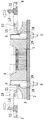
本発明において、汚れや損傷、または他の何等かの理由によってコンタクトピン5をソケットブロック4ごと全て取り出して交換する場合には、先ず、図2に示されるように、左右両側の押え板保持部材8をそれぞれ軸10周りに外方に回動して係止アーム12の係止爪13を押え板7の係止溝14から外して、押え板7を矢印で示されるように上方に引き上げてソケットブロック4から取り外す。そして、押え板7から外した押え板保持部材8は、そのままほぼ水平な状態に支持し、次いで、図3に示されるように、押え板保持部材8を、矢印で示されるように、内方に向って押して、押え板保持部材8のフィンガー状の押圧部11によってソケットブロック4の錠止アーム6を内側に向って弾性変位させれば、錠止手段としての錠止アーム6の錠止爪18が、枠体3の突部19から離れて図4に示される状態になる。
【0026】
次いで、この状態からソケットブロック4を図5の矢印で示されるように、上方に引き上げれば、ソケットブロック4を枠体3から取り出すことができるのでコンタクトピン5をソケットブロック4ごと一緒に、一括して交換することができる。従って、交換すべき新たなコンタクトピン5が装着された新しいソケットブロック4を枠体3内に組み入れることによって、枠体3の突部19にソケットブロック4の錠止アーム6の先端の錠止爪18が係合されて錠止されて枠体3にソケットブロック4が固持されるので、新たなコンタクトピン5を有するソケットブロック4をプリント基板2上の枠体3に組み込むことができる。
【0027】
上記のように構成された本発明が適用されるICソケット1において、ソケットブロック4に装着されるコンタクトピン5の全てを交換する場合には、ソケットブロック4とコンタクトピン5をブロックごと取外すので、大量のコンタクトピン5を全部一度に一括して交換することができ、しかも簡単に行うことができるので、コンタクトピン5のソケットブロック4ごとの交換を一括して適切に短時間に行なうことができ、経済的である。
【0028】
【発明の効果】
以上説明したように、本発明の請求項1記載のICソケットのコンタクトピンの交換方法は、プリント基板に固着された枠体と、該枠体に取外し可能に取付けられるソケットブロックと、該ソケットブロック内に配設されるコンタクトピン上に装着されるICパッケージと、前記ソケットブロックとコンタクトピン上に載置される押え板とを有するICソケットのコンタクトピンの交換方法において、
前記枠体に枢支された前記押え板保持部材が、前記枠体に軸回りに回動可能に支持されると共に横方向に滑動可能に枢支され、前記ソケットブロックに形成された弾性変位可能な錠止アームを押圧して前記ソケットブロックを前記枠体に取外し可能に錠止する錠止手段を解錠できるので、沢山のコンタクトピンを全部一度に一括して交換することができ、しかも簡単に行うことができると共に、コンタクトピンをソケットブロックごと短時間に交換を行なうことができ、経済的であり、押え板の保持と錠止手段の解錠との2つの操作を兼用でき、構成を簡略化することができる。
【0032】
本発明の請求項2記載のICソケットのコンタクトピンの交換方法は、前記押え板保持部材を枢支する軸が、前記枠体の横方向の切欠き通路内に保持されると共に、該切欠き通路に沿って移動できるので、好適に構成することができ、簡略化することができる。
【0033】
本発明の請求項3記載のICソケットは、プリント基板に固着された枠体と、該枠体に取外し可能に取付けられるソケットブロックと、該ソケットブロックに配設されるコンタクトピン上に装着されるICパッケージと、前記ソケットブロックとコンタクトピン上に載置される押え板と、前記ソケットブロックを前記枠体に離脱可能に錠止する錠止手段と、前記ソケットブロック上に前記押え板を取外し可能に保持するように前記枠体に枢支された押え板保持部材とを有するICソケットにおいて、
前記押え板保持部材が、前記枠体に軸回りに回動可能に支持されると共に横方向に滑動可能に枢支され、前記ソケットブロックに形成された弾性変位可能な錠止アームを押圧して前記錠止手段を解錠できるので、前記枠体から前記ソケットブロックを取外して、沢山のコンタクトピンを全部一度に一括して交換することができ、しかも簡単に行うことができると共に、コンタクトピンをソケットブロックごと短時間に交換を行なうことができ、経済的であり、押え板の保持と錠止手段の解錠との2つの操作を兼用でき、構成を簡略化することができる。
【0037】
本発明の請求項4記載のICソケットは、前記押え板保持部材を枢支する軸が、前記枠体の横方向の切欠き通路内に保持されると共に、該切欠き通路に沿って移動できるので、好適に構成することができ、簡略化することができる。
【図面の簡単な説明】
【図1】本発明のICソケットのコンタクトピンの交換方法が実施されるICソケットの平面図である。
【図2】図1のICソケットの中央縦断面図である。
【図3】本発明のICソケットの交換方法の実施例1におけるソケットブロックの錠止を解除する前の中央縦断面図である。
【図4】図3の本発明のICソケットにおけるソケットブロック錠止機構を解除する時の中央縦断面図である。
【図5】図3の本発明のICソケットにおけるソケットブロック錠止機構を解除してソケットブロックを引き上げた時の中央縦断面図である。
【符号の説明】
1 ICソケット
2 プリント基板
3 枠体
4 ソケットブロック
5 コンタクトピン
6 錠止アーム
7 押え板
8 押え板保持部材
9 ボルト
10 軸
11 押圧部
12 係止アーム
13 係止爪
14 係止溝
15 突出部
16 孔
17 窪み部
18 錠止爪
19 突部
20 切欠き通路
21 突起[0001]
BACKGROUND OF THE INVENTION
The present invention relates to a method for exchanging contact pins of an IC socket, and more particularly to a method for collectively exchanging contact pins used for an IC socket while the IC socket is mounted without being removed from a printed circuit board. .
[0002]
[Prior art]
2. Description of the Related Art Conventionally, in an IC package or the like as an electrical component, an IC package having an IC socket in which a socket block having contact pins mounted on a frame fixed to a printed board is held by a holding plate is known. .
[0003]
[Problems to be solved by the invention]
In such a conventional IC package, when exchanging contact pins, the IC pins must be removed from the printed board and the contact pins must be exchanged.
[0004]
Therefore, it is troublesome to remove the IC socket from the printed board and replace the contact pins, which is time consuming and troublesome.
[0005]
Accordingly, an object of the present invention is to provide a method for replacing contact pins of an IC socket, in which contact pins can be replaced at a time even when a printed circuit board is mounted in order to solve such a conventional problem. It is to provide.
[0006]
[Means for Solving the Problems]
In order to achieve the above-described object, a method for replacing contact pins of an IC socket according to the present invention includes a frame fixed to a printed circuit board, a socket block removably attached to the frame, and a socket block. In an IC socket contact pin replacement method having an IC package mounted on a contact pin to be disposed, and the socket block and a presser plate placed on the contact pin, the IC pin is pivotally supported by the frame body. The holding plate holding member is supported by the frame body so as to be pivotable about an axis and is pivotally supported so as to be slidable in a lateral direction, and presses an elastically displaceable locking arm formed on the socket block. The locking means for detachably locking the socket block to the frame body can be unlocked.
[0010]
In the IC socket contact pin replacement method according to the present invention, the shaft for pivotally supporting the holding plate holding member is held in the notch passage in the lateral direction of the frame body, and is along the notch passage. It is possible to move.
[0011]
Further, an IC socket of the present invention includes a frame body fixed to a printed circuit board, a socket block that is detachably attached to the frame body, and an IC package that is mounted on a contact pin disposed in the socket block. A holding plate placed on the socket block and the contact pin, locking means for releasably locking the socket block to the frame, and a holding plate detachably held on the socket block. An IC socket having a holding plate holding member pivotally supported by the frame body,
The holding plate holding member is supported by the frame body so as to be pivotable about an axis and is pivotally supported so as to be slidable in a lateral direction, and presses an elastically displaceable locking arm formed on the socket block. The locking means can be unlocked.
[0015]
Furthermore, the IC socket according to the present invention is characterized in that the shaft for pivotally supporting the holding plate holding member is held in the notch passage in the lateral direction of the frame body and can move along the notch passage. And
[0016]
Other objects, features and advantages of the present invention will become apparent from the following detailed description of the embodiments of the present invention illustrated in the accompanying drawings.
[0017]
DETAILED DESCRIPTION OF THE INVENTION
(Example 1)
FIG. 1 and FIG. 2 are a plan view and a central longitudinal sectional view showing an IC socket for illustrating and explaining a first embodiment for carrying out a method for replacing a contact pin of an IC socket according to the present invention.
[0018]
As shown in FIGS. 1 and 2, an
[0019]
The
[0020]
The socket block 4 is provided with a large number of
[0021]
Accordingly, the socket block 4 is inserted into the space in the center of the
[0022]
Further, as shown in an enlarged view in FIG. 2, the
[0023]
As described above, in the
[0024]
The collective exchange of contact pins in the IC socket of the present invention configured as described above will be described below.
[0025]
In the present invention, when all of the contact pins 5 are taken out and replaced together with the socket block 4 due to dirt or damage, or for some other reason, first, as shown in FIG. 8 is pivoted outwardly around the
[0026]
Next, if the socket block 4 is pulled upward from this state as shown by the arrow in FIG. 5, the socket block 4 can be taken out from the
[0027]
In the
[0028]
【The invention's effect】
As described above, the method of replacing the contact pin of the IC socket according to
The presser plate holding member pivotally supported by the frame body is supported by the frame body so as to be pivotable about an axis and is pivotally supported so as to be slidable in the lateral direction, and is elastically displaceable formed on the socket block. Since the locking means for detachably locking the socket block by pressing the appropriate locking arm can be unlocked, a large number of contact pins can be exchanged all at once and easily The contact pin can be exchanged for each socket block in a short time, which is economical and can be used for both the holding of the holding plate and the unlocking of the locking means. It can be simplified.
[0032]
According to a second aspect of the present invention, there is provided a method for exchanging contact pins of an IC socket, wherein a shaft for pivotally supporting the holding plate holding member is held in a notch passage in a lateral direction of the frame body, and the notch Since it can move along a passage, it can constitute suitably and can be simplified.
[0033]
An IC socket according to a third aspect of the present invention is mounted on a frame fixed to a printed circuit board, a socket block removably attached to the frame, and a contact pin disposed in the socket block. IC package, holding plate placed on the socket block and contact pin, locking means for releasably locking the socket block to the frame, and the holding plate can be removed on the socket block In an IC socket having a holding plate holding member pivotally supported by the frame body so as to hold
The holding plate holding member is supported by the frame body so as to be pivotable about an axis and is pivotally supported so as to be slidable in a lateral direction, and presses an elastically displaceable locking arm formed on the socket block. Since the locking means can be unlocked, the socket block can be removed from the frame body, and a large number of contact pins can be exchanged all at once. The socket block can be exchanged in a short time, which is economical, can be used for both the holding of the holding plate and the unlocking of the locking means, and the configuration can be simplified.
[0037]
In the IC socket according to claim 4 of the present invention, the shaft for pivotally supporting the presser plate holding member is held in the notch passage in the lateral direction of the frame body and can move along the notch passage. Therefore, it can be suitably configured and can be simplified.
[Brief description of the drawings]
FIG. 1 is a plan view of an IC socket in which a method for exchanging contact pins of an IC socket according to the present invention is performed.
2 is a central longitudinal sectional view of the IC socket of FIG. 1. FIG.
FIG. 3 is a central longitudinal sectional view before unlocking the socket block in the first embodiment of the IC socket replacement method of the present invention.
4 is a central longitudinal cross-sectional view when releasing the socket block locking mechanism in the IC socket of the present invention of FIG. 3; FIG.
5 is a central longitudinal sectional view when the socket block locking mechanism in the IC socket of the present invention of FIG. 3 is released and the socket block is pulled up. FIG.
[Explanation of symbols]
DESCRIPTION OF
Claims (4)
前記枠体に枢支された前記押え板保持部材が、前記枠体に軸回りに回動可能に支持されると共に横方向に滑動可能に枢支され、前記ソケットブロックに形成された弾性変位可能な錠止アームを押圧して前記ソケットブロックを前記枠体に取外し可能に錠止する錠止手段を解錠できることを特徴とするICソケットのコンタクトピンの交換方法。A frame fixed to a printed circuit board; a socket block removably attached to the frame; an IC package mounted on a contact pin disposed in the socket block; and the socket block and the contact pin In the replacement method of the contact pin of the IC socket having the presser plate placed on
The presser plate holding member pivotally supported by the frame body is supported by the frame body so as to be pivotable about an axis and is pivotally supported so as to be slidable in the lateral direction, and is elastically displaceable formed on the socket block. A method of exchanging contact pins of an IC socket, wherein the locking means for pressing the lock arm to removably lock the socket block to the frame can be unlocked.
前記押え板保持部材が、前記枠体に軸回りに回動可能に支持されると共に横方向に滑動可能に枢支され、前記ソケットブロックに形成された弾性変位可能な錠止アームを押圧して前記錠止手段を解錠できることを特徴とするICソケット。A frame fixed to a printed circuit board; a socket block removably attached to the frame; an IC package mounted on a contact pin disposed on the socket block; and the socket block and the contact pin The holding plate to be placed, the locking means for releasably locking the socket block to the frame body, and the frame block so as to be removably held by the socket block. In an IC socket having a holding plate holding member,
The holding plate holding member is supported by the frame body so as to be pivotable about an axis and is pivotally supported so as to be slidable in a lateral direction, and presses an elastically displaceable locking arm formed on the socket block. An IC socket characterized in that the locking means can be unlocked.
Priority Applications (1)
| Application Number | Priority Date | Filing Date | Title |
|---|---|---|---|
| JP2001037202A JP3606375B2 (en) | 2001-02-14 | 2001-02-14 | IC socket contact pin replacement method and IC socket |
Applications Claiming Priority (1)
| Application Number | Priority Date | Filing Date | Title |
|---|---|---|---|
| JP2001037202A JP3606375B2 (en) | 2001-02-14 | 2001-02-14 | IC socket contact pin replacement method and IC socket |
Publications (2)
| Publication Number | Publication Date |
|---|---|
| JP2002243794A JP2002243794A (en) | 2002-08-28 |
| JP3606375B2 true JP3606375B2 (en) | 2005-01-05 |
Family
ID=18900368
Family Applications (1)
| Application Number | Title | Priority Date | Filing Date |
|---|---|---|---|
| JP2001037202A Expired - Fee Related JP3606375B2 (en) | 2001-02-14 | 2001-02-14 | IC socket contact pin replacement method and IC socket |
Country Status (1)
| Country | Link |
|---|---|
| JP (1) | JP3606375B2 (en) |
Families Citing this family (2)
| Publication number | Priority date | Publication date | Assignee | Title |
|---|---|---|---|---|
| JP4471941B2 (en) | 2005-03-10 | 2010-06-02 | 山一電機株式会社 | Socket for semiconductor device |
| JP4231067B2 (en) | 2006-07-28 | 2009-02-25 | 山一電機株式会社 | Socket for semiconductor device |
Family Cites Families (2)
| Publication number | Priority date | Publication date | Assignee | Title |
|---|---|---|---|---|
| JPS63128679U (en) * | 1987-02-16 | 1988-08-23 | ||
| JPH07254468A (en) * | 1994-03-15 | 1995-10-03 | Sony Corp | Ic measuring socket |
-
2001
- 2001-02-14 JP JP2001037202A patent/JP3606375B2/en not_active Expired - Fee Related
Also Published As
| Publication number | Publication date |
|---|---|
| JP2002243794A (en) | 2002-08-28 |
Similar Documents
| Publication | Publication Date | Title |
|---|---|---|
| JPH0530034B2 (en) | ||
| US7503772B2 (en) | Socket for semiconductor device | |
| JP3606375B2 (en) | IC socket contact pin replacement method and IC socket | |
| US5364286A (en) | Contacting condition maintaining device for use in an electric part socket | |
| JP3655398B2 (en) | Component mounting equipment | |
| JP2004181608A (en) | Polishing jig for ferrule end surface with optical fiber polishing machine | |
| KR101505955B1 (en) | Opening apparatus for test handler | |
| JPH10144274A (en) | Battery mounting/demounting structure | |
| CN209879069U (en) | Optical module unblock reset structure | |
| US20050181662A1 (en) | Printed circuit board module and disconnect bow | |
| JPS6240375Y2 (en) | ||
| JP4258635B2 (en) | Mold removal tool | |
| JP4208161B2 (en) | IC socket operation mechanism | |
| JPH09293565A (en) | Electric connector with base board locking part and manufacture thereof | |
| JP3706333B2 (en) | Latch lock mechanism of KGD carrier | |
| JP2742523B2 (en) | IC socket | |
| JP3818041B2 (en) | IC socket | |
| JP4064968B2 (en) | Component mounting equipment | |
| CN218877360U (en) | Folding supporting plate | |
| JP4319305B2 (en) | IC socket | |
| JPH10249439A (en) | Upper die in press machine | |
| JP2011106185A (en) | Removing device for lattice-like ditch cover | |
| CN116409058A (en) | Liquid droplet discharge device and method for manufacturing the same | |
| JP2004506341A (en) | Operating member for attaching and detaching a flat module, provided with a locking member that locks in at least three switching positions, front member for the flat module equipped with the operating member, and module support for attaching the flat module | |
| JPH064637Y2 (en) | Water cooling jacket retention mechanism |
Legal Events
| Date | Code | Title | Description |
|---|---|---|---|
| A977 | Report on retrieval |
Free format text: JAPANESE INTERMEDIATE CODE: A971007 Effective date: 20031208 |
|
| A131 | Notification of reasons for refusal |
Free format text: JAPANESE INTERMEDIATE CODE: A131 Effective date: 20031219 |
|
| A521 | Request for written amendment filed |
Free format text: JAPANESE INTERMEDIATE CODE: A523 Effective date: 20040217 |
|
| TRDD | Decision of grant or rejection written | ||
| A01 | Written decision to grant a patent or to grant a registration (utility model) |
Free format text: JAPANESE INTERMEDIATE CODE: A01 Effective date: 20040914 |
|
| RD04 | Notification of resignation of power of attorney |
Free format text: JAPANESE INTERMEDIATE CODE: A7424 Effective date: 20040929 |
|
| A61 | First payment of annual fees (during grant procedure) |
Free format text: JAPANESE INTERMEDIATE CODE: A61 Effective date: 20040929 |
|
| R150 | Certificate of patent or registration of utility model |
Free format text: JAPANESE INTERMEDIATE CODE: R150 |
|
| FPAY | Renewal fee payment (event date is renewal date of database) |
Free format text: PAYMENT UNTIL: 20071015 Year of fee payment: 3 |
|
| FPAY | Renewal fee payment (event date is renewal date of database) |
Free format text: PAYMENT UNTIL: 20081015 Year of fee payment: 4 |
|
| LAPS | Cancellation because of no payment of annual fees |