JP3602139B2 - Position determination method and device - Google Patents
Position determination method and device Download PDFInfo
- Publication number
- JP3602139B2 JP3602139B2 JP52491996A JP52491996A JP3602139B2 JP 3602139 B2 JP3602139 B2 JP 3602139B2 JP 52491996 A JP52491996 A JP 52491996A JP 52491996 A JP52491996 A JP 52491996A JP 3602139 B2 JP3602139 B2 JP 3602139B2
- Authority
- JP
- Japan
- Prior art keywords
- ring
- marker
- cast
- skin
- internal injury
- Prior art date
- Legal status (The legal status is an assumption and is not a legal conclusion. Google has not performed a legal analysis and makes no representation as to the accuracy of the status listed.)
- Expired - Fee Related
Links
Images


Classifications
-
- A—HUMAN NECESSITIES
- A61—MEDICAL OR VETERINARY SCIENCE; HYGIENE
- A61B—DIAGNOSIS; SURGERY; IDENTIFICATION
- A61B17/00—Surgical instruments, devices or methods
- A61B17/22—Implements for squeezing-off ulcers or the like on inner organs of the body; Implements for scraping-out cavities of body organs, e.g. bones; for invasive removal or destruction of calculus using mechanical vibrations; for removing obstructions in blood vessels, not otherwise provided for
-
- A—HUMAN NECESSITIES
- A61—MEDICAL OR VETERINARY SCIENCE; HYGIENE
- A61B—DIAGNOSIS; SURGERY; IDENTIFICATION
- A61B6/00—Apparatus or devices for radiation diagnosis; Apparatus or devices for radiation diagnosis combined with radiation therapy equipment
- A61B6/12—Arrangements for detecting or locating foreign bodies
-
- A—HUMAN NECESSITIES
- A61—MEDICAL OR VETERINARY SCIENCE; HYGIENE
- A61B—DIAGNOSIS; SURGERY; IDENTIFICATION
- A61B90/00—Instruments, implements or accessories specially adapted for surgery or diagnosis and not covered by any of the groups A61B1/00 - A61B50/00, e.g. for luxation treatment or for protecting wound edges
- A61B90/39—Markers, e.g. radio-opaque or breast lesions markers
-
- A—HUMAN NECESSITIES
- A61—MEDICAL OR VETERINARY SCIENCE; HYGIENE
- A61N—ELECTROTHERAPY; MAGNETOTHERAPY; RADIATION THERAPY; ULTRASOUND THERAPY
- A61N7/00—Ultrasound therapy
Landscapes
- Health & Medical Sciences (AREA)
- Life Sciences & Earth Sciences (AREA)
- Surgery (AREA)
- Medical Informatics (AREA)
- Engineering & Computer Science (AREA)
- Nuclear Medicine, Radiotherapy & Molecular Imaging (AREA)
- Biomedical Technology (AREA)
- Heart & Thoracic Surgery (AREA)
- Veterinary Medicine (AREA)
- Molecular Biology (AREA)
- Animal Behavior & Ethology (AREA)
- General Health & Medical Sciences (AREA)
- Public Health (AREA)
- Pathology (AREA)
- Biophysics (AREA)
- Oral & Maxillofacial Surgery (AREA)
- High Energy & Nuclear Physics (AREA)
- Optics & Photonics (AREA)
- Radiology & Medical Imaging (AREA)
- Physics & Mathematics (AREA)
- Orthopedic Medicine & Surgery (AREA)
- Vascular Medicine (AREA)
- Surgical Instruments (AREA)
- Vehicle Body Suspensions (AREA)
- Magnetic Resonance Imaging Apparatus (AREA)
- Ultra Sonic Daignosis Equipment (AREA)
- Percussion Or Vibration Massage (AREA)
- Apparatus For Radiation Diagnosis (AREA)
- Electrical Discharge Machining, Electrochemical Machining, And Combined Machining (AREA)
- Variable-Direction Aerials And Aerial Arrays (AREA)
- Auxiliary Devices For And Details Of Packaging Control (AREA)
- Mechanical Treatment Of Semiconductor (AREA)
- Die Bonding (AREA)
- Seal Device For Vehicle (AREA)
Abstract
Description
発明の背景
1.発明の分野
本発明は、筋骨格の負傷を超音波により治療および/又は診断するための装置および方法に関する。超音波治療法は、特に骨折、断裂、変形などの骨および筋肉の怪我の回復を促進させるのに適しており、また他の怪我に対しても適用可能である。
2.関連技術の説明
骨の負傷に対して診断および治療を行うあたり、治療学的に超音波を使用することが知られている。骨の負傷部付近の適切な表面位置において適切な条件下で適量の超音波を適用することにより、有害な効果を伴うことなく自然治癒が促進される。超音波治療法は、治癒能力が低い患者、例えば老人などに対しても、補綴による代用が必要な骨の負傷や患者を回復不能な身障者にしてしまうような骨の負傷の治癒を促進させる。
デュアルテ(Duarte)のUS特許4,530,360には、骨の負傷部付近の皮膚に装着された作用面から超音波パルスを付加するという基本的な治療技術および装置が記述されている。この超音波供給装置の「作用面」(この出願で使用されていた用語)は、周囲の物体に超音波を伝達する露出された有体物の表面を指している。トランスデューサーの表面が露出されている装置であれば、作用面はそのトランスデューサーの表面となる。デュアルテは、超音波を発生させるRF信号の範囲、超音波の出力密度のレベル、各超音波パルスの持続値域、超音波パルスの周波数範囲についても述べている。さらに、日常的な治療時間についても言及している。
タリシュ(Talish)とリフシー(Lifshey)のUS特許5,003,965と5,186,162(以下、タリシュの特許965、タリシュの特許162として示す。)には、RF発生器とトランスデューサーの両方の備えたモジュール式のアプリケーターユニットを有する超音波供給装置であって、このアプリケーターユニットを皮膚上に接触させて使用するものが記述されている。超音波パルスの持続時間とそのパルスの反復周波数を制御する信号は、アプリケーターユニットとは別に生成される。タリシュの特許965と特許162では、作用面を皮膚に接触させて装着するためのアプリケーターユニットの固定装置についても記述されている。タリシュの特許965と162では皮膚はギプスで覆われているが、タリシュとリフシーのUS特許5,211,160(以下、タリシュの特許160として示す。)では固定装置は覆われていない状態の人体に装着する場合(例えば、ギプス、その他の医療用包帯がない場合)について記述されている。さらに、タリシュの特許160では、アプリケーターユニットの種々の改善例についても記述されている。
デュアルテの特許、タリシュの特許965、162および160は、すべて本願に包含されるものである。
上記文献において記述されたシステムは、当業者にとって基本的な治療法および装置を開示するものであるが、これらには作用面を治療に際して皮膚に接触させて配置する方法および装置については開示していない。作用面を皮膚の表面位置に適切に配置すれば、超音波治療によってもたらされる効果が向上する。作用面が正確に配置されていなかったとすれば、負傷部に伝達される超音波が弱まってしまい、治癒時間が意図したほどには短縮されないこととなる。
そこで、本願の目的は、体内の負傷部に対応した表面位置を決定するための方法および装置を提供することにある。この表面位置には皮膚上、ギプス、その他の医療用包帯上の位置が含まれる。また、本願の他の目的は、体内の負傷、特に筋骨格の負傷部に対応する皮膚上の位置で超音波治療を施すことができる方法を提供することにある。
発明の概略
上記目的を達成するために、本発明は、筋骨格の負傷部に対応する表面位置を決定するための装置であって、体内の負傷部付近の表面位置に取り外し可能に配置され、少なくともその一部が、体内の負傷を透視する手段をもって少なくとも部分的に視認できる材料で形成されているマーカーを備えた装置を含むものである。負傷の透視には例えばX線が使用され、この場合、マーカーはX線で視認できる材料、例えばステンレス鋼で形成される。
また、本発明は、体内の負傷部に対応する表面位置を決定するための方法であって、マーカーを体内の負傷部付近の表面位置に配置し、マーカーと体内の負傷とを同時に透視し、体内の負傷部に対する近接表面位置に印を付する工程からなる方法を含むものである。X線がマーカーと体内の負傷を同時に透視するのに使用される場合、X線画像は体内の負傷部付近の表面位置を位置づけるために使用される。
さらに、本発明は、体内の負傷に対応する皮膚上の位置に超音波処置を施す方法であって、マーカーを体内の負傷部付近の表面位置に配置し、マーカーと体内の負傷とを同時に透視し、体内の負傷部に対する近接表面位置に印を付し、超音波発生システムの作用面を体内の負傷部に対する皮膚上の近接位置に配置する工程からなる方法を含むものである。皮膚がギプスや医療用包帯で覆われている場合、まずそのギプスや医療用の包帯の上に、体内の負傷部に対する近接表面位置を決定する。そして、ギプス又は医療用包帯の一部を取り除き、内部の負傷部に対する皮膚上の近接位置を露出させる。これによって、作用面を皮膚に接触させることができる。
【図面の簡単な説明】
本願の好ましい実施例について、以下の図面を参照して説明する。
図1は、位置合わせリングとストラップの斜視図である。
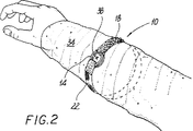
図2は、ギプスで覆われた四肢に装着した位置合わせリングとストラップの斜視図である。
図3は、ギプス上のマークに中心を合わせて配置された型板の斜視図である。
図4は、一部が除去されたギプスと、超音波治療モジュールを保持および配置する固定具の分解図である。
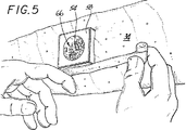
図5は、一部が除去されたギプスに装着された固定具の斜視図である。
図6は、ギプスと、固定具と、固定具のためのキャップの斜視図である。
図7は、固定具に対して配列された治療モジュールの分解斜視図である。
図8は、裸の四肢に装着された固定具の分解斜視図である。
図9は、裸の四肢に装着された固定具と治療モジュールの分解斜視図である。
好ましい実施例の詳細な説明
図1は、2個の部材18,22からなるストラップを備えた位置合わせリング14を有する本願に係る装置10を示す。リング14は、使用される医療用の透視システムで視認できる素材で成形されている。したがって、X線が使用された場合でも、リング14の少なくとも一部がX線の透過を妨げる。また、赤外線が使用された場合でも、リング14の少なくとも一部が赤外線の透過を妨げる。さらに、磁気共鳴撮像を行う場合でも、リング14の少なくとも一部が常磁性とされる。
図1のリング14の寸法は、対象物の大きさ、傷の位置と大きさ、使用される透視システムに応じて設定されている。平均的な人間の四肢の骨折について、X線、赤外線および磁性共鳴撮像を使用する透視システムを使用する場合、リングは直径が通常1.5インチとされ、断面直径が通常0.2インチである金属材質の硬質な円環体とされる。上記設定において透視システムが超音波を使用する場合、リングは、配置される表面の輪郭に適応できるように実際には柔軟性を有する平面状に形成され、その表面とリングを横切ってトランスデューサーを移動させることができる。
図1のストラップは2個の部材18,22からなり、これらはリング14に繋がれている。2個の部材18,22はフックとループからなるタイプの連結具(面ファスナー)となっているので、接続可能である。なお、他の連結手段又は調整手段でも代用可能である。
図2から図7は、本願の方法における一連の手順を示す。以下、医療用透視システムとしてX線を使用するものとして説明するが、上述した他のシステムにも容易に適用できる。
図2は、ギプス34で覆われた四肢に装着された図1の装置10を示す。位置合わせリング14は、最初は骨折箇所に一致するようにギプス34上に配置されている。この初期位置は、骨折箇所に対する仮の推定位置であって、以前に行われたX線写真や医師や患者による傷の箇所についての記憶に基づいて決められる。
骨折部に対する外部からのX線撮影は、位置合わせリング14を含めて行われる。位置合わせリング14の初期位置は体内の負傷に対する仮の推定位置であるが、多くの場合、最初の配置は十分に正確であるので、X線によってリング14の枠内を通じて体内の負傷を視認することができる。
X線写真には、位置合わせリング14に対する骨折位置が示される。このX線写真を指標として使用し、その時点の位置合わせリング14との関係からギプス上の対応位置にマーク38を付ける。マーク38は、骨折部に対するギプス上の近接表面位置を示す。より精度を高めるためには、リング14の中心をマーク38に合わせ、再度X線により撮影を行い、このX線写真上のリングに対する骨折位置に新しいマーク(図示せず)をギプス上に付ける。位置合わせリング14の再設定およびX線撮影を続けて繰り返すことによって精度を高めることができる。
図3に示すように、方形状の型板42をギプス34に押し当てて、その中心を骨折箇所に対応するギプス34上の表面位置であるマーク38に合わせる。型板の内側縁の形状に沿って線でなぞり、なぞった部分を取り除いて、図4に示すようにギプスの開口を通じて皮膚を露出させる。また、図4に示すように、ギプスの除去部分に、ギプスとほぼ同じ厚さのフェルト製パッド50を収納する。このパッド50は、円柱状のフェルト製のパッド54を収納する円柱状の穴を有している。型板42とこれに従って設けられたギプスの開口46は、超音波治療モジュールを保持および配置するための固定具58のフランジ62よりも小さいので、フランジ62は開口46に装着されるとこの開口46を形成するギプス表面に係合する。固定具58は、円形の孔66と剣状のロック突起70を有している。孔66は、円柱状のフェルト製パッド54と同一の外径となっている。
図5は、ギプス34の開口に配置された固定具58とフェルト製パッド50を示し、孔66に対して円柱状のフェルト製パッド54が同心に配列されている。フランジ62(図4参照)がギプス34と係合しているので、固定具58がフェルト製パッド50(図4参照)を皮膚に圧着させ、これによって、除去されたギプスにほぼ等しい圧力がフェルト製パッドが接する皮膚に付加される。
図6は、日常の超音波治療が終了したときに使用される固定具58のキャップシステムを示す。キャップ74は、固定具58の孔66に挿入される円柱状部78を有している。キャップ74はその円柱状部78に、固定具58の剣状突起70に係合する溝状突起82を有している。円柱状のフェルト製パッド54は孔66の内部に配置され、円柱状部78が溝状突起82が剣状突起70からずれた状態で孔66に挿入される。溝状突起82は、キャップ74を固定具58に対して所定の深さに位置させるように構成されている。これによって、フェルト製パッド54に正確な圧力が付加される。キャップ74と円柱状フェルト製パッド54によって皮膚に作用する圧力がギプス34による圧力に近づくように、フェルト製パッド54に対してキャップ74が押し付けられることになる。その箇所の領域浮腫の発生を防止するためにキャップ74で固定具が閉じると、このパッド54は皮膚に対して圧力を付加する。(フェルト製パッドの厚さとこれに基づく皮膚に対する圧力を調整すべく、フェルト製のパッド54は1層ごとにはがせる平面円形状の複数の層で構成してもよい。)そして、キャップ74を回転させて、溝状突起82を剣状突起70に係合させる。
図7は、治療モジュール90と固定具58の分解斜視図である。モジュール突出部94は、固定具58の外表面側付近に配置された剣状突起70に係合する溝状突起98を備えている。キャップ74と円柱状のフェルト製パッド54(図6参照)を取り外し、モジュール突出部94を固定具58の孔66(およびフェルト製パッド50の径)に合わせ、溝状突起98が剣状突起70からずれた状態で挿入する。モジュール90の作用面102が皮膚106に接触すると、モジュール90を回転させて溝状突起98を剣状突起70に係合させる。溝状突起98は、治療モジュール90を固定具58に対して所定の深さに位置させるように構成されている。そして、超音波処置を開始する。
作用面102は、固定具58に挿入されて皮膚106に接触するのに先だって、結合ゲルで被覆されている。ゲルは、ゲルサック、ゲル袋状体、その他の容器を使用して作用面102に塗布される。
図8は、本発明の他の変形例を示し、ストラップ114を用いて裸の四肢に固定具106を取り付けるものである。ストラップ114がきつく締められたとき、固定具106の放射状フランジ118が皮膚に接触し、発泡材の裏面122を圧着させる。
固定具106は、上述したような方法によって骨折部に対する皮膚上の近接位置に配置されている。すなわち、位置合わせリングを四肢の負傷部付近の皮膚に直接装着し、傷とリングとをX線で撮影し、このX線写真に基づいて傷とリングの位置関係から骨折部に対する皮膚上の近接位置に印をつける。
この皮膚上の近接位置には、例えば一時的ないれずみ又はマジックマーカーを使用した永久的ではないマークが付けられる。したがって、治療がないときは固定具106を外し、超音波治療のために再び適正に装着すればよい。
図9は、裸の四肢110に使用される治療モジュール134と固定具106の分解斜視図である。上述と同様に、モジュール突出部138は固定具106の孔126にはめ込まれる。超音波治療のためのモジュール134の配置は上述したように行う。すなわち、溝状突起142を剣状突起130に対してずらした状態でモジュール突出部138を挿入する。モジュール突起138の端部に設けられた作用面146を皮膚150に押し当て(なお、作用面は通常結合ゲルで被覆されている)、そしてモジュール134を回転させて溝状突起142を剣状突起130に係合させる。そして、超音波治療を開始する。
以上の開示から明らかなように、本願の実施例はその思想および範囲内で様々な変形が可能である。例えば、位置合わせリングの大きさや形状は、素材の種類と同様さらに検討することができる。また、部品の構成について様々な変形が可能である。例えば、弾性を有するバンドや粘着テープを使用して位置合わせリングを装着することもできる。同様に、本願に係る方法もその思想および範囲内で様々な変形が可能である。例えば、型板の代わりに固定具のフランジを使用してギプス上の開口位置を決めることもできる。したがって、上述の説明は本願を限定するものではなく、単に本願の好ましい実施例を示したものにすぎない。当業者であれば、以下に記載したクレームに限定された本願の思想および範囲内で他の変形例を着想することもできると考えられる。 Background of the Invention
1. Field of the Invention The present invention relates to devices and methods for treating and / or diagnosing musculoskeletal injuries by ultrasound. Ultrasound therapy is particularly suitable for promoting the recovery of bone and muscle injuries, such as fractures, ruptures, and deformities, and is applicable to other injuries.
2. Description of Related Art It has been known to use therapeutic ultrasound to diagnose and treat bone injuries. By applying the right amount of ultrasound under the right conditions and at the right surface location near the bone injury, natural healing is promoted without deleterious effects. Ultrasound therapy promotes the healing of bone injuries that require poor prosthesis replacement and bone injuries that render the patient irreversibly disabled, even for patients with poor healing abilities, such as the elderly.
U.S. Pat. No. 4,530,360 to Duarte describes a basic treatment technique and device for applying an ultrasonic pulse from a working surface mounted on the skin near a bone injury. The "working surface" (the term used in this application) of the ultrasound delivery device refers to the surface of an exposed tangible object that transmits ultrasound to surrounding objects. If the device has an exposed transducer surface, the working surface will be the transducer surface. Dualte also describes the range of RF signals that generate ultrasonic waves, the level of power density of ultrasonic waves, the duration of each ultrasonic pulse, and the frequency range of ultrasonic pulses. It also mentions the daily treatment times.
U.S. Pat. Nos. 5,003,965 and 5,186,162 of Talish and Lifshey (hereafter referred to as Talish 965 and Talish 162) have modular applicator units with both RF generators and transducers. And an ultrasonic supply device having the applicator unit used in contact with the skin. The signal controlling the duration of the ultrasonic pulse and the repetition frequency of the pulse is generated separately from the applicator unit. Patents 965 and 162 to Talish also describe a device for securing an applicator unit for mounting the working surface in contact with the skin. In the case of Tarish patents 965 and 162, the skin is covered with a cast, whereas in the case of Tarish and Lifsey US Pat. (Eg, without a cast or other medical bandage). Further, Talish Patent 160 describes various improvements of the applicator unit.
The Dualte patent and Tarish patents 965, 162 and 160 are all incorporated herein.
The systems described in the above references disclose basic treatments and devices to those skilled in the art, but do not disclose methods and devices for placing the active surface in contact with the skin during treatment. Absent. Proper positioning of the working surface at the surface location of the skin enhances the effects provided by the ultrasound treatment. If the working surface were not positioned correctly, the ultrasound transmitted to the injured area would be weakened and the healing time would not be reduced as intended.
Accordingly, an object of the present application is to provide a method and an apparatus for determining a surface position corresponding to a wound in a body. This surface location includes locations on the skin, casts, and other medical bandages. It is another object of the present invention to provide a method capable of performing an ultrasonic treatment at a position on the skin corresponding to a wound in the body, particularly a wound of the musculoskeletal structure.
SUMMARY OF THE INVENTION In order to achieve the above object, the present invention is an apparatus for determining a surface position corresponding to an injured portion of a musculoskeletal system, which is removable at a surface position near an injured portion in a body. , Including a marker having a marker at least a portion of which is formed of a material that is at least partially visible with a means for seeing through injuries in the body. For example, X-rays are used for the fluoroscopy of the injury. In this case, the marker is formed of a material that can be visually recognized by X-rays, for example, stainless steel.
Further, the present invention is a method for determining a surface position corresponding to an injured part in the body, wherein a marker is disposed at a surface position near the injured part in the body, and simultaneously sees through the marker and the injured body. Marking the location of the surface proximate to the wound in the body. When x-rays are used to simultaneously see through a marker and an injury in the body, the x-ray images are used to locate surface locations near the wound in the body.
Further, the present invention is a method of performing ultrasonic treatment on a position on the skin corresponding to an injury in the body, wherein the marker is arranged at a surface position near the injured portion in the body, and the marker and the injury in the body are simultaneously seen through. Marking the proximate surface location to the wound in the body and placing the working surface of the ultrasound generating system in proximity to the wound in the body on the skin. If the skin is covered with a cast or medical bandage, first determine the surface location on the cast or medical bandage that is close to the wound in the body. The cast or a portion of the medical bandage is then removed to expose a location on the skin relative to the internal wound. This allows the working surface to contact the skin.
[Brief description of the drawings]
Preferred embodiments of the present invention will be described with reference to the following drawings.
FIG. 1 is a perspective view of an alignment ring and a strap.
FIG. 2 is a perspective view of an alignment ring and a strap mounted on a limb covered with a cast.
FIG. 3 is a perspective view of a template placed centered on a mark on the cast.
FIG. 4 is an exploded view of a partially removed cast and a fixture for holding and placing the ultrasound therapy module.
FIG. 5 is a perspective view of a fixture attached to a cast from which a part has been removed.
FIG. 6 is a perspective view of a cast, a fixture, and a cap for the fixture.
FIG. 7 is an exploded perspective view of the treatment module arranged with respect to the fixture.
FIG. 8 is an exploded perspective view of the fixture attached to the bare limb.
FIG. 9 is an exploded perspective view of a fixture and a treatment module mounted on bare limbs.
DETAILED DESCRIPTION OF THE PREFERRED EMBODIMENT FIG. 1 shows a
The dimensions of the
The strap of FIG. 1 comprises two
2 to 7 show a series of procedures in the method of the present application. Hereinafter, a description will be given assuming that X-rays are used as a medical fluoroscopic system, but the present invention can be easily applied to the other systems described above.
FIG. 2 shows the
External radiography of the fracture is performed including the
The x-ray shows the fracture position relative to the
As shown in FIG. 3, a
FIG. 5 shows the fixing
FIG. 6 shows the cap system of the
FIG. 7 is an exploded perspective view of the
Working
FIG. 8 shows another modification of the present invention, in which the
The fixing
This close location on the skin is marked non-permanently using, for example, a temporary rash or a magic marker. Therefore, when there is no treatment, it is sufficient to remove the
FIG. 9 is an exploded perspective view of the
As is apparent from the above disclosure, the embodiments of the present application can be variously modified within the spirit and scope thereof. For example, the size and shape of the alignment ring can be further studied, as can the type of material. Also, various modifications can be made to the configuration of the parts. For example, the alignment ring can be mounted using an elastic band or an adhesive tape. Similarly, the method according to the present application can be variously modified within the spirit and scope thereof. For example, instead of a template, a flange of a fixture may be used to determine the opening position on the cast. Accordingly, the above description is not intended to limit the invention, but merely to the preferred embodiments of the invention. It is contemplated that those skilled in the art will be able to conceive other modifications within the spirit and scope of the present application limited to the claims set forth below.
Claims (6)
負傷部付近の表面位置に取り外し可能に配置されるマー カーを規定し、少なくともその一部が前記体内の負傷部 を透視する手段をもって少なくとも部分的に視認できる 材料で形成されている環状リング(14)と、
前記表面位置に前記環状リング(14)を固定し、前記環 状リング(14)の同一直径上で互いに向き合う円弧部分 にそれぞれ接続される互いに向き合う端部部分を具備す る細長いストラップ(18、22)と、を備えることを特徴とする体内の負傷部に対応する表面位置を決定するための装置。 Apparatus order to determine the surface position corresponding to the injured portion of the body,
Defining a marker which is removably disposed on a surface location near the injured portion, at least a portion of which is formed of a material that can be at least partially visible with the means for perspective injury portion of the body annular ring (14 )When,
The surface position the annular ring (14) fixed to said ring-shaped ring (14) of the same diameter on the elongated strap you including an end portion facing each other, which are respectively connected to the arcuate portion facing each other (18, 22 And b) determining the surface position corresponding to the injured part in the body.
Applications Claiming Priority (3)
| Application Number | Priority Date | Filing Date | Title |
|---|---|---|---|
| US38897195A | 1995-02-15 | 1995-02-15 | |
| US08/388,971 | 1995-02-15 | ||
| PCT/US1995/002389 WO1996025111A1 (en) | 1995-02-15 | 1995-03-02 | Locator method and apparatus |
Publications (2)
| Publication Number | Publication Date |
|---|---|
| JPH11500024A JPH11500024A (en) | 1999-01-06 |
| JP3602139B2 true JP3602139B2 (en) | 2004-12-15 |
Family
ID=23536305
Family Applications (1)
| Application Number | Title | Priority Date | Filing Date |
|---|---|---|---|
| JP52491996A Expired - Fee Related JP3602139B2 (en) | 1995-02-15 | 1995-03-02 | Position determination method and device |
Country Status (15)
| Country | Link |
|---|---|
| US (1) | US5755746A (en) |
| EP (1) | EP0810844B1 (en) |
| JP (1) | JP3602139B2 (en) |
| KR (1) | KR100382838B1 (en) |
| CN (1) | CN1155342C (en) |
| AT (1) | ATE240080T1 (en) |
| AU (1) | AU718497B2 (en) |
| CA (1) | CA2212214C (en) |
| DE (1) | DE69530798T2 (en) |
| DK (1) | DK0810844T3 (en) |
| ES (1) | ES2199244T3 (en) |
| FI (1) | FI973330A7 (en) |
| NZ (1) | NZ282556A (en) |
| PT (1) | PT810844E (en) |
| WO (1) | WO1996025111A1 (en) |
Families Citing this family (34)
| Publication number | Priority date | Publication date | Assignee | Title |
|---|---|---|---|---|
| US7108663B2 (en) | 1997-02-06 | 2006-09-19 | Exogen, Inc. | Method and apparatus for cartilage growth stimulation |
| US7789841B2 (en) | 1997-02-06 | 2010-09-07 | Exogen, Inc. | Method and apparatus for connective tissue treatment |
| US5904659A (en) | 1997-02-14 | 1999-05-18 | Exogen, Inc. | Ultrasonic treatment for wounds |
| AU743499B2 (en) * | 1997-04-18 | 2002-01-24 | Exogen, Inc. | Apparatus for ultrasonic bone treatment |
| WO1999056829A1 (en) | 1998-05-06 | 1999-11-11 | Exogen, Inc. | Ultrasound bandages |
| US6585647B1 (en) | 1998-07-21 | 2003-07-01 | Alan A. Winder | Method and means for synthetic structural imaging and volume estimation of biological tissue organs |
| US6231528B1 (en) | 1999-01-15 | 2001-05-15 | Jonathan J. Kaufman | Ultrasonic and growth factor bone-therapy: apparatus and method |
| US6179767B1 (en) * | 1999-02-01 | 2001-01-30 | International Business Machines Corporation | Focussing of therapeutic radiation on internal structures of living bodies |
| US7410469B1 (en) | 1999-05-21 | 2008-08-12 | Exogen, Inc. | Apparatus and method for ultrasonically and electromagnetically treating tissue |
| JP2003526403A (en) | 1999-06-14 | 2003-09-09 | エクソジェン インコーポレイテッド | Method and kit for cavitation induced tissue treatment with low intensity ultrasound |
| DE60143585D1 (en) * | 2000-10-25 | 2011-01-13 | Exogen Inc | CONVERTER MOUNTING SYSTEM |
| US7429248B1 (en) | 2001-08-09 | 2008-09-30 | Exogen, Inc. | Method and apparatus for controlling acoustic modes in tissue healing applications |
| US7985191B2 (en) * | 2002-11-08 | 2011-07-26 | American Medical Innovations, L.L.C. | Apparatus and methods for therapeutically treating damaged tissues, bone fractures, osteopenia, or osteoporosis |
| US6884227B2 (en) * | 2002-11-08 | 2005-04-26 | Juvent, Inc. | Apparatuses and methods for therapeutically treating damaged tissues, bone fractures, osteopenia, or osteoporosis |
| GB2398010A (en) * | 2003-02-04 | 2004-08-11 | Robert Michael Wozencroft | Calibration device |
| DE10340002B3 (en) * | 2003-08-29 | 2005-04-14 | Siemens Ag | Positioning device for positioning a patient |
| US8750983B2 (en) * | 2004-09-20 | 2014-06-10 | P Tech, Llc | Therapeutic system |
| US8603017B2 (en) | 2005-03-07 | 2013-12-10 | American Medical Innovations, L.L.C. | Vibrational therapy assembly for treating and preventing the onset of deep venous thrombosis |
| JP2009525061A (en) * | 2005-12-14 | 2009-07-09 | コーニンクレッカ フィリップス エレクトロニクス エヌ ヴィ | Method and apparatus for guidance and application of high intensity focused ultrasound for controlling bleeding due to amputated limbs |
| GB2439285A (en) * | 2006-06-20 | 2007-12-27 | Amer Karim | Means to determine the magnification of X-ray films |
| US8795210B2 (en) * | 2006-07-11 | 2014-08-05 | American Medical Innovations, L.L.C. | System and method for a low profile vibrating plate |
| AU2008209331B2 (en) * | 2007-01-22 | 2013-12-19 | Avent, Inc. | Positioning tool for positioning an instrument at a treatment site |
| FR2913592A1 (en) * | 2007-03-15 | 2008-09-19 | Vincent Costalat | Implant e.g. femoral implant, dimension determining method for e.g. hip prosthesis, involves collecting radiological image of zone to be treated and rod, and determining enlargement coefficient of image and rod |
| US7602883B2 (en) * | 2007-07-20 | 2009-10-13 | St. John Companies, Inc. | Multi-density skin marker |
| US8123689B1 (en) * | 2008-05-15 | 2012-02-28 | Rashad El-Sabawi | Device for locating and marking contact point between skin of a patient and center of ultrasound transducer |
| US7978825B2 (en) | 2008-10-13 | 2011-07-12 | Mdx Laboratories, Llc | Anatomical marker for x-ray orientation |
| JP5950547B2 (en) * | 2011-11-28 | 2016-07-13 | 伊藤超短波株式会社 | Treatment device |
| US9554785B2 (en) | 2012-12-21 | 2017-01-31 | Essential Medical, Inc. | Vascular locating systems and methods of use |
| CN103099643B (en) * | 2013-03-01 | 2014-12-24 | 上海海事大学 | Muscle girth measuring device |
| EP3261572B1 (en) * | 2016-05-20 | 2018-08-01 | Brainlab AG | Tracking reference fixation support |
| CN109171816B (en) * | 2018-09-05 | 2021-07-20 | 中北大学 | Ultrasound CT system for examining breast and its scanning method |
| US11350919B2 (en) | 2019-02-19 | 2022-06-07 | Teleflex Life Sciences Limited | Puncture locating system with blood pulsation indicator |
| US20240407939A1 (en) * | 2024-08-06 | 2024-12-12 | Andrew Lee | Band for preventing contact of injury |
| US20240398635A1 (en) * | 2024-08-06 | 2024-12-05 | Andrew Lee | Band for preventing contact of injury |
Family Cites Families (24)
| Publication number | Priority date | Publication date | Assignee | Title |
|---|---|---|---|---|
| US2368030A (en) * | 1941-10-11 | 1945-01-23 | Larsson Sven | Multiple roll mill |
| US3457922A (en) * | 1966-12-13 | 1969-07-29 | Charles D Ray | Stereotaxic surgical instrument and method |
| SU456612A1 (en) * | 1972-02-28 | 1975-01-15 | Centerfinder for uniaxial joints | |
| US4149540A (en) * | 1975-07-02 | 1979-04-17 | Velcro Usa Inc. | Separable cinch fastener |
| BR8107560A (en) | 1981-11-19 | 1983-07-05 | Luiz Romariz Duarte | ULTRASONIC STIMULATION OF BONE FRACTURE CONSOLIDATION |
| SU1088706A1 (en) * | 1983-01-03 | 1984-04-30 | Иркутский Государственный Медицинский Институт | Apparatus for marking in roentgenography |
| US4915112A (en) * | 1986-09-30 | 1990-04-10 | The Children's Medical Center Corporation | Radiographic measurement device |
| DE3826709C2 (en) * | 1987-08-05 | 1994-12-22 | Toshiba Kawasaki Kk | Ultrasound therapy device |
| US4981142A (en) * | 1988-06-24 | 1991-01-01 | Dachman Abraham H | Compression device |
| US5211160A (en) | 1988-09-14 | 1993-05-18 | Interpore Orthopaedics, Inc. | Ultrasonic orthopedic treatment head and body-mounting means therefor |
| US5003965A (en) | 1988-09-14 | 1991-04-02 | Meditron Corporation | Medical device for ultrasonic treatment of living tissue and/or cells |
| US5186162A (en) | 1988-09-14 | 1993-02-16 | Interpore Orthopaedics, Inc. | Ultrasonic transducer device for treatment of living tissue and/or cells |
| US5052035A (en) * | 1989-11-02 | 1991-09-24 | Webb Research Ii Corporation | Image location marking devices for radiographs, method of making and methods of use |
| JP3065634B2 (en) * | 1990-03-24 | 2000-07-17 | 株式会社東芝 | Shock wave therapy device and thermal therapy device |
| FI89130C (en) * | 1990-11-01 | 1993-08-25 | Neuromag Oy | LOCALIZATION SPEAKERS FOR ORDERING FOR DESTINATION VID INTERVALS FOR USING MAGNETOENKEPHALOGRAPHIC MAETNING |
| US5285785A (en) * | 1991-10-30 | 1994-02-15 | Meyer Seymour W | Apparatus and method for locating foreign bodies in humans and animals |
| US5216700A (en) * | 1992-02-18 | 1993-06-01 | George Cherian | Tape having graduated scale providing location indicia during x-ray processes |
| US5306271A (en) * | 1992-03-09 | 1994-04-26 | Izi Corporation | Radiation therapy skin markers |
| US5309898A (en) * | 1992-07-30 | 1994-05-10 | Kaufman Jonathan J | Ultrasonic bone-therapy and assessment apparatus and method |
| US5259384A (en) * | 1992-07-30 | 1993-11-09 | Kaufman Jonathan J | Ultrasonic bone-assessment apparatus and method |
| US5368030A (en) * | 1992-09-09 | 1994-11-29 | Izi Corporation | Non-invasive multi-modality radiographic surface markers |
| US5456660A (en) * | 1993-11-15 | 1995-10-10 | Reich; Marshall P. | Wound dressing support device |
| US5556372A (en) * | 1995-02-15 | 1996-09-17 | Exogen, Inc. | Apparatus for ultrasonic bone treatment |
| KR101088706B1 (en) * | 2009-05-04 | 2011-12-06 | 이혜린 | Easy-to-clean table |
-
1995
- 1995-03-02 DE DE69530798T patent/DE69530798T2/en not_active Expired - Lifetime
- 1995-03-02 KR KR1019970705661A patent/KR100382838B1/en not_active Expired - Fee Related
- 1995-03-02 DK DK95912616T patent/DK0810844T3/en active
- 1995-03-02 PT PT95912616T patent/PT810844E/en unknown
- 1995-03-02 NZ NZ282556A patent/NZ282556A/en unknown
- 1995-03-02 ES ES95912616T patent/ES2199244T3/en not_active Expired - Lifetime
- 1995-03-02 AT AT95912616T patent/ATE240080T1/en not_active IP Right Cessation
- 1995-03-02 EP EP95912616A patent/EP0810844B1/en not_active Expired - Lifetime
- 1995-03-02 CA CA002212214A patent/CA2212214C/en not_active Expired - Fee Related
- 1995-03-02 FI FI973330A patent/FI973330A7/en not_active IP Right Cessation
- 1995-03-02 CN CNB951976427A patent/CN1155342C/en not_active Expired - Fee Related
- 1995-03-02 AU AU19708/95A patent/AU718497B2/en not_active Ceased
- 1995-03-02 JP JP52491996A patent/JP3602139B2/en not_active Expired - Fee Related
- 1995-03-02 WO PCT/US1995/002389 patent/WO1996025111A1/en not_active Ceased
-
1996
- 1996-07-25 US US08/692,792 patent/US5755746A/en not_active Expired - Lifetime
Also Published As
| Publication number | Publication date |
|---|---|
| MX9706125A (en) | 1998-08-30 |
| CA2212214C (en) | 2005-05-24 |
| WO1996025111A1 (en) | 1996-08-22 |
| DE69530798D1 (en) | 2003-06-18 |
| AU718497B2 (en) | 2000-04-13 |
| AU1970895A (en) | 1996-09-04 |
| FI973330L (en) | 1997-10-13 |
| US5755746A (en) | 1998-05-26 |
| FI973330A7 (en) | 1997-10-13 |
| CA2212214A1 (en) | 1996-08-22 |
| EP0810844A1 (en) | 1997-12-10 |
| ATE240080T1 (en) | 2003-05-15 |
| ES2199244T3 (en) | 2004-02-16 |
| KR100382838B1 (en) | 2003-08-21 |
| NZ282556A (en) | 1999-09-29 |
| PT810844E (en) | 2003-09-30 |
| KR19980702264A (en) | 1998-07-15 |
| CN1175195A (en) | 1998-03-04 |
| FI973330A0 (en) | 1997-08-14 |
| DE69530798T2 (en) | 2004-03-18 |
| EP0810844B1 (en) | 2003-05-14 |
| DK0810844T3 (en) | 2003-09-08 |
| CN1155342C (en) | 2004-06-30 |
| JPH11500024A (en) | 1999-01-06 |
| EP0810844A4 (en) | 2000-03-29 |
Similar Documents
| Publication | Publication Date | Title |
|---|---|---|
| JP3602139B2 (en) | Position determination method and device | |
| EP0809470B1 (en) | Apparatus for ultrasonic bone treatment | |
| JP4122055B2 (en) | Gel encapsulation structure | |
| JP4224211B2 (en) | Apparatus and method for attaching an ultrasonic transducer | |
| US20120197165A1 (en) | Apparatus and method for mounting a therapeutic device | |
| US20040064051A1 (en) | Ultrasound transducer coupling apparatus | |
| EP1019149B1 (en) | Ultrasonic delivery system | |
| CA2212230C (en) | Apparatus for ultrasonic bone treatment | |
| MXPA97006125A (en) | Localized method and apparatus | |
| MXPA97006154A (en) | Apparatus for ultrasonic treatment of the hu |
Legal Events
| Date | Code | Title | Description |
|---|---|---|---|
| A601 | Written request for extension of time |
Free format text: JAPANESE INTERMEDIATE CODE: A601 Effective date: 20040406 |
|
| A602 | Written permission of extension of time |
Free format text: JAPANESE INTERMEDIATE CODE: A602 Effective date: 20040531 |
|
| A521 | Request for written amendment filed |
Free format text: JAPANESE INTERMEDIATE CODE: A523 Effective date: 20040706 |
|
| TRDD | Decision of grant or rejection written | ||
| A01 | Written decision to grant a patent or to grant a registration (utility model) |
Free format text: JAPANESE INTERMEDIATE CODE: A01 Effective date: 20040831 |
|
| A61 | First payment of annual fees (during grant procedure) |
Free format text: JAPANESE INTERMEDIATE CODE: A61 Effective date: 20040922 |
|
| R150 | Certificate of patent or registration of utility model |
Free format text: JAPANESE INTERMEDIATE CODE: R150 |
|
| S531 | Written request for registration of change of domicile |
Free format text: JAPANESE INTERMEDIATE CODE: R313531 |
|
| R350 | Written notification of registration of transfer |
Free format text: JAPANESE INTERMEDIATE CODE: R350 |
|
| FPAY | Renewal fee payment (event date is renewal date of database) |
Free format text: PAYMENT UNTIL: 20081001 Year of fee payment: 4 |
|
| FPAY | Renewal fee payment (event date is renewal date of database) |
Free format text: PAYMENT UNTIL: 20091001 Year of fee payment: 5 |
|
| FPAY | Renewal fee payment (event date is renewal date of database) |
Free format text: PAYMENT UNTIL: 20101001 Year of fee payment: 6 |
|
| FPAY | Renewal fee payment (event date is renewal date of database) |
Free format text: PAYMENT UNTIL: 20111001 Year of fee payment: 7 |
|
| FPAY | Renewal fee payment (event date is renewal date of database) |
Free format text: PAYMENT UNTIL: 20121001 Year of fee payment: 8 |
|
| FPAY | Renewal fee payment (event date is renewal date of database) |
Free format text: PAYMENT UNTIL: 20131001 Year of fee payment: 9 |
|
| LAPS | Cancellation because of no payment of annual fees |