JP3602000B2 - Semiconductor device and semiconductor module - Google Patents
Semiconductor device and semiconductor module Download PDFInfo
- Publication number
- JP3602000B2 JP3602000B2 JP11744299A JP11744299A JP3602000B2 JP 3602000 B2 JP3602000 B2 JP 3602000B2 JP 11744299 A JP11744299 A JP 11744299A JP 11744299 A JP11744299 A JP 11744299A JP 3602000 B2 JP3602000 B2 JP 3602000B2
- Authority
- JP
- Japan
- Prior art keywords
- semiconductor chip
- semiconductor
- conductive layer
- semiconductor device
- present
- Prior art date
- Legal status (The legal status is an assumption and is not a legal conclusion. Google has not performed a legal analysis and makes no representation as to the accuracy of the status listed.)
- Expired - Fee Related
Links
Images


Classifications
-
- H—ELECTRICITY
- H10—SEMICONDUCTOR DEVICES; ELECTRIC SOLID-STATE DEVICES NOT OTHERWISE PROVIDED FOR
- H10W—GENERIC PACKAGES, INTERCONNECTIONS, CONNECTORS OR OTHER CONSTRUCTIONAL DETAILS OF DEVICES COVERED BY CLASS H10
- H10W74/00—Encapsulations, e.g. protective coatings
- H10W74/10—Encapsulations, e.g. protective coatings characterised by their shape or disposition
- H10W74/131—Encapsulations, e.g. protective coatings characterised by their shape or disposition the semiconductor body being only partially enclosed
- H10W74/137—Encapsulations, e.g. protective coatings characterised by their shape or disposition the semiconductor body being only partially enclosed the encapsulations being directly on the semiconductor body
-
- H—ELECTRICITY
- H10—SEMICONDUCTOR DEVICES; ELECTRIC SOLID-STATE DEVICES NOT OTHERWISE PROVIDED FOR
- H10W—GENERIC PACKAGES, INTERCONNECTIONS, CONNECTORS OR OTHER CONSTRUCTIONAL DETAILS OF DEVICES COVERED BY CLASS H10
- H10W70/00—Package substrates; Interposers; Redistribution layers [RDL]
- H10W70/40—Leadframes
- H10W70/453—Leadframes comprising flexible metallic tapes
-
- H—ELECTRICITY
- H10—SEMICONDUCTOR DEVICES; ELECTRIC SOLID-STATE DEVICES NOT OTHERWISE PROVIDED FOR
- H10W—GENERIC PACKAGES, INTERCONNECTIONS, CONNECTORS OR OTHER CONSTRUCTIONAL DETAILS OF DEVICES COVERED BY CLASS H10
- H10W72/00—Interconnections or connectors in packages
-
- H—ELECTRICITY
- H10—SEMICONDUCTOR DEVICES; ELECTRIC SOLID-STATE DEVICES NOT OTHERWISE PROVIDED FOR
- H10W—GENERIC PACKAGES, INTERCONNECTIONS, CONNECTORS OR OTHER CONSTRUCTIONAL DETAILS OF DEVICES COVERED BY CLASS H10
- H10W90/00—Package configurations
-
- H—ELECTRICITY
- H10—SEMICONDUCTOR DEVICES; ELECTRIC SOLID-STATE DEVICES NOT OTHERWISE PROVIDED FOR
- H10W—GENERIC PACKAGES, INTERCONNECTIONS, CONNECTORS OR OTHER CONSTRUCTIONAL DETAILS OF DEVICES COVERED BY CLASS H10
- H10W72/00—Interconnections or connectors in packages
- H10W72/60—Strap connectors, e.g. thick copper clips for grounding of power devices
-
- H—ELECTRICITY
- H10—SEMICONDUCTOR DEVICES; ELECTRIC SOLID-STATE DEVICES NOT OTHERWISE PROVIDED FOR
- H10W—GENERIC PACKAGES, INTERCONNECTIONS, CONNECTORS OR OTHER CONSTRUCTIONAL DETAILS OF DEVICES COVERED BY CLASS H10
- H10W90/00—Package configurations
- H10W90/20—Configurations of stacked chips
- H10W90/291—Configurations of stacked chips characterised by containers, encapsulations, or other housings for the stacked chips
-
- H—ELECTRICITY
- H10—SEMICONDUCTOR DEVICES; ELECTRIC SOLID-STATE DEVICES NOT OTHERWISE PROVIDED FOR
- H10W—GENERIC PACKAGES, INTERCONNECTIONS, CONNECTORS OR OTHER CONSTRUCTIONAL DETAILS OF DEVICES COVERED BY CLASS H10
- H10W90/00—Package configurations
- H10W90/701—Package configurations characterised by the relative positions of pads or connectors relative to package parts
- H10W90/721—Package configurations characterised by the relative positions of pads or connectors relative to package parts of bump connectors
Landscapes
- Wire Bonding (AREA)
Description
【0001】
【発明の属する技術分野】
この発明はμBGA(μBall Grid Array)型半導体装置に関し、特に、積み重ね可能なμBGA型半導体装置に関するものである。
【0002】
【従来の技術】
図13は従来のμBGA型半導体装置の断面構造図を示す。図13に示すように、従来のμBGA型半導体装置1300は、主表面に複数の外部端子1304を有する集積回路が形成された半導体チップ1301と、 導電層1310、およびこの導電層1310を絶縁層1309、および絶縁層1313で挟む構造からなるテープ1308とから構成される。ここで、例えば導電層1310はCu、絶縁層1309はポリイミドやガラスエポキシ、絶縁層1313はソルダーレジストから構成される。
【0003】
また、半導体チップ1301の主表面は、パッシベーション膜1305で覆われている。
【0004】
さらに、導電層1310は、複数の外部端子1304と電気的に接続され、かつ、絶縁層1313に形成された開口部1303aから露出される。
【0005】
さらに、テープ1308は、緩衝膜1307、例えばエラストマーを介して、パッシベーション膜1305上に固着されている。
【0006】
そして、導電層1310と外部端子1304との接続部は、樹脂1302で覆われている。
【0007】
【発明が解決しようとする課題】
しかしながら、従来のμBGA型半導体装置は、外部装置、例えば他の半導体装置と電気的に接続可能な接続部、つまり開口部1303aから露出する導電層1310が半導体チップ1301の主表面のみに形成された構造となっているので、複数の半導体装置を積み重ねて実装することが困難であった。
【0008】
本発明は、複数の半導体装置の積み重ね実装を容易にする半導体装置及び半導体モジュ−ルを提供することを目的とする。
【0009】
【課題を解決するための手段】
そこで本発明の半導体装置は、 主表面に複数の外部端子を有する集積回路が形成された半導体チップと、半導体チップの主表面から半導体チップの裏面まで延在し、かつ半導体チップの主表面側及び裏面側の夫々で半導体チップと固着されるテ−プとを有し、テ−プは、導電層と、この導電層を挟む絶縁層とからなり、かつ導電層と複数の外部端子とが電気的に接続され、かつ半導体チップの主表面及び裏面の夫々に位置する絶縁層に導電層を露出する開口部を夫々に有することを特徴とする。
【0010】
また、本発明の半導体モジュールは、 主表面に複数の外部端子を有する集積回路が形成された半導体チップと、半導体チップの主表面から半導体チップの裏面まで延在し、かつ半導体チップの主表面側及び裏面側の夫々で半導体チップと固着されるテ−プとを有し、テ−プは、導電層と、この導電層を挟む絶縁層とからなり、かつ導電層と複数の外部端子とが電気的に接続され、かつ半導体チップの主表面及び裏面の夫々に位置する絶縁層に導電層を露出する開口部を有する第1の半導体装置と、前記開口部で露出する前記導電層表面と電気的に接続されているパッドを有する第2の半導体装置とを有することを特徴とする。
【0011】
【発明の実施の形態】
図1は本発明の第1の実施の形態の半導体装置について説明するための断面図である。以下、図1を用いて本発明の第1の実施の形態の半導体装置について説明する。
【0012】
この半導体装置100は、主表面に複数の外部端子104を有する集積回路を形成された半導体チップ101と、導電層110、およびこの導電層110を絶縁層109、および113で挟む構造からなるテープ108とから構成される。ここで、例えば導電層110はCu、絶縁層109はポリイミドやガラスエポキシ、絶縁層113はソルダーレジストなどから構成される。
【0013】
また、半導体チップ101の主表面は、パッシベーション膜105で覆われている。
【0014】
テープ108は、半導体チップ101の主表面から裏面まで延在し、かつ半導体チップ101の主表面側および裏面側の夫々で半導体チップ101と固着されている。
【0015】
さらに、導電層110は、複数の外部端子104と電気的に接続され、かつ、半導体チップ101の主表面および裏面の夫々に位置する絶縁層113に形成された開口部103aおよび103bから露出されている。
【0016】
上述した通り、本発明の第1の実施の形態の半導体装置100では、第1に、半導体装置100の主表面側に開口部103a、裏面側に開口部103bを有するので、開口部103aから露出する導電層110、もしくは、開口部103bから露出する導電層110、もしくは、これら両方と、外部装置、例えば他の半導体装置と電気的に接続できる。つまり、複数の半導体装置の積み重ね実装を容易にすることができる。第2に、開口部103aから露出する導電層110、もしくは、開口部103bから露出する導電層110の一方が他の半導体装置との接続に用いる場合、他方は半導体装置100自身の電気的テストに用いることができる。
【0017】
本発明の第1の実施の形態の半導体装置において、開口部103aおよび開口部103bから夫々露出する導電層110は、金属バンプなどを介して、他の半導体装置などと接続することができる。この場合は、絶縁層113にソルダーレジストなどの、溶かした金属に対して濡れ性が低い絶縁層を用いると、金属バンプを正確に取りつけることができる。
【0018】
さらに、テープ108の代わりに、フレキシブルテープを用いてもよい。
【0019】
図2は本発明の第2の実施の形態の半導体装置について説明するための断面図である。以下、図2を用いて本発明の第2の実施の形態の半導体装置について説明する。
【0020】
この半導体装置200は、本発明の第1の実施の形態の半導体装置100とほぼ同様の構成のため、詳しい説明は省略する。本実施の形態は、本発明の第1の実施の形態の半導体装置100において、テープ108は、緩衝膜207、例えばエラストマーを介在して半導体チップ101と固着することを特徴とする。
【0021】
本発明の第2の実施の形態の半導体装置200は、本発明の第1の実施の形態の半導体装置100と同様の効果を奏することは言うまでもない。さらに、上記のようにテープ108は緩衝膜207を介在して半導体チップ101と固着されている。緩衝膜207は熱収縮率の差により、テープ108が半導体チップ101から剥がれるのを防ぐように働く。したがって、本発明の第1の実施の形態の半導体装置100の構造に比して、よりテープ108と半導体チップ101が、剥がれにくい構造が得られる。
【0022】
図3は本発明の第3の実施の形態の半導体装置について説明するための断面図である。以下、図3を用いて本発明の第3の実施の形態の半導体装置について説明する。
【0023】
この半導体装置300は、本発明の第1の実施の形態の半導体装置100とほぼ同様の構成のため、詳しい説明は省略する。本実施の形態は、本発明の第1の実施の形態の半導体装置100において、導電層110と外部端子104との接続部が樹脂302で覆われていることを特徴とする。
【0024】
本発明の第3の実施の形態の半導体装置300は、本発明の第1の実施の形態の半導体装置100と同様の効果を奏することは言うまでもない。さらに、上記のように導電層110と外部端子104との接続部が樹脂302で覆われている。このため、本発明の第1の実施の形態の半導体装置100の構造に比して、外部端子104と導電層110が剥がれにくい、堅固な構造を得ることができる。
【0025】
図4は本発明の第4の実施の形態の半導体装置について説明するための断面図である。以下、図4を用いて本発明の第4の実施の形態の半導体装置について説明する。
【0026】
この半導体装置400は、本発明の第1の実施の形態の半導体装置100とほぼ同様の構成のため、詳しい説明は省略する。本実施の形態は、本発明の第1の実施の形態の半導体装置100において、導電層110と外部端子104との接続部を樹脂302が覆い、さらには半導体チップ101の側面および裏面を、樹脂406が夫々覆うことを特徴とする。
【0027】
本発明の第4の実施の形態の半導体装置400は、本発明の第1の実施の形態の半導体装置100と同様の効果を奏することは言うまでもない。さらに、上記のように導電層110と外部端子104との接続部を樹脂302が覆い、さらには半導体チップ101の側面および裏面を、樹脂406が夫々覆っている。このため、本発明の第1の実施の形態の半導体装置100の構造に比して、半導体チップ101の主表面方向からの外力に対してより強い、堅固な構造を得ることができる。
【0028】
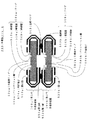
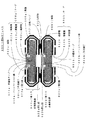
図5は本発明の第1の実施の形態の半導体モジュールについて説明するための断面図である。以下、図5を用いて本発明の第1の実施の形態の半導体モジュールについて説明する。
【0029】
この半導体モジュール500は、第1の半導体装置500a、及び第2の半導体装置500bから構成される。ここで、第2の半導体装置500bは、第1の半導体装置500aと同一の構成であるため、第2の半導体装置500bの説明は、第1の半導体装置500aの説明により省略する。
【0030】
この半導体装置500aは、主表面に複数の外部端子504aを有する集積回路を形成された半導体チップ501aと、導電層510a、およびこの導電層510aを絶縁層509a、513aで挟む構造からなるテープ508aとから構成される。ここで、例えば導電層510aはCu、絶縁層509aはポリイミドやガラスエポキシ、絶縁層513aはソルダーレジストから構成される。
【0031】
また、半導体チップ501aの主表面は、パッシベーション膜505aで覆われている。
【0032】
テープ508aは、半導体チップ501aの主表面から裏面まで延在し、かつ半導体チップ501aの主表面側および裏面側の夫々で半導体チップ501aと固着されている。
【0033】
さらに、導電層510aは、複数の外部端子504aと電気的に接続され、かつ、半導体チップ501aの主表面および裏面の夫々に位置する絶縁層513aに形成された開口部523aおよび533aから露出されている。
【0034】
上述したように本発明の第1の実施の形態の半導体モジュ−ル500は、第1の半導体装置500aの開口部533aから露出する導電層510aが、金属バンプ503を介して、第2の半導体装置500bの開口部523bから露出する導電層510bと接続される。このようにして、第1および第2の半導体装置500a、500bからなる半導体モジュール500が得られる。
【0035】
本発明の第1の実施の形態の半導体モジュ−ル500は、上述のような構造を有するので、テープを有する半導体装置の積み重ね実装を容易に行うことが可能となり、かつ容易に実装できるため、実装工程が簡易なため、コストを下げることも可能となる。
【0036】
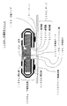
図6は本発明の第2の実施の形態の半導体モジュールについて説明するための断面図である。以下、図6を用いて本発明の第2の実施の形態の半導体モジュールについて説明する。
【0037】
この半導体モジュール600は、本発明の第1の実施の形態の半導体モジュール500とほぼ同様の構成のため、詳しい説明は省略する。本発明の第2の実施の形態の半導体モジュール600の半導体装置600aおよび600bにおいて、テープ608a、およびテープ608bは、夫々緩衝膜607aおよび607b、例えばエラストマーを介して、半導体チップ601a、及び半導体チップ601bと固着されていることを特徴とする。
【0038】
本発明の第2の実施の形態の半導体モジュール600では、本発明の第1の実施の形態の半導体モジュール500と同様の効果を奏することは言うまでもない。さらに、上記のように緩衝膜607aを有するので、これら緩衝膜607a、607bは熱収縮率の差により、半導体チップ601aとテープ608a、半導体チップ601bとテープ608bが夫々剥がれるのを防ぐように働く。したがって、本発明の第1の実施の形態の半導体モジュール500の構造に比して、半導体チップ601aとテープ608a、半導体チップ601bとテープ608b夫々が剥がれにくい構造が得られる。
【0039】
図7は本発明の第3の実施の形態の半導体モジュールについて説明するための断面図である。以下、図7を用いて本発明の第3の実施の形態の半導体モジュ−ルについて説明する。
【0040】
この半導体モジュール700は、本発明の第1の実施の形態の半導体モジュール500とほぼ同様の構成のため、詳しい説明は省略する。本発明の第3の実施の形態の半導体モジュ−ル700の半導体装置700aおよび700bにおいて、導電層710aと外部端子704a、導電層710bと外部端子704bの夫々の接続部が、夫々樹脂702aおよび702bで覆われていることを特徴とする。
【0041】
本発明の第3の実施の形態の半導体モジュール700は、本発明の第1の実施の形態の半導体モジュ−ル500と同様の効果を奏することは言うまでもない。さらに、上記のように導電層710aと外部端子704a、導電層710bと外部端子704bの夫々の接続部が、夫々樹脂702aおよび702bで覆われている。このため、本発明の第1の実施の形態の半導体モジュール500の構造に比して、導電層710aと外部端子704a、導電層710bと外部端子704bが夫々剥がれにくい、堅固な構造を得ることができる。
【0042】
図8は本発明の第4の実施の形態の半導体モジュールについて説明するための断面図である。以下、図8を用いて本発明の第4の実施の形態の半導体モジュ−ルについて説明する。
【0043】
この半導体モジュール800は、本発明の第1の実施の形態の半導体モジュール500とほぼ同様の構成のため、詳しい説明は省略する。本発明の第4の実施の形態の半導体モジュ−ル800の半導体装置800aおよび800bにおいて、導電層810aと外部端子804aとの接続部を樹脂802aが覆い、半導体チップ801aの側面および裏面を樹脂806aが覆い、導電層810bと外部端子804bとの接続部を樹脂802bが覆い、および半導体チップ801bの側面および裏面を樹脂806bが夫々覆うことを特徴とする。
【0044】
本発明の第4の実施の形態の半導体モジュール800は、本発明の第1の実施の形態の半導体モジュ−ル500と同様の効果を奏することは言うまでもない。さらに、上記のように導電層810aと外部端子804aとの接続部を樹脂802aが覆い、半導体チップ801aの側面および裏面を樹脂806aが覆い、導電層810bと外部端子804bとの接続部を樹脂802bが覆い、および半導体チップ801bの側面および裏面を樹脂806bが夫々覆っている。このため、本発明の第1の実施の形態の半導体モジュール500の構造に比して、半導体チップ801aおよび801bの主表面方向からの外力に対してより強い、堅固な構造を得ることができる。
【0045】
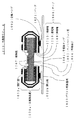
図9は本発明の第5の実施の形態の半導体モジュールについて説明するための断面図である。以下、図9を用いて本発明の第5の実施の形態の半導体モジュ−ルについて説明する。
【0046】
この半導体モジュール900は、半導体装置900aおよびプリント配線基板920から構成される。
【0047】
この半導体装置900aは、主表面に複数の外部端子904を有する集積回路を形成された半導体チップ901と、導電層910、およびこの導電層910を絶縁層909、913で挟む構造からなるテープ908とから構成される。ここで、例えば導電層910はCu、絶縁層909はポリイミドやガラスエポキシ、絶縁層913はソルダーレジストから構成される。
【0048】
また、半導体チップ901の主表面は、パッシベーション膜905で覆われている。
【0049】
テープ908は、半導体チップ901の主表面から裏面まで延在し、かつ半導体チップ901の主表面側および裏面側の夫々で半導体チップ901と固着されている。
【0050】
さらに、導電層910は、複数の外部端子904と電気的に接続され、かつ、半導体チップ901の主表面および裏面の夫々に位置する絶縁層913に形成された開口部903aおよび903bから露出されている。
【0051】
この半導体装置900aの開口部903bで露出する導電層910の表面が、金属バンプ903を用いて、プリント配線基板920上のパッド921と電気的に接続されている。ここで、パッド921は、例えばNi−Auまたは半田から構成されている。
【0052】
上述したように本発明の第5の実施の形態の半導体モジュール900は、導電層910を露出する開口部903aが半導体チップ901の主表面側に設けられている。したがって、半導体装置900aとプリント配線基板920との積み重ね実装を容易にする。さらに、実装に用いられなかった半導体装置の開口部903aから露出する導電層910は、半導体装置900aとプリント配線基板920とが接続されているか否かの電気的テストに用いることができる。
【0053】
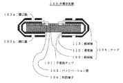
図10は本発明の第6の実施の形態の半導体装置モジュールについて説明するための断面図である。以下、図10を用いて本発明の第6の実施の形態の半導体モジュ−ルについて説明する。
【0054】
この半導体モジュール1000は、本発明の第5の実施の形態の半導体モジュール900とほぼ同様の構成のため、詳しい説明は省略する。本発明の第6の実施の形態の半導体モジュ−ル1000の半導体装置1000aにおいて、テープ1008が緩衝膜1007、例えばエラストマーを介して、半導体チップ1001と固着されていることを特徴とする。
【0055】
本発明の第6の実施の形態の半導体モジュール1000は、本発明の第5の実施の形態の半導体モジュ−ル900と同様の効果を奏することは言うまでもない。さらに、上記のような緩衝膜1007を有するので、この緩衝膜1007は熱収縮率の差により、テープ1008が半導体チップ1001から剥がれるのを防ぐように働く。したがって、本発明の第5の実施の形態の半導体モジュール900の構造に比して、よりテープ1008と半導体チップ1001が剥がれにくい構造が得られる。
【0056】
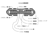
図11は本発明の第7の実施の形態の半導体装置モジュールについて説明するための断面図である。以下、図11を用いて本発明の第7の実施の形態の半導体モジュ−ルについて説明する。
【0057】
この半導体モジュール1100は、本発明の第5の実施の形態の半導体モジュール900aとほぼ同様の構成のため、詳しい説明は省略する。本発明の第7の実施の形態の半導体モジュ−ル1100の半導体装置1100aにおいて、導電層1110と外部端子1104との接続部が樹脂1102で覆われていることを特徴とする。
【0058】
本発明の第7の実施の形態の半導体モジュール1100は、本発明の第5の実施の形態の半導体モジュ−ル900と同様の効果を奏することは言うまでもない。さらに、上記のように導電層1110と外部端子1104との接続部が樹脂1102で覆われている。このため、本発明の第5の実施の形態の半導体モジュール900の構造に比して、外部端子1104と導電層1110が剥がれにくい、堅固な構造を得ることができる。
【0059】
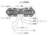
図12は本発明の第8の実施の形態の半導体装置モジュールについて説明するための断面図である。以下、図12を用いて本発明の第8の実施の形態の半導体モジュ−ルについて説明する。
【0060】
この半導体モジュール1200は、本発明の第5の実施の形態の半導体モジュール900とほぼ同様の構成のため、詳しい説明は省略する。本発明の第8の実施の形態の半導体モジュ−ル1200の半導体装置1200aにおいて、導電層1210と外部端子1204との接続部を樹脂1202が覆い、さらには半導体チップ1201の側面および裏面を、樹脂1206が夫々覆うことを特徴とする。
【0061】
本発明の第8の実施の形態の半導体モジュール1200は、本発明の第5の実施の形態の半導体モジュ−ル900と同様の効果を奏することは言うまでもない。さらに、上記のように導電層1210と外部端子1204との接続部を樹脂1202が覆い、さらには半導体チップ1201の側面および裏面を、樹脂1206が夫々覆っている。このため、本発明の第5の実施の形態の半導体モジュール900の構造に比して、半導体チップ1201の主表面方向からの外力に対してより強い、堅固な構造を得ることができる。
【0062】
【発明の効果】
本発明の半導体モジュ−ルは、第1に、半導体装置の主表面側に開口部、裏面側に開口部を有するので、開口部から露出する導電層、もしくは、開口部から露出する導電層、もしくは、これら両方と、外部装置、例えば他の半導体装置と電気的に接続できる。つまり、複数の半導体装置の積み重ね実装を容易にすることができる。第2に、開口部から露出する導電層、もしくは、開口部から露出する導電層の一方が他の半導体装置との接続に用いる場合、他方は半導体装置自身の電気的テストに用いることができる。
【0063】
また、本発明の半導体モジュ−ルにおいて、第1の半導体装置は、開口部から露出する導電層を介して、第2の半導体装置または、プリント配線基板と接続される。したがって、本発明の半導体モジュ−ルは、複数の半導体装置の積み重ね実装を容易に行うことが可能となり、かつ容易に実装できるため、実装工程が簡易なため、コストを下げることも可能となる。
【図面の簡単な説明】
【図1】本発明の第1の実施の形態の半導体装置の構造を断面図で示すものである。
【図2】本発明の第2の実施の形態の半導体装置の構造を断面図で示すものである。
【図3】本発明の第3の実施の形態の半導体装置の構造を断面図で示すものである。
【図4】本発明の第4の実施の形態の半導体装置の構造を断面図で示すものである。
【図5】本発明の第1の実施の形態の半導体モジュールの構造を断面図で示すものである。
【図6】本発明の第2の実施の形態の半導体モジュールの構造を断面図で示すものである。
【図7】本発明の第3の実施の形態の半導体モジュールの構造を断面図で示すものである。
【図8】本発明の第4の実施の形態の半導体モジュールの構造を断面図で示すものである。
【図9】本発明の第5の実施の形態の半導体モジュールの構造を断面図で示すものである。
【図10】本発明の第6の実施の形態の半導体モジュールの構造を断面図で示すものである。
【図11】本発明の第7の実施の形態の半導体モジュールの構造を断面図で示すものである。
【図12】本発明の第8の実施の形態の半導体モジュールの構造を断面図で示すものである。
【図13】従来のμBGA型半導体装置の構造の断面図を示すものである。
【符号の説明】
100:半導体装置
101:半導体チップ
103a:開口部
103b:開口部
104:外部端子
105:パッシベーション膜
108:テープ
109:絶縁層
110:導電層
113:絶縁層[0001]
TECHNICAL FIELD OF THE INVENTION
The present invention relates to a μBGA (μBall Grid Array) type semiconductor device, and more particularly to a stackable μBGA type semiconductor device.
[0002]
[Prior art]
FIG. 13 is a sectional structural view of a conventional μBGA type semiconductor device. As shown in FIG. 13, a conventional μBGA type semiconductor device 1300 includes a semiconductor chip 1301 having an integrated circuit having a plurality of external terminals 1304 formed on a main surface thereof, a conductive layer 1310, and an insulating layer 1309. , And a tape 1308 sandwiched between insulating layers 1313. Here, for example, the conductive layer 1310 is made of Cu, the insulating layer 1309 is made of polyimide or glass epoxy, and the insulating layer 1313 is made of solder resist.
[0003]
The main surface of the semiconductor chip 1301 is covered with a passivation film 1305.
[0004]
Further, the conductive layer 1310 is electrically connected to the plurality of external terminals 1304 and is exposed from an opening 1303a formed in the insulating layer 1313.
[0005]
Further, the tape 1308 is fixed on the passivation film 1305 via a buffer film 1307, for example, an elastomer.
[0006]
The connection between the conductive layer 1310 and the external terminal 1304 is covered with a resin 1302.
[0007]
[Problems to be solved by the invention]
However, in the conventional μBGA type semiconductor device, a connection portion electrically connectable to an external device, for example, another semiconductor device, that is, the conductive layer 1310 exposed from the opening 1303 a is formed only on the main surface of the semiconductor chip 1301. Due to the structure, it has been difficult to stack and mount a plurality of semiconductor devices.
[0008]
SUMMARY OF THE INVENTION An object of the present invention is to provide a semiconductor device and a semiconductor module which facilitate stacking and mounting of a plurality of semiconductor devices.
[0009]
[Means for Solving the Problems]
Therefore, a semiconductor device of the present invention includes a semiconductor chip on which an integrated circuit having a plurality of external terminals is formed on a main surface, a semiconductor chip extending from the main surface of the semiconductor chip to the back surface of the semiconductor chip, and Each of the back surfaces has a tape fixed to the semiconductor chip. The tape includes a conductive layer and an insulating layer sandwiching the conductive layer, and the conductive layer and a plurality of external terminals are electrically connected to each other. The semiconductor device is characterized in that the semiconductor chip has openings that expose the conductive layer in the insulating layer located on each of the main surface and the back surface of the semiconductor chip.
[0010]
Further, the semiconductor module of the present invention includes a semiconductor chip having an integrated circuit having a plurality of external terminals formed on a main surface, a semiconductor chip extending from the main surface of the semiconductor chip to the back surface of the semiconductor chip, and And a tape fixed to the semiconductor chip on each of the back surface side. The tape includes a conductive layer, an insulating layer sandwiching the conductive layer, and the conductive layer and a plurality of external terminals. A first semiconductor device that is electrically connected and has an opening exposing a conductive layer in an insulating layer located on each of a main surface and a back surface of a semiconductor chip; And a second semiconductor device having a pad that is electrically connected.
[0011]
BEST MODE FOR CARRYING OUT THE INVENTION
FIG. 1 is a sectional view for explaining a semiconductor device according to a first embodiment of the present invention. Hereinafter, a semiconductor device according to a first embodiment of the present invention will be described with reference to FIG.
[0012]
The semiconductor device 100 includes a semiconductor chip 101 on which an integrated circuit having a plurality of external terminals 104 is formed on a main surface, a
[0013]
The main surface of the semiconductor chip 101 is covered with a passivation film 105.
[0014]
The tape 108 extends from the main surface to the back surface of the semiconductor chip 101, and is fixed to the semiconductor chip 101 on each of the main surface side and the back surface side of the semiconductor chip 101.
[0015]
Further, the
[0016]
As described above, in the semiconductor device 100 according to the first embodiment of the present invention, first, since the semiconductor device 100 has the opening 103a on the main surface side and the opening 103b on the back surface, the semiconductor device 100 is exposed from the opening 103a. The
[0017]
In the semiconductor device according to the first embodiment of the present invention, the
[0018]
Further, a flexible tape may be used instead of the tape 108.
[0019]
FIG. 2 is a cross-sectional view for explaining a semiconductor device according to a second embodiment of the present invention. Hereinafter, a semiconductor device according to a second embodiment of the present invention will be described with reference to FIG.
[0020]
The semiconductor device 200 has substantially the same configuration as the semiconductor device 100 according to the first embodiment of the present invention, and thus a detailed description is omitted. The present embodiment is characterized in that, in the semiconductor device 100 according to the first embodiment of the present invention, the tape 108 is fixed to the semiconductor chip 101 via a buffer film 207, for example, an elastomer.
[0021]
It goes without saying that the semiconductor device 200 according to the second embodiment of the present invention has the same effect as the semiconductor device 100 according to the first embodiment of the present invention. Further, as described above, the tape 108 is fixed to the semiconductor chip 101 via the buffer film 207. The buffer film 207 functions to prevent the tape 108 from peeling off from the semiconductor chip 101 due to the difference in the heat shrinkage. Therefore, compared to the structure of the semiconductor device 100 according to the first embodiment of the present invention, a structure is obtained in which the tape 108 and the semiconductor chip 101 are less likely to peel off.
[0022]
FIG. 3 is a cross-sectional view for explaining a semiconductor device according to a third embodiment of the present invention. Hereinafter, a semiconductor device according to a third embodiment of the present invention will be described with reference to FIG.
[0023]
The semiconductor device 300 has substantially the same configuration as the semiconductor device 100 according to the first embodiment of the present invention, and a detailed description thereof will be omitted. This embodiment is characterized in that, in the semiconductor device 100 according to the first embodiment of the present invention, a connection portion between the
[0024]
It goes without saying that the semiconductor device 300 according to the third embodiment of the present invention has the same effect as the semiconductor device 100 according to the first embodiment of the present invention. Further, the connection between the
[0025]
FIG. 4 is a cross-sectional view illustrating a semiconductor device according to a fourth embodiment of the present invention. Hereinafter, a semiconductor device according to a fourth embodiment of the present invention will be described with reference to FIG.
[0026]
The semiconductor device 400 has substantially the same configuration as the semiconductor device 100 according to the first embodiment of the present invention, and a detailed description thereof will be omitted. In the present embodiment, in the semiconductor device 100 according to the first embodiment of the present invention, the resin 302 covers a connection portion between the
[0027]
It goes without saying that the semiconductor device 400 according to the fourth embodiment of the present invention has the same effect as the semiconductor device 100 according to the first embodiment of the present invention. Further, as described above, the connection between the
[0028]
FIG. 5 is a cross-sectional view for explaining the semiconductor module according to the first embodiment of the present invention. Hereinafter, the semiconductor module according to the first embodiment of the present invention will be described with reference to FIG.
[0029]
This semiconductor module 500 includes a first semiconductor device 500a and a second semiconductor device 500b. Here, since the second semiconductor device 500b has the same configuration as the first semiconductor device 500a, the description of the second semiconductor device 500b will be omitted by the description of the first semiconductor device 500a.
[0030]
The semiconductor device 500a includes a semiconductor chip 501a on which an integrated circuit having a plurality of external terminals 504a is formed on a main surface, a conductive layer 510a, and a tape 508a having a structure in which the conductive layer 510a is sandwiched between insulating layers 509a and 513a. Consists of Here, for example, the conductive layer 510a is made of Cu, the insulating layer 509a is made of polyimide or glass epoxy, and the insulating layer 513a is made of solder resist.
[0031]
The main surface of the semiconductor chip 501a is covered with a passivation film 505a.
[0032]
The tape 508a extends from the main surface to the back surface of the semiconductor chip 501a, and is fixed to the semiconductor chip 501a on each of the main surface side and the back surface side of the semiconductor chip 501a.
[0033]
Further, conductive layer 510a is electrically connected to a plurality of external terminals 504a, and is exposed from openings 523a and 533a formed in insulating layer 513a located on the main surface and the back surface of semiconductor chip 501a, respectively. I have.
[0034]
As described above, in the semiconductor module 500 according to the first embodiment of the present invention, the conductive layer 510a exposed from the opening 533a of the first semiconductor device 500a has the second semiconductor It is connected to the conductive layer 510b exposed from the opening 523b of the device 500b. Thus, the semiconductor module 500 including the first and second semiconductor devices 500a and 500b is obtained.
[0035]
Since the semiconductor module 500 according to the first embodiment of the present invention has the above-described structure, the semiconductor devices having tapes can be easily stacked and mounted, and can be easily mounted. Since the mounting process is simple, the cost can be reduced.
[0036]
FIG. 6 is a cross-sectional view for describing a semiconductor module according to a second embodiment of the present invention. Hereinafter, a semiconductor module according to a second embodiment of the present invention will be described with reference to FIG.
[0037]
The semiconductor module 600 has substantially the same configuration as the semiconductor module 500 according to the first embodiment of the present invention, and thus a detailed description is omitted. In the
[0038]
It goes without saying that the semiconductor module 600 according to the second embodiment of the present invention has the same effect as the semiconductor module 500 according to the first embodiment of the present invention. Further, since the buffer films 607a and 607b have the above-described buffer films 607a and 607b, they function to prevent the semiconductor chip 601a and the tape 608a and the semiconductor chip 601b and the tape 608b from being peeled off due to a difference in thermal contraction rate. Therefore, as compared with the structure of the semiconductor module 500 according to the first embodiment of the present invention, a structure is obtained in which the semiconductor chip 601a and the tape 608a and the semiconductor chip 601b and the tape 608b are less likely to peel off.
[0039]
FIG. 7 is a sectional view illustrating a semiconductor module according to a third embodiment of the present invention. Hereinafter, a semiconductor module according to a third embodiment of the present invention will be described with reference to FIG.
[0040]
The
[0041]
It goes without saying that the
[0042]
FIG. 8 is a sectional view for describing a semiconductor module according to a fourth embodiment of the present invention. Hereinafter, a semiconductor module according to a fourth embodiment of the present invention will be described with reference to FIG.
[0043]
The semiconductor module 800 has substantially the same configuration as the semiconductor module 500 according to the first embodiment of the present invention, and thus a detailed description is omitted. In the semiconductor devices 800a and 800b of the semiconductor module 800 according to the fourth embodiment of the present invention, the resin 802a covers the connection between the conductive layer 810a and the external terminal 804a, and the resin 806a covers the side and the back of the semiconductor chip 801a. , A connection portion between the conductive layer 810b and the
[0044]
It goes without saying that the semiconductor module 800 according to the fourth embodiment of the present invention has the same effect as the semiconductor module 500 according to the first embodiment of the present invention. Further, as described above, the connection between the conductive layer 810a and the external terminal 804a is covered with the resin 802a, the side surface and the back surface of the semiconductor chip 801a are covered with the resin 806a, and the connection between the conductive layer 810b and the
[0045]
FIG. 9 is a sectional view illustrating a semiconductor module according to a fifth embodiment of the present invention. Hereinafter, a semiconductor module according to a fifth embodiment of the present invention will be described with reference to FIG.
[0046]
The semiconductor module 900 includes a semiconductor device 900a and a printed wiring board 920.
[0047]
This semiconductor device 900a includes a semiconductor chip 901 formed with an integrated circuit having a plurality of external terminals 904 on a main surface, a conductive layer 910, and a tape 908 having a structure in which the conductive layer 910 is sandwiched between insulating layers 909 and 913. Consists of Here, for example, the conductive layer 910 is made of Cu, the insulating layer 909 is made of polyimide or glass epoxy, and the insulating layer 913 is made of solder resist.
[0048]
The main surface of the semiconductor chip 901 is covered with a
[0049]
The tape 908 extends from the main surface to the back surface of the semiconductor chip 901, and is fixed to the semiconductor chip 901 on each of the main surface side and the back surface side of the semiconductor chip 901.
[0050]
Further, conductive layer 910 is electrically connected to a plurality of external terminals 904, and is exposed from openings 903 a and 903 b formed in insulating layer 913 located on the main surface and the back surface of semiconductor chip 901, respectively. I have.
[0051]
The surface of the conductive layer 910 exposed at the opening 903b of the semiconductor device 900a is electrically connected to the pad 921 on the printed wiring board 920 using the metal bump 903. Here, the pad 921 is made of, for example, Ni-Au or solder.
[0052]
As described above, in the semiconductor module 900 according to the fifth embodiment of the present invention, the opening 903a exposing the conductive layer 910 is provided on the main surface side of the semiconductor chip 901. Therefore, the stacked mounting of the semiconductor device 900a and the printed wiring board 920 is facilitated. Further, the conductive layer 910 exposed from the opening 903a of the semiconductor device which has not been used for mounting can be used for an electrical test of whether or not the semiconductor device 900a and the printed wiring board 920 are connected.
[0053]
FIG. 10 is a sectional view illustrating a semiconductor device module according to a sixth embodiment of the present invention. Hereinafter, a semiconductor module according to a sixth embodiment of the present invention will be described with reference to FIG.
[0054]
This semiconductor module 1000 has substantially the same configuration as the semiconductor module 900 according to the fifth embodiment of the present invention, and therefore detailed description is omitted. The semiconductor device 1000a of the semiconductor module 1000 according to the sixth embodiment of the present invention is characterized in that a tape 1008 is fixed to a semiconductor chip 1001 via a buffer film 1007, for example, an elastomer.
[0055]
Needless to say, the semiconductor module 1000 according to the sixth embodiment of the present invention has the same effect as the semiconductor module 900 according to the fifth embodiment of the present invention. Further, since the buffer film 1007 has the above-described buffer film 1007, the buffer film 1007 functions to prevent the tape 1008 from being peeled off from the semiconductor chip 1001 due to a difference in heat shrinkage. Therefore, compared to the structure of the semiconductor module 900 according to the fifth embodiment of the present invention, a structure in which the tape 1008 and the semiconductor chip 1001 are less likely to peel off is obtained.
[0056]
FIG. 11 is a sectional view for explaining a semiconductor device module according to a seventh embodiment of the present invention. Hereinafter, a semiconductor module according to a seventh embodiment of the present invention will be described with reference to FIG.
[0057]
This semiconductor module 1100 has substantially the same configuration as the semiconductor module 900a according to the fifth embodiment of the present invention, and thus detailed description is omitted. The semiconductor device 1100a of the semiconductor module 1100 according to the seventh embodiment of the present invention is characterized in that the connection between the conductive layer 1110 and the external terminal 1104 is covered with a
[0058]
It goes without saying that the semiconductor module 1100 according to the seventh embodiment of the present invention has the same effect as the semiconductor module 900 according to the fifth embodiment of the present invention. Further, the connection portion between the conductive layer 1110 and the external terminal 1104 is covered with the
[0059]
FIG. 12 is a cross-sectional view for describing a semiconductor device module according to an eighth embodiment of the present invention. Hereinafter, a semiconductor module according to an eighth embodiment of the present invention will be described with reference to FIG.
[0060]
The configuration of the semiconductor module 1200 is substantially the same as that of the semiconductor module 900 according to the fifth embodiment of the present invention, and a detailed description thereof will be omitted. In the semiconductor device 1200a of the semiconductor module 1200 according to the eighth embodiment of the present invention, the connection between the conductive layer 1210 and the external terminal 1204 is covered with the
[0061]
It goes without saying that the semiconductor module 1200 according to the eighth embodiment of the present invention has the same effect as the semiconductor module 900 according to the fifth embodiment of the present invention. Further, as described above, the connection between the conductive layer 1210 and the external terminal 1204 is covered with the
[0062]
【The invention's effect】
Since the semiconductor module of the present invention has an opening on the main surface side and an opening on the back side of the semiconductor device, the conductive layer exposed from the opening, or the conductive layer exposed from the opening, Alternatively, both of them can be electrically connected to an external device, for example, another semiconductor device. That is, stacking and mounting of a plurality of semiconductor devices can be facilitated. Second, when one of the conductive layer exposed from the opening and the conductive layer exposed from the opening is used for connection to another semiconductor device, the other can be used for an electrical test of the semiconductor device itself.
[0063]
In the semiconductor module according to the present invention, the first semiconductor device is connected to the second semiconductor device or the printed wiring board via the conductive layer exposed from the opening. Therefore, the semiconductor module according to the present invention can easily stack and mount a plurality of semiconductor devices, and can easily mount the semiconductor module, so that the mounting process is simple and the cost can be reduced.
[Brief description of the drawings]
FIG. 1 is a sectional view showing a structure of a semiconductor device according to a first embodiment of the present invention.
FIG. 2 is a sectional view showing a structure of a semiconductor device according to a second embodiment of the present invention;
FIG. 3 is a sectional view showing a structure of a semiconductor device according to a third embodiment of the present invention;
FIG. 4 is a sectional view showing a structure of a semiconductor device according to a fourth embodiment of the present invention;
FIG. 5 is a sectional view showing the structure of the semiconductor module according to the first embodiment of the present invention.
FIG. 6 is a sectional view showing a structure of a semiconductor module according to a second embodiment of the present invention.
FIG. 7 is a sectional view showing a structure of a semiconductor module according to a third embodiment of the present invention.
FIG. 8 is a sectional view showing a structure of a semiconductor module according to a fourth embodiment of the present invention.
FIG. 9 is a sectional view showing a structure of a semiconductor module according to a fifth embodiment of the present invention.
FIG. 10 is a sectional view showing a structure of a semiconductor module according to a sixth embodiment of the present invention.
FIG. 11 is a sectional view showing a structure of a semiconductor module according to a seventh embodiment of the present invention.
FIG. 12 is a sectional view showing a structure of a semiconductor module according to an eighth embodiment of the present invention.
FIG. 13 is a sectional view showing the structure of a conventional μBGA type semiconductor device.
[Explanation of symbols]
100: semiconductor device 101: semiconductor chip 103a: opening 103b: opening 104: external terminal 105: passivation film 108: tape 109: insulating layer 110: conductive layer 113: insulating layer
Claims (12)
前記半導体チップの前記主表面から前記半導体チップの裏面まで延在し、かつ前記半導体チップの前記主表面側及び前記裏面側の夫々で前記半導体チップと固着されるテ−プとを有し、
前記テ−プは、導電層と、この導電層を挟む絶縁層とからなり、かつ前記導電層と前記複数の外部端子とが電気的に接続され、かつ前記半導体チップの前記主表面及び前記裏面の夫々に位置する前記絶縁層に前記導電層を露出する開口部を夫々に有し、かつ前記テープと前記半導体チップの側面との間には空隙部が設けられていることを特徴とする半導体装置。A semiconductor chip on which an integrated circuit having a plurality of external terminals is formed on a main surface;
A tape extending from the main surface of the semiconductor chip to the back surface of the semiconductor chip, and being fixed to the semiconductor chip on each of the main surface side and the back surface side of the semiconductor chip;
The tape comprises a conductive layer and an insulating layer sandwiching the conductive layer, the conductive layer and the plurality of external terminals are electrically connected, and the main surface and the back surface of the semiconductor chip are provided. semiconductors between an opening exposing said conductive layer on said insulating layer located respectively possess respectively, and with the tape and the side surface of the semiconductor chip, characterized in that the air gap is provided apparatus.
前記開口部で露出する前記導電層表面と電気的に接続されている第2の半導体装置とを有することを特徴とする半導体モジュール。A semiconductor chip on which an integrated circuit having a plurality of external terminals is formed on a main surface, extending from the main surface of the semiconductor chip to a back surface of the semiconductor chip, and the main surface side and the back surface side of the semiconductor chip; Each of which has a tape fixed to the semiconductor chip, the tape includes a conductive layer and an insulating layer sandwiching the conductive layer, and the tape includes the conductive layer and the plurality of external terminals. There are electrically connected, and said main surface and said opening exposing said conductive layer on the insulating layer possess respectively a, and a side surface of the tape and the semiconductor chip located on each of the back surface of the semiconductor chip A first semiconductor device having a gap between the first semiconductor device and
And a second semiconductor device electrically connected to the conductive layer surface exposed at the opening.
前記第1の半導体装置と電気的に接続されているプリント配線基板とを備えたことを特徴とする半導体モジュール。A semiconductor chip on which an integrated circuit having a plurality of external terminals is formed on a main surface, extending from the main surface of the semiconductor chip to a back surface of the semiconductor chip, and the main surface side and the back surface side of the semiconductor chip; Each of which has a tape fixed to the semiconductor chip, the tape includes a conductive layer and an insulating layer sandwiching the conductive layer, and the tape includes the conductive layer and the plurality of external terminals. There are electrically connected, and the semiconductor chip said main surface and have a opening exposing said conductive layer on said insulating layer positioned on each of the back side of, and the side surface of the tape and the semiconductor chip A first semiconductor device having a gap between the first semiconductor device;
A semiconductor module, comprising: a printed wiring board electrically connected to the first semiconductor device.
Priority Applications (2)
| Application Number | Priority Date | Filing Date | Title |
|---|---|---|---|
| JP11744299A JP3602000B2 (en) | 1999-04-26 | 1999-04-26 | Semiconductor device and semiconductor module |
| US09/536,763 US6329708B1 (en) | 1999-04-26 | 2000-03-28 | Micro ball grid array semiconductor device and semiconductor module |
Applications Claiming Priority (1)
| Application Number | Priority Date | Filing Date | Title |
|---|---|---|---|
| JP11744299A JP3602000B2 (en) | 1999-04-26 | 1999-04-26 | Semiconductor device and semiconductor module |
Related Child Applications (5)
| Application Number | Title | Priority Date | Filing Date |
|---|---|---|---|
| JP2003132848A Division JP3859617B2 (en) | 2003-05-12 | 2003-05-12 | Semiconductor device |
| JP2003132849A Division JP3859618B2 (en) | 2003-05-12 | 2003-05-12 | Semiconductor device |
| JP2003132851A Division JP3893363B2 (en) | 2003-05-12 | 2003-05-12 | Semiconductor module |
| JP2003132852A Division JP3836811B2 (en) | 2003-05-12 | 2003-05-12 | Semiconductor module |
| JP2003132850A Division JP2003309220A (en) | 2003-05-12 | 2003-05-12 | Semiconductor device |
Publications (2)
| Publication Number | Publication Date |
|---|---|
| JP2000307029A JP2000307029A (en) | 2000-11-02 |
| JP3602000B2 true JP3602000B2 (en) | 2004-12-15 |
Family
ID=14711761
Family Applications (1)
| Application Number | Title | Priority Date | Filing Date |
|---|---|---|---|
| JP11744299A Expired - Fee Related JP3602000B2 (en) | 1999-04-26 | 1999-04-26 | Semiconductor device and semiconductor module |
Country Status (2)
| Country | Link |
|---|---|
| US (1) | US6329708B1 (en) |
| JP (1) | JP3602000B2 (en) |
Cited By (1)
| Publication number | Priority date | Publication date | Assignee | Title |
|---|---|---|---|---|
| US7656678B2 (en) | 2001-10-26 | 2010-02-02 | Entorian Technologies, Lp | Stacked module systems |
Families Citing this family (43)
| Publication number | Priority date | Publication date | Assignee | Title |
|---|---|---|---|---|
| IL123207A0 (en) | 1998-02-06 | 1998-09-24 | Shellcase Ltd | Integrated circuit device |
| US6323060B1 (en) | 1999-05-05 | 2001-11-27 | Dense-Pac Microsystems, Inc. | Stackable flex circuit IC package and method of making same |
| US6262895B1 (en) | 2000-01-13 | 2001-07-17 | John A. Forthun | Stackable chip package with flex carrier |
| JP2001223323A (en) * | 2000-02-10 | 2001-08-17 | Mitsubishi Electric Corp | Semiconductor device |
| US6562641B1 (en) * | 2000-08-22 | 2003-05-13 | Micron Technology, Inc. | Apparatus and methods of semiconductor packages having circuit-bearing interconnect components |
| KR100855015B1 (en) * | 2000-12-21 | 2008-08-28 | 테쎄라 테크놀로지스 헝가리 케이에프티. | Packaged integrated circuit and manufacturing method thereof |
| DE10120408B4 (en) * | 2001-04-25 | 2006-02-02 | Infineon Technologies Ag | Electronic component with a semiconductor chip, electronic assembly of stacked semiconductor chips and method for their production |
| CN1185915C (en) * | 2001-06-13 | 2005-01-19 | 佳能株式会社 | Flexible substrate, semiconductor device, camera device and X-ray camera system |
| US7026708B2 (en) | 2001-10-26 | 2006-04-11 | Staktek Group L.P. | Low profile chip scale stacking system and method |
| US20030234443A1 (en) * | 2001-10-26 | 2003-12-25 | Staktek Group, L.P. | Low profile stacking system and method |
| US20060255446A1 (en) | 2001-10-26 | 2006-11-16 | Staktek Group, L.P. | Stacked modules and method |
| US7053478B2 (en) | 2001-10-26 | 2006-05-30 | Staktek Group L.P. | Pitch change and chip scale stacking system |
| US7202555B2 (en) * | 2001-10-26 | 2007-04-10 | Staktek Group L.P. | Pitch change and chip scale stacking system and method |
| US6914324B2 (en) | 2001-10-26 | 2005-07-05 | Staktek Group L.P. | Memory expansion and chip scale stacking system and method |
| US6956284B2 (en) | 2001-10-26 | 2005-10-18 | Staktek Group L.P. | Integrated circuit stacking system and method |
| US7485951B2 (en) | 2001-10-26 | 2009-02-03 | Entorian Technologies, Lp | Modularized die stacking system and method |
| US7310458B2 (en) | 2001-10-26 | 2007-12-18 | Staktek Group L.P. | Stacked module systems and methods |
| US7371609B2 (en) | 2001-10-26 | 2008-05-13 | Staktek Group L.P. | Stacked module systems and methods |
| US6940729B2 (en) | 2001-10-26 | 2005-09-06 | Staktek Group L.P. | Integrated circuit stacking system and method |
| US7081373B2 (en) | 2001-12-14 | 2006-07-25 | Staktek Group, L.P. | CSP chip stack with flex circuit |
| US6835592B2 (en) * | 2002-05-24 | 2004-12-28 | Micron Technology, Inc. | Methods for molding a semiconductor die package with enhanced thermal conductivity |
| DE10238581B4 (en) * | 2002-08-22 | 2008-11-27 | Qimonda Ag | Semiconductor component |
| JP4081666B2 (en) * | 2002-09-24 | 2008-04-30 | セイコーエプソン株式会社 | Semiconductor device and manufacturing method thereof, circuit board, and electronic apparatus |
| WO2004055891A1 (en) * | 2002-12-17 | 2004-07-01 | Fujitsu Limited | Semiconductor device and stacked semiconductor device |
| US7542304B2 (en) | 2003-09-15 | 2009-06-02 | Entorian Technologies, Lp | Memory expansion and integrated circuit stacking system and method |
| SG120123A1 (en) * | 2003-09-30 | 2006-03-28 | Micron Technology Inc | Castellated chip-scale packages and methods for fabricating the same |
| US20060261458A1 (en) * | 2003-11-12 | 2006-11-23 | Amkor Technology, Inc. | Semiconductor package and manufacturing method thereof |
| US7309914B2 (en) | 2005-01-20 | 2007-12-18 | Staktek Group L.P. | Inverted CSP stacking system and method |
| US7033861B1 (en) | 2005-05-18 | 2006-04-25 | Staktek Group L.P. | Stacked module systems and method |
| US7566853B2 (en) * | 2005-08-12 | 2009-07-28 | Tessera, Inc. | Image sensor employing a plurality of photodetector arrays and/or rear-illuminated architecture |
| US7576995B2 (en) | 2005-11-04 | 2009-08-18 | Entorian Technologies, Lp | Flex circuit apparatus and method for adding capacitance while conserving circuit board surface area |
| US7605454B2 (en) | 2006-01-11 | 2009-10-20 | Entorian Technologies, Lp | Memory card and method for devising |
| US7508058B2 (en) | 2006-01-11 | 2009-03-24 | Entorian Technologies, Lp | Stacked integrated circuit module |
| US7508069B2 (en) | 2006-01-11 | 2009-03-24 | Entorian Technologies, Lp | Managed memory component |
| US7608920B2 (en) | 2006-01-11 | 2009-10-27 | Entorian Technologies, Lp | Memory card and method for devising |
| US7304382B2 (en) | 2006-01-11 | 2007-12-04 | Staktek Group L.P. | Managed memory component |
| US7468553B2 (en) | 2006-10-20 | 2008-12-23 | Entorian Technologies, Lp | Stackable micropackages and stacked modules |
| US7807508B2 (en) * | 2006-10-31 | 2010-10-05 | Tessera Technologies Hungary Kft. | Wafer-level fabrication of lidded chips with electrodeposited dielectric coating |
| US7417310B2 (en) | 2006-11-02 | 2008-08-26 | Entorian Technologies, Lp | Circuit module having force resistant construction |
| JP5012612B2 (en) * | 2008-03-26 | 2012-08-29 | 日本電気株式会社 | Semiconductor device mounting structure and electronic device using the mounting structure |
| EP2291858B1 (en) * | 2008-06-26 | 2012-03-28 | Nxp B.V. | Packaged semiconductor product and method for manufacture thereof |
| EP2390909A1 (en) * | 2010-05-24 | 2011-11-30 | Jerry Hu | Miniature packaging for discrete circuit components |
| US8310040B2 (en) | 2010-12-08 | 2012-11-13 | General Electric Company | Semiconductor device package having high breakdown voltage and low parasitic inductance and method of manufacturing thereof |
Family Cites Families (5)
| Publication number | Priority date | Publication date | Assignee | Title |
|---|---|---|---|---|
| US5583375A (en) * | 1990-06-11 | 1996-12-10 | Hitachi, Ltd. | Semiconductor device with lead structure within the planar area of the device |
| JP2570628B2 (en) * | 1994-09-21 | 1997-01-08 | 日本電気株式会社 | Semiconductor package and manufacturing method thereof |
| US6002167A (en) * | 1995-09-22 | 1999-12-14 | Hitachi Cable, Ltd. | Semiconductor device having lead on chip structure |
| JP3011233B2 (en) * | 1997-05-02 | 2000-02-21 | 日本電気株式会社 | Semiconductor package and its semiconductor mounting structure |
| US6028365A (en) * | 1998-03-30 | 2000-02-22 | Micron Technology, Inc. | Integrated circuit package and method of fabrication |
-
1999
- 1999-04-26 JP JP11744299A patent/JP3602000B2/en not_active Expired - Fee Related
-
2000
- 2000-03-28 US US09/536,763 patent/US6329708B1/en not_active Expired - Fee Related
Cited By (1)
| Publication number | Priority date | Publication date | Assignee | Title |
|---|---|---|---|---|
| US7656678B2 (en) | 2001-10-26 | 2010-02-02 | Entorian Technologies, Lp | Stacked module systems |
Also Published As
| Publication number | Publication date |
|---|---|
| JP2000307029A (en) | 2000-11-02 |
| US6329708B1 (en) | 2001-12-11 |
Similar Documents
| Publication | Publication Date | Title |
|---|---|---|
| JP3602000B2 (en) | Semiconductor device and semiconductor module | |
| JP3893363B2 (en) | Semiconductor module | |
| US6812573B2 (en) | Semiconductor device and method for manufacturing the same | |
| US5182632A (en) | High density multichip package with interconnect structure and heatsink | |
| JP3410396B2 (en) | High performance integrated circuit chip package | |
| US4941033A (en) | Semiconductor integrated circuit device | |
| US6613606B1 (en) | Structure of high performance combo chip and processing method | |
| US6407448B2 (en) | Stackable ball grid array semiconductor package and fabrication method thereof | |
| US6921980B2 (en) | Integrated semiconductor circuit including electronic component connected between different component connection portions | |
| US6458627B1 (en) | Semiconductor chip package and method of fabricating same | |
| KR20010022384A (en) | Conductive epoxy flip-chip on chip | |
| JPH07503579A (en) | Back ground of flip chip integrated circuit | |
| US6137162A (en) | Chip stack package | |
| JP3859618B2 (en) | Semiconductor device | |
| TWI893151B (en) | Semiconductor package | |
| JP3836811B2 (en) | Semiconductor module | |
| US4933810A (en) | Integrated circuit interconnector | |
| JP3823636B2 (en) | Semiconductor chip module and manufacturing method thereof | |
| US5422515A (en) | Semiconductor module including wiring structures each having different current capacity | |
| JP3859617B2 (en) | Semiconductor device | |
| KR100251868B1 (en) | Chip scale semiconductor package using flexible circuit board and manufacturing method thereof | |
| US20050001327A1 (en) | Semiconductor device, method for manufacturing the same, circuit substrate and electronic device | |
| JP2001007252A (en) | Semiconductor device and method of manufacturing the same | |
| JP4364221B2 (en) | Semiconductor device | |
| JP2003309220A (en) | Semiconductor device |
Legal Events
| Date | Code | Title | Description |
|---|---|---|---|
| A02 | Decision of refusal |
Free format text: JAPANESE INTERMEDIATE CODE: A02 Effective date: 20030610 |
|
| A61 | First payment of annual fees (during grant procedure) |
Free format text: JAPANESE INTERMEDIATE CODE: A61 Effective date: 20040921 |
|
| R150 | Certificate of patent or registration of utility model |
Free format text: JAPANESE INTERMEDIATE CODE: R150 |
|
| FPAY | Renewal fee payment (event date is renewal date of database) |
Free format text: PAYMENT UNTIL: 20081001 Year of fee payment: 4 |
|
| FPAY | Renewal fee payment (event date is renewal date of database) |
Free format text: PAYMENT UNTIL: 20081001 Year of fee payment: 4 |
|
| FPAY | Renewal fee payment (event date is renewal date of database) |
Free format text: PAYMENT UNTIL: 20091001 Year of fee payment: 5 |
|
| S111 | Request for change of ownership or part of ownership |
Free format text: JAPANESE INTERMEDIATE CODE: R313111 |
|
| S531 | Written request for registration of change of domicile |
Free format text: JAPANESE INTERMEDIATE CODE: R313531 |
|
| FPAY | Renewal fee payment (event date is renewal date of database) |
Free format text: PAYMENT UNTIL: 20091001 Year of fee payment: 5 |
|
| R350 | Written notification of registration of transfer |
Free format text: JAPANESE INTERMEDIATE CODE: R350 |
|
| FPAY | Renewal fee payment (event date is renewal date of database) |
Free format text: PAYMENT UNTIL: 20091001 Year of fee payment: 5 |
|
| FPAY | Renewal fee payment (event date is renewal date of database) |
Free format text: PAYMENT UNTIL: 20101001 Year of fee payment: 6 |
|
| FPAY | Renewal fee payment (event date is renewal date of database) |
Free format text: PAYMENT UNTIL: 20101001 Year of fee payment: 6 |
|
| FPAY | Renewal fee payment (event date is renewal date of database) |
Free format text: PAYMENT UNTIL: 20111001 Year of fee payment: 7 |
|
| FPAY | Renewal fee payment (event date is renewal date of database) |
Free format text: PAYMENT UNTIL: 20121001 Year of fee payment: 8 |
|
| FPAY | Renewal fee payment (event date is renewal date of database) |
Free format text: PAYMENT UNTIL: 20121001 Year of fee payment: 8 |
|
| S533 | Written request for registration of change of name |
Free format text: JAPANESE INTERMEDIATE CODE: R313533 |
|
| FPAY | Renewal fee payment (event date is renewal date of database) |
Free format text: PAYMENT UNTIL: 20121001 Year of fee payment: 8 |
|
| R350 | Written notification of registration of transfer |
Free format text: JAPANESE INTERMEDIATE CODE: R350 |
|
| FPAY | Renewal fee payment (event date is renewal date of database) |
Free format text: PAYMENT UNTIL: 20131001 Year of fee payment: 9 |
|
| S531 | Written request for registration of change of domicile |
Free format text: JAPANESE INTERMEDIATE CODE: R313531 |
|
| LAPS | Cancellation because of no payment of annual fees | ||
| R350 | Written notification of registration of transfer |
Free format text: JAPANESE INTERMEDIATE CODE: R350 |