JP3601435B2 - Vehicle driving force control device and vehicle driving force control method - Google Patents
Vehicle driving force control device and vehicle driving force control method Download PDFInfo
- Publication number
- JP3601435B2 JP3601435B2 JP2000321716A JP2000321716A JP3601435B2 JP 3601435 B2 JP3601435 B2 JP 3601435B2 JP 2000321716 A JP2000321716 A JP 2000321716A JP 2000321716 A JP2000321716 A JP 2000321716A JP 3601435 B2 JP3601435 B2 JP 3601435B2
- Authority
- JP
- Japan
- Prior art keywords
- vehicle
- recommended
- speed
- gear ratio
- automatic transmission
- Prior art date
- Legal status (The legal status is an assumption and is not a legal conclusion. Google has not performed a legal analysis and makes no representation as to the accuracy of the status listed.)
- Expired - Fee Related
Links
Images


Description
【0001】
【発明の属する技術分野】
本発明は、車両駆動力制御装置及び車両駆動力制御方法に関するものである。
【0002】
【従来の技術】
従来、自動変速機を搭載した車両においては、エンジンを駆動することによって発生させられた回転を、変速機構に伝達し、該変速機構において変速を行い、変速が行われた後の回転を駆動輪に伝達して車両を走行させるようにしている。
【0003】
前記自動変速機には、有段変速機及び無段変速機が有り、前記有段変速機においては、プラネタリギヤユニットに回転を入力するための歯車要素、プラネタリギヤユニットから回転を出力させるための歯車要素等の組合せを変更することによって変速機構の変速比を有段で変化させ、前記無段変速機においては、プライマリプーリとセカンダリプーリとの間にベルトが張設され、プライマリプーリ及びセカンダリプーリの半径方向におけるベルトの位置、すなわち、有効径を変化させることによって、変速機構の変速比を無段で変化させるようにしている。そのために、プライマリプーリ及びセカンダリプーリはそれぞれ固定シーブ及び可動シーブを備え、該各可動シーブを油圧サーボ、又は電動機等の駆動手段によって移動させることにより、前記有効径を変化させるようになっている。
【0004】
ところで、ナビゲーション装置によって取得された道路情報に基づいて車両の駆動力の制御、すなわち、駆動力制御を行うようにした車両駆動力制御装置が提供されている。該車両駆動力制御装置は、前記ナビゲーション装置の制御を行うナビゲーション処理部、及び自動変速機の制御を行う自動変速機制御部を備える。そして、駆動力制御として、例えば、車両がコーナに近づいた場合に、必要に応じて車両を減速させるコーナ制御を行う場合、前記車両駆動力制御装置は、車両(自車)の現在の位置、すなわち、現在位置及び前記道路情報に基づいて前方の道路の形状(以下「道路形状」という。)を認識し、現在の車速、現在位置からコーナまでの距離等に基づいて、車両がコーナを安定して走行する車速まで減速させるのに必要な減速度、すなわち、必要減速度を算出し、算出された必要減速度、及び車両の駆動力特性に基づいて推奨変速比を算出する。なお、前記必要減速度は、現在位置、現在の車速及び道路形状から判断され、減速制御を行うほど速度が高い状態にあることを示す速度過大度合いを表す情報である。
【0005】
続いて、前記車両駆動力制御装置は、算出された推奨変速比、現在位置、現在の車速等の車両情報、運転者の意図の推定結果等に基づいて、最適変速比を算出し、該最適変速比に基づいて変速制御を行い、前記変速機構の変速比を変化させて前記コーナ制御を行う。
【0006】
【発明が解決しようとする課題】
しかしながら、前記従来の車両駆動力制御装置においては、前記ナビゲーション処理部及び自動変速機制御部が前記必要減速度の算出、推奨変速比の算出、最適変速比の算出、変速制御等の各種の機能のうちの所定の機能をそれぞれ分担するようになっているが、機能が適正に分担されないと、ナビゲーション装置の汎(はん)用性が低くなったり、ナビゲーション処理部と自動変速機制御部との間の通信量が膨大になったり、自動変速機制御部の処理量が多くなったりしてしまう。
【0007】
例えば、ナビゲーション処理部において、道路情報を取得し、現在位置及び道路情報を自動変速機制御部に送り、該自動変速機制御部において、道路形状の認識、必要減速度の算出、推奨変速比の算出及び最適変速比の算出を行って変速制御を行うようにすると、ナビゲーション装置の汎用性は高くなるが、道路情報をすべて送信することになり、ナビゲーション処理部と自動変速機制御部との間の通信量が膨大になり、自動変速機制御部の処理量が多くなってしまう。したがって、自動変速機制御部のCPUの処理能力を高くする必要があるので、車両駆動力制御装置のコストが高くなってしまう。
【0008】
また、ナビゲーション処理部において、道路情報を取得し、道路形状の認識、必要減速度の算出、及び推奨変速比の算出を行い、該推奨変速比を自動変速機制御部に送り、該自動変速機制御部において、最適変速比の算出を行って変速制御を行うようにすると、通信する内容は推奨変速比の値だけとなるので、ナビゲーション処理部と自動変速機制御部との間の通信量を小さくすることができ、自動変速機制御部の処理量を少なくすることができる。したがって、自動変速機制御部のCPUの処理能力を高くする必要がないので、車両駆動力制御装置のコストを低くすることができる。ところが、この場合、ナビゲーション処理部において、必要減速度の算出及び推奨変速比の算出が行われるが、特に推奨変速比の算出は個々の車両の駆動システム、駆動力特性等に依存した処理を行う必要が生じる。したがって、車両ごとにナビゲーション装置を設定しなければならず、ナビゲーション装置の汎用性が低くなってしまう。
【0009】
本発明は、前記従来の車両駆動力制御装置の問題点を解決して、ナビゲーション装置の汎用性を高くすることができるとともに、ナビゲーション処理部と自動変速機制御部との間の通信量、及び自動変速機制御部の処理量を少なくすることができ、自動変速機制御部のCPUの処理能力を高くする必要がなくなり、コストを低くすることができる車両駆動力制御装置及び車両駆動力制御方法を提供することを目的とする。
【0010】
【課題を解決するための手段】
そのために、本発明の車両駆動力制御装置においては、ナビゲーション装置及び自動変速機制御部によって構成される。
そして、前記ナビゲーション装置は、道路情報を記録するデータ記録部と、車両の現在位置を検出する現在位置検出部と、車速を検出する車速センサと、記録された道路情報及び検出された車両の現在位置に基づいて、車両の前方に存在するコーナの推奨車速を算出し、該推奨車速、現在位置からコーナまでの区間距離、及び検出された車速に基づいて、推奨車速まで減速させるのに必要な減速度を表す必要減速度を算出し、算出された必要減速度を前記自動変速機制御部に送信するナビゲーション処理部とを有する。
また、前記自動変速機制御部は、ナビゲーション処理部から受信した必要減速度に基づいて推奨変速比を算出する推奨変速比算出処理手段と、算出された推奨変速比への変速制御を行う変速制御処理手段とを備える。
本発明の他の車両駆動力制御装置においては、さらに、前記変速制御処理手段は、車両が走行する道路の勾配(こう)を算出する勾配算出手段を有する。
そして、前記推奨変速比算出処理手段は、前記必要減速度及び算出された道路の勾配に基づいて推奨変速比を算出する。
【0011】
本発明の更に他の車両駆動力制御装置においては、ナビゲーション装置及び自動変速機制御部によって構成される。
そして、前記ナビゲーション装置は、道路を構成するノード及びリンクを記録するデータ記録部と、車両の現在位置を検出する現在位置検出部と、車速を検出する車速センサと、前記ノード、リンク及び検出された車両の現在位置に基づいて、車両の前方に存在するノードの推奨車速を算出するとともに、互いに隣接するリンクの成す角度の総和を算出し、前記推奨車速、現在位置からノードまでの区間距離、及び検出された車速に基づいて、減速させるのに必要な減速度を表す必要減速度を算出し、リンクの成す角度の総和及び必要減速度を前記自動変速機制御部に送信するナビゲーション処理部とを有する。
また、前記自動変速機制御部は、リンクの成す角度の総和及び必要減速度に基づいて推奨変速比を算出する推奨変速比算出処理手段と、算出された推奨変速比への変速制御を行う変速制御処理手段とを備える。
【0012】
本発明の更に他の車両駆動力制御装置においては、さらに、前記自動変速機制御部は、車両が走行する道路の勾配を算出する勾配算出手段を備える。
また、前記推奨変速比算出処理手段は、算出された道路の勾配、前記リンクの成す角度の総和、及び必要減速度に基づいて推奨変速比を算出する。
本発明の更に他の車両駆動力制御装置においては、さらに、前記推奨変速比算出処理手段は、道路の勾配及びリンクの成す角度の総和に対応した上限変速比、並びに現在の車速における必要減速度を得るための変速比のうちのいずれか小さい値を推奨変速比として算出する。
本発明の更に他の車両駆動力制御装置においては、さらに、前記変速制御処理手段は、減速意図のある運転者の動作を検出した場合に算出された推奨変速比への変速制御を行う。
【0013】
本発明の車両駆動力制御装置の制御方法においては、ナビゲーション装置及び自動変速機制御部によって構成される。
そして、前記ナビゲーション装置は、記録された道路情報及び検出された車両の現在位置に基づいて、車両の前方に存在するコーナの推奨車速を算出し、該推奨車速、現在位置からコーナまでの区間距離、及び検出された車速に基づいて、推奨車速まで減速させるのに必要な減速度を表す必要減速度を算出し、算出された必要減速度を前記自動変速機制御部に送信する。また該自動変速機制御部は、ナビゲーション装置から受信した必要減速度に基づいて推奨変速比を算出し、算出された推奨変速比への変速制御を行う。
【0014】
本発明の他の車両駆動力制御装置の制御方法においては、ナビゲーション装置及び自動変速機制御部によって構成される。
そして、前記ナビゲーション装置は、記録されたノード及びリンク、並びに検出された車両の現在位置に基づいて、車両の前方に存在し、互いに隣接するリンクの成す角度の総和を算出し、該リンクの成す角度の総和、現在位置からノードまでの区間距離、及び検出された車速に基づいて、推奨車速まで減速させるのに必要な減速度を表す必要減速度を算出し、リンクの成す角度の総和及び必要減速度を自動変速機制御部に送信する。また、該自動変速機制御部は、リンクの成す角度の総和及び必要減速度に基づいて推奨変速比を算出し、算出された推奨変速比への変速制御を行う。
【0015】
本発明の更に他の車両駆動力制御装置の制御方法においては、さらに、前記自動変速機制御部は、車両が走行する道路の勾配を算出する。また、算出された道路の勾配、前記リンクの成す角度の総和及び必要減速度に基づいて推奨変速比を算出する。
本発明の更に他の車両駆動力制御装置の制御方法においては、さらに、前記自動変速機制御部は、道路の勾配及びリンクの成す角度の総和に対応した上限変速比、並びに現在の車速における必要減速度を得るための変速比のうちのいずれか小さい値を推奨変速比として算出する。
【0016】
【発明の実施の形態】
以下、本発明の実施の形態について図面を参照しながら詳細に説明する。この場合、本発明を自動変速機としての無段変速機を搭載した車両に適用した例について説明する。
【0017】
図1は本発明の実施の形態における車両駆動力制御装置の機能ブロック図である。
【0018】
図において、91は、少なくとも道路情報を取得することが可能なナビゲーション処理部17に配設され、取得された道路情報に基づいて車両が走行する道路の走行環境を認識する走行環境認識処理手段、92は、前記ナビゲーション処理部17に配設され、認識された走行環境の走行環境情報を車両の自動変速機の制御を行う自動変速機制御部12に送る走行環境情報伝達処理手段、93は、前記自動変速機制御部12に配設され、前記走行環境情報に基づいて、道路形状に対応した推奨変速比を算出する推奨変速比算出処理手段、94は、前記自動変速機制御部12に配設され、算出された推奨変速比に基づいて、運転者の意図に対応した最適変速比を算出する最適変速比算出処理手段、95は、前記自動変速機制御部12に配設され、前記最適変速比に基づいて変速制御を行う変速制御処理手段である。
【0019】
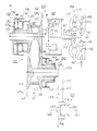
図2は本発明の実施の形態における無段変速機の概念図である。
【0020】
図に示されるように、無段変速機10は、ベルト式の変速機構102、前後進切換装置103、ロックアップクラッチ105が内蔵されたトルクコンバータ106、カウンタシャフト107及びディファレンシャル装置109を備える。
【0021】
前記トルクコンバータ106は、図示されないエンジンの出力軸110にフロントカバー117を介して連結されたポンプインペラ111、入力軸112に連結されたタービンランナ113、及びワンウェイクラッチ115を介して支持されたステータ116を備える。そして、前記ロックアップクラッチ105は、入力軸112とフロントカバー117との間に配設される。なお、120はロックアップクラッチプレート104と入力軸112との間に配設されたダンパスプリング、121はポンプインペラ111に連結されて駆動されるオイルポンプである。
【0022】
前記変速機構102は、プライマリプーリ126、セカンダリプーリ131、及び前記プライマリプーリ126とセカンダリプーリ131との間に張設された金属製のベルト132を有する。そして、前記プライマリプーリ126は、プライマリシャフト122に固定された固定シーブ123、及び前記プライマリシャフト122に対して軸方向に摺(しゅう)動自在に支持された可動シーブ125から成り、セカンダリプーリ131は、セカンダリシャフト127に固定された固定シーブ129、及び前記セカンダリシャフト127に対して軸方向に摺動自在に支持された可動シーブ130から成る。
【0023】
また、可動シーブ125の背面にはダブルピストンから成る第1の駆動手段としての油圧サーボ133が、可動シーブ130の背面にはシングルピストンから成る第2の駆動手段としての油圧サーボ135が配設される。なお、本実施の形態においては、前記第1、第2の駆動手段として油圧サーボ133、135が使用されるようになっているが、該油圧サーボ133、135に代えて電動機を使用することもできる。
【0024】
前記油圧サーボ133は、プライマリシャフト122に固定されたシリンダ部材136及び反力支持部材137、並びに可動シーブ125の背面に固定された筒状部材139及びピストン部材140を備え、前記筒状部材139、反力支持部材137、及び可動シーブ125の背面によって第1の油室141が、シリンダ部材136及びピストン部材140によって第2の油室142が形成される。
【0025】
そして、前記第1、第2の油室141、142が連通孔137aによって互いに連通させられるので、油圧サーボ133には、油圧サーボ135と同じ油圧を使用することによって、油圧サーボ135に発生させられる軸力のほぼ2倍の軸力が発生させられる。
【0026】
一方、前記油圧サーボ135は、セカンダリシャフト127に固定された反力支持部材143、及び可動シーブ130の背面に固定された筒状部材145を備え、前記反力支持部材143、筒状部材145及び可動シーブ130の背面によって1個の油室146が形成されるとともに、可動シーブ130と反力支持部材143との間にプリロード用のスプリング147が配設される。
【0027】
前記前後進切換装置103は、ダブルピニオンプラネタリギヤ150、リバースブレーキB及びダイレクトクラッチCを有する。前記ダブルピニオンプラネタリギヤ150において、サンギヤSと入力軸112とが連結され、第1、第2のピニオンP1、P2を支持するキャリヤCRと固定シーブ123とが連結され、リングギヤRと前記リバースブレーキBとが連結され、キャリヤCRとリングギヤRとが前記ダイレクトクラッチCを介して連結される。
【0028】
そして、前記カウンタシャフト107には、大ギヤ151及び小ギヤ152が固定され、前記大ギヤ151は、セカンダリシャフト127に固定されたギヤ153と噛(し)合し、また、小ギヤ152は、ディファレンシャル装置109のギヤ155と噛合する。前記ディファレンシャル装置109においては、前記ギヤ155を備えたデフケース166に支持されたデフギヤ156の回転が、左右のサイドギヤ157、159を介して左右の車軸160、161に伝達される。
【0029】
また、固定シーブ123の外周部には、多数の凹凸部123aが歯切りによって等間隔に形成され、前記凹凸部123aに臨ませて、図示されないケースに固定された電磁ピックアップから成るプライマリプーリ回転速度センサ162が配設される。前記固定シーブ129の外周部には、多数の凹凸部129aが歯切りによって等間隔に形成され、前記凹凸部129aに臨ませて、前記ケースに固定された電磁ピックアップから成るセカンダリプーリ回転速度センサ、すなわち、車速センサ44が配設される。したがって、該車速センサ44によって車両の走行条件を表す車速Vを、プライマリプーリ回転速度センサ162によって入力プーリ回転速度をそれぞれ検出することができる。
【0030】
また、前記フロントカバー117に近接させて前記ケースに固定された電磁ピックアップから成るエンジン回転速度センサ165が配設され、該エンジン回転速度センサ165によってエンジン負荷を表すエンジン回転速度NE を検出することができる。
【0031】
前記構成の無段変速機10において、前記エンジンを駆動することによって発生させられた回転は、トルクコンバータ106及び前後進切換装置103を介して変速機構102に伝達され、該変速機構102において変速が行われた後、ギヤ153、大ギヤ151及び小ギヤ152を介してディファレンシャル装置109に伝達される。そして、前記前後進切換装置103において、リバースブレーキBを解放した状態でダイレクトクラッチCを係合させると、ダブルピニオンプラネタリギヤ150は直結状態になり、入力軸112に伝達された回転はそのままプライマリプーリ126に伝達され、車両が前進させられる。また、リバースブレーキBを係合させた状態でダイレクトクラッチCを解放すると、入力軸112に伝達された回転は、逆転させられた状態でプライマリプーリ126に伝達され、車両が後退させられる。
【0032】
そして、シフトアップの変速を行う場合、油圧サーボ133に油圧が供給され、前記プライマリプーリ126の有効径が小さくされ、セカンダリプーリ131の有効径が大きくされる。その結果、変速比が小さくされる。また、シフトダウンの変速を行う場合、油圧サーボ133の油圧がドレーンされ、前記プライマリプーリ126の有効径が大きくされ、セカンダリプーリ131の有効径が小さくされる。その結果、変速比が大きくされる。
【0033】
次に、前記無段変速機10の制御装置について説明する。
【0034】
図3は本発明の実施の形態における無段変速機の制御装置のブロック図である。
【0035】
図において、12は無段変速機10(図2)の全体の制御を行う自動変速機制御部、13は図示されないエンジンの全体の制御を行うエンジン制御部、14はナビゲーション装置である。
【0036】
また、40は車両・運転者操作情報検出部であり、該車両・運転者操作情報検出部40は、ステアリングセンサ24、ウインカセンサ41、アクセルセンサ42、ブレーキセンサ43、車速Vを検出する車速センサ44、運転者による加速要求を表すスロットル開度を検出するスロットル開度センサ45、及び運転者がシフトレバー等の選速手段を操作することによって選択されたレンジを検出するシフトポジションセンサ46を備える。なお、前記ウインカセンサ41、アクセルセンサ42、ブレーキセンサ43、スロットル開度センサ45及びシフトポジションセンサ46等によって運転者による車両の操作情報を検出する運転者操作情報検出手段が構成される。
【0037】
そして、48は車両の前方を監視する前方監視装置、49は道路の車線を表す表示線を認識する表示線認識装置、50は車両の周辺を監視する周辺監視装置、51はRAM、52はROMである。なお、RAM51及びROM52によって記録手段が構成される。また、前記レンジとして、ニュートラルレンジ(N)、前進レンジ(D)、ローレンジ(L)、後進レンジ(R)及びパーキングレンジ(P)を選択することができる。なお、前記前方監視装置48は、レーザーレーダ、ミリ波レーダ、超音波センサ等、又はそれらの組合せから成り、自車周辺情報として車間距離La、車間時間、先行車に対する接近速度Va、一時停止箇所(非優先道路から優先道路への進入箇所、踏切、赤の信号が点滅する交差点等)に対する接近速度Vb、障害物に対する接近速度等を算出する。また、前記周辺監視装置50は、自車周辺情報として車両の前方の画像をCCD、C−MOS等のカメラによって撮影し、撮影によって得られた路上標識、信号機等の画像データを処理して周辺の車両数、白線位置、信号機の色等を判断する。
【0038】
前記ナビゲーション装置14は、現在位置を検出する現在位置検出部15、道路データ等の各種のデータが記録された記録媒体としてのデータ記録部16、入力された情報に基づいて、ナビゲーション処理等の各種の演算処理を行うナビゲーション処理部17、入力部34、表示部35、音声入力部36、音声出力部37及び通信部38を有する。
【0039】
そして、前記現在位置検出部15は、GPS21、地磁気センサ22、距離センサ23、ステアリングセンサ24、ビーコンセンサ25、ジャイロセンサ26、図示されない高度計等から成る。
【0040】
前記GPS21は、人工衛星によって発生させられた電波を受信することによって地球上における現在位置を検出し、前記地磁気センサ22は、地磁気を測定することによって車両が向いている方位を検出し、前記距離センサ23は、道路上の所定の位置間の距離等を検出する。前記距離センサ23としては、例えば、車輪の回転数を測定し、該回転数に基づいて距離を検出するもの、加速度を測定し、該加速度を2回積分して距離を検出するもの等を使用することができる。
【0041】
また、前記ステアリングセンサ24は舵(だ)角を検出し、前記ステアリングセンサ24として、例えば、図示されないステアリングホイールの回転部に取り付けられた光学的な回転センサ、回転抵抗センサ、図示されない車輪に取り付けられた角度センサ等が使用される。
【0042】
そして、前記ビーコンセンサ25は、道路に沿って配設されたビーコンからの位置情報を受信することによって現在位置を検出する。前記ジャイロセンサ26は、車両の回転角速度、すなわち、旋回角を検出し、前記ジャイロセンサ26として、例えば、ガスレートジャイロ、振動ジャイロ等が使用される。そして、ジャイロセンサ26によって検出された旋回角を積分することにより、車両が向いている方位を検出することができる。
【0043】
なお、前記GPS21及びビーコンセンサ25は、それぞれ単独で現在位置を検出することができる。そして、距離センサ23によって検出された距離と、地磁気センサ22及びジャイロセンサ26によって検出された方位とを組み合わせることにより現在位置を検出することもできる。また、距離センサ23によって検出された距離と、ステアリングセンサ24によって検出された舵角とを組み合わせることにより現在位置を検出することもできる。
【0044】
前記データ記録部16は、地図データファイル、交差点データファイル、ノードデータファイル、道路データファイル、写真データファイル、及び各地域のホテル、ガソリンスタンド、観光地案内等の施設の情報が記録された施設情報データファイルから成るデータベースを備える。そして、前記各データファイルには、経路を検索するためのデータのほか、前記表示部35の画面に、検索した経路に沿って案内図を表示したり、交差点又は経路における特徴的な写真、コマ図等を表示したり、次の交差点までの距離、次の交差点における進行方向等を表示したり、他の案内情報を表示したりするための各種のデータが記録される。なお、前記データ記録部16には、所定の情報を音声出力部37によって出力するための各種のデータも記録される。
【0045】
ところで、前記交差点データファイルには各交差点に関する交差点データが、ノードデータファイルにはノード点に関するノードデータが、道路データファイルには道路に関する道路データがそれぞれ記録される。前記ノードデータは、少なくとも道路の位置及び形状を構成するものであり、実際の道路の分岐点(交差点、T字路等を含む)、ノード点、及び各ノード点間を連結するリンクを示すデータから成る。なお、前記ノード点は少なくとも道路の屈曲点の位置を示し、分岐点及びノード点は少なくとも緯度、経度及び高度で表される。
【0046】
そして、前記道路データによって、道路の構造を示す項目については、幅員、カント、バンク、路面の状態、道路の車線数、車線数の減少する地点、幅員の狭くなる地点等が、コーナ等の道路の形状を示す項目については、曲率半径、交差点、T字路、コーナの入口等が、道路属性については、踏切、高速道路出口ランプウェイ、高速道路の料金所、降坂路、登坂路、道路種別(国道、一般道、高速道等)等がそれぞれ表される。
【0047】
また、前記ナビゲーション処理部17は、ナビゲーション装置14の全体の制御を行うCPU31、該CPU31が各種の演算処理を行うに当たってワーキングメモリとして使用されるRAM32、及び制御プログラムのほか、目的地までの経路の検索、経路中の走行案内、特定区間の決定等を行うための各種のプログラムが記録された記録媒体としてのROM33から成るとともに、前記ナビゲーション処理部17に、前記入力部34、表示部35、音声入力部36、音声出力部37及び通信部38が接続される。
【0048】
なお、前記データ記録部16及びROM33は、図示されない磁気コア、半導体メモリ等によって構成される。また、前記データ記録部16及びROM33として、磁気テープ、磁気ディスク、フロッピーディスク、磁気ドラム、CD、MD、DVD、光ディスク、ICカード、光カード等の各種の記録媒体を使用することもできる。
【0049】
本実施の形態においては、前記ROM33に各種のプログラムが記録され、前記データ記録部16に各種のデータが記録されるようになっているが、前記プログラム及びデータを同じ外部の記録媒体に記録することもできる。この場合、例えば、前記ナビゲーション処理部17に図示されないフラッシュメモリを配設し、前記外部の記録媒体から前記プログラム及びデータを読み出してフラッシュメモリに書き込むこともできる。したがって、外部の記録媒体を交換することによって前記プログラム及びデータを更新することができる。また、自動変速機制御部12の制御プログラム等も前記外部の記録媒体に記録することができる。このように、各種の記録媒体に記録されたプログラムを起動し、データに基づいて各種の処理を行うことができる。
【0050】
さらに、前記通信部38は、FM送信装置、電話回線等との間で各種のデータの送受信を行うためのものであり、例えば、図示されない情報センサ等によって渋滞等の道路状況情報、交通事故情報、GPS21の検出誤差を検出するD−GPS情報等の各種のデータを受信する。
【0051】
そして、前記入力部34は、走行開始時の位置を修正したり、目的地を入力したりするためのものであり、前記入力部34として、表示部35と別に配設されたキーボード、マウス、バーコードリーダ、ライトペン、遠隔操作用のリモートコントロール装置等を使用することができる。また、前記入力部34は、表示部35の図示されないディスプレイに画像で表示されたキー又はメニューにタッチすることにより入力を行うタッチパネルによって構成することもできる。
【0052】
そして、前記表示部35には、操作案内、操作メニュー、操作キーの案内、目的地までの経路、走行する経路に沿った案内等が表示される。前記表示部35としては、CRTディスプレイ、液晶ディスプレイ、プラズマディスプレイ、フロントガラスにホログラムを投影するホログラム装置等を使用することができる。
【0053】
また、音声入力部36は、図示されないマイクロホン等によって構成され、音声によって必要な情報を入力することができる。さらに、音声出力部37は、図示されない音声合成装置及びスピーカを備え、音情報、例えば、音声合成装置によって合成された音声から成る案内情報、変速情報等をスピーカから出力し、運転者に知らせる。なお、音声合成装置によって合成された音声のほかに、各種の音、及びあらかじめテープ、メモリ等に録音された各種の案内情報をスピーカから出力することもできる。
【0054】
前記構成のナビゲーション装置14において、CPU31の図示されない表示処理手段は、表示処理を行うことによって、表示部35の前記ディスプレイに案内画面を開き、該案内画面に現在位置及び周辺の地図を表示する。そして、運転者によって入力部34が操作されて目的地が設定されると、CPU31の図示されない経路検索処理手段は、経路検索処理を行うことによって、現在位置から目的地までの経路を検索し、経路が検索されると、前記表示処理手段は、表示処理を行うことによって、前記ディスプレイに案内画面を開き、該案内画面に現在位置、周辺の地図及び検索された経路を表示し、経路案内を開始する。したがって、運転者は、前記経路案内に従って車両を走行させることができる。
【0055】
また、前記自動変速機制御部12は、車両・運転者操作情報検出部40から車両情報及び操作情報を、ナビゲーション処理部17からナビ情報を読み込んで無段変速機10び制御を行う。さらに、前方監視装置48及び周辺監視装置50から自車周辺情報を読み込み、無段変速機10の制御を行うこともできる。
【0056】
そして、前記車両情報として、車速センサ44によって検出された車速V、スロットル開度センサ45によって検出されたスロットル開度、エンジン回転速度センサ165によって検出されたエンジン回転速度NE 、該エンジン回転速度NE に基づいて算出されたエンジン回転速度変化、車速Vに基づいて算出された車速変化(加速度、必要減速度)、図示されない油温センサによって検出されたATF温度、図示されないABSセンサによって検出された車輪ロック・アンロック、図示されない振動ジャイロセンサによって検出された縦ジャイロ、横ジャイロ又はロール角、図示されない水温センサによって検出されたエンジン水温、図示されない流量センサによって検出された吸入空気量、図示されない酸素(O2 )センサによって検出された酸素濃度等を利用することができる。
【0057】
また、操作情報として、アクセルセンサ42によって検出されたアクセル開度、該アクセル開度に基づいて算出された踏込速度情報又はキックダウンオン・オフ情報、図示されないキックダウンスイッチによって検出されたキックダウンオン・オフ情報、図示されないブレーキスイッチによって検出されたブレーキオン・オフ情報、前記ブレーキセンサ43によって検出された図示されないブレーキペダルの踏込強さ又は踏込速度Ve、図示されないブレーキ油圧センサによって検出された踏込強さ又は踏込速度Ve、前記ステアリングセンサ24によって検出された舵角、又は該舵角に基づいて算出された操舵速度、前記ウインカセンサ41によって検出されたウインカオフ、ウインカ右オン又はウインカ左オン、図示されないモードスイッチによって検出されたパワー(スポーツ)モード、ノーマル(エコノミー)モード、スノー(ホールド)モード又はオートモード、図示されないワイパスイッチによって検出されたワイパオフ、間欠オン、連続(ロー)オン又は連続(ハイ)オン、図示されないライトスイッチによって検出されたスモールライトオン、ヘッドライト(ロー)オン、ヘッドライト(ハイ)オン又はオートオン、シフトポジションセンサ46によって検出されたレンジ等を利用することができる。
【0058】
そして、ナビ情報として、データ記録部16に記録された前記交差点データ、ノードデータ、道路データ等を利用することができる。また、ナビ情報として、タウン情報又は地域情報、GPS21によって検出された時間(季節)、通信部38によって取得されたVICS渋滞レベル、FM多重によるD−GPS情報又は渋滞情報、図示されない携帯電話によって取得された地図情報、渋滞情報、行楽情報又は天気情報、衛星放送によって取得された地図情報、図示されないDSRCによって取得されたETC情報、料金決済情報、地図情報、交差点情報又はタウン情報、SS無線によって検出された車間情報等を利用することができる。
【0059】
また、自車周辺情報として、前記前方監視装置48によって検出された車間距離La、車間時間、先行車走行レーン又は障害物、前記周辺監視装置50によって検出された周辺の車両数、道路形状、白線位置、路肩位置、路面状態、道路標識、信号機、信号機の色、障害物等、図示されない超音波センサによって検出された障害物、図示されないマイクロ波センサによって検出された障害物、図示されないカメラによって検出された障害物等を利用することもできる。また、環境情報として、図示されない外気温センサによって検出された外気温度、図示されない日射センサによって検出された日射量等を利用することもできる。さらに、表示情報として、ビーコンセンサ25によって検出された信号機の色を利用することもできる。
【0060】
次に、通常変速制御を行う場合の自動変速機制御部12の動作について説明する。
【0061】
図4は本発明の実施の形態における変速線図である。なお、図において、横軸に車速Vを、縦軸にエンジン回転速度NE を採ってある。
【0062】
まず、自動変速機制御部12(図3)の図示されない通常変速制御処理手段は、選択されたレンジ、車速V、スロットル開度及びエンジン回転速度NE を読み込む。そして、前記通常変速制御処理手段は、ROM52に記録された図4に示される変速線図を参照し、選択されたレンジにおける走行条件及び加速要求に基づいて、エンジン回転速度NE の目標値、すなわち、目標エンジン回転速度NE * を算出する。
【0063】
次に、前記通常変速制御処理手段は、前記エンジン回転速度NE と目標エンジン回転速度NE * とを比較し、比較結果に基づいて変速出力を発生させ、所定の変速比を出力する。そして、エンジン回転速度NE が目標エンジン回転速度NE * より高い場合、所定の変速比によるシフトアップの変速を行い、エンジン回転速度NE と目標エンジン回転速度NE * とが等しい場合、変速は行わず、エンジン回転速度NE が目標エンジン回転速度NE * より低い場合、所定の変速比によるシフトダウンの変速を行う。
【0064】
ところで、図4において、最大変速比を表す線L1、最小変速比を表す線L2、スロットル開度が100〔%〕であるときの最大のエンジン回転数NE 、すなわち、最大使用回転速度を表す線L3、及びスロットル開度が0〔%〕であるときの最小のエンジン回転数NE 、すなわち、最小使用回転速度を表す線L4によって包囲される変速領域AR1が設定される。この場合、車速Vが大きくなるほど、又はスロットル開度が大きくなるほど、エンジン回転数NE が高くなるように変速マップが設定される。
【0065】
したがって、スロットル開度が100〔%〕で、エンジンが最大トルクを発生させる辺りまでは、線L1に沿って最大変速比が維持され、そこから線L3に沿って右上りの曲線を描いて、車速Vの増加と共にエンジン回転数NE が徐々に上昇する。そして、スロットル開度が小さくなるにつれて、右上りの曲線が下に移動する。
【0066】
一方、ある車速を維持した状態からスロットル開度が0〔%〕になると、エンジン回転数NE 及び変速比は、最小変速比の線L2に乗る。そして、前記車速より低い車速になると、変速比は線L4に沿って大きくなる。
【0067】
ところで、前記ナビゲーション装置14によって取得された、前記交差点データ、ノードデータ、道路データ等の道路情報に基づいて駆動力制御を行うようにした車両駆動力制御装置が提供されている。該車両駆動力制御装置は、前記ナビゲーション処理部17及び自動変速機制御部12を備える。そして、駆動力制御として、例えば、コーナ制御を行う場合、前記車両駆動力制御装置は、現在位置を検出し、該現在位置及び前記道路情報に基づいて道路形状を認識し、現在の車速V、現在位置からコーナまでの距離等に基づいて必要減速度を算出し、算出された必要減速度、及び車両の駆動力特性に基づいて推奨変速比を算出する。なお、前記必要減速度は、現在位置、現在の車速V及び道路形状から判断される速度過大度合いを表す情報である。
【0068】
続いて、前記車両駆動力制御装置は、算出された推奨変速比、車両情報、運転者の意図の推定結果等に基づいて、最適変速比を算出し、該最適変速比に基づいて変速制御を行い、前記変速機構の変速比を変化させてコーナ制御を行う。
【0069】
次に、前記ナビゲーション処理部17の動作について説明する。
【0070】
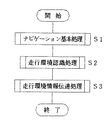
図5は本発明の実施の形態におけるナビゲーション処理部の動作を示すメインフローチャート、図6は本発明の実施の形態における走行環境認識処理のサブルーチンを示す図、図7は本発明の実施の形態における推奨車速マップを示す図、図8は本発明の実施の形態における減速線マップを示す図である。なお、図7において、横軸にノード半径Ri(i=1、2、…)を、縦軸に推奨車速Vri(i=1、2、…)を、図8において、横軸に区間距離Lを、縦軸に車速Vを採ってある。
【0071】
まず、ナビゲーション処理部17(図3)において、CPU31の図示されないナビゲーション基本処理手段は、ナビゲーション基本処理を行い、現在位置検出部15によって検出された現在位置を読み込むとともに、データ記憶部16の道路データファイルにアクセスし、該道路データファイルから、現在位置より前方の位置の道路データを手前から順に読み出す。この場合、該道路データには、各ノードの位置データ、各隣接するノード間を連結するリンクに付随する道路特性、リンクの長さ、ノードにおけるリンクの交差角度等が含まれる。
【0072】
続いて、前記CPU31の走行環境認識処理手段91(図1)は、走行環境認識処理を行い、車両の走行環境を認識する。そして、前記走行環境認識処理手段91の図示されないコーナ判定手段は、前記道路データに基づいてコーナ判定処理を行い、コーナ制御を必要とするコーナが有るかどうか、すなわち、コーナ制御を必要とするコーナに差し掛かっているかどうかを判断する。
【0073】
そのために、前記走行環境認識処理手段91の図示されない道路形状判断処理手段は、道路形状判断処理を行い、道路形状を判断する。すなわち、道路形状判断処理手段は、前記現在位置、及び前記現在位置より前方の位置の道路データに基づいて、制御リストを作成し、制御用データとして現在位置を含む道路上の所定の範囲(例えば、現在位置から1〜2〔km〕)内の各ノードごとに道路のノード半径Riを算出する。
【0074】
なお、目的地が設定されて経路が決定されている場合は、その経路に存在するノードについてのノード半径Riを、経路が決定されていない場合には、現在位置から、例えば、道なりに進んだ道路に存在するノードについてのノード半径Riを算出する。
【0075】
この場合、各ノードの絶対座標、及び前記各ノードに隣接する二つのノードの各絶対座標に基づいて演算処理が行われ、前記ノード半径Riが算出される。また、道路データとしてあらかじめデータ記憶部16にノード半径Riを、例えば、各ノードに対応させて格納しておき、必要に応じて前記ノード半径Riを読み出すこともできる。さらに、コーナの入口部分のノードに、コーナの全体の曲率半径のデータを持たせ、必要に応じて該データを読み出すこともできる。
【0076】
次に、CPU31は、前記所定の範囲内において前記ノード半径Riが閾(しきい)値より小さいノード、すなわち、対象ノードNdi(i=1、2、…)が検出されると、各対象ノードNdiにおいて車両を減速させる必要があると判断し、コーナ制御を必要とするコーナに差し掛かっていると判断する。
【0077】
そして、CPU31は、現在位置から前記各対象ノードNdiまでの区間距離Li(i=1、2、…)をリンクの長さに基づいて算出する。続いて、CPU31内の図示されない推奨車速算出手段は、図7に示される推奨車速マップを参照して、前記対象ノードNdiのノード半径Riに対応する推奨車速Vri(i=1、2、…)を読み込み、算出する。なお、前記推奨車速マップにおいては、ノード半径Riが小さくなると推奨車速Vriが低くされ、ノード半径Riが大きくなると推奨車速Vriが高くされる。
【0078】
本実施の形態においては、車両がコーナ制御を必要とするコーナに差し掛かると、現在位置からコーナに到達するまでに車速Vが前記推奨車速Vriになるような減速が必要であると判断される。
【0079】
続いて、前記CPU31は、図8に示される減速線マップを参照し、各対象ノードNdiについて、車両が各対象ノードNdiに到達するまでに車速Vが推奨車速Vriになるように減速線gi(i=1、2、…)を算出する。次に、前記CPU31は、前記各減速線giに基づいて決定される必要減速度βi(i=1、2、…)を算出する。なお、図8において、V0は現在の車速Vである。本実施の形態においては、減速線マップを参照することによって必要減速度βiを算出することができるようになっているが、所定の式によって必要減速度βiを算出することもできる。
【0080】
続いて、前記CPU31は、前記各対象ノードNdiの必要減速度βiのうちの最大値βmaxを算出するとともに、必要減速度βiが最大値βmaxになる対象ノードNdiにおける推奨車速VrXを算出し、前記最大値βmax及び推奨車速VrXを走行環境情報としてRAM32に記録する。なお、前記推奨車速VrXは、前方のコーナの形状、すなわち、コーナのきつさを表す情報であり、自動変速機制御部12の変速比制御における変速比に反映させるのが好ましい。
【0081】
そして、前記CPU31の走行環境情報伝達処理手段92は、走行環境情報伝達処理を行い、前記RAM32から最大値βmax及び推奨車速VrXを読み出し、所定の通信手段によって自動変速機制御部12に送る。本実施の形態においては、走行環境情報として最大値βmax及び推奨車速VrXを自動変速機制御部12に送るようになっているが、最大値βmaxに代えて、必要減速度βiが所定値を超えるたときに、減速が必要であることを表す減速フラグをオンにし、該減速フラグを自動変速機制御部12に送ることができる。また、本実施の形態においては、前方のコーナのきつさを表す情報として推奨車速VrXを自動変速機制御部12送るようになってているが、推奨車速VrXに代えて、コーナのきつさを示す同様の情報として、所定の距離あたりの互いに隣接するリンクの成す角度である旋回角度Θの総和ΣΘ、あらかじめ道路データファイルに記録されたコーナを旋回する度合いを示すコーナレベル情報等を自動変速機制御部12に送ることもできる。
【0082】
なお、前記コーナ判定処理において、コーナ制御を必要とするコーナがない場合、CPU31は減速が不要であることを表す減速不要フラグをオンにし、該減速不要フラグを自動変速機制御部12に送る。
【0083】
次に、図5のフローチャートについて説明する。
ステップS1 ナビゲーション基本処理を行う。
ステップS2 走行環境認識処理を行う。
ステップS3 走行環境情報伝達処理を行い、処理を終了する。
【0084】
次に、図6のフローチャートについて説明する。
ステップS2−1 ノード半径Riを算出する。
ステップS2−2 推奨車速Vriを算出する。
ステップS2−3 必要減速度βiを算出し、リターンする。
【0085】
このようにして、ナビゲーション処理部17から自動変速機制御部12に最大値βmax及び推奨車速VrXが送られると、自動変速機制御部12の図示されない協調変速制御処理手段は、協調変速制御処理を開始する。
【0086】
次に、協調変速制御処理について説明する。
【0087】
図9は本発明の実施の形態における自動変速機制御部の動作を示すメインフローチャート、図10は本発明の実施の形態における推奨変速比算出処理のサブルーチンを示す図、図11は本発明の実施の形態における最適変速比算出処理のサブルーチンを示す図、図12は本発明の実施の形態における通常走行モード処理のサブルーチンを示す図、図13は本発明の実施の形態におけるコーナ進入モード処理のサブルーチンを示す図、図14は本発明の実施の形態におけるシフトダウン制御処理のサブルーチンを示す図、図15は本発明の実施の形態におけるシフトアップ禁止制御処理のサブルーチンを示す図、図16は本発明の実施の形態におけるコーナ脱出モード処理のサブルーチンを示す図、図17は本発明の実施の形態における推奨変速比マップを示す図、図18は本発明の実施の形態における推奨変速比判断処理の動作を説明する図、図19は本発明の実施の形態における最適変速比判断処理の動作を説明する図である。なお、図17において、横軸に車速Vを、縦軸に減速度を、図18及び19において、横軸に距離を、縦軸に車速V及び変速比を採ってある。
【0088】
まず、前記協調変速制御処理手段の目標回転速度算出処理手段は、目標回転速度算出処理を行い、選択されたレンジ、車速V、スロットル開度及びエンジン回転速度NE を読み込み、ROM52(図3)に記録された図4に示される変速線図を参照し、選択されたレンジにおける車両の走行条件及び加速要求に基づいて目標エンジン回転速度NE * を算出する。
【0089】
ところで、平坦(たん)な道路において減速を行う場合と、登坂路又は降坂路において減速を行う場合とでは、同じ距離を走行させても減速度が異なる。例えば、登坂路において、運転者が車両を減速させようとした場合、抵抗が大きくなるのでシフトダウンの変速を行わなくても十分な減速が行われる。また、降坂路において、運転者が車両を減速させようとした場合、抵抗が小さくなるので積極的にシフトダウンの変速を行い、減速を行う必要がある。
【0090】
そこで、道路勾配を推定し、推定された道路勾配に基づいて前記最大値βmaxを補正するようにしている。そのために、前記協調変速制御処理手段の道路勾配推定処理手段及び勾配算出手段は、道路勾配推定処理を行い、前記スロットル開度、車速V、車両の実加速度α等に基づいて道路勾配を算出し、推定する。
【0091】
なお、該道路勾配は、次のようにして推定される。まず、車両駆動力が次の式によって算出される。
【0092】
車両駆動力=入力トルク×プーリ比×デフ・カウンタ減速比×トランスミッション効率÷(タイヤ半径)
ここで、トランスミッションイナーシャは、プライマリプーリ126(図2)系、ベルト132、セカンダリプーリ131系、カウンタシャフト107、ディファレンシャル装置109及びタイヤ系の各イナーシャを加算することによって得られる。
【0093】
次に、走行抵抗が次の式によって算出される。
【0094】
走行抵抗=転がり抵抗係数×車両重量×重力加速度+空気抵抗係数×前方投影面積×空気密度×(車速V)2 ÷2
続いて、基準加速度が次の式によって算出される。
【0095】
基準加速度=((車両駆動力)−(走行抵抗))÷((車両重量)+(トランスミッションイナーシャ)÷(タイヤ半径)2 )
さらに、前記基準加速度と車速Vから算出される実加速度との差に基づいて前記道路勾配が推定される。
【0096】
そして、前記協調変速制御処理手段の推奨変速比算出処理手段93(図1)は、推奨変速比算出処理を行い、道路形状に対応させて推奨変速比を算出する。そのために、前記推奨変速比算出処理手段93は、まず、道路勾配に基づいて前記最大値βmaxを補正する。ここで、前記道路勾配をθ〔%〕(登坂路の場合、負の値を、降坂路の場合、正の値を採る。)とし、道路勾配θに応じた補正関数をfg(θ)とすると、補正後の必要減速度Grは、
Gr=βmax+fg(θ)
になる。なお、補正関数fg(θ)は、
fg(θ)=θ/100
で近似される。
【0097】
この場合、道路勾配θに対応させて最大値βmaxが補正されるので、適切な必要減速度Grを得ることができる。したがって、適正なコーナ制御を行うことができる。
【0098】
続いて、前記推奨変速比算出処理手段93は、図17の推奨変速比マップを参照し、現在の車速V0において、前記必要減速度Grを得るための変速比Ipを推奨変速比Ipxとして算出する。なお、前記推奨変速比マップは、アクセルペダルが踏み込まれていないアクセル開放時ものであり、h1〜h4は、変速比Ipがそれぞれ1.8、1.2、0.8、0.5のときの車速Vと減速度との関係を示す線である。
【0099】
次に、前記推奨変速比算出処理手段93は、前記推奨変速比Ipxに、コーナのきつさ、及び道路勾配θに応じた上限変速比IpUを反映させ、コーナのきつさ、及び道路勾配θに対応させて推奨変速比IpLを算出する。本実施の形態においては、コーナのきつさを表す情報として推奨車速VrXがCPU31から送られる。そこで、前記推奨変速比算出処理手段93は、前記推奨車速VrX及び道路勾配θに応じて上限変速比IpUを算出し、前記推奨変速比Ipx及び上限変速比IpUのうちの小さい方を、上限変速比IpUを反映させた推奨変速比IpLとして算出する。
【0100】
この場合、推奨車速VrXが小さく、コーナがきついほど、また、道路勾配θが大きいほど前記上限変速比IpUは大きくされ、無段変速機10はアンダードライブ側で駆動される。また、推奨車速VrXが大きく、コーナが緩いほど、また、道路勾配θが小さいほど前記上限変速比IpUは小さくされ、無段変速機10はオーバードライブ側で駆動される。なお、コーナのきつさを表す情報として所定の距離あたりの旋回角度Θの総和ΣΘを利用した場合、総和ΣΘが大きく、コーナがきついほど、また、道路勾配θが大きいほど前記上限変速比IpUは大きくされ、無段変速機10はアンダードライブ側で駆動される。また、総和ΣΘが小さく、コーナが緩いほど、また、道路勾配θが小さいほど前記上限変速比IpUは小さくされ、無段変速機10はオーバードライブ側で駆動される。
【0101】
推奨車速VrXよりかなり高い車速Vでコーナに進入しようとしたときに、大きな推奨変速比Ipxで変速が行われると、過剰なエンジンブレーキが発生してしまう。ところが、本実施の形態においては、上限変速比IpUを反映させた推奨変速比IpLが算出されるので、過剰なエンジンブレーキ力が発生するのを防止することができる。
【0102】
このように、推奨変速比算出処理が行われると、図18に示されるような変速特性を得ることができる。図18において、ラインL1は車速Vを、ラインL2は必要減速度Grを、ラインL3、L4は推奨変速比Ipxを、ラインL5、L6は上限変速比IpUを、ラインL3、L6は推奨変速比IpLを表す。
【0103】
なお、前記CPU31から減速不要フラグが送られた場合、前記推奨変速比算出処理手段93は、推奨変速比IpLを、オーバードライブ走行時の変速比、すなわち、最小変速比Ipminにする。
【0104】
続いて、前記協調変速制御処理手段の最適変速比算出処理手段94は、最適変速比算出処理を行う。そのために、最適変速比算出処理手段94は、イグニッションオン・オフ時に初期化処理を行って、走行環境モードを通常走行モードに設定し、前記推奨変速比算出処理において算出された推奨変速比IpLに基づいて、走行環境モードを通常走行モード、コーナ進入モード及びコーナ脱出モード間において切り替えながら、最適変速比IpBを算出し、設定する。
【0105】
すなわち、前記最適変速比算出処理手段94は、走行環境モードが通常走行モード、コーナ進入モード及びコーナ脱出モードのうちのいずれのモードであるか判定し、走行環境モードが通常走行モードである場合、前記最適変速比算出処理手段94の通常走行モード処理手段は、通常走行モード処理を行い、走行環境モードがコーナ進入モードである場合、前記最適変速比算出処理手段94のコーナ進入モード処理手段は、コーナ進入モード処理を行い、走行環境モードがコーナ脱出モードである場合、前記最適変速比算出処理手段94のコーナ脱出モード処理手段は、コーナ脱出モード処理を行う。
【0106】
そして、走行環境モードが通常走行モードである場合、通常走行モード処理手段は、最適変速比IpBを初期化して最小変速比Ipminにする。次に、前記通常走行モード処理手段は、最適変速比IpB(最小変速比Ipmin)と前記推奨変速比IpLとを比較し、
IpB<IpL
である場合、前記推奨変速比IpLがアンダードライブ側に設定されているので、走行環境モードをコーナ進入モードに移行させる。
【0107】
該コーナ進入モードにおいて、コーナ進入モード処理手段は、コーナに対する運転者による減速意図がある場合、推奨変速比IpLを超えない範囲でシフトダウンの変速を行い、運転者がアクセルペダルを踏み込んでいる場合、推奨変速比IpLを超えない範囲でシフトアップの変速が行われるのを禁止する。
【0108】
そのために、コーナ進入モード処理手段のシフトダウン制御処理手段は、シフトダウン制御処理を行う。そして、シフトダウン制御処理手段は、アクセルセンサ42によって検出されたアクセル開度に基づいて、アクセルオフの動作が行われたかどうか、すなわち、コーナに対する運転者による減速意図があるかどうかを判断する。運転者の減速意図がある場合、前記最適変速比IpBを最小変速比Ipminからスイープアップさせ、徐々に大きくする。続いて、前記シフトダウン制御処理手段は、最適変速比IpBと推奨変速比IpLとを比較し、
IpB>IpL
である場合、推奨変速比IpLを最適変速比IpBにする。
【0109】
このように、コーナに対する運転者による減速意図がある場合、前記最適変速比IpBは、最小変速比Ipminから推奨変速比IpLになるまで徐々に大きくされ、オーバードライブ側からアンダードライブ側に変化させられる。
【0110】
また、アクセルオフの動作が行われず、アクセルオンの動作が行われている場合、コーナに対する運転者による減速意図がないので、シフトダウン制御処理手段はシフトダウン制御処理を終了する。なお、前記スイープアップは所定の周期(例えば、16〔ms〕)で行われる。
【0111】
そして、コーナ進入モード処理手段のシフトアップ禁止制御処理手段は、シフトアップ禁止制御処理を行い、シフトアップの変速が行われるのを禁止し、最適変速比IpBが小さくならないようにする。そのために、シフトアップ禁止制御処理手段は、現在の変速比IpNと推奨変速比IpLとを比較し、
IpN≦IpL
であると、次の式に従って、最適変速比IpB及び現在の変速比IpNのうちの大きい方を最適変速比IpBとする。
【0112】
IpB=max(IpB,IpN)
すなわち、現在の変速比IpN以上の推奨変速比IpLが算出された場合、最適変速比IpB及び現在の変速比IpNのうちの大きい方を最適変速比IpBとする。
【0113】
そして、現在の変速比IpNより小さい推奨変速比IpLが算出された場合、最適変速比IpBと推奨変速比IpLとを比較し、
IpB<IpL
である場合、推奨変速比IpLを最適変速比IpBにする。このように、シフトアップ禁止制御処理においては、最適変速比IpBを推奨変速比IpL及び現在の変速比IpNを超えない範囲で大きくし、シフトアップの変速を禁止する。このようにして、シフトアップ禁止制御処理が行われる。したがって、コーナ進入モードにおいて、アクセルペダルが踏み込まれていて解放されたときに、シフトアップの変速(オフアップの変速)が行われることがなくなるので、運転者が空走感を覚えるのを防止することができる。
【0114】
続いて、コーナ進入モード処理手段は、最適変速比IpBと推奨変速比IpLとを比較し、
IpB>IpL
である場合、走行環境モードをコーナ脱出モードに移行させる。
【0115】
次に、該コーナ脱出モードにおいて、コーナ脱出モード処理手段は、コーナに対する運転者によるシフトアップ意図がある場合、最適変速比IpBは、運転者が違和感を覚えることがない変速速度範囲で滑らかに、かつ、推奨変速比IpLを下回らない範囲で小さくされ、シフトアップの変速が行われる。
【0116】
そのために、コーナ脱出モード処理手段のシフトアップ制御処理手段は、シフトアップ制御処理を行う。そして、シフトアップ制御処理手段は、車速センサ44によって検出された車速Vに基づいて、増速状態が継続されているかどうかを判断し、増速状態が継続されている場合にコーナに対する運転者によるシフトアップ意図があると判断する。また、アクセルセンサ42によって検出されたアクセル開度に基づいて、アクセルペダルの戻し操作があるかどうかを判断し、アクセルペダルの戻し操作がある場合にコーナに対する運転者によるシフトアップ意図があると判断することもできる。
【0117】
ところで、運転者がアクセルペダルを大きく踏み込み、通常変速制御処理手段によって算出された通常の目標エンジン回転速度NE * が最適変速比IpBに従って算出された目標エンジン回転速度、すなわち、最適目標エンジン回転速度NE * Bより高くなっ場合、最適変速比IpBを小さくしてオーバードライブ側に変化させても、変速動作は行われず、運転者に違和感を覚えさせない。したがって、この場合も、推奨変速比IpLより小さくならない範囲で最適変速比IpBを小さくすることができる。
【0118】
そして、コーナ脱出モード中に推奨変速比IpLが最適変速比IpBより大きくなり、アンダードライブ側になると、コーナ脱出モード処理手段は走行環境モードをコーナ進入モードに移行させる。また、コーナ脱出モード中に最適変速比IpBが十分小さくなり、オーバードライブ側になると、コーナ脱出モード処理手段は、シフトアップの変速が終了したと判断し、走行環境モードを通常走行モードに移行させる。
【0119】
このようにして、最適変速比算出処理が行われると、図19に示されるような変速特性を得ることができる。図19において、ラインL1は車速Vを、ラインL3、L6は推奨変速比IpLを、ラインL7、L8はアクセル開度を、ラインL9、L10は最適変速比IpBを表す。
【0120】
ところで、車両が通常走行する走行環境、車両がコーナに進入する走行環境、車両がコーナから脱出する走行環境等が考えられるが、前記各走行環境に合わない処理が行われると、処理速度が低くなってしまう。ところが、本実施の形態においては、走行環境モードが通常走行モード、コーナ進入モード及びコーナ脱出モードのうちのいずれのモードであるが判定され、各走行環境に対応した処理が行われ、無駄な処理が行われることがないので、処理速度を高くすることができる。
【0121】
また、運転者がアクセルペダルを踏み込んだ状態からアクセルペダルを戻し始めたときに、シフトアップの変速が行われると、適正なコーナ制御を行うことができないが、本実施の形態においては、コーナ進入モードにおいてシフトアップの変速が禁止されるので、適正なコーナ制御を行うことができる。
【0122】
このようにして、最適変速比算出処理が行われると、自動変速機制御部12の変速制御処理手段95は、変速制御処理を行う。そして、前記変速制御処理手段95は、通常変速制御処理手段によって算出された目標エンジン回転速度NE * と、前記最適変速比IpBに従って算出された最適目標エンジン回転速度NE * Bとを比較し、いずれか大きい方の値を最終的な目標エンジン回転速度、すなわち、最終目標エンジン回転速度NE * Eとして決定し、該最終目標エンジン回転速度NE * Eに基づいて変速制御を行う。なお、前記最適目標エンジン回転速度NE * Bは、セカンダリプーリ回転速度をNsとすると、
NE * B=IpB・Ns
で表される。
【0123】
コーナ制御と共に、登坂制御、降坂制御、車間距離制御等の他の走行環境による車両駆動力制御が行われている場合、それらによる各目標エンジン回転速度NE * 及び前記最適目標エンジン回転速度NE * Bのうちの大きい方の値を最終目標エンジン回転速度とする。
【0124】
なお、コーナ制御が行われていない場合、最適変速比IpBはオーバードライブ側に設定され、前述されたように目標エンジン回転速度NE * 及び最適目標エンジン回転速度NE * Bのいずれか大きい方の値を最終目標エンジン回転速度NE * Eとすると、通常変速制御処理手段は通常変速制御を行う。
【0125】
本実施の形態においては、ナビゲーション処理部17において、道路情報を取得し、道路形状を認識し、必要減速度の最大値βmax及び推奨車速VrXを算出し、該必要減速度の最大値βmax及び推奨車速VrXを自動変速機制御部12に送り、該自動変速機制御部12において、推奨変速比IpLを算出し、最適変速比IpBを算出して変速制御を行うようになっているので、ナビゲーション装置14の汎用性を高くすることができる。
【0126】
また、ナビゲーション処理部17と自動変速機制御部12との間の通信量を少なくすることができるので、自動変速機制御部12の処理量を少なくすることができる。したがって、自動変速機制御部12のCPUの処理能力を高くする必要がなくなるので、車両駆動力制御装置のコストを低くすることができる。
【0127】
次に、図9のフローチャートについて説明する。
ステップS11 目標回転速度算出処理を行う。
ステップS12 道路勾配推定処理を行う。
ステップS13 推奨変速比算出処理を行う。
ステップS14 最適変速比算出処理を行う。
ステップS15 変速制御処理を行い、処理を終了する。
【0128】
次に、図10のフローチャートについて説明する。
ステップS13−1 必要減速度の最大値βmaxを補正する。
ステップS13−2 必要減速度Grを得るための推奨変速比Ipxを算出する。
ステップS13−3 推奨変速比Ipxに上限変速比IpUを反映させ、リターンする。
【0129】
次に、図11のフローチャートについて説明する。
ステップS14−1 走行環境モードが通常走行モード、コーナ進入モード及びコーナ脱出モードのうちのいずれのモードであるか判定する。走行環境モードが通常走行モードである場合はステップS14−2に、走行環境モードがコーナ進入モードである場合はステップS14−3に、走行環境モードがコーナ脱出モードである場合はステップS14−4に進む。
ステップS14−2 通常走行モード処理を行い、リターンする。
ステップS14−3 コーナ進入モード処理を行い、リターンする。
ステップS14−4 コーナ脱出モード処理を行い、リターンする。
【0130】
次に、図12のフローチャートについて説明する。
ステップS14−2−1 最適変速比IpBを初期化して最小変速比Ipminとする。
ステップS14−2−2 最適変速比IpBが推奨変速比IpLより小さいかどうかを判断する。最適変速比IpBが推奨変速比IpLより小さい場合はステップS14−2−3に進み、最適変速比IpBが推奨変速比IpL以上である場合はリターンする。
ステップS14−2−3 走行環境モードをコーナ進入モードに移行させ、リターンする。
【0131】
次に、図13のフローチャートについて説明する。
ステップS14−3−1 シフトダウン制御処理を行う。
ステップS14−3−2 シフトアップ禁止制御処理を行う。
ステップS14−3−3 最適変速比IpBが推奨変速比IpLより大きいかどうかを判断する。最適変速比IpBが推奨変速比IpLより大きい場合はステップS14−3−4に進み、最適変速比IpBが推奨変速比IpL以下である場合はリターンする。
ステップS14−3−4 走行環境モードをコーナ脱出モードに移行させ、リターンする。
【0132】
次に、図14のフローチャートについて説明する。
ステップS14−3−1−1 アクセルオフの動作が行われたかどうかを判断する。アクセルオフの動作が行われた場合はステップS14−3−1−2に進み、行われていない場合はリターンする。
ステップS14−3−1−2 最適変速比IpBをスイープアップさせる。
ステップS14−3−1−3 最適変速比IpBが推奨変速比IpLより大きいかどうかを判断する。最適変速比IpBが推奨変速比IpLより大きい場合はステップS14−3−1−4に、最適変速比IpBが推奨変速比IpL以下である場合はリターンする。
ステップS14−3−1−4 推奨変速比IpLを最適変速比IpBとし、リターンする。
【0133】
次に、図15のフローチャートについて説明する。
ステップS14−3−2−1 現在の変速比IpNが推奨変速比IpL以下であるかどうかを判断する。現在の変速比IpNが推奨変速比IpL以下である場合はステップS14−3−2−2に、現在の変速比IpNが推奨変速比IpLより大きい場合はステップS14−3−2−3に進む。
ステップS14−3−2−2 最適変速比IpB及び現在の変速比IpNのうちの大きい方の値max(IpB,IpN)を最適変速比IpBにする。
ステップS14−3−2−3 最適変速比IpBが推奨変速比IpLより小さいかどうかを判断する。最適変速比IpBが推奨変速比IpLより小さい場合はステップS14−3−2−4に、最適変速比IpBが推奨変速比IpL以上である場合はリターンする。
ステップS14−3−2−4 推奨変速比IpLを最適変速比IpBとし、リターンする。
【0134】
次に、図16のフローチャートについて説明する。
ステップS14−4−1 シフトアップ制御処理を行う。
ステップS14−4−2 最適変速比IpBが推奨変速比IpLより小さいかどうかを判断する。最適変速比IpBが推奨変速比IpLより小さい場合はステップS14−4−3に、最適変速比IpBが推奨変速比IpL以上である場合はステップS14−4−4に進む。
ステップS14−4−3 走行環境モードをコーナ進入モードに移行させ、リターンする。
ステップS14−4−4 シフトアップの変速が終了したかどうかを判断する。
シフトアップの変速が終了した場合はステップS14−4−5に進み、終了していない場合はリターンする。
ステップS14−4−5 走行環境モードを通常走行モードに移行させ、リターンする。
【0135】
なお、前記無段変速機には、ベルト式無段変速機、出力が零(0)になる状態に自己収束する無段変速機、トロイダル無段変速機、静油圧式無段変速機等が含まれる。また、本発明の車両駆動力制御装置は、無段変速機に限られるものではなく、トルクコンバータ及びプラネタリギヤを備えた有段の自動変速機、機械式変速機を自動化した有段の自動変速機、更に、電気自動車及びハイブリッド型車両も含めた概念である。そして、有段の自動変速機を使用する場合、変速比を変速段に置き換えることができる。電気自動車及びハイブリッド型車両の場合には、変速制御処理手段に代えてモータ回生量制御手段を使用することができる。この場合、ナビゲーション装置からの走行環境情報に基づいてモータの回生制御量が決定される。また、無段変速機を備えたハイブリッド型車両の変速比も同様に制御される。
【0136】
【発明の効果】
以上詳細に説明したように、本発明によれば、車両駆動力制御装置においては、ナビゲーション装置及び自動変速機制御部によって構成される。
そして、前記ナビゲーション装置は、道路情報を記録するデータ記録部と、車両の現在位置を検出する現在位置検出部と、車速を検出する車速センサと、記録された道路情報及び検出された車両の現在位置に基づいて、車両の前方に存在するコーナの推奨車速を算出し、該推奨車速、現在位置からコーナまでの区間距離、及び検出された車速に基づいて、推奨車速まで減速させるのに必要な減速度を表す必要減速度を算出し、算出された必要減速度を前記自動変速機制御部に送信するナビゲーション処理部とを有する。
また、前記自動変速機制御部は、ナビゲーション処理部から受信した必要減速度に基づいて推奨変速比を算出する推奨変速比算出処理手段と、算出された推奨変速比への変速制御を行う変速制御処理手段とを備える。
【0137】
この場合、ナビゲーション装置は、車両の前方に存在するコーナの推奨車速を算出し、該推奨車速、現在位置からコーナまでの区間距離、及び検出された車速に基づいて、推奨車速まで減速させるのに必要な減速度を表す必要減速度を算出し、算出された必要減速度を自動変速機制御部に送信する。また、自動変速機制御部は、ナビゲーション処理部から受信した必要減速度に基づいて推奨変速比を算出し、算出された推奨変速比への変速制御を行う。
【0138】
したがって、ナビゲーション装置の汎用性を高くすることができる。
【0139】
また、ナビゲーション装置と自動変速機制御部との間の通信量を少なくすることができるので、自動変速機制御部の処理量を少なくすることができる。したがって、自動変速機制御部のCPUの処理能力を高くする必要がなくなるので、車両駆動力制御装置のコストを低くすることができる。
【図面の簡単な説明】
【図1】本発明の実施の形態における車両駆動力制御装置の機能ブロック図である。
【図2】本発明の実施の形態における無段変速機の概念図である。
【図3】本発明の実施の形態における無段変速機の制御装置のブロック図である。
【図4】本発明の実施の形態における変速線図である。
【図5】本発明の実施の形態におけるナビゲーション処理部を示すメインフローチャートである。
【図6】本発明の実施の形態における走行環境認識処理のサブルーチンを示す図である。
【図7】本発明の実施の形態における推奨車速マップを示す図である。
【図8】本発明の実施の形態における減速線マップを示す図である。
【図9】本発明の実施の形態における自動変速機制御部の動作を示すメインフローチャートである。
【図10】本発明の実施の形態における推奨変速比算出処理のサブルーチンを示す図である。
【図11】本発明の実施の形態における最適変速比算出処理のサブルーチンを示す図である。
【図12】本発明の実施の形態における通常走行モード処理のサブルーチンを示す図である。
【図13】本発明の実施の形態におけるコーナ進入モード処理のサブルーチンを示す図である。
【図14】本発明の実施の形態におけるシフトダウン制御処理のサブルーチンを示す図である。
【図15】本発明の実施の形態におけるシフトアップ禁止制御処理のサブルーチンを示す図である。
【図16】本発明の実施の形態におけるコーナ脱出モード処理のサブルーチンを示す図である。
【図17】本発明の実施の形態における推奨変速比マップを示す図である。
【図18】本発明の実施の形態における推奨変速比判断処理の動作を説明する図である。
【図19】本発明の実施の形態における最適変速比判断処理の動作を説明する図である。
【符号の説明】
12 自動変速機制御部
17 ナビゲーション処理部
91 走行環境認識処理手段
92 走行環境情報伝達処理手段
93 推奨変速比算出処理手段
94 最適変速比算出処理手段
95 変速制御処理手段[0001]
TECHNICAL FIELD OF THE INVENTION
The present invention relates to a vehicle driving force control device and a vehicle driving force control method.
[0002]
[Prior art]
2. Description of the Related Art Conventionally, in a vehicle equipped with an automatic transmission, rotation generated by driving an engine is transmitted to a speed change mechanism, a speed change is performed in the speed change mechanism, and rotation after the speed change is performed on a drive wheel. To make the vehicle run.
[0003]
The automatic transmission includes a stepped transmission and a continuously variable transmission. In the stepped transmission, a gear element for inputting rotation to a planetary gear unit and a gear element for outputting rotation from the planetary gear unit. The gear ratio of the transmission mechanism is changed in a stepped manner by changing the combination of the above-described steps. By changing the position of the belt in the direction, that is, the effective diameter, the speed ratio of the speed change mechanism is continuously changed. For this purpose, the primary pulley and the secondary pulley each include a fixed sheave and a movable sheave, and the movable sheave is moved by a driving means such as a hydraulic servo or an electric motor to change the effective diameter.
[0004]
Meanwhile, there is provided a vehicle driving force control device that controls driving force of a vehicle based on road information acquired by a navigation device, that is, performs driving force control. The vehicle driving force control device includes a navigation processing unit that controls the navigation device, and an automatic transmission control unit that controls an automatic transmission. Then, as the driving force control, for example, when the vehicle approaches a corner, when performing corner control for decelerating the vehicle as necessary, the vehicle driving force control device includes the current position of the vehicle (own vehicle), That is, the shape of the road ahead (hereinafter referred to as “road shape”) is recognized based on the current position and the road information, and the vehicle stabilizes the corner based on the current vehicle speed, the distance from the current position to the corner, and the like. The deceleration required to decelerate to the vehicle speed at which the vehicle travels, that is, the required deceleration is calculated, and the recommended gear ratio is calculated based on the calculated required deceleration and the driving force characteristics of the vehicle. The required deceleration is information indicating the degree of excessive speed, which is determined from the current position, the current vehicle speed, and the road shape, and indicates that the speed is higher as the deceleration control is performed.
[0005]
Subsequently, the vehicle driving force control device calculates an optimum gear ratio based on the calculated recommended gear ratio, current position, vehicle information such as the current vehicle speed, a result of estimating a driver's intention, and the like. A shift control is performed based on a speed ratio, and the corner control is performed by changing a speed ratio of the speed change mechanism.
[0006]
[Problems to be solved by the invention]
However, in the conventional vehicle driving force control device, the navigation processing unit and the automatic transmission control unit perform various functions such as calculation of the required deceleration, calculation of the recommended gear ratio, calculation of the optimum gear ratio, and gear shift control. Of the navigation device, if the functions are not properly assigned, the general usability of the navigation device becomes low, or the navigation processing unit and the automatic transmission control unit The communication amount during this period becomes enormous, and the processing amount of the automatic transmission control unit increases.
[0007]
For example, in the navigation processing unit, road information is acquired, the current position and road information are sent to the automatic transmission control unit, and the automatic transmission control unit recognizes the road shape, calculates the required deceleration, and sets the recommended gear ratio. If the shift control is performed by performing the calculation and the calculation of the optimal gear ratio, the versatility of the navigation device is increased, but all the road information is transmitted, and the communication between the navigation processing unit and the automatic transmission control unit is performed. The communication volume of the automatic transmission becomes enormous, and the processing amount of the automatic transmission control unit increases. Therefore, it is necessary to increase the processing capacity of the CPU of the automatic transmission control unit, so that the cost of the vehicle driving force control device increases.
[0008]
In the navigation processing unit, the road information is acquired, the road shape is recognized, the required deceleration is calculated, and the recommended gear ratio is calculated. The recommended gear ratio is sent to the automatic transmission control unit, and the automatic transmission If the control unit calculates the optimal gear ratio and performs gear shift control, the content of the communication is only the value of the recommended gear ratio, so that the communication amount between the navigation processing unit and the automatic transmission control unit is reduced. The size of the automatic transmission control unit can be reduced, and the processing amount of the automatic transmission control unit can be reduced. Therefore, since it is not necessary to increase the processing capacity of the CPU of the automatic transmission control unit, the cost of the vehicle driving force control device can be reduced. However, in this case, the navigation processing unit calculates the required deceleration and calculates the recommended gear ratio. In particular, the calculation of the recommended gear ratio performs processing dependent on the driving system, driving force characteristics, and the like of each vehicle. Need arises. Therefore, a navigation device must be set for each vehicle, and the versatility of the navigation device is reduced.
[0009]
The present invention can solve the problems of the conventional vehicle driving force control device, increase the versatility of the navigation device, and increase the communication amount between the navigation processing unit and the automatic transmission control unit, and Vehicle driving force control device and vehicle driving force control method capable of reducing the processing amount of automatic transmission control unit, eliminating the need to increase the processing capacity of CPU of automatic transmission control unit, and reducing costs The purpose is to provide.
[0010]
[Means for Solving the Problems]
For this purpose, the vehicle driving force control device of the present invention includes a navigation device and an automatic transmission control unit.
The navigation device includes a data recording unit that records road information, a current position detection unit that detects a current position of the vehicle, a vehicle speed sensor that detects a vehicle speed, a recorded road information and a current position of the detected vehicle. Based on the position, a recommended vehicle speed of a corner existing in front of the vehicle is calculated, and based on the recommended vehicle speed, the section distance from the current position to the corner, and the detected vehicle speed, it is necessary to decelerate to the recommended vehicle speed. A navigation processing unit for calculating a required deceleration representing the deceleration and transmitting the calculated required deceleration to the automatic transmission control unit.
The automatic transmission control unit includes a recommended gear ratio calculation processing unit that calculates a recommended gear ratio based on the required deceleration received from the navigation processing unit, and a gearshift control that performs gearshift control to the calculated recommended gear ratio. Processing means.
In another vehicle driving force control device of the present invention, the shift control processing means further includes a gradient calculating means for calculating a gradient of a road on which the vehicle travels.
The recommended gear ratio calculation processing means calculates a recommended gear ratio based on the required deceleration and the calculated road gradient.
[0011]
Still another vehicle driving force control device of the present invention includes a navigation device and an automatic transmission control unit.
The navigation device includes a data recording unit that records nodes and links that constitute a road; a current position detection unit that detects a current position of the vehicle; a vehicle speed sensor that detects a vehicle speed; Based on the current position of the vehicle, calculate the recommended vehicle speed of the node existing in front of the vehicle, calculate the sum of the angles formed by adjacent links, the recommended vehicle speed, the section distance from the current position to the node, And a navigation processing unit that calculates a required deceleration representing a deceleration required for deceleration based on the detected vehicle speed, and transmits the sum of angles formed by the links and the required deceleration to the automatic transmission control unit. Having.
The automatic transmission control unit includes a recommended gear ratio calculation processing unit that calculates a recommended gear ratio based on a sum of angles formed by the links and a required deceleration, and a gear ratio that performs a gear shift control to the calculated recommended gear ratio. Control processing means.
[0012]
In still another vehicle driving force control device according to the present invention, the automatic transmission control unit further includes a gradient calculating unit that calculates a gradient of a road on which the vehicle travels.
Further, the recommended gear ratio calculation processing means calculates a recommended gear ratio based on the calculated road gradient, the sum of the angles formed by the links, and the required deceleration.
In still another vehicle driving force control device of the present invention, the recommended gear ratio calculation processing means further includes an upper gear ratio corresponding to the sum of the road gradient and the angle formed by the link, and a required deceleration at the current vehicle speed. Is calculated as the recommended gear ratio.
In still another vehicle driving force control device according to the present invention, the shift control processing means performs a shift control to a recommended gear ratio calculated when an operation of a driver intending to decelerate is detected.
[0013]
The control method of the vehicle driving force control device according to the present invention includes a navigation device and an automatic transmission control unit.
Then, the navigation device calculates a recommended vehicle speed of a corner existing in front of the vehicle based on the recorded road information and the detected current position of the vehicle, and calculates the recommended vehicle speed, a section distance from the current position to the corner. Based on the detected vehicle speed, a required deceleration representing a deceleration required to decelerate to the recommended vehicle speed is calculated, and the calculated required deceleration is transmitted to the automatic transmission control unit. The automatic transmission control unit calculates a recommended gear ratio based on the required deceleration received from the navigation device, and performs gear shift control to the calculated recommended gear ratio.
[0014]
In another control method of the vehicle driving force control device of the present invention, the control method includes a navigation device and an automatic transmission control unit.
Then, the navigation device calculates a sum of angles formed by links existing in front of the vehicle and adjacent to each other based on the recorded nodes and links and the detected current position of the vehicle, and forms the link. Based on the sum of the angles, the section distance from the current position to the node, and the detected vehicle speed, calculate the required deceleration representing the deceleration required to decelerate to the recommended vehicle speed, and calculate the total and required angles of the links. The deceleration is transmitted to the automatic transmission control unit. Further, the automatic transmission control unit calculates a recommended gear ratio based on the sum of the angles formed by the links and the required deceleration, and performs gear control to the calculated recommended gear ratio.
[0015]
In still another control method of the vehicle driving force control device according to the present invention, the automatic transmission control unit calculates a gradient of a road on which the vehicle travels. Further, a recommended gear ratio is calculated based on the calculated road gradient, the sum of the angles formed by the links, and the required deceleration.
In another control method of the vehicle driving force control device according to the present invention, the automatic transmission control unit may further include an upper limit gear ratio corresponding to a sum of a road gradient and a sum of angles formed by links, and a current vehicle speed. A smaller value among the speed ratios for obtaining the deceleration is calculated as a recommended speed ratio.
[0016]
BEST MODE FOR CARRYING OUT THE INVENTION
Hereinafter, embodiments of the present invention will be described in detail with reference to the drawings. In this case, an example in which the present invention is applied to a vehicle equipped with a continuously variable transmission as an automatic transmission will be described.
[0017]
FIG. 1 is a functional block diagram of a vehicle driving force control device according to an embodiment of the present invention.
[0018]
In the figure,
[0019]
FIG. 2 is a conceptual diagram of the continuously variable transmission according to the embodiment of the present invention.
[0020]
As shown in the figure, the continuously variable transmission 10 includes a belt-
[0021]
The
[0022]
The
[0023]
A
[0024]
The
[0025]
Since the first and
[0026]
On the other hand, the
[0027]
The forward /
[0028]
A
[0029]
In addition, a large number of concave and
[0030]
Further, an engine
[0031]
In the continuously variable transmission 10 having the above-described configuration, rotation generated by driving the engine is transmitted to the
[0032]
Then, when performing an upshift, hydraulic pressure is supplied to the
[0033]
Next, a control device of the continuously variable transmission 10 will be described.
[0034]
FIG. 3 is a block diagram of the control device for the continuously variable transmission according to the embodiment of the present invention.
[0035]
In the figure,
[0036]
Reference numeral 40 denotes a vehicle / driver operation information detection unit. The vehicle / driver operation information detection unit 40 includes a steering sensor 24, a
[0037]
48 is a forward monitoring device for monitoring the front of the vehicle, 49 is a display line recognition device for recognizing a display line representing a lane of the road, 50 is a peripheral monitoring device for monitoring the periphery of the vehicle, 51 is RAM, and 52 is ROM. It is. Note that the
[0038]
The
[0039]
The current position detector 15 includes a
[0040]
The
[0041]
The steering sensor 24 detects a rudder angle. As the steering sensor 24, for example, an optical rotation sensor, a rotation resistance sensor, and a wheel (not shown) attached to a rotating portion of a steering wheel (not shown). The used angle sensor and the like are used.
[0042]
The beacon sensor 25 detects a current position by receiving position information from a beacon disposed along the road. The gyro sensor 26 detects a rotational angular velocity of the vehicle, that is, a turning angle, and a gas rate gyro, a vibration gyro, or the like is used as the gyro sensor 26, for example. Then, by integrating the turning angle detected by the gyro sensor 26, the direction in which the vehicle is facing can be detected.
[0043]
The
[0044]
The
[0045]
By the way, the intersection data file records intersection data relating to each intersection, the node data file records node data relating to node points, and the road data file records road data relating to roads. The node data constitutes at least a position and a shape of a road, and is data indicating a branch point (including an intersection, a T-shaped road, etc.) of an actual road, a node point, and a link connecting each node point. Consists of The node point indicates at least the position of a turning point on the road, and the branch point and the node point are represented by at least latitude, longitude and altitude.
[0046]
According to the road data, items indicating the structure of the road include width, cant, bank, road surface condition, number of lanes of the road, points where the number of lanes decreases, points where the width decreases, and the like. The radius of curvature, intersection, T-junction, corner entrance, etc. are shown for the items indicating the shape of the road, and the railroad crossing, expressway exit rampway, tollgate of expressway, downhill road, uphill road, road type (National roads, general roads, expressways, etc.).
[0047]
The navigation processing unit 17 includes a
[0048]
The
[0049]
In the present embodiment, various programs are recorded in the ROM 33, and various data are recorded in the
[0050]
Further, the
[0051]
The input unit 34 is for correcting a position at the start of traveling or inputting a destination. As the input unit 34, a keyboard, a mouse, A bar code reader, a light pen, a remote control device for remote control, and the like can be used. In addition, the input unit 34 may be configured by a touch panel that performs an input by touching a key or a menu displayed as an image on a display (not shown) of the display unit 35.
[0052]
The display unit 35 displays an operation guide, an operation menu, operation key guidance, a route to a destination, guidance along a traveling route, and the like. As the display unit 35, a CRT display, a liquid crystal display, a plasma display, a hologram device that projects a hologram on a windshield, or the like can be used.
[0053]
The
[0054]
In the
[0055]
The automatic
[0056]
The vehicle information includes the vehicle speed V detected by the
[0057]
Further, as the operation information, the accelerator opening detected by the
[0058]
Then, as the navigation information, the intersection data, node data, road data, and the like recorded in the
[0059]
In addition, as the own vehicle surrounding information, the following distance La, the following time detected by the
[0060]
Next, the operation of the automatic
[0061]
FIG. 4 is a shift diagram in the embodiment of the present invention. In the figure, the horizontal axis represents the vehicle speed V, and the vertical axis represents the engine speed N.EIs taken.
[0062]
First, the normal transmission control processing means (not shown) of the automatic transmission control unit 12 (FIG. 3) determines the selected range, vehicle speed V, throttle opening, and engine speed N.ERead. Then, the normal speed change control processing means refers to the speed change diagram shown in FIG. 4 recorded in the
[0063]
Next, the normal speed change control processing means outputs the engine speed NEAnd target engine speed NE *And a shift output is generated based on the comparison result to output a predetermined shift ratio. And the engine speed NEIs the target engine speed NE *If it is higher, an upshift is performed at a predetermined gear ratio, and the engine speed NEAnd target engine speed NE *Are equal to each other, no shift is performed, and the engine speed NEIs the target engine speed NE *If lower, a downshift is performed with a predetermined gear ratio.
[0064]
Incidentally, in FIG. 4, a line L1 representing the maximum speed ratio, a line L2 representing the minimum speed ratio, and the maximum engine speed N when the throttle opening is 100 [%].EThat is, a line L3 representing the maximum use rotation speed, and the minimum engine rotation speed N when the throttle opening is 0%.EThat is, a speed change area AR1 surrounded by a line L4 representing the minimum use rotation speed is set. In this case, as the vehicle speed V increases or the throttle opening increases, the engine speed NEThe shift map is set so that is higher.
[0065]
Therefore, the maximum gear ratio is maintained along the line L1 until the throttle opening is 100 [%] and the engine generates the maximum torque, and a rightward upward curve is drawn along the line L3 from there. As the vehicle speed V increases, the engine speed NEGradually rises. Then, as the throttle opening decreases, the upper right curve moves downward.
[0066]
On the other hand, when the throttle opening becomes 0 [%] while maintaining a certain vehicle speed, the engine speed NEAnd the speed ratio is on the minimum speed ratio line L2. When the vehicle speed becomes lower than the vehicle speed, the gear ratio increases along the line L4.
[0067]
Meanwhile, there is provided a vehicle driving force control device that performs driving force control based on road information such as the intersection data, node data, and road data acquired by the
[0068]
Subsequently, the vehicle driving force control device calculates an optimal gear ratio based on the calculated recommended gear ratio, vehicle information, a result of estimating the driver's intention, and the like, and performs gear shift control based on the optimal gear ratio. Then, corner control is performed by changing the speed ratio of the speed change mechanism.
[0069]
Next, the operation of the navigation processing unit 17 will be described.
[0070]
FIG. 5 is a main flowchart showing the operation of the navigation processing unit according to the embodiment of the present invention, FIG. 6 is a diagram showing a subroutine of a driving environment recognition process according to the embodiment of the present invention, and FIG. FIG. 8 is a diagram showing a recommended vehicle speed map, and FIG. 8 is a diagram showing a deceleration line map in the embodiment of the present invention. 7, the horizontal axis represents the node radius Ri (i = 1, 2,...), The vertical axis represents the recommended vehicle speed Vri (i = 1, 2,...), And the horizontal axis represents the section distance L in FIG. And the vertical axis represents the vehicle speed V.
[0071]
First, in the navigation processing unit 17 (FIG. 3), a navigation basic processing unit (not shown) of the
[0072]
Subsequently, the traveling environment recognition processing means 91 (FIG. 1) of the
[0073]
To this end, a road shape determination processing unit (not shown) of the driving environment
[0074]
If the destination is set and the route is determined, the node radius Ri of the node existing on the route is set. If the route is not determined, the node radius Ri goes from the current position to, for example, a road. The node radius Ri of the node existing on the road is calculated.
[0075]
In this case, arithmetic processing is performed based on the absolute coordinates of each node and each absolute coordinate of two nodes adjacent to each node, and the node radius Ri is calculated. In addition, the node radius Ri may be stored in advance in the
[0076]
Next, the
[0077]
Then, the
[0078]
In the present embodiment, when the vehicle approaches a corner requiring corner control, it is determined that deceleration is required so that the vehicle speed V becomes the recommended vehicle speed Vri before the vehicle reaches the corner from the current position. .
[0079]
Subsequently, the
[0080]
Subsequently, the
[0081]
The traveling environment information transmission processing means 92 of the
[0082]
In the corner determination process, when there is no corner that requires corner control, the
[0083]
Next, the flowchart of FIG. 5 will be described.
Step S1 The navigation basic processing is performed.
Step S2: A running environment recognition process is performed.
Step S3: A running environment information transmission process is performed, and the process ends.
[0084]
Next, the flowchart of FIG. 6 will be described.
Step S2-1: The node radius Ri is calculated.
Step S2-2: Calculate the recommended vehicle speed Vri.
Step S2-3: Calculate the required deceleration βi and return.
[0085]
When the maximum value βmax and the recommended vehicle speed VrX are sent from the navigation processing unit 17 to the automatic
[0086]
Next, the cooperative shift control process will be described.
[0087]
FIG. 9 is a main flowchart showing the operation of the automatic transmission control unit in the embodiment of the present invention, FIG. 10 is a diagram showing a subroutine of a recommended gear ratio calculation process in the embodiment of the present invention, and FIG. FIG. 12 is a diagram showing a subroutine of an optimum speed ratio calculating process in the embodiment, FIG. 12 is a diagram showing a subroutine of a normal traveling mode process in the embodiment of the present invention, and FIG. 13 is a subroutine of a corner entry mode process in the embodiment of the present invention. FIG. 14 is a diagram showing a subroutine of a shift-down control process in the embodiment of the present invention. FIG. 15 is a diagram showing a subroutine of a shift-up prohibition control process in the embodiment of the present invention. FIG. 17 is a diagram showing a subroutine of a corner escape mode process in the embodiment of the present invention. FIG. 18 is a diagram illustrating a ratio map, FIG. 18 is a diagram illustrating an operation of a recommended gear ratio determination process in the embodiment of the present invention, and FIG. 19 is a diagram illustrating an operation of an optimal gear ratio determination process in the embodiment of the present invention. is there. In FIG. 17, the horizontal axis indicates the vehicle speed V, the vertical axis indicates the deceleration, and in FIGS. 18 and 19, the horizontal axis indicates the distance, and the vertical axis indicates the vehicle speed V and the gear ratio.
[0088]
First, the target rotation speed calculation processing means of the cooperative shift control processing means performs target rotation speed calculation processing, and selects the selected range, vehicle speed V, throttle opening, and engine rotation speed N.E4 and stored in the ROM 52 (FIG. 3), referring to the shift diagram shown in FIG. 4, based on the running conditions of the vehicle and the acceleration request in the selected range, the target engine speed NE *Is calculated.
[0089]
By the way, when decelerating on a flat (straight) road and decelerating on an uphill or downhill, the deceleration is different even if the vehicle travels the same distance. For example, when the driver attempts to decelerate the vehicle on an uphill road, the resistance increases, so that the vehicle is sufficiently decelerated without downshifting. In addition, when the driver attempts to decelerate the vehicle on a downhill road, the resistance is reduced, so that it is necessary to positively shift down and perform deceleration.
[0090]
Therefore, the road gradient is estimated, and the maximum value βmax is corrected based on the estimated road gradient. For this purpose, the road gradient estimation processing means and the gradient calculation means of the cooperative shift control processing means perform a road gradient estimation process and calculate a road gradient based on the throttle opening, the vehicle speed V, the actual acceleration α of the vehicle, and the like. ,presume.
[0091]
The road gradient is estimated as follows. First, the vehicle driving force is calculated by the following equation.
[0092]
Vehicle driving force = input torque x pulley ratio x differential counter reduction ratio x transmission efficiency ÷ (tire radius)
Here, the transmission inertia is obtained by adding the inertia of the primary pulley 126 (FIG. 2), the
[0093]
Next, the running resistance is calculated by the following equation.
[0094]
Running resistance = rolling resistance coefficient x vehicle weight x gravity acceleration + air resistance coefficient x front projected area x air density x (vehicle speed V)2$ 2
Subsequently, the reference acceleration is calculated by the following equation.
[0095]
Reference acceleration = ((vehicle driving force)-(driving resistance)) / ((vehicle weight) + (transmission inertia) / (tire radius)2)
Further, the road gradient is estimated based on a difference between the reference acceleration and the actual acceleration calculated from the vehicle speed V.
[0096]
Then, the recommended gear ratio calculation processing means 93 (FIG. 1) of the cooperative gear shift control processing means performs a recommended gear ratio calculation process, and calculates a recommended gear ratio corresponding to the road shape. For this purpose, the recommended gear ratio calculation processing means 93 first corrects the maximum value βmax based on the road gradient. Here, the road gradient is assumed to be θ [%] (a negative value is used for an uphill road, and a positive value is used for a downhill road), and a correction function corresponding to the road gradient θ is represented by fg (θ). Then, the required deceleration Gr after the correction is
Gr = βmax + fg (θ)
become. Note that the correction function fg (θ) is
fg (θ) = θ / 100
Is approximated by
[0097]
In this case, since the maximum value βmax is corrected in accordance with the road gradient θ, an appropriate required deceleration Gr can be obtained. Therefore, proper corner control can be performed.
[0098]
Subsequently, the recommended gear ratio calculation processing means 93 calculates the gear ratio Ip for obtaining the required deceleration Gr as the recommended gear ratio Ipx at the current vehicle speed V0 with reference to the recommended gear ratio map of FIG. . Note that the recommended gear ratio map is for when the accelerator pedal is not depressed and the accelerator is released, and h1 to h4 indicate when the gear ratio Ip is 1.8, 1.2, 0.8, and 0.5, respectively. Is a line showing the relationship between the vehicle speed V and the deceleration.
[0099]
Next, the recommended gear ratio calculation processing means 93 reflects the tightness of the corner and the upper limit gear ratio IpU corresponding to the road gradient θ to the recommended gear ratio Ipx, and The recommended gear ratio IpL is calculated in correspondence with the above. In the present embodiment, the recommended vehicle speed VrX is sent from the
[0100]
In this case, as the recommended vehicle speed VrX is smaller, the corner is steeper, and the road gradient θ is larger, the upper limit gear ratio IpU is increased, and the continuously variable transmission 10 is driven on the underdrive side. In addition, as the recommended vehicle speed VrX is higher, the corner is looser, and the road gradient θ is smaller, the upper limit gear ratio IpU is made smaller, and the continuously variable transmission 10 is driven on the overdrive side. When the sum 利用 of the turning angles 所 定 per a predetermined distance is used as the information indicating the tightness of the corner, the upper limit gear ratio IpU becomes larger as the sum 大 き く becomes larger, the corner becomes tighter, and the road gradient θ becomes larger. The size is increased, and the continuously variable transmission 10 is driven on the underdrive side. Also, the smaller the sum ΣΘ, the steeper the corner, and the smaller the road gradient θ, the smaller the upper limit gear ratio IpU is, and the continuously variable transmission 10 is driven on the overdrive side.
[0101]
If an attempt is made to enter a corner at a vehicle speed V considerably higher than the recommended vehicle speed VrX and a shift is performed at a large recommended speed ratio Ipx, excessive engine braking will occur. However, in the present embodiment, since the recommended speed ratio IpL reflecting the upper limit speed ratio IpU is calculated, it is possible to prevent an excessive engine braking force from being generated.
[0102]
As described above, when the recommended gear ratio calculation process is performed, the gear characteristics as shown in FIG. 18 can be obtained. In FIG. 18, a line L1 indicates a vehicle speed V, a line L2 indicates a required deceleration Gr, lines L3 and L4 indicate a recommended speed ratio Ipx, lines L5 and L6 indicate an upper limit speed ratio IpU, and lines L3 and L6 indicate a recommended speed ratio. Represents IpL.
[0103]
When the deceleration unnecessary flag is sent from the
[0104]
Subsequently, the optimum gear ratio calculation processing means 94 of the cooperative gear shift control processing means performs an optimum gear ratio calculation process. For this purpose, the optimum gear ratio calculation processing means 94 performs an initialization process when the ignition is turned on / off, sets the traveling environment mode to the normal traveling mode, and sets the recommended transmission ratio IpL calculated in the recommended gear ratio calculation process. The optimum gear ratio IpB is calculated and set while switching the traveling environment mode between the normal traveling mode, the corner entry mode, and the corner exit mode based on the traveling environment mode.
[0105]
That is, the optimal gear ratio calculation processing means 94 determines whether the traveling environment mode is the normal traveling mode, the corner entry mode, or the corner exit mode, and when the traveling environment mode is the normal traveling mode, The normal traveling mode processing means of the optimum speed ratio calculation processing means 94 performs a normal traveling mode process, and when the traveling environment mode is a corner entry mode, the corner entry mode processing means of the optimal speed ratio calculation processing means 94 When the corner entry mode process is performed and the traveling environment mode is the corner exit mode, the corner exit mode processing unit of the optimum gear ratio
[0106]
When the traveling environment mode is the normal traveling mode, the normal traveling mode processing means initializes the optimal speed ratio IpB to the minimum speed ratio Ipmin. Next, the normal traveling mode processing means compares the optimum speed ratio IpB (minimum speed ratio Ipmin) with the recommended speed ratio IpL,
IpB <IpL
, Since the recommended speed ratio IpL is set to the underdrive side, the traveling environment mode is shifted to the corner entry mode.
[0107]
In the corner entry mode, when the driver intends to decelerate the corner, the corner entry mode processing means performs downshifting within a range not exceeding the recommended speed ratio IpL, and the driver depresses the accelerator pedal. The shift-up speed is prohibited from being performed in a range not exceeding the recommended speed ratio IpL.
[0108]
For this purpose, the downshift control processing means of the corner entry mode processing means performs downshift control processing. Then, the downshift control processing means determines whether or not the accelerator-off operation has been performed, that is, whether or not the driver intends to decelerate the corner, based on the accelerator opening detected by the
IpB> IpL
, The recommended speed ratio IpL is set to the optimum speed ratio IpB.
[0109]
As described above, when the driver intends to decelerate the corner, the optimal speed ratio IpB is gradually increased from the minimum speed ratio Ipmin to the recommended speed ratio IpL, and is changed from the overdrive side to the underdrive side. .
[0110]
If the accelerator-off operation is not performed and the accelerator-on operation is performed, the driver does not intend to decelerate the corner, and the shift-down control processing means ends the shift-down control process. The sweep-up is performed at a predetermined cycle (for example, 16 [ms]).
[0111]
Then, the shift-up prohibition control processing means of the corner entry mode processing means performs a shift-up prohibition control process to prohibit the execution of a shift-up shift so that the optimal speed ratio IpB does not decrease. For this purpose, the shift-up prohibition control processing means compares the current speed ratio IpN with the recommended speed ratio IpL,
IpN ≦ IpL
, The larger one of the optimum speed ratio IpB and the current speed ratio IpN is set as the optimum speed ratio IpB according to the following equation.
[0112]
IpB = max (IpB, IpN)
That is, when the recommended speed ratio IpL that is equal to or more than the current speed ratio IpN is calculated, the larger one of the optimum speed ratio IpB and the current speed ratio IpN is set as the optimum speed ratio IpB.
[0113]
When the recommended gear ratio IpL smaller than the current gear ratio IpN is calculated, the optimum gear ratio IpB is compared with the recommended gear ratio IpL,
IpB <IpL
, The recommended speed ratio IpL is set to the optimum speed ratio IpB. As described above, in the shift-up prohibition control processing, the optimum speed ratio IpB is increased in a range not exceeding the recommended speed ratio IpL and the current speed ratio IpN, and the shift-up speed is prohibited. Thus, the shift-up prohibition control processing is performed. Therefore, in the corner entry mode, when the accelerator pedal is depressed and released, the upshift (off-up shift) is not performed, so that the driver is prevented from feeling idle. be able to.
[0114]
Subsequently, the corner entry mode processing means compares the optimum speed ratio IpB with the recommended speed ratio IpL,
IpB> IpL
If, the traveling environment mode is shifted to the corner escape mode.
[0115]
Next, in the corner escape mode, when the driver intends to shift up the corner, the corner escape mode processing means sets the optimum gear ratio IpB smoothly in a gear speed range where the driver does not feel uncomfortable. At the same time, the speed is reduced within a range that does not fall below the recommended speed ratio IpL, and the upshift is performed.
[0116]
For this purpose, the shift-up control processing means of the corner escape mode processing means performs a shift-up control processing. Then, the shift-up control processing means determines whether or not the speed-up state is continued based on the vehicle speed V detected by the
[0117]
By the way, when the driver depresses the accelerator pedal greatly, the normal target engine speed N calculated by the normal shift control processing means is calculated.E *Is the target engine speed calculated according to the optimum speed ratio IpB, that is, the optimum target engine speed NE *If B is higher than B, even if the optimal speed ratio IpB is reduced and changed to the overdrive side, the speed change operation is not performed and the driver does not feel uncomfortable. Therefore, also in this case, the optimum gear ratio IpB can be reduced within a range that does not become smaller than the recommended gear ratio IpL.
[0118]
Then, when the recommended speed ratio IpL becomes larger than the optimum speed ratio IpB during the corner exit mode and becomes the underdrive side, the corner exit mode processing means shifts the traveling environment mode to the corner entry mode. Further, when the optimum gear ratio IpB becomes sufficiently small during the corner exit mode and becomes the overdrive side, the corner exit mode processing means determines that the upshift has been completed, and shifts the traveling environment mode to the normal traveling mode. .
[0119]
When the optimum gear ratio calculation process is performed in this way, the gear characteristics as shown in FIG. 19 can be obtained. In FIG. 19, the line L1 represents the vehicle speed V, the lines L3 and L6 represent the recommended speed ratio IpL, the lines L7 and L8 represent the accelerator opening, and the lines L9 and L10 represent the optimal speed ratio IpB.
[0120]
By the way, a traveling environment in which the vehicle normally travels, a traveling environment in which the vehicle enters the corner, a traveling environment in which the vehicle escapes from the corner, and the like are considered. turn into. However, in the present embodiment, it is determined whether the traveling environment mode is any one of the normal traveling mode, the corner entry mode, and the corner exit mode, and the processing corresponding to each traveling environment is performed. Is not performed, so that the processing speed can be increased.
[0121]
Also, when the driver starts to release the accelerator pedal from the state in which the accelerator pedal is depressed, if the upshifting is performed, proper corner control cannot be performed. Since upshifting is prohibited in the mode, proper corner control can be performed.
[0122]
When the optimum gear ratio calculation process is performed in this way, the shift control processing means 95 of the automatic
NE *B = IpB · Ns
Is represented by
[0123]
When vehicle driving force control is performed by other driving environments such as uphill control, downhill control, and inter-vehicle distance control together with the corner control, each target engine rotation speed NE *And the optimal target engine speed NE *The larger value of B is set as the final target engine speed.
[0124]
When the corner control is not performed, the optimal speed ratio IpB is set to the overdrive side, and the target engine speed Np is set as described above.E *And optimal target engine speed NE *B, whichever is greater, is the final target engine speed NE *If E, the normal shift control processing means performs the normal shift control.
[0125]
In the present embodiment, the navigation processing unit 17 obtains road information, recognizes the road shape, calculates the maximum value βmax of the required deceleration and the recommended vehicle speed VrX, and calculates the maximum value βmax of the required deceleration and the recommended value. Since the vehicle speed VrX is sent to the automatic
[0126]
Further, since the communication amount between the navigation processing unit 17 and the automatic
[0127]
Next, the flowchart of FIG. 9 will be described.
Step S11 A target rotation speed calculation process is performed.
Step S12: A road gradient estimation process is performed.
Step S13 A recommended gear ratio calculation process is performed.
Step S14 The optimum gear ratio calculation processing is performed.
Step S15: The shift control process is performed, and the process ends.
[0128]
Next, the flowchart of FIG. 10 will be described.
Step S13-1: Correct the maximum value βmax of the required deceleration.
Step S13-2: A recommended gear ratio Ipx for obtaining the required deceleration Gr is calculated.
Step S13-3: The upper limit speed ratio IpU is reflected on the recommended speed ratio Ipx, and the process returns.
[0129]
Next, the flowchart of FIG. 11 will be described.
Step S14-1: It is determined whether the traveling environment mode is the normal traveling mode, the corner entry mode, or the corner exit mode. If the traveling environment mode is the normal traveling mode, the process proceeds to step S14-2. If the traveling environment mode is the corner entry mode, the process proceeds to step S14-3. If the traveling environment mode is the corner exit mode, the process proceeds to step S14-4. move on.
Step S14-2: Perform normal traveling mode processing and return.
Step S14-3: Perform corner entry mode processing and return.
Step S14-4: Perform corner escape mode processing and return.
[0130]
Next, the flowchart of FIG. 12 will be described.
Step S14-2-1: The optimum speed ratio IpB is initialized to the minimum speed ratio Ipmin.
Step S14-2-2: It is determined whether or not the optimum speed ratio IpB is smaller than the recommended speed ratio IpL. When the optimum speed ratio IpB is smaller than the recommended speed ratio IpL, the process proceeds to step S14-2-3, and when the optimum speed ratio IpB is equal to or more than the recommended speed ratio IpL, the process returns.
Step S14-2-3: Move the traveling environment mode to the corner entry mode and return.
[0131]
Next, the flowchart of FIG. 13 will be described.
Step S14-3-1 Shift down control processing is performed.
Step S14-3-2: Upshift prohibition control processing is performed.
Step S14-3-3: It is determined whether or not the optimum speed ratio IpB is larger than the recommended speed ratio IpL. When the optimum speed ratio IpB is larger than the recommended speed ratio IpL, the process proceeds to step S14-3-4, and when the optimum speed ratio IpB is equal to or less than the recommended speed ratio IpL, the process returns.
Step S14-3-4: Move the traveling environment mode to the corner escape mode and return.
[0132]
Next, the flowchart of FIG. 14 will be described.
Step S14-3-1-1: It is determined whether or not the accelerator-off operation has been performed. If the accelerator-off operation has been performed, the process proceeds to step S14-3-1-2; otherwise, the process returns.
Step S14-3-1-2: The optimum speed ratio IpB is swept up.
Step S14-3-1-3 It is determined whether or not the optimum speed ratio IpB is larger than the recommended speed ratio IpL. When the optimum speed ratio IpB is larger than the recommended speed ratio IpL, the process returns to step S14-3-1-4. When the optimum speed ratio IpB is equal to or less than the recommended speed ratio IpL, the process returns.
Step S14-3-1-4 Set the recommended speed ratio IpL to the optimum speed ratio IpB and return.
[0133]
Next, the flowchart of FIG. 15 will be described.
Step S14-3-2-1: It is determined whether or not the current speed ratio IpN is equal to or less than the recommended speed ratio IpL. When the current speed ratio IpN is equal to or less than the recommended speed ratio IpL, the process proceeds to step S14-3-2-2, and when the current speed ratio IpN is larger than the recommended speed ratio IpL, the process proceeds to step S14-3-2-2-3.
Step S14-3-2-2 The larger value max (IpB, IpN) of the optimum speed ratio IpB and the current speed ratio IpN is set as the optimum speed ratio IpB.
Step S14-3-2-2-3 It is determined whether or not the optimum speed ratio IpB is smaller than the recommended speed ratio IpL. When the optimum speed ratio IpB is smaller than the recommended speed ratio IpL, the process returns to step S14-3-2-4. When the optimum speed ratio IpB is equal to or more than the recommended speed ratio IpL, the process returns.
Step S14-3-2-4 Set the recommended speed ratio IpL to the optimum speed ratio IpB and return.
[0134]
Next, the flowchart of FIG. 16 will be described.
Step S14-4-1 Shift up control processing is performed.
Step S14-4-2: It is determined whether or not the optimum speed ratio IpB is smaller than the recommended speed ratio IpL. When the optimum speed ratio IpB is smaller than the recommended speed ratio IpL, the process proceeds to step S14-4-3, and when the optimum speed ratio IpB is equal to or more than the recommended speed ratio IpL, the process proceeds to step S14-4-4.
Step S14-4-3: Move the traveling environment mode to the corner entry mode and return.
Step S14-4-4: It is determined whether or not the upshift has been completed.
If the upshift has been completed, the process proceeds to step S14-4-5, and if not completed, the process returns.
Step S14-4-5: Move the traveling environment mode to the normal traveling mode, and return.
[0135]
The continuously variable transmission includes a belt-type continuously variable transmission, a continuously variable transmission that self-converges to a state where the output becomes zero (0), a toroidal continuously variable transmission, a hydrostatic continuously variable transmission, and the like. included. Further, the vehicle driving force control device of the present invention is not limited to a continuously variable transmission, but a stepped automatic transmission equipped with a torque converter and a planetary gear, and a stepped automatic transmission obtained by automating a mechanical transmission. The concept also includes electric vehicles and hybrid vehicles. When a stepped automatic transmission is used, the gear ratio can be replaced with a gear. In the case of an electric vehicle and a hybrid vehicle, a motor regeneration amount control means can be used instead of the shift control processing means. In this case, the regenerative control amount of the motor is determined based on the traveling environment information from the navigation device. Further, the gear ratio of the hybrid vehicle having the continuously variable transmission is similarly controlled.
[0136]
【The invention's effect】
As described above in detail, according to the present invention, the vehicle driving force control device includes the navigation device and the automatic transmission control unit.
The navigation device includes a data recording unit that records road information, a current position detection unit that detects a current position of the vehicle, a vehicle speed sensor that detects a vehicle speed, a recorded road information and a current position of the detected vehicle. Based on the position, a recommended vehicle speed of a corner existing in front of the vehicle is calculated, and based on the recommended vehicle speed, the section distance from the current position to the corner, and the detected vehicle speed, it is necessary to decelerate to the recommended vehicle speed. A navigation processing unit for calculating a required deceleration representing the deceleration and transmitting the calculated required deceleration to the automatic transmission control unit.
The automatic transmission control unit includes a recommended gear ratio calculation processing unit that calculates a recommended gear ratio based on the required deceleration received from the navigation processing unit, and a gearshift control that performs gearshift control to the calculated recommended gear ratio. Processing means.
[0137]
In this case, the navigation device calculates the recommended vehicle speed of the corner existing in front of the vehicle, and based on the recommended vehicle speed, the section distance from the current position to the corner, and the detected vehicle speed, decelerates to the recommended vehicle speed. The required deceleration representing the required deceleration is calculated, and the calculated required deceleration is transmitted to the automatic transmission control unit. Further, the automatic transmission control unit calculates a recommended gear ratio based on the required deceleration received from the navigation processing unit, and performs gear shift control to the calculated recommended gear ratio.
[0138]
Therefore, the versatility of the navigation device can be enhanced.
[0139]
Further, since the communication amount between the navigation device and the automatic transmission control unit can be reduced, the processing amount of the automatic transmission control unit can be reduced. Therefore, it is not necessary to increase the processing capacity of the CPU of the automatic transmission control unit, so that the cost of the vehicle driving force control device can be reduced.
[Brief description of the drawings]
FIG. 1 is a functional block diagram of a vehicle driving force control device according to an embodiment of the present invention.
FIG. 2 is a conceptual diagram of a continuously variable transmission according to the embodiment of the present invention.
FIG. 3 is a block diagram of a control device for a continuously variable transmission according to the embodiment of the present invention.
FIG. 4 is a shift diagram in the embodiment of the present invention.
FIG. 5 is a main flowchart showing a navigation processing unit according to the embodiment of the present invention.
FIG. 6 is a diagram showing a subroutine of a driving environment recognition process according to the embodiment of the present invention.
FIG. 7 is a diagram showing a recommended vehicle speed map according to the embodiment of the present invention.
FIG. 8 is a diagram showing a deceleration line map according to the embodiment of the present invention.
FIG. 9 is a main flowchart showing an operation of the automatic transmission control unit in the embodiment of the present invention.
FIG. 10 is a diagram showing a subroutine of a recommended gear ratio calculation process in the embodiment of the present invention.
FIG. 11 is a diagram showing a subroutine of an optimum gear ratio calculation process in the embodiment of the present invention.
FIG. 12 is a diagram showing a subroutine of a normal traveling mode process in the embodiment of the present invention.
FIG. 13 is a diagram showing a subroutine of a corner entry mode process in the embodiment of the present invention.
FIG. 14 is a diagram showing a subroutine of a downshift control process in the embodiment of the present invention.
FIG. 15 is a diagram showing a subroutine of a shift-up prohibition control process in the embodiment of the present invention.
FIG. 16 is a diagram showing a subroutine of a corner escape mode process in the embodiment of the present invention.
FIG. 17 is a diagram showing a recommended gear ratio map in the embodiment of the present invention.
FIG. 18 is a diagram illustrating an operation of a recommended gear ratio determination process in the embodiment of the present invention.
FIG. 19 is a diagram illustrating an operation of an optimum gear ratio determination process in the embodiment of the present invention.
[Explanation of symbols]
12 Automatic transmission control unit
17 Navigation processing unit
91 Driving environment recognition processing means
92 Driving environment information transmission processing means
93 Recommended gear ratio calculation processing means
94 Optimal gear ratio calculation processing means
95 Shift control processing means
Claims (10)
Priority Applications (1)
| Application Number | Priority Date | Filing Date | Title |
|---|---|---|---|
| JP2000321716A JP3601435B2 (en) | 2000-10-20 | 2000-10-20 | Vehicle driving force control device and vehicle driving force control method |
Applications Claiming Priority (1)
| Application Number | Priority Date | Filing Date | Title |
|---|---|---|---|
| JP2000321716A JP3601435B2 (en) | 2000-10-20 | 2000-10-20 | Vehicle driving force control device and vehicle driving force control method |
Publications (2)
| Publication Number | Publication Date |
|---|---|
| JP2002130451A JP2002130451A (en) | 2002-05-09 |
| JP3601435B2 true JP3601435B2 (en) | 2004-12-15 |
Family
ID=18799789
Family Applications (1)
| Application Number | Title | Priority Date | Filing Date |
|---|---|---|---|
| JP2000321716A Expired - Fee Related JP3601435B2 (en) | 2000-10-20 | 2000-10-20 | Vehicle driving force control device and vehicle driving force control method |
Country Status (1)
| Country | Link |
|---|---|
| JP (1) | JP3601435B2 (en) |
Families Citing this family (2)
| Publication number | Priority date | Publication date | Assignee | Title |
|---|---|---|---|---|
| JP5141131B2 (en) * | 2007-08-08 | 2013-02-13 | トヨタ自動車株式会社 | Vehicle driving support apparatus and method |
| KR101558712B1 (en) * | 2013-12-31 | 2015-10-19 | 현대자동차주식회사 | Guide apparatus and method for regenerative braking variable control of eco-friendly vehicle |
-
2000
- 2000-10-20 JP JP2000321716A patent/JP3601435B2/en not_active Expired - Fee Related
Also Published As
| Publication number | Publication date |
|---|---|
| JP2002130451A (en) | 2002-05-09 |
Similar Documents
| Publication | Publication Date | Title |
|---|---|---|
| US6634982B2 (en) | Automatic speed changer controller, automatic speed changer control method, and recording medium having program for method recorded thereon | |
| JP4012730B2 (en) | Vehicle driving force control device | |
| US6636787B2 (en) | Apparatus, method, and program for drivingly controlling hybrid vehicles | |
| JP3389774B2 (en) | Control device for automatic transmission | |
| KR19990028198A (en) | Vehicle controller | |
| JPH1163186A (en) | Vehicle control device and record medium with its program recorded | |
| JP4543444B2 (en) | Vehicle control device | |
| JP2000127803A (en) | Driving orientation estimating device for vehicle | |
| JP4742416B2 (en) | Vehicle driving force control device, vehicle driving force control method, and recording medium recording program | |
| JP3601435B2 (en) | Vehicle driving force control device and vehicle driving force control method | |
| JPH10169765A (en) | Driving direction judging device | |
| JP4665301B2 (en) | Vehicle driving force control device, vehicle driving force control method, and recording medium recording program | |
| JP3968010B2 (en) | Vehicle driving force control device | |
| JP3882598B2 (en) | Automatic transmission control device, automatic transmission control method and program thereof | |
| JP4348927B2 (en) | Vehicle control apparatus and vehicle control method | |
| WO2001048399A1 (en) | Automatic speed changer controller, automatic speed changer control method, and recording medium having program for method recorded thereon | |
| JP2001173776A (en) | Automatic transmission control device, automatic transmission control method, and recording medium with its program recorded | |
| JP4449112B2 (en) | Vehicle control device | |
| JPH09240321A (en) | Controller for vehicle | |
| JP2003194202A (en) | Vehicle driving force control device | |
| JP3737882B2 (en) | Vehicle control device | |
| JP2001165298A (en) | Automatic transmission control device, automatic transmission control method, and recording medium with program thereof recorded therein | |
| JP2002139137A (en) | Device and method for vehicle control and memory medium storing the program | |
| JPH11311316A (en) | Vehicle control device and recording medium recording program thereof | |
| JP2001173740A (en) | Automatic transmission control device, automatic transmission control method, and storage medium recording its program |
Legal Events
| Date | Code | Title | Description |
|---|---|---|---|
| A977 | Report on retrieval |
Free format text: JAPANESE INTERMEDIATE CODE: A971007 Effective date: 20040528 |
|
| A131 | Notification of reasons for refusal |
Free format text: JAPANESE INTERMEDIATE CODE: A131 Effective date: 20040608 |
|
| A521 | Written amendment |
Free format text: JAPANESE INTERMEDIATE CODE: A523 Effective date: 20040803 |
|
| TRDD | Decision of grant or rejection written | ||
| A01 | Written decision to grant a patent or to grant a registration (utility model) |
Free format text: JAPANESE INTERMEDIATE CODE: A01 Effective date: 20040831 |
|
| A61 | First payment of annual fees (during grant procedure) |
Free format text: JAPANESE INTERMEDIATE CODE: A61 Effective date: 20040913 |
|
| R150 | Certificate of patent or registration of utility model |
Free format text: JAPANESE INTERMEDIATE CODE: R150 Ref document number: 3601435 Country of ref document: JP Free format text: JAPANESE INTERMEDIATE CODE: R150 |
|
| FPAY | Renewal fee payment (event date is renewal date of database) |
Free format text: PAYMENT UNTIL: 20081001 Year of fee payment: 4 |
|
| R250 | Receipt of annual fees |
Free format text: JAPANESE INTERMEDIATE CODE: R250 |
|
| FPAY | Renewal fee payment (event date is renewal date of database) |
Free format text: PAYMENT UNTIL: 20091001 Year of fee payment: 5 |
|
| R250 | Receipt of annual fees |
Free format text: JAPANESE INTERMEDIATE CODE: R250 |
|
| FPAY | Renewal fee payment (event date is renewal date of database) |
Free format text: PAYMENT UNTIL: 20101001 Year of fee payment: 6 |
|
| R250 | Receipt of annual fees |
Free format text: JAPANESE INTERMEDIATE CODE: R250 |
|
| FPAY | Renewal fee payment (event date is renewal date of database) |
Free format text: PAYMENT UNTIL: 20111001 Year of fee payment: 7 |
|
| R250 | Receipt of annual fees |
Free format text: JAPANESE INTERMEDIATE CODE: R250 |
|
| FPAY | Renewal fee payment (event date is renewal date of database) |
Free format text: PAYMENT UNTIL: 20121001 Year of fee payment: 8 |
|
| R250 | Receipt of annual fees |
Free format text: JAPANESE INTERMEDIATE CODE: R250 |
|
| FPAY | Renewal fee payment (event date is renewal date of database) |
Free format text: PAYMENT UNTIL: 20121001 Year of fee payment: 8 |
|
| FPAY | Renewal fee payment (event date is renewal date of database) |
Free format text: PAYMENT UNTIL: 20131001 Year of fee payment: 9 |
|
| R250 | Receipt of annual fees |
Free format text: JAPANESE INTERMEDIATE CODE: R250 |
|
| R250 | Receipt of annual fees |
Free format text: JAPANESE INTERMEDIATE CODE: R250 |
|
| R250 | Receipt of annual fees |
Free format text: JAPANESE INTERMEDIATE CODE: R250 |
|
| R250 | Receipt of annual fees |
Free format text: JAPANESE INTERMEDIATE CODE: R250 |
|
| R250 | Receipt of annual fees |
Free format text: JAPANESE INTERMEDIATE CODE: R250 |
|
| LAPS | Cancellation because of no payment of annual fees |