JP3601122B2 - Refrigeration equipment - Google Patents
Refrigeration equipment Download PDFInfo
- Publication number
- JP3601122B2 JP3601122B2 JP19784795A JP19784795A JP3601122B2 JP 3601122 B2 JP3601122 B2 JP 3601122B2 JP 19784795 A JP19784795 A JP 19784795A JP 19784795 A JP19784795 A JP 19784795A JP 3601122 B2 JP3601122 B2 JP 3601122B2
- Authority
- JP
- Japan
- Prior art keywords
- refrigerant
- accumulator
- cycle
- vibrator
- composition
- Prior art date
- Legal status (The legal status is an assumption and is not a legal conclusion. Google has not performed a legal analysis and makes no representation as to the accuracy of the status listed.)
- Expired - Fee Related
Links
Images


Landscapes
- Compression-Type Refrigeration Machines With Reversible Cycles (AREA)
- Cooling Or The Like Of Semiconductors Or Solid State Devices (AREA)
Description
【0001】
【発明の属する技術分野】
本発明は、非共沸混合冷媒を用いたアキュムレータ式冷凍サイクルを有する冷凍装置に関する。
【0002】
【従来の技術】
近年、フロンガスの使用規制に対応するために、塩素原子を含有しない2種類あるいは3種類の非共沸混合冷媒を用いた冷凍サイクルが提案されている(特開昭62−94768号公報参照)。
【0003】
【発明が解決しようとする課題】
ところが、非共沸混合冷媒を用いた場合、二相域で液相組成と気相組成とが異なる特性から、冷凍サイクルを循環する冷媒組成と封入組成とが異なる問題があった。例えば、余剰冷媒をアキュムレータに溜めるアキュムレータ式冷凍サイクルに非共沸混合冷媒を用いた場合、アキュムレータ内に流入する冷媒の乾き度が大きいため、アキュムレータ内に溜まる液冷媒の組成として高沸点冷媒成分が多くなり、その結果、運転圧力が上昇して成績係数(COP)が低下する。この様に、非共沸混合冷媒を用いた冷凍サイクルでは、混合冷媒の封入組成に対して循環組成が大きく変化することから、安定した性能および信頼性を確保することが困難であった。
本発明は、上記事情に基づいて成されたもので、その目的は、非共沸混合冷媒の封入組成に対する循環組成の変動を抑制して、サイクルの性能および信頼性の向上を図った冷凍装置を提供することにある。
【0004】
【課題を解決するための手段】
本発明は、上記目的を達成するために、以下の構成を採用した。
(請求項1)
非共沸混合冷媒を用いたアキュムレータ式冷凍サイクルと、前記アキュムレータに取り付けられ、前記アキュムレータの内部に滞留した液冷媒を霧化させるための加振器と、前記冷凍サイクルの運転状態に応じて前記加振器の作動を制御する制御装置とを備える冷凍装置であって、前記制御装置は、冷凍能力の必要なクールダウン時に、前記加振器の作動を停止した状態でサイクル運転を行ない、サイクル効率を重視する定常運転時に、前記加振器を作動させて前記アキュムレータ内に溜まった液冷媒(高沸点冷媒成分の多い液冷媒)を霧化させることを特徴とする。
【0006】
【発明の効果】
(請求項1)
アキュムレータ式冷凍サイクルでは、アキュムレータ内に溜まる液冷媒の組成として高沸点冷媒成分が多くなることから、そのアキュムレータ内に滞留した液冷媒を加振器により霧化させて蒸発し易くすることにより、冷凍サイクルを循環する冷媒組成の変動を抑制することができる。この結果、冷凍サイクルの性能および信頼性の向上を図ることができる。
また、制御装置によって加振器の作動を制御することにより、冷凍サイクルを循環する冷媒組成を冷凍サイクルの運転状態に応じて変化させることができる。例えば、加振器を作動させない場合は、アキュムレータ内に低沸点冷媒より高沸点冷媒の方が多く滞留する。この結果、冷凍サイクルを循環する冷媒組成の多くが低沸点冷媒となることから、能力重視のサイクル運転を行なうことができる。また、加振器を作動させてアキュムレータ内に滞留した高沸点冷媒を霧化させると、冷凍サイクルを循環する冷媒組成が封入時の組成に近くなる(加振器を作動させない場合より高沸点冷媒成分が多くなる)ことから、効率重視のサイクル運転を行なうことができる。
【0008】
【実施例】
次に、本発明の冷凍装置の実施例を図面に基づいて説明する。
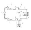
図1はアキュムレータ式冷凍サイクルの全体模式図である。
本実施例の冷凍装置は、例えば自動車用空調装置に適用されるもので、共沸点を有しない2種類の混合冷媒(例えば、HFC32とHFC134a)を使用するアキュムレータ式冷凍サイクル1と、この冷凍サイクル1の運転状態に応じてアキュムレータ2内に溜まる液冷媒を霧化させる霧化手段(後述する)とを備える。
冷凍サイクル1は、コンプレッサ3、オイルセパレータ4、コンデンサ5、膨張弁6、エバポレータ7、および前記アキュムレータ2の各機能部品より構成されて、図1に示すように、冷媒配管8により環状に接続されている。
【0009】
霧化手段は、図2に示すように、アキュムレータ2の底面(アキュムレータ2の内部でも良い)に取り付けられた加振器9と、この加振器9の作動を制御する制御装置10とから成る。
加振器9は、例えば超音波振動子を内蔵するもので、制御装置10を介して通電されると、超音波振動子が振動してアキュムレータ2内に溜まった液冷媒を霧化させることができる。
制御装置10は、冷凍サイクル1の運転状態(例えば、エバポレータ7で冷却された空気の温度)に応じて加振器9の通電制御を行なう。
【0010】
次に、本実施例の作動を説明する。
コンプレッサ3から吐出されたガス冷媒は、オイルセパレータ4を経てコンデンサ5に供給され、コンデンサ5の冷媒通路を流れる際に、コンデンサ5に送風される送風空気との熱交換によって凝縮液化される。一方、ガス冷媒とともにコンプレッサ3から吐出されたオイルは、オイルセパレータ4でガス冷媒と分離してオイルセパレータ4に溜まり、オイル戻し管11を通って再びコンプレッサ3に戻される。
コンデンサ5で液化した冷媒は、膨張弁6で減圧膨張されてエバポレータ7へ供給される。エバポレータ7に供給された低温低圧の冷媒は、エバポレータ7の冷媒通路を流れる際に、車室内へ送風される送風空気との熱交換によって蒸発する。
エバポレータ7で蒸発した冷媒(気液二相状態)は、アキュムレータ2で気液分離されて、液冷媒がアキュムレータ2に溜まり、ガス冷媒がコンプレッサ3に吸引される。
【0011】
ここで、冷凍サイクル1の冷媒として非共沸混合冷媒を使用した場合、冷凍サイクル1を循環する冷媒組成中に低沸点冷媒成分が多くなると、サイクル効率(成績係数COP)は低下するが、冷凍能力は向上する。一方、冷凍サイクル1を循環する冷媒組成中に高沸点冷媒成分が多くなると、冷凍能力は若干低下するが、サイクル効率は向上する(図3参照)。
そこで、クールダウン時(急速冷房時)等で大きな冷凍能力を必要とする場合には、冷凍サイクル1を循環する冷媒組成中の低沸点冷媒成分を多くし、定常運転時でサイクル効率を重視する場合には、冷凍サイクル1を循環する冷媒組成中の高沸点冷媒成分を多くすることが望ましい。
【0012】
これに対して、本実施例の冷凍サイクル1では、通常のサイクル運転時にアキュムレータ2に溜まる液冷媒が高沸点冷媒成分の多い組成となるため、必然的に冷凍サイクル1を循環する冷媒の組成は、低沸点冷媒成分の割合が多くなる(図3の組成▲1▼に示す状態)と言える。従って、冷凍能力の必要なクールダウン時には、加振器9をOFFしたままサイクル運転を行なうことにより、アキュムレータ2内に高沸点冷媒成分の多い液冷媒が溜まり、冷凍サイクル1を循環する冷媒を低沸点冷媒成分の多い組成とすることができる。一方、サイクル効率を重視する定常運転時には、加振器9をONしてアキュムレータ2内に溜まった液冷媒(高沸点冷媒成分の多い液冷媒)を霧化させることにより、加振器9をOFFしている時より高沸点冷媒成分の多い冷媒組成(図3の組成▲2▼に示す状態)とすることができる。なお、サイクル停止時には、加振器9をOFFしておくことにより、サイクル内の冷媒が高沸点冷媒を中心に主に低圧側に寝込む(溜まる)ので、サイクル内の冷媒組成は当初の状態に戻る。
【0013】
(本実施例の効果)
本実施例では、制御装置10により加振器9をONさせて、アキュムレータ2内に溜まった高沸点冷媒成分の多い液冷媒を霧化させて蒸発し易くすることにより、冷凍サイクル1を循環する冷媒組成の変動を抑制できる。これにより、冷媒の循環組成を封入時の冷媒組成に近づけることができるため、冷凍サイクル1の性能および信頼性の向上を図ることができる。
また、冷凍サイクル1の運転状態に応じて加振器9の作動を制御するだけで、冷凍能力の必要なクールダウン時には能力重視のサイクル運転を行なうことができ、定常運転時には効率重視のサイクル運転を行なうことができる。
【0014】
なお、クールダウン初期において、冷凍サイクル1を循環する冷媒が低沸点冷媒成分の多い組成であるために冷凍サイクル1の高圧が上昇し過ぎる場合には、加振器9をONさせて冷凍サイクル1を循環する冷媒を高沸点冷媒成分の多い組成とすることにより、冷凍サイクル1の高圧を低下させることもできる。
また、加振器9をOFFして能力重視のサイクル運転を行なう場合には、高沸点冷媒をより多くアキュムレータ2に溜めるために、低圧配管(膨張弁6の吐出側からコンプレッサ3の吸引側までの間を接続する冷媒配管8)等をアキュムレータ2の底部に接触させておく事も有効である。
【図面の簡単な説明】
【図1】冷凍サイクルの全体模式図である。
【図2】超音波振動子の取付け状態を示すアキュムレータの断面図である。
【図3】冷媒組成比と成績係数比および冷房能力比との関係を示すグラフである。
【符号の説明】
1 冷凍サイクル
2 アキュムレータ
9 加振器(霧化手段)
10 制御装置(霧化手段)[0001]
TECHNICAL FIELD OF THE INVENTION
The present invention relates to a refrigerating apparatus having an accumulator type refrigerating cycle using a non-azeotropic mixed refrigerant.
[0002]
[Prior art]
In recent years, a refrigeration cycle using two or three types of non-azeotropic mixed refrigerants containing no chlorine atom has been proposed in order to comply with the restriction on the use of CFCs (see Japanese Patent Application Laid-Open No. 62-94768).
[0003]
[Problems to be solved by the invention]
However, when a non-azeotropic mixed refrigerant is used, there is a problem that the refrigerant composition circulating in the refrigeration cycle and the sealing composition are different due to the characteristic that the liquid phase composition and the gas phase composition are different in the two-phase region. For example, when a non-azeotropic mixed refrigerant is used in an accumulator-type refrigeration cycle that accumulates excess refrigerant in an accumulator, a high-boiling refrigerant component is included in the composition of the liquid refrigerant that accumulates in the accumulator because the dryness of the refrigerant flowing into the accumulator is large. As a result, the operating pressure increases and the coefficient of performance (COP) decreases. Thus, in a refrigeration cycle using a non-azeotropic mixed refrigerant, it is difficult to ensure stable performance and reliability because the circulating composition greatly changes with respect to the enclosed composition of the mixed refrigerant.
The present invention has been made based on the above circumstances, and an object thereof is to improve the performance and reliability of a cycle by suppressing the fluctuation of the circulation composition with respect to the composition of the non-azeotropic refrigerant mixture. Is to provide.
[0004]
[Means for Solving the Problems]
The present invention has the following features to attain the object mentioned above.
(Claim 1)
An accumulator-type refrigeration cycle using a non-azeotropic mixed refrigerant, a vibrator attached to the accumulator and configured to atomize liquid refrigerant that has accumulated inside the accumulator, and according to an operation state of the refrigeration cycle. A control device for controlling the operation of the shaker, wherein the control device performs a cycle operation in a state where the operation of the shaker is stopped during a necessary cool down of the refrigerating capacity, During steady operation in which efficiency is emphasized, the vibrator is operated to atomize the liquid refrigerant (liquid refrigerant having a high boiling point refrigerant component) accumulated in the accumulator .
[0006]
【The invention's effect】
(Claim 1)
In the accumulator type refrigeration cycle, since the composition of the liquid refrigerant accumulated in the accumulator has a high boiling point refrigerant component, the liquid refrigerant retained in the accumulator is atomized by a vibrator to facilitate evaporation, thereby refrigeration. Fluctuation in the composition of the refrigerant circulating in the cycle can be suppressed. As a result, the performance and reliability of the refrigeration cycle can be improved.
Further, by controlling the operation of the vibrator by the control device, the composition of the refrigerant circulating in the refrigeration cycle can be changed according to the operation state of the refrigeration cycle. For example, when the vibrator is not operated, more high-boiling refrigerant stays in the accumulator than low-boiling refrigerant. As a result, since most of the refrigerant composition circulating in the refrigeration cycle is a low-boiling-point refrigerant, a cycle operation that emphasizes capacity can be performed. In addition, when the high-boiling refrigerant accumulated in the accumulator is atomized by operating the exciter, the composition of the refrigerant circulating in the refrigeration cycle becomes close to the composition at the time of the filling (the high-boiling refrigerant is higher than when the exciter is not operated). Since the number of components increases), it is possible to perform a cycle operation that emphasizes efficiency.
[0008]
【Example】
Next, an embodiment of the refrigeration apparatus of the present invention will be described with reference to the drawings.
FIG. 1 is an overall schematic diagram of an accumulator type refrigeration cycle.
The refrigerating apparatus of the present embodiment is applied to, for example, an air conditioner for an automobile, and includes an accumulator
The
[0009]
The atomizing means includes, as shown in FIG. 2, a
The
The
[0010]
Next, the operation of the present embodiment will be described.
The gas refrigerant discharged from the
The refrigerant liquefied by the
The refrigerant (gas-liquid two-phase state) evaporated by the
[0011]
Here, when a non-azeotropic mixed refrigerant is used as the refrigerant of the
Therefore, when a large refrigeration capacity is required at the time of cool down (rapid cooling) or the like, the low-boiling-point refrigerant component in the refrigerant composition circulating in the
[0012]
On the other hand, in the
[0013]
(Effects of the present embodiment)
In the present embodiment, the
In addition, by simply controlling the operation of the
[0014]
In the initial stage of the cool down, if the high pressure of the
Further, in the case of performing the cycle operation in which the performance is emphasized by turning off the
[Brief description of the drawings]
FIG. 1 is an overall schematic diagram of a refrigeration cycle.
FIG. 2 is a cross-sectional view of an accumulator showing an attached state of an ultrasonic transducer.
FIG. 3 is a graph showing a relationship between a refrigerant composition ratio, a coefficient of performance ratio, and a cooling capacity ratio.
[Explanation of symbols]
DESCRIPTION OF
10 control device (atomization means)
Claims (1)
前記アキュムレータに取り付けられ、前記アキュムレータの内部に滞留した液冷媒を霧化させるための加振器と、
前記冷凍サイクルの運転状態に応じて前記加振器の作動を制御する制御装置とを備える冷凍装置であって、
前記制御装置は、冷凍能力の必要なクールダウン時に、前記加振器の作動を停止した状態でサイクル運転を行ない、サイクル効率を重視する定常運転時に、前記加振器を作動させて前記アキュムレータ内に溜まった液冷媒(高沸点冷媒成分の多い液冷媒)を霧化させることを特徴とする冷凍装置。An accumulator-type refrigeration cycle using a non-azeotropic mixed refrigerant,
A vibrator attached to the accumulator, for atomizing the liquid refrigerant retained inside the accumulator ,
A control device for controlling the operation of the vibrator according to the operating state of the refrigeration cycle,
The control device performs a cycle operation in a state where the operation of the vibrator is stopped at the time of a cool-down required for the refrigeration capacity, and operates the vibrator during the steady operation in which cycle efficiency is emphasized, thereby operating the accumulator to perform the cycle operation. A refrigeration apparatus for atomizing liquid refrigerant (liquid refrigerant having a high boiling point refrigerant component) accumulated in a tank .
Priority Applications (1)
| Application Number | Priority Date | Filing Date | Title |
|---|---|---|---|
| JP19784795A JP3601122B2 (en) | 1995-08-03 | 1995-08-03 | Refrigeration equipment |
Applications Claiming Priority (1)
| Application Number | Priority Date | Filing Date | Title |
|---|---|---|---|
| JP19784795A JP3601122B2 (en) | 1995-08-03 | 1995-08-03 | Refrigeration equipment |
Publications (2)
| Publication Number | Publication Date |
|---|---|
| JPH0942806A JPH0942806A (en) | 1997-02-14 |
| JP3601122B2 true JP3601122B2 (en) | 2004-12-15 |
Family
ID=16381335
Family Applications (1)
| Application Number | Title | Priority Date | Filing Date |
|---|---|---|---|
| JP19784795A Expired - Fee Related JP3601122B2 (en) | 1995-08-03 | 1995-08-03 | Refrigeration equipment |
Country Status (1)
| Country | Link |
|---|---|
| JP (1) | JP3601122B2 (en) |
Families Citing this family (3)
| Publication number | Priority date | Publication date | Assignee | Title |
|---|---|---|---|---|
| JP3365273B2 (en) * | 1997-09-25 | 2003-01-08 | 株式会社デンソー | Refrigeration cycle |
| JP2022157187A (en) * | 2021-03-31 | 2022-10-14 | ダイキン工業株式会社 | Heat pump device |
| CN113237243A (en) * | 2021-04-26 | 2021-08-10 | 澳柯玛股份有限公司 | Refrigerating system and refrigerating method thereof |
-
1995
- 1995-08-03 JP JP19784795A patent/JP3601122B2/en not_active Expired - Fee Related
Also Published As
| Publication number | Publication date |
|---|---|
| JPH0942806A (en) | 1997-02-14 |
Similar Documents
| Publication | Publication Date | Title |
|---|---|---|
| US6523360B2 (en) | Cooling cycle and control method thereof | |
| JP3365273B2 (en) | Refrigeration cycle | |
| KR20040068869A (en) | Vapor-compression refrigerant cycle system with refrigeration cycle and rankine cycle | |
| JPH0886516A (en) | Refrigerating device | |
| EP1046869B1 (en) | Refrigeration/air conditioning system | |
| JP4400522B2 (en) | Ejector refrigeration cycle | |
| EP1394484A2 (en) | Method for operating a refrigerating cycle and a refrigerating cycle | |
| JP2000055488A (en) | Refrigerating device | |
| JPH10318614A (en) | Air conditioner | |
| US20110100038A1 (en) | Refrigerant Circuit And Method For Operating A Refrigerant Circuit | |
| US5752392A (en) | Air conditioner and heat exchanger therefor | |
| JPH10288411A (en) | Vapor pressure compression type refrigerating cycle | |
| JP3601122B2 (en) | Refrigeration equipment | |
| US5186011A (en) | Refrigerant cycling apparatus | |
| US20100024469A1 (en) | Refrigerating cycle apparatus | |
| JP2000064906A (en) | Engine-drive type heat pump cycle | |
| JP2000035251A (en) | Three layers separator in cooling cycle | |
| JPH07120082A (en) | Refrigerating cycle apparatus | |
| JPH0868567A (en) | Low-temperature generator | |
| JPH10318613A (en) | Freezing device | |
| JPH085201A (en) | Refrigerating cycle equipment | |
| JP2004177046A (en) | Binary refrigerating plant | |
| JP3448377B2 (en) | Refrigeration system using non-azeotropic refrigerant mixture | |
| JP3356601B2 (en) | Heat pump device using non-azeotropic refrigerant | |
| JPH07174421A (en) | Freezing device |
Legal Events
| Date | Code | Title | Description |
|---|---|---|---|
| A977 | Report on retrieval |
Free format text: JAPANESE INTERMEDIATE CODE: A971007 Effective date: 20040510 |
|
| A131 | Notification of reasons for refusal |
Free format text: JAPANESE INTERMEDIATE CODE: A131 Effective date: 20040518 |
|
| A521 | Written amendment |
Free format text: JAPANESE INTERMEDIATE CODE: A523 Effective date: 20040720 |
|
| TRDD | Decision of grant or rejection written | ||
| A01 | Written decision to grant a patent or to grant a registration (utility model) |
Free format text: JAPANESE INTERMEDIATE CODE: A01 Effective date: 20040831 |
|
| A61 | First payment of annual fees (during grant procedure) |
Free format text: JAPANESE INTERMEDIATE CODE: A61 Effective date: 20040913 |
|
| R150 | Certificate of patent or registration of utility model |
Free format text: JAPANESE INTERMEDIATE CODE: R150 |
|
| LAPS | Cancellation because of no payment of annual fees |