JP3600835B2 - Blood pump device - Google Patents
Blood pump device Download PDFInfo
- Publication number
- JP3600835B2 JP3600835B2 JP52136595A JP52136595A JP3600835B2 JP 3600835 B2 JP3600835 B2 JP 3600835B2 JP 52136595 A JP52136595 A JP 52136595A JP 52136595 A JP52136595 A JP 52136595A JP 3600835 B2 JP3600835 B2 JP 3600835B2
- Authority
- JP
- Japan
- Prior art keywords
- inflow
- bladder
- blood pump
- sac
- pump device
- Prior art date
- Legal status (The legal status is an assumption and is not a legal conclusion. Google has not performed a legal analysis and makes no representation as to the accuracy of the status listed.)
- Expired - Fee Related
Links
Images


Classifications
-
- A—HUMAN NECESSITIES
- A61—MEDICAL OR VETERINARY SCIENCE; HYGIENE
- A61M—DEVICES FOR INTRODUCING MEDIA INTO, OR ONTO, THE BODY; DEVICES FOR TRANSDUCING BODY MEDIA OR FOR TAKING MEDIA FROM THE BODY; DEVICES FOR PRODUCING OR ENDING SLEEP OR STUPOR
- A61M60/00—Blood pumps; Devices for mechanical circulatory actuation; Balloon pumps for circulatory assistance
- A61M60/80—Constructional details other than related to driving
- A61M60/855—Constructional details other than related to driving of implantable pumps or pumping devices
- A61M60/89—Valves
- A61M60/894—Passive valves, i.e. valves actuated by the blood
-
- A—HUMAN NECESSITIES
- A61—MEDICAL OR VETERINARY SCIENCE; HYGIENE
- A61M—DEVICES FOR INTRODUCING MEDIA INTO, OR ONTO, THE BODY; DEVICES FOR TRANSDUCING BODY MEDIA OR FOR TAKING MEDIA FROM THE BODY; DEVICES FOR PRODUCING OR ENDING SLEEP OR STUPOR
- A61M60/00—Blood pumps; Devices for mechanical circulatory actuation; Balloon pumps for circulatory assistance
- A61M60/10—Location thereof with respect to the patient's body
- A61M60/122—Implantable pumps or pumping devices, i.e. the blood being pumped inside the patient's body
- A61M60/165—Implantable pumps or pumping devices, i.e. the blood being pumped inside the patient's body implantable in, on, or around the heart
- A61M60/178—Implantable pumps or pumping devices, i.e. the blood being pumped inside the patient's body implantable in, on, or around the heart drawing blood from a ventricle and returning the blood to the arterial system via a cannula external to the ventricle, e.g. left or right ventricular assist devices
-
- A—HUMAN NECESSITIES
- A61—MEDICAL OR VETERINARY SCIENCE; HYGIENE
- A61M—DEVICES FOR INTRODUCING MEDIA INTO, OR ONTO, THE BODY; DEVICES FOR TRANSDUCING BODY MEDIA OR FOR TAKING MEDIA FROM THE BODY; DEVICES FOR PRODUCING OR ENDING SLEEP OR STUPOR
- A61M60/00—Blood pumps; Devices for mechanical circulatory actuation; Balloon pumps for circulatory assistance
- A61M60/40—Details relating to driving
- A61M60/424—Details relating to driving for positive displacement blood pumps
- A61M60/427—Details relating to driving for positive displacement blood pumps the force acting on the blood contacting member being hydraulic or pneumatic
-
- A—HUMAN NECESSITIES
- A61—MEDICAL OR VETERINARY SCIENCE; HYGIENE
- A61M—DEVICES FOR INTRODUCING MEDIA INTO, OR ONTO, THE BODY; DEVICES FOR TRANSDUCING BODY MEDIA OR FOR TAKING MEDIA FROM THE BODY; DEVICES FOR PRODUCING OR ENDING SLEEP OR STUPOR
- A61M60/00—Blood pumps; Devices for mechanical circulatory actuation; Balloon pumps for circulatory assistance
- A61M60/40—Details relating to driving
- A61M60/424—Details relating to driving for positive displacement blood pumps
- A61M60/438—Details relating to driving for positive displacement blood pumps the force acting on the blood contacting member being mechanical
- A61M60/449—Details relating to driving for positive displacement blood pumps the force acting on the blood contacting member being mechanical generated by a solenoid
-
- A—HUMAN NECESSITIES
- A61—MEDICAL OR VETERINARY SCIENCE; HYGIENE
- A61M—DEVICES FOR INTRODUCING MEDIA INTO, OR ONTO, THE BODY; DEVICES FOR TRANSDUCING BODY MEDIA OR FOR TAKING MEDIA FROM THE BODY; DEVICES FOR PRODUCING OR ENDING SLEEP OR STUPOR
- A61M60/00—Blood pumps; Devices for mechanical circulatory actuation; Balloon pumps for circulatory assistance
- A61M60/10—Location thereof with respect to the patient's body
- A61M60/122—Implantable pumps or pumping devices, i.e. the blood being pumped inside the patient's body
- A61M60/126—Implantable pumps or pumping devices, i.e. the blood being pumped inside the patient's body implantable via, into, inside, in line, branching on, or around a blood vessel
- A61M60/148—Implantable pumps or pumping devices, i.e. the blood being pumped inside the patient's body implantable via, into, inside, in line, branching on, or around a blood vessel in line with a blood vessel using resection or like techniques, e.g. permanent endovascular heart assist devices
-
- Y—GENERAL TAGGING OF NEW TECHNOLOGICAL DEVELOPMENTS; GENERAL TAGGING OF CROSS-SECTIONAL TECHNOLOGIES SPANNING OVER SEVERAL SECTIONS OF THE IPC; TECHNICAL SUBJECTS COVERED BY FORMER USPC CROSS-REFERENCE ART COLLECTIONS [XRACs] AND DIGESTS
- Y10—TECHNICAL SUBJECTS COVERED BY FORMER USPC
- Y10S—TECHNICAL SUBJECTS COVERED BY FORMER USPC CROSS-REFERENCE ART COLLECTIONS [XRACs] AND DIGESTS
- Y10S128/00—Surgery
- Y10S128/03—Heart-lung
Landscapes
- Health & Medical Sciences (AREA)
- Heart & Thoracic Surgery (AREA)
- Engineering & Computer Science (AREA)
- Cardiology (AREA)
- Biomedical Technology (AREA)
- Anesthesiology (AREA)
- Mechanical Engineering (AREA)
- Hematology (AREA)
- Life Sciences & Earth Sciences (AREA)
- Animal Behavior & Ethology (AREA)
- General Health & Medical Sciences (AREA)
- Public Health (AREA)
- Veterinary Medicine (AREA)
- External Artificial Organs (AREA)
Description
〔発明の属する技術分野〕
本発明は人体内に埋めこんで使用する血液ポンプに関し、より詳しくは左心室援助用として好適な血液ポンプに関する。
〔発明の背景〕
人工心臓の開発へむけて様々な血液ポンプの形態及びシステムが作られている。本発明は、変形自在な袋嚢(サック:sac)を用いてポンプ動作を行う、いわゆる「袋嚢型」のポンプに関する。袋嚢を変形させて内容積を小さくすると袋嚢の中身はワンウェイバルブを通して吐出される。袋嚢が変形前にもどって内容積が大きくなると、ワンウェイバルブを通って液体が袋嚢に流れ込み、次のストロークに備える。このタイプは人間や動物の心臓の動作に類似したものとなる。
上述のタイプのポンプは様々な手段によって駆動することができる。あるものは空気圧で動作させ、他のものでは流体を膨張・収縮させている。さらにソレノイドやモータ等の電気的手段によって駆動するものもある。
しかしながら、血液ポンプ装置を人体内に埋めこむに際しては、いずれのタイプにおいても共通する問題点が多数指摘されている。まずシステムは体内に埋めこむことができる大きさでなければならず、体内のどこか隙間に収容できる形状でなければならない。システムへの流入側と吐出側の結合については、システムと体内の血流との接続が容易で、所望のポンプ動作可能なものでなければならない。また流入側と吐出側の接続部は簡易で信頼性の高い構造でなければならない。さらにシステムは長期にわたる連続使用に対して高い信頼性を要求される。そしてシステムにおける流れは血栓が形成したり、血が固まったりしないような特性をもたなければならない。
従来技術による血液ポンプの装置及びシステムは、いくつかの点では有望であるけれども、大きな欠点があってその実用化は妨げられていた。このような欠点の中には、ダイヤフラムのハウジングにつなぎ目や切れ目があったため、しばしば血栓を発生させていたことがある。血栓を発生させる他の要因としては、内側の形状が不適切であったり、材質の選択が不適切であったり、袋嚢を変形させたときにシワが出来たりすることがある。
USP No.4557673(出願人はカリフォルニア州オークランドのNovacor Medical Corporation)では、従来製造されていた袋嚢変形型のシステムにおける多くの欠点を実質的に解決することができる袋嚢変形型血液ポンプを開示している。詳しくは後述するが、かかるポンプ装置の優れた特徴は主に、(1)ポンプ室の形状が丸型であること、(2)流入口と吐出口を接線方向に配していること、(3)ポンプの袋嚢が変形に対する復元力を備えていることによっている。これらの要因の結果、ポンプのチャンバ内への流入の工程において(特にストローク体積の小さいときでも)、渦巻き状の流れ、即ち「洗い流す」流れのパターンが急激に発生し、血栓の発生する可能性を最小限に抑えている。
図1乃至3では前記特許に係る血液ポンプ装置を示しており、ポンプ10は符号12で示されるチャンバ部材を備えている。部材12は変形可能な袋嚢14を有し、その側壁16は環状に形成され、対面する丸型の変位可能な壁面18,20(図2参照)は弾力のある回旋状の(湾曲)壁部22,24を介して前記側壁に結合されている。液体は袋嚢の丸室26に延設された流入口28から流れこみ、同様に延設された吐出口30より圧力をかけられて吐出される。
上述の血液ポンプにおいては、流入口28と吐出口30はそれぞれの長さ全体にわたりほぼ円形断面となっており、流入および吐出の流れの方向が袋嚢の環状の側壁に対して接線方向に配されている。流入口28及び吐出口30には流入バルブ32のような弁部材が備えられ、流れを弁動作で一方にむける、ポンプに必須の動作をする。図2に示す如く、流入バルブ32はチャンバ部材12における丸室26の近くに配置され、渦巻き流によって丸室26と流入バルブ32が効果的に洗い流されるようになっている。
対面する押圧板34,36は、ポンプのアクチュエータ38に連結され、丸室26の液体を吐出させる。アクチュエータ38は連結部材を介して機械的に各押圧板34,36へ連結され、例えば押圧板34はアーム40によってアクチュエータに連結されている。
なお図1について補足すれば、ポンプ10のハウジング42は、堅固なハウジングリング44と堅固なシェル46とで部材12の中央部を包み込んでいる。シェル46には袋嚢14の流入口28及び吐出口30を収容する通りみちが形成されている。
本発明の目的は、前記特許に比べて多くの優れた特徴を備えた袋嚢変形型の血液ポンプ装置を提供し、従来知られていなかった多くのユニークな特徴によってシステムの作動特性を向上させることにある。
本発明の他の目的は、流入管と吐出管を着脱自在とし、その中に袋嚢への流入と吐出の流れをコントロールするための弁を備えたポンプ装置を提供することにある。
本発明のさらに他の目的は、弁を有する管部とポンプとの結合部に介在する生体適合物質の段差移行部の数を最小にすることができるポンプ装置を提供することである。
本発明の他の目的は、変形自在な袋嚢の流入口に先細部を設けてポンプ動作中の流れを円形の袋嚢の側壁に導き一様な流れを生じさせて、袋嚢の内面に血栓が形成される可能性を最小限にすることができるポンプ装置を提供することである。
本発明のさらなる目的は、流入圧及び吐出圧が小さいときでもすみやかに袋嚢内に一様な流れを生成させることができるポンプ装置を提供することにある。
本発明の他の目的は、ストロークの体積の広い範囲に適合できるポンプ装置を提供することである。
〔発明の概要〕
血液ポンプ装置には、可撓性がありかつ弾性力のある素材でできた継ぎ目なし(シームレス)構造の変形自在な袋嚢が備えられ、これは(i)ほぼ平らな円形の壁面を対面させて、これらを実質的に断面が半円状の側壁を環状に配して結合し、(ii)流入口及び吐出口を有している。流入口には先細部を非対象に設け、流入の流れを袋嚢の環状の側壁に向けて、袋嚢内になめらかな渦流を発生させて、血栓の発生を最小に抑える。袋嚢の両側には対面する一対の押圧板が配設され、各押圧板は袋嚢の前記平らな壁面と密着し、平らな壁面を相互に変位させて袋嚢を変形させる。変位手段によって2枚の押圧板は周期的に互いに接離する。またポンプ装置には流入管及び吐出管が着脱自在に設けられ、流入及び吐出の流れをコントロールするための弁を備えている。流入管及び吐出管にはポンプに取付けるための結合部材がシール手段とともに備えられている。
【図面の簡単な説明】
本発明のさらなる特徴と効果は添付図面に示した好ましい実施形態についての以下の説明によって明らかになるであろう。なお図面において対応する要素には同様な符号を付している。
図1は、従来技術による血液ポンプ装置を示す平面図である。
図2は、図1の2−2線による断面図である。
図3は、従来技術による血液ポンプの袋嚢を示す斜視図である。
図4は、本発明による血液ポンプ装置の平面図である。
図5は、図4の5−5線による断面図である。
図5aは、図4の5a−5a線における断面図である。
図6は、本発明による血液ポンプ装置の袋嚢とポンプハウジングの変形していない状態における外形を示す斜視図である。
図7は、本発明による血液ポンプ装置の流入口の先細部について一部を破断して示す斜視図である。
図8は、図4の8−8線による断面図である。
図9は、図4の9−9線による断面図である。
図9aは、図4の9a−9a線による断面図である。
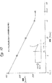
図10は、本発明における流入口の先細部の断面積の減少具合を示すもので、長さ方向の位置と断面積との関係を示すグラフである。
図11は、血液ポンプの袋嚢の流入口の形態のバリエーションを示す模式図である。
〔発明の詳細な説明〕
本発明によれば、血液ポンプ装置は、略半円断面の環状壁によって結合された、変形前の形態でほぼ平らな円形の一対の対向壁と、流入及び排出手段とを備えた変形自在な袋嚢と、平らな壁を互いに向かって移動させて袋嚢を変形させるための一対の押圧板と、弁を内部に備えた着脱自在な流入及び吐出管とを有する。
詳しくは後述するが、本発明の流入口には先細部を非対象に設けており、流入の流れを袋嚢の環状の側壁に向ける。ポンプの動作中には流入口の先細部により袋嚢内に最適な渦巻流が発生し、袋嚢内での血栓の発生の可能性を最小に抑える。
図4は本発明の血液ポンプ装置であって、ポンプ100はチャンバ部材110を備えている。この部材はポンプ100の他の部品を取り除いた状態で図6に示している。チャンバ部材110の構造とユニークな特徴については後述するが、この部材は変形自在な袋嚢111と、その環状の側壁112と、対面して配置された一対の変位可能な丸い壁部113,114と、これらを結合する柔軟な丸まった側壁部分117,119とからなっている。これらによって袋嚢の丸室115は内容積が変化自在に構成されている(図5参照)。液体は流入口121から丸室115に流れこみ、圧力をかけられて吐出口123から吐出される。図4に示す如く、変形自在な袋嚢111はこれと同一形状で堅固な材料で形成されたハウジング116内に収容されている。ハウジング116には開口118,120が形成され、それぞれには袋嚢111の流入口121及び吐出口123が挿通している。実施形態のさらなる応用としては、ポンプ部材110を水密構造のハウジングに完全に収め、ハウジングに生体適合性のコーティングを施すようにしてもよい。
血液ポンプ100には一対の押圧板134,136が対面して設けられ、平らな壁面113,114と密着している。好ましい実施形態において押圧板134,136は変位手段で操作されて内方へ変位可能であり、このとき平らな壁面113,114もストロークの「終点」位置113',114'に向かって変位して、丸室115から液体を吐出させる。ポンプ100の構造としては、一方の押圧板だけを他方に向けて変位させて壁面を動かして丸室の容積を減少させることもできることは、当業者に理解されるであろう。
変位手段は連結部材を介して機械的に各押圧板134,136へ連結され、例えば押圧板134はアーム140によって変位手段に連結されている。変位手段は、向かい合う連結部材を同時に内側へ動かして所定のポンプ動作をさせるように働く。
本発明の変位手段としては、空気圧動作によるもの,液体の膨張・収縮によるもの,モータやソレノイド型の電気によるアクチュエータを採用することができるが、好ましくは、ソレノイドアクチュエータ132を用いると効率が高く、電気的に制御して脈動を得ることができる。特にソレノイドのアーマチュアと血液ポンプの機械的駆動を分離して、バネ部材を介装してエネルギーを貯めるようにすれば、効率は高く、慣性は小さく、心臓の鼓動速度における応答性が高まる。またソレノイド駆動は構造が単純なので長期間の信頼性にも優れている。図5及び図6に示す如く、流入口122,吐出口124は、それぞれ流入口121,吐出口123を介して丸室115に連通している。流入口121及び吐出口123は、弓状の方向にほぼ同じ大きさに設けられ、袋嚢111の当該部分はそれぞれ流入ハウジング118および吐出ハウジング120に通されている。この構造の利点は、流入口121及び吐出口123の流体の通る面積が袋嚢111の安定した動かない側壁部に形成されているため、ポンプ動作に伴って流入口121及び吐出口123の形状が変化しないことである。
本発明の袋嚢111は、血液との親和性があり、可撓性がありかつ弾性力のある素材による継ぎ目なし(シームレス)構造でできている。本発明においては、袋嚢の材質は血液ポンプ用として用いられるいかなる材質をも適用することができる。袋嚢111の材質は変動する応力と圧力のもとで長期にわたって機械的強度を維持できるものでなければならない。また血液に対する有害性が低く化学的な安定性が長期維持できなければならない。さらに袋嚢の材質は(i)強度が高く、(ii)繰り返し変形に耐え、(iii)殺菌消毒に耐え、(iv)製造容易でなければならない。
当業者にはわかるだろうが、様々な生体適合性の材質の袋嚢が本発明の範囲内において可能である。好ましい実施形態では、袋嚢の材質としてリニアセグメントなポリウレタンを用いている。
袋嚢111の内面は、血栓の形成を防止できなければならない。本発明では血液に接触する面は、好ましくは、なめらかなポリウレタンの耐血栓性の面となっている。しかし、当業者に理解されるように、様々な種類の血液と接触する面及びコーティングを本発明の範囲内で適用することができる。
前述のように、流入口122及び吐出口124には、袋嚢111から一体的に延設された流入口121及び吐出口123を備えている。好ましい実施形態では、流入口121,吐出口123は袋嚢111の環状の側壁112のなす円に対して接するように配置される。これにより血液の流れを接線方向に向けて袋嚢111へ流入及び吐出させることで流れの乱れを最小限とし、血栓が発生する可能性を抑えるためである。
当業者はわかるだろうが、流入口121及び吐出口123の内径の寸法は重要である。すでに述べたように本発明の第1の目的は袋嚢111内においてストローク体積の大小に関わらず、また流入吐出圧が低いときであっても、すみやかに一様な渦流の洗いながす流れを発生させることにある。この目的を達成するには多くの競合する要因を満足させなければならない。
例えば、流入口の(又はそのノド部の)開口断面積と流入圧が与えられたとき、ストローク体積が大きくなるほど丸室115内には良好な流れが発生する。ストローク体積が小さいときには、時間当たりの流入量は少なく、流入速度は小さい。流入口のノド部の断面積を減らしていくと、あるところまでは、ストローク体積が小さいときの流入速度をはやめることができ、丸室115内の流れを活発にすることができる。しかしそれを越えるとノド部の面積を減らすにつれて流入抵抗が大きくなり、時間当たりの流入量は減り、速度も小さくなる。流入量と速度が小さくなると流れの発生も弱くなり、血栓が発生する可能性が高くなる。吐出口の面積については、ノド部を小さくすることで流入工程における流れをより活発に、一様にすることができる。逆に吐出口を大きくすると流れが不連続になり、丸室115内の渦流が乱されてしまう。しかし吐出口の面積を小さくすることは、吐出抵抗の増加と後述する袋嚢の製造の2点から限界がある。袋嚢の製造方法としては、袋嚢111の内周形状と同一の外形をもったアルミニウム製の心金を精密に機械加工,研磨加工し、全体をコーティングして用いるのが好ましい。袋嚢の対向する環状の変形する部分113,114は円周方向に均一であり、かかる変形部分を成形する心金の表面も精密に機械加工され研磨されコーティングされて極めて滑らかになっている。袋嚢111を形成するには繰り返し所定のポリマー溶液に心金を浸し、回しながら赤外線ランプで乾燥させる。
袋嚢111を心金から外すには、流入口121又は吐出口123のいずれかから心金を引き抜かなければならない。このため心金を引き抜く側の入り口の形状と最小寸法は、心金の大きさと形状の影響を直接受ける。
詳しくは後述するが、本発明の血液ポンプは、この対立するパラメータに対して最適な解を与える。流入口の形状は、最高の流れの発生を得られるとともに広い範囲のストローク体積で流入抵抗が生理学的に受容できるように最適化される。吐出口の形状は、丸室115内の流れが一様で活発になるように最適化される。さらに吐出口の形状は、上述のディップ−キャスト製造の際に心金から袋嚢111を取り外す便宜もよい。
次に図4乃至9を参照して流入口121の詳細について説明する。まず図4及び図7に示す如く、本発明の好ましい実施形態では、流入口121には円錐状の先細部125が非対称に設けられ、血液の流入を袋嚢111の環状の側壁112に向けるようになっている(矢印A参照)。非対称な先細部にほぼ楕円形のノド部(後述)を設けることで丸室115内の渦流を最適にすることができることが明らかになった。先細部125は十分に均一であり、ここに血栓は発生しない。
図8に示す如く、非対称な先細部125の一端は実質的に円形な流入口133となっており、他端は実質的に楕円形のノド部126となっている。好ましい実施形態ではノド部の外壁135は流入口の外壁128とまっすぐにつながっており、流入する流れを袋嚢111の環状の側壁112のなす円に対して接するように導く(図9参照)。図8及び図9aに示すように、ノド部126の中心軸129は袋嚢111の円形の断面の中央の平面に位置するようになっている。前述のように非対称な先細部125は袋嚢111内に一様で好ましくは渦状の流れを発生させ血栓の形成を最小限に抑える。また先細部125は流入口121と丸室115の接続部131において流れが拡がるのも抑止する。
本発明の好ましい実施形態では、ほぼ円形の流入口121(及び先細部133)の直径はおよそ18から33mm、好ましくは20から22mmになっている。図4及び図8に示す如く、先細部125は初めのうちはほぼ円形な部分210に向かって収束し(図9参照)、この直径は12から17mm、好ましくは14から16mmになっている。先細部125が丸いチャンバ部材110に結合される部分では、先細部125は楕円形断面に変化していく。先細部125の楕円形のノド部126の高さ(9−9面による。符号230参照)は、10から15mmで、好ましくは11から13mmである。
先細部125の長さは一般的におよそ15から23mmで、好ましくは17から22mmである。先細部125と流入口121の内方の壁面127とのなす角は、およそ15゜から30゜で、好ましくは17゜から28゜であり、さらには26゜が好ましい。
本発明では先細部125の断面積の減少は、その長さに対して線型的(リニア)でも非線型(ノンリニア)でも、あるいはその組み合わせでもよい。好ましい実施形態では以下に述べるように先細部125の単位長さ当たりの断面積の減少の具合は初めはリニアであるが最後はノンリニアに変化している。
図10のグラフは、本発明における断面積の減少の様子を示している。前記実施形態では、先細部125の最初の断面積(Xjと示す)は約380mm2となっている。先細部125の10.16mm進んだ箇所では断面積は約245mm2である。17.8mmで(Xlと示す)、断面積は最小の180mm2となる。先細部125の断面積はほぼ全域にわたってリニアに変化しているが、ノド部126の近くでノンリニアになってチャンバ部材110に接続している。この部分では断面の形状が実質的に円形から楕円形へと変化している(図8参照)。本発明では吐出口123も丸室115からなめらかに移行している。好ましい実施形態では、吐出口の直径は18から33mmで、好ましくは22から23mmである。
上述の流入口121及び吐出口123の流れの可視化によって調べてみると、ポンプの拡張(即ち流入)の際には、一様な渦流が発生して袋嚢111の内面全体を洗い流している。渦状の流れは拡張期に極めてすみやかに発生し、収縮期の初めまで持続する。
上述の流入口121及び吐出口123は、ストローク体積がおよそ20から70mlの袋嚢変形型ポンプ装置に適用されるものであるが、当業者は前記寸法関係を比例的に増減させれば本発明の範囲内で大小のストローク体積の血液ポンプ装置が得られることを理解するだろう。
本発明のポンプ装置では、流入バルブ及び吐出バルブを用いてポンプ100での一方向への流れを得ている。好ましい実施形態では、着脱自在な流入管160及び吐出管161の中に流入バルブ150及び吐出バルブ151を外付けしている(図4参照)。別の実施形態としては、図示しないが、流入バルブ及び吐出バルブを流入口121及び吐出口123のなかに配置してもよい。
着脱自在な管161,161は、外方にステント(stented)された、3枚の湾曲した薄いバルブを有するポリエステルの管を備えており、ポリエステルの表面には水を浸透しないコーティングが施されている(図示せず)。管160,161は生体適合性の外装165に収められて保護されている。管160,161には血液の流れを乱すことなく相手方の部材に結合するための新規な手段が備えられている。また結合部についても血液と接触する部材の数や生体適合材料の変化を少なくしている。バルブ付きの管についての詳細は、係属中の出願、No.08/192,894、発明の名称"Ventricular Assist Device with Valved Blood Conduit and Method of Making"、出願日1994年2月7日を参照されたい。図4及び図5aに示す如く、ポンプの流入及び吐出ハウジング118,120には管160,161を着脱自在に接続するための接続手段が備えられている。本発明における接続手段としては、流入口121及び吐出口123とバルブ付き管160,161とを堅固で高い信頼性で結合できればいかなる手段でもよい。本発明では、流入口121及び吐出口123とバルブ付き管160,161との接合部からの漏れを抑止するためのシール手段を備えている。好ましい実施形態ではシール手段は少なくとも2つの同軸シール181,182を備えている。同軸シール181,182について以下に詳しく説明する。
図5aにおいて、結合部材にはハウジングリング180が備えられ、適当な手段でポンプのバルクヘッド188に締付けられている。リング180は好ましくはチタンや強固な繊維複合体などの軽量で耐蝕性の素材でできている。
次にシール181,182の詳細を図5aを参照して説明する。シール181は袋嚢の前記流入口及び吐出口の終端部を折返した新規な構造をもつ。より詳しくは、シール181は袋嚢の一部をハウジングリング180の先端に被せるように折り返し、適当な接着手段によってリング180の内周190及び外周192に固着している。さらに袋嚢側の部材は後述する面シール182によって機械的にリング180に締付けられ、流入口121及び吐出口123とバルブ付き管160,161との結合の信頼性を一層向上させている。
図5aに示す如く、袋嚢を折返したことで端面にほぼ半円形のシール面183が形成される。また袋嚢を折返す構造により段差の発生を最小とし、従来技術で生じていた流れの乱れを防止する。
さらに面シール182によってポンプと管160,161との接続面でのシール性能を向上させている。面シール182はシール181と略同軸で、リング180とシール181に対して適当な手段で締付けられる。より詳しくは面シール182はハウジングリング180内に納められ、保持力を働かせるとともに袋嚢側の部材をリング180の外周192に締付ける。本発明では、面シールのシール面184がシール面183とほぼ平行な平面に配置されている。
さらに、図5aに示すように、結合手段にはバルブ付き管160,161をポンプ100に有効に締付けるための手段が備えられている。好ましい実施形態では、ハウジングリング180にはフランジ185が延設され、そのネジ部186が管側のネジ部167と螺合するようになっている。実施形態の応用としては(図示せず)、結合手段にキー溝などの安全手段を設けて流入側及び吐出側のバルブ付き管160,161の適確な配置を確保してもよい。
上記結合手段について補足すれば、ポンプのバルクヘッド188はポンプのハウジング116にしっかり固定され、シール181,182及びリング180を包み込んでいる。バルクヘッド188は軽量かつ堅固な生体適合素材、好ましくはPEEK(polyetheretherketone)で形成するのがよい。
当業者には理解されるように、本発明における流入側及び吐出側の結合手段は介在する生体物質と段差移行部を最小に抑えることができる。さらに結合手段はポンプの袋嚢(ポリウレタン)とバルブ付き管(ポリエステル)とを直接接続し、血液と金属との接触箇所は存在しない。
〔実施例〕
流れの可視化による一連の実験を行って血液ポンプの流入口及び吐出口の最適な形状と大きさを決定した。実験はストローク体積が20から70mlの血液ポンプ装置について行った。
図11は流れの可視化の実験で用いた血液ポンプの袋嚢を示す模式図である。袋嚢200は丸い本体部201と流入口202,吐出口203とこれらの円形の開口204,205とを備えている。
以下の実施例によって本発明のすばらしい特性が明らかになるであろう。ただし実施例は例証の目的のためのものであって、いかなる意味でもクレームの範囲を限定するものではない。
(実施例1)
各実施例において、流入口204及び吐出口205は断面がほぼ円形になっている。流入口202のまっすぐな脚部の直径(D2)は20mmである。吐出口203の直径(D1)は19.7mmで断面はほぼ円形である。
流入口(202)と袋嚢の本体(201)の結合部は鋭角(212)とした。吐出口(203)と本体(201)との結合部(213)の半径(R)は8.4mmである。
この形状では袋嚢の内部での全体的な流れは極めて弱かった。
(実施例2)
実施例2の吐出口の形状と大きさは実施例1と同じになっている。流入口(202)には本体部との結合部において直線状の先細部(208)を設けている。傾斜の角度(θ)は約17.5゜である。
流入口(204)の初めの直径(D2)は20mmであるが、略楕円形のノド部(206)へと変化する。ノド部(206)の幅(W)は符号230で示すB−B断面において16.5mmで、高さ(H)は11.4から11.7mmである。この形状ではポンプ内の流れの特性はかなり良好であった。
(実施例3)
実施例3でも吐出口(203)は実施例1及び2と同様である。流入口の直径(D2)は18mmとし、楕円に変化したノド部(206)の幅(W)は13.7mm、高さ(H)は11.4から11.7mmである。傾斜角度(θ)も小さめの16゜とした。
ノド部の幅と傾斜角度を小さくしたところ、ポンプ内での流れの様子は非常に良好であった。
(実施例4)
実施例4でも吐出口(203)の形状と大きさは実施例1乃至3と同じとした。まっすぐな傾斜部の傾斜角度(θ)は25゜とし、流入口の直径(D2)は22mmでノド部の幅(W)は12.7mmとした。
この形状でもポンプ内には非常に良好な流れが得られた。しかしこの形状は抵抗が大きすぎるようであった。
(実施例5)
実施例5では流入口と吐出口の形状及び大きさは実施例4と同じであり、傾斜角度(θ)を22゜、ノド部の幅(W)を14.5mmとした点が異なる。この形状でも流れの状態は非常に良好であった。
(実施例6)
実施例6では流入口と吐出口の形状及び大きさは実施例5と同じであるが、傾斜部を円弧状(210)に形成した。
円弧状の傾斜部でもまっすぐな傾斜部と同様にポンプ内に良好な流れがみられたが、このような流入口の形状は抵抗が大きいことも見出された。
(実施例7)
実施例7では流入口(202)と吐出口(203)の形状は実施例5と同じとした。但し、流入側に傾斜部(208)を設け、前記寸法公差に収めるために、吐出口の直径(D2)を大きくしなければ製造段階で袋嚢200を心金から引き抜けないことが判明した。見積もりによれば「引き抜き」可能な最小の直径はおよそ25mmである。新たな心金を製作し、袋嚢の流入口(202)の傾斜角度(θ)を26゜とし、吐出口(203)の直径を25mmとした。吐出口と本体の結合部(213)の半径(R)は9.7mmとした。
この形状でも流れの状態は良好ないし非常に良好であった。しかし、吐出口を大きくすると本体のチャンバ(201)を大きくしたような効果があり、結果的にチャンバ内での流速が全体的に遅くなることがわかった。チャンバ(201)内での渦流の形成も実施例5に比べて遅くなった。
(実施例8)
実施例8では流入口の形状と大きさは実施例7と同様にした。吐出口の形状も実施例7とほぼ同様であるが、異なるのは吐出口の直径(D1)を24mmに小さくし、本体の結合部を鋭角(213)に形成することとした。
この寸法でも流れの形状は非常に良好であったが、実施例7ほど良好ではなかった。
(実施例9)
実施例9では流入口の形状は実施例8と同様とした。吐出口の形状は実施例8と同様であるが、直径(D1)を23mmにした。
吐出口の直径を1mm小さくすることで、ポンプ全体にすばらしい流れが得られることがわかった。この実験により吐出口の最大の直径は23mmであることが決定された。
(実施例10)
実施例10では流入口の形状と大きさは実施例9と同様にした。吐出口の直径(D1)は更に小さく22mmとし、本体との結合部(213)の半径(R)は6.4mmとした。6.4mmの半径とすることで、製造工程で心金から袋嚢を引き抜くのを容易にすることができる。
以上の寸法によってポンプ内での最適な流れの状態が得られた。
上記実験の結果をまとめて表1に示す。
以上のように本発明によれば、人間若しくは動物の体内に埋め込んで使用する、とりわけ左心室援助用として好適な血液ポンプ装置を提供することができる。本システムの流入管及び吐出管は着脱自在でありバルブを内蔵している。流入口の新規なる形状によって内面の形状変化はスムーズなものとなる。さらに血栓が発生する継ぎ目はほとんどなく、ポンプ内全体を洗い流すように滑らかな渦流を発生させることができる。
以上の説明と添付図面から、当業者は本発明を様々に変形応用することができるであろうが、かかる変形は添付した請求の範囲に収まるものである。

The present invention relates to a blood pump used by being implanted in a human body, and more particularly to a blood pump suitable for left ventricular assist.
[Background of the Invention]
Various blood pump configurations and systems have been created for the development of artificial hearts. TECHNICAL FIELD The present invention relates to a so-called “bag-sac-type” pump that performs a pump operation using a deformable bag (sac). When the bladder is deformed to reduce its internal volume, the contents of the bladder are discharged through a one-way valve. When the bladder returns to its original shape and the internal volume increases, the liquid flows into the bladder through the one-way valve to prepare for the next stroke. This type mimics the behavior of the human or animal heart.
Pumps of the type described above can be driven by various means. Some operate pneumatically and others expand and contract fluids. Some are driven by electric means such as a solenoid or a motor.
However, when embedding a blood pump device in a human body, many problems common to all types have been pointed out. First, the system must be large enough to be implanted in the body, and shaped to fit into any gap in the body. The connection between the inflow side and the discharge side to the system should be such that the connection between the system and the blood flow in the body is easy and the desired pump operation is possible. The connection between the inflow side and the discharge side must have a simple and highly reliable structure. Furthermore, the system is required to have high reliability for long-term continuous use. And the flow in the system must have such properties that thrombus does not form or blood clots.
Although promising in some respects, prior art blood pump devices and systems have had significant drawbacks that have prevented their practical application. Among the drawbacks is that seams and cuts in the diaphragm housing often result in thrombus formation. Other factors that cause thrombus generation include improper inner shape, improper material selection, and wrinkling when deforming the sac.
USP No. 4557673 (to the applicant of Novacor Medical Corporation, Oakland, Calif.) Discloses a bladder-modified blood pump that can substantially overcome many of the drawbacks of the conventionally manufactured sacs-modified system. are doing. As will be described in detail later, the excellent features of such a pump device are mainly (1) that the shape of the pump chamber is round, (2) that the inlet and the outlet are arranged tangentially, 3) It is because the bag of the pump has a restoring force against deformation. As a result of these factors, during the process of pumping into the chamber (especially even at small stroke volumes), a spiral or "washing out" flow pattern is rapidly generated, which can lead to thrombus formation. Is kept to a minimum.
1 to 3 show a blood pump device according to the above patent, and a
In the above-described blood pump, the
The facing
1, the
SUMMARY OF THE INVENTION It is an object of the present invention to provide a bag-sampling type blood pump device having many superior features as compared with the above-mentioned patents, and to improve the operating characteristics of the system by a number of unique features which have not been known before. It is in.
Another object of the present invention is to provide a pump device in which an inflow pipe and a discharge pipe are detachable, and which has a valve for controlling the flow of inflow and discharge into the sac.
It is still another object of the present invention to provide a pump device capable of minimizing the number of step transition portions of a biocompatible substance interposed in a connection portion between a pipe having a valve and a pump.
It is another object of the present invention to provide a taper at the inlet of the deformable bladder to direct the flow during pumping to the side wall of the circular bladder to create a uniform flow on the inner surface of the bladder. An object of the present invention is to provide a pump device that can minimize the possibility that a thrombus is formed.
It is a further object of the present invention to provide a pump device that can quickly generate a uniform flow in a bladder even when the inflow pressure and the discharge pressure are small.
Another object of the invention is to provide a pump device that can be adapted to a wide range of stroke volumes.
[Summary of the Invention]
The blood pump device is provided with a deformable bladder having a seamless (seamless) structure made of a flexible and resilient material, which (i) has a substantially flat circular wall face to face. These are joined by arranging annular side walls substantially semicircular in cross section, and (ii) having an inlet and an outlet. The inlet has an asymmetrical taper, directing the inflow stream to the annular side wall of the sac and creating a smooth vortex in the sac to minimize thrombus formation. A pair of opposing pressing plates are disposed on both sides of the sac, and each pressing plate is in close contact with the flat wall surface of the sac and displaces the flat wall surfaces to deform the sac. The two pressing plates are periodically moved toward and away from each other by the displacement means. The pump device is provided with an inflow pipe and a discharge pipe detachably, and is provided with a valve for controlling the flow of inflow and discharge. The inflow pipe and the discharge pipe are provided with coupling members for attaching to the pump together with sealing means.
[Brief description of the drawings]
Further features and advantages of the present invention will become apparent from the following description of preferred embodiments illustrated in the accompanying drawings. In the drawings, corresponding elements are denoted by similar reference numerals.
FIG. 1 is a plan view showing a blood pump device according to the related art.
FIG. 2 is a sectional view taken along line 2-2 of FIG.
FIG. 3 is a perspective view showing a bag of a conventional blood pump.
FIG. 4 is a plan view of the blood pump device according to the present invention.
FIG. 5 is a sectional view taken along line 5-5 in FIG.
FIG. 5A is a sectional view taken along line 5a-5a in FIG.
FIG. 6 is a perspective view showing an outer shape of the bag bag and the pump housing of the blood pump device according to the present invention in an undeformed state.
FIG. 7 is a partially cutaway perspective view showing the tapered portion of the inflow port of the blood pump device according to the present invention.
FIG. 8 is a sectional view taken along line 8-8 in FIG.
FIG. 9 is a sectional view taken along line 9-9 in FIG.
FIG. 9A is a sectional view taken along line 9a-9a in FIG.
FIG. 10 is a graph showing how the cross-sectional area of the tapered portion of the inflow port is reduced in the present invention, and is a graph showing the relationship between the position in the longitudinal direction and the cross-sectional area.
FIG. 11 is a schematic diagram showing a variation of the form of the inlet of the bag of the blood pump.
[Detailed description of the invention]
In accordance with the present invention, a blood pump device is provided with a pair of substantially flat circular opposing walls in a pre-deformed configuration, joined by annular walls of substantially semicircular cross-section, and an inflow and outflow means. It has a bladder, a pair of pressure plates for moving the flat walls toward each other to deform the bladder, and a removable inlet and outlet pipe with a valve inside.
As will be described in greater detail below, the inflow port of the present invention has an asymmetrical taper to direct the flow of inflow to the annular sidewall of the bladder. During operation of the pump, the taper of the inlet creates optimal swirl flow within the bladder, minimizing the possibility of thrombus formation within the bladder.
FIG. 4 shows a blood pump device according to the present invention, in which a
The displacement means is mechanically connected to each of the
As the displacement means of the present invention, a means by pneumatic operation, a means by expansion and contraction of liquid, a motor or an actuator by solenoid type electricity can be adopted, but it is preferable to use a
The bladder 111 of the present invention has a seamless (seamless) structure made of a material which has affinity for blood, is flexible and has elasticity. In the present invention, any material used for a blood pump can be applied to the material of the bag. The material of the bladder 111 must be capable of maintaining mechanical strength for a long period of time under fluctuating stress and pressure. In addition, chemical stability must be maintained for a long time with low toxicity to blood. Further, the material of the sacs should be (i) high in strength, (ii) resistant to repeated deformation, (iii) resistant to sterilization and disinfection, and (iv) easy to manufacture.
As those skilled in the art will appreciate, sacs of various biocompatible materials are possible within the scope of the present invention. In a preferred embodiment, linear segment polyurethane is used as the material of the bladder.
The inner surface of the sac 111 must be capable of preventing thrombus formation. In the present invention, the surface that comes into contact with blood is preferably a smooth polyurethane thrombus-resistant surface. However, as will be appreciated by those skilled in the art, various types of blood contacting surfaces and coatings can be applied within the scope of the present invention.
As described above, the
As will be appreciated by those skilled in the art, the dimensions of the inner diameter of
For example, when the cross-sectional area of the opening of the inflow port (or its throat portion) and the inflow pressure are given, the larger the stroke volume, the better the flow is generated in the
In order to remove the sac 111 from the mandrel, the mandrel must be withdrawn from either the
As will be described in more detail below, the blood pump of the present invention provides an optimal solution to this conflicting parameter. The shape of the inlet is optimized so as to obtain the highest flow generation and that the inflow resistance is physiologically acceptable over a wide range of stroke volumes. The shape of the discharge port is optimized so that the flow in the
Next, details of the
As shown in FIG. 8, one end of the
In a preferred embodiment of the present invention, the diameter of the substantially circular inlet 121 (and the taper 133) is approximately 18 to 33 mm, preferably 20 to 22 mm. As shown in FIGS. 4 and 8, the
The length of the
In the present invention, the reduction of the cross-sectional area of the
The graph of FIG. 10 shows how the cross-sectional area decreases in the present invention. In the above embodiment, the initial cross-sectional area (X j Is about 380mm Two It has become. The cross-sectional area is approximately 245 mm at the point advanced 10.16 mm of the
According to the visualization of the flow through the
The above-mentioned
In the pump device of the present invention, one-way flow is obtained by the
Removable tubes 161,161 comprise outwardly stented polyester tubing with three curved thin valves, the surface of which is coated with a water-impermeable coating ( Not shown). The
In FIG. 5a, the coupling member is provided with a
Next, details of the
As shown in FIG. 5a, a substantially
Further, the sealing performance at the connection surface between the pump and the
Further, as shown in FIG. 5a, the coupling means is provided with means for effectively clamping the
Supplementing the above coupling means, the
As will be appreciated by those skilled in the art, the coupling means on the inflow and discharge sides in the present invention can minimize the intervening biological material and the step transition. Furthermore, the coupling means directly connects the bag of the pump (polyurethane) and the tube with the valve (polyester), and there is no point of contact between the blood and the metal.
〔Example〕
A series of experiments with flow visualization were performed to determine the optimal shape and size of the blood pump inlet and outlet. The experiment was performed on a blood pump device having a stroke volume of 20 to 70 ml.
FIG. 11 is a schematic view showing a bladder of a blood pump used in a flow visualization experiment. The
The following examples will demonstrate the great properties of the present invention. However, the examples are for illustrative purposes and do not limit the scope of the claims in any way.
(Example 1)
In each embodiment, the
The junction between the inflow port (202) and the bag body (201) was at an acute angle (212). The radius (R) of the joint (213) between the discharge port (203) and the main body (201) is 8.4 mm.
In this configuration, the overall flow inside the bladder was very weak.
(Example 2)
The shape and size of the discharge port in the second embodiment are the same as those in the first embodiment. The inflow port (202) is provided with a linear tapered portion (208) at the connection with the main body. The angle of inclination (θ) is about 17.5 °.
Initial diameter of inlet (204) (D Two ) Is 20 mm, but changes to a substantially elliptical gutter (206). The width (W) of the gutter portion (206) is 16.5 mm in the BB cross section indicated by
(Example 3)
The discharge port (203) in the third embodiment is the same as in the first and second embodiments. Inlet diameter (D Two ) Is 18 mm, the width (W) and the height (H) of the elliptical gutter part (206) are 13.7 mm and 11.4 to 11.7 mm. The inclination angle (θ) was also set to a small value of 16 °.
When the width of the throat portion and the inclination angle were reduced, the flow state in the pump was very good.
(Example 4)
In Example 4, the shape and size of the discharge port (203) were the same as those in Examples 1 to 3. The angle of inclination (θ) of the straight slope is 25 °, and the diameter of the inlet (D Two ) Was 22 mm and the width (W) of the throat portion was 12.7 mm.
Even with this configuration, a very good flow was obtained in the pump. However, this shape appeared to have too much resistance.
(Example 5)
In the fifth embodiment, the shapes and sizes of the inflow port and the discharge port are the same as those in the fourth embodiment, except that the inclination angle (θ) is 22 ° and the width (W) of the throat portion is 14.5 mm. Even in this shape, the flow condition was very good.
(Example 6)
In the sixth embodiment, the shapes and sizes of the inflow port and the discharge port are the same as those of the fifth embodiment, but the inclined portion is formed in an arc shape (210).
Good flow was seen in the pump as well as the straight ramps in the arc-shaped ramps, but it was also found that such an inlet configuration had high resistance.
(Example 7)
In the seventh embodiment, the shapes of the inflow port (202) and the discharge port (203) are the same as in the fifth embodiment. However, a slope (208) is provided on the inflow side, and the diameter (D Two It has been found that the
Even in this shape, the flow condition was good or very good. However, it has been found that increasing the discharge port has the effect of increasing the size of the chamber (201) of the main body, and as a result, the flow velocity in the chamber is reduced as a whole. The formation of the vortex in the chamber (201) was also slower than in Example 5.
(Example 8)
In Example 8, the shape and size of the inflow port were the same as in Example 7. The shape of the discharge port is almost the same as that of the seventh embodiment except that the diameter of the discharge port (D 1 ) Was reduced to 24 mm, and the joint of the main body was formed at an acute angle (213).
At this dimension the flow shape was very good but not as good as in Example 7.
(Example 9)
In the ninth embodiment, the shape of the inflow port was the same as in the eighth embodiment. The shape of the discharge port is the same as in Example 8, but the diameter (D 1 ) Was 23 mm.
It has been found that reducing the diameter of the discharge port by 1 mm can provide excellent flow throughout the pump. From this experiment, it was determined that the maximum diameter of the discharge port was 23 mm.
(Example 10)
In Example 10, the shape and size of the inflow port were the same as in Example 9. Outlet diameter (D 1 ) Is even smaller, 22 mm, and the radius (R) of the joint (213) with the main body is 6.4 mm. With a radius of 6.4 mm, the bag can be easily pulled out of the mandrel during the manufacturing process.
With the above dimensions, an optimal flow condition in the pump was obtained.
Table 1 summarizes the results of the above experiments.
As described above, according to the present invention, it is possible to provide a blood pump device which is used by being implanted in a human or animal body, and particularly suitable for assisting a left ventricle. The inflow pipe and the discharge pipe of this system are detachable and have built-in valves. The new shape of the inlet makes the shape change of the inner surface smooth. Further, there is almost no seam where a thrombus is generated, and a smooth vortex can be generated so as to flush the entire inside of the pump.
From the above description and accompanying drawings, those skilled in the art will be able to apply various modifications to the present invention, and such modifications fall within the scope of the appended claims.
Claims (5)
前記流入口には円錐状の先細部が非対称に設けられ、流入する流れを前記袋嚢の前記環状の側壁に向けて、前記袋嚢内に円滑な流れを生ぜしめ、
袋嚢の両側には対面する一対の押圧板が配設され、各押圧板は袋嚢の前記平らな壁面と密着し、少なくとも一方の前記平らな壁面を他方に対して相互に変位させて袋嚢を変形させ、
流入する流れをコントロールするバルブを有する流入管が前記流入口に着脱自在に接続され、
前記流入管を前記流入口に接続する第1の結合手段が備えられるとともに、前記第1の結合手段には前記流入管と前記流入口との結合部をシールする第1のシール手段が備えられ、
吐出する流れをコントロールするバルブを有する吐出管が前記吐出口に着脱自在に接続され、
前記吐出管を前記吐出口に接続する第2の結合手段が備えられるとともに、前記第2の結合手段には前記吐出管と前記吐出口との結合部をシールする第2のシール手段が備えられたことを特徴とする血液ポンプ装置。A blood pump device used by being implanted in a human body, comprising a deformable sac, wherein the shape of the sac before deformation is such that a pair of substantially flat circular walls face in parallel, and these are substantially The side walls having a semi-circular cross section are arranged in an annular shape and connected to each other, and the bag is made of a seamless structure made of a flexible and resilient material. An inlet and an outlet are provided, and these are provided on the side wall so as to be in contact with a circle formed by the annular side wall of the sac,
The inlet is provided with a conical taper asymmetrically, directing the incoming flow toward the annular side wall of the bladder, producing a smooth flow in the bladder,
A pair of pressing plates facing each other are disposed on both sides of the sac, and each pressing plate is in close contact with the flat wall surface of the sac and displaces at least one of the flat wall surfaces with respect to the other. Deform the sac,
An inflow pipe having a valve for controlling the inflow is detachably connected to the inflow port,
First coupling means for connecting the inflow pipe to the inflow port is provided, and the first coupling means is provided with first sealing means for sealing a coupling portion between the inflow pipe and the inflow port. ,
A discharge pipe having a valve for controlling a flow to be discharged is detachably connected to the discharge port,
A second connecting means for connecting the discharge pipe to the discharge port is provided, and the second connecting means is provided with a second sealing means for sealing a connecting portion between the discharge pipe and the discharge port. Blood pump device characterized by the above-mentioned.
Applications Claiming Priority (3)
| Application Number | Priority Date | Filing Date | Title |
|---|---|---|---|
| US08/194,481 | 1994-02-10 | ||
| US08/194,481 US5511958A (en) | 1994-02-10 | 1994-02-10 | Blood pump system |
| PCT/US1995/001724 WO1995021638A1 (en) | 1994-02-10 | 1995-02-09 | Blood pump system |
Publications (2)
| Publication Number | Publication Date |
|---|---|
| JPH09508833A JPH09508833A (en) | 1997-09-09 |
| JP3600835B2 true JP3600835B2 (en) | 2004-12-15 |
Family
ID=22717764
Family Applications (1)
| Application Number | Title | Priority Date | Filing Date |
|---|---|---|---|
| JP52136595A Expired - Fee Related JP3600835B2 (en) | 1994-02-10 | 1995-02-09 | Blood pump device |
Country Status (6)
| Country | Link |
|---|---|
| US (2) | US5511958A (en) |
| EP (1) | EP0743863B1 (en) |
| JP (1) | JP3600835B2 (en) |
| CA (1) | CA2182665C (en) |
| DE (1) | DE69531822T2 (en) |
| WO (1) | WO1995021638A1 (en) |
Families Citing this family (63)
| Publication number | Priority date | Publication date | Assignee | Title |
|---|---|---|---|---|
| US8409846B2 (en) | 1997-09-23 | 2013-04-02 | The United States Of America As Represented By The Department Of Veteran Affairs | Compositions, methods and devices for maintaining an organ |
| US6100082A (en) * | 1997-09-23 | 2000-08-08 | Hassanein; Waleed H. | Perfusion apparatus and method including chemical compositions for maintaining an organ |
| US6889082B2 (en) * | 1997-10-09 | 2005-05-03 | Orqis Medical Corporation | Implantable heart assist system and method of applying same |
| US6387037B1 (en) | 1997-10-09 | 2002-05-14 | Orqis Medical Corporation | Implantable heart assist system and method of applying same |
| US6610004B2 (en) | 1997-10-09 | 2003-08-26 | Orqis Medical Corporation | Implantable heart assist system and method of applying same |
| US6390969B1 (en) | 1997-10-09 | 2002-05-21 | Orqis Medical Corporation | Implantable heart assist system and method of applying same |
| UA56262C2 (en) | 1997-10-09 | 2003-05-15 | Орквіс Медікел Корпорейшн | Extracardiac pumping system for supplementing blood circulation |
| US5980448A (en) * | 1998-01-28 | 1999-11-09 | Vascor, Inc. | Single chamber blood pump |
| US6050987A (en) * | 1998-09-21 | 2000-04-18 | The United States Of America As Represented By The Administrator Of The National Aeronautics And Space Administration | Tubular coupling |
| AU2188700A (en) | 1998-12-15 | 2000-07-03 | Corvascular, Inc. | Intravascular cardiac assist device and method |
| CA2355324A1 (en) | 1998-12-18 | 2000-06-29 | Berlin Heart Ag | Pulsatile pump |
| US6146325A (en) * | 1999-06-03 | 2000-11-14 | Arrow International, Inc. | Ventricular assist device |
| US6342071B1 (en) | 1999-07-08 | 2002-01-29 | Benjamin David Pless | Ambulatory blood pump |
| US6346071B1 (en) * | 1999-07-16 | 2002-02-12 | World Heart Corporation | Inflow conduit assembly for a ventricular assist device |
| US6770024B1 (en) * | 2000-03-28 | 2004-08-03 | Stony Brook Surgical Innovations, Inc. | Implantable counterpulsation cardiac assist device |
| US20020173695A1 (en) * | 2001-05-16 | 2002-11-21 | Mikhail Skliar | Physiologically-based control system and method for using the same |
| US6579223B2 (en) | 2001-08-13 | 2003-06-17 | Arthur Palmer | Blood pump |
| WO2004002552A1 (en) * | 2002-06-26 | 2004-01-08 | Micromed Technology, Inc. | Method and system for physiologic control of a blood pump |
| CN101816811A (en) * | 2002-01-07 | 2010-09-01 | 麦克罗美德技术公司 | Pump system |
| US7396327B2 (en) * | 2002-01-07 | 2008-07-08 | Micromed Technology, Inc. | Blood pump system and method of operation |
| US20050159639A1 (en) * | 2002-05-15 | 2005-07-21 | Mikhail Skliar | Physiologically based control system and method for using the same |
| US7258679B2 (en) * | 2002-08-09 | 2007-08-21 | Vascor, Inc. | Inflow conduit for ventricular assist device |
| WO2004052172A2 (en) | 2002-12-06 | 2004-06-24 | World Heart Corporation | Miniature, pulsatile implantable ventricular assist devices and methods of controlling ventricular assist devices |
| US8128127B2 (en) * | 2003-09-25 | 2012-03-06 | Tronox Llc | Changing fluid flow direction |
| US20050085683A1 (en) * | 2003-10-15 | 2005-04-21 | Bolling Steven F. | Implantable heart assist system and method of applying same |
| JP2007510258A (en) * | 2003-10-31 | 2007-04-19 | ベントラコー リミテッド | Plasma immersion ion implantation using conductive mesh |
| US20050131385A1 (en) * | 2003-12-12 | 2005-06-16 | Bolling Steven F. | Cannulae for selectively enhancing blood flow |
| US20050277870A1 (en) * | 2004-06-10 | 2005-12-15 | Robert Pecor | Cannula having reduced flow resistance |
| US7445592B2 (en) * | 2004-06-10 | 2008-11-04 | Orqis Medical Corporation | Cannulae having reduced flow resistance |
| US12010987B2 (en) | 2004-10-07 | 2024-06-18 | Transmedics, Inc. | Systems and methods for ex-vivo organ care and for using lactate as an indication of donor organ status |
| US9301519B2 (en) * | 2004-10-07 | 2016-04-05 | Transmedics, Inc. | Systems and methods for ex-vivo organ care |
| CA3178010A1 (en) * | 2004-10-07 | 2006-04-20 | Transmedics, Inc. | Systems and methods for ex-vivo organ care |
| US8304181B2 (en) | 2004-10-07 | 2012-11-06 | Transmedics, Inc. | Method for ex-vivo organ care and for using lactate as an indication of donor organ status |
| WO2006047620A2 (en) * | 2004-10-25 | 2006-05-04 | Arthur Palmer | Method for making a blood pump and pumping blood |
| US20060184199A1 (en) * | 2005-02-14 | 2006-08-17 | O'leary Shawn | Apparatus and methods for reducing bleeding from a cannulation site |
| US20060224110A1 (en) * | 2005-03-17 | 2006-10-05 | Scott Michael J | Methods for minimally invasive vascular access |
| US9078428B2 (en) * | 2005-06-28 | 2015-07-14 | Transmedics, Inc. | Systems, methods, compositions and solutions for perfusing an organ |
| US8535934B2 (en) * | 2006-04-19 | 2013-09-17 | Transmedics, Inc. | Systems and methods for ex vivo organ care |
| US9457179B2 (en) | 2007-03-20 | 2016-10-04 | Transmedics, Inc. | Systems for monitoring and applying electrical currents in an organ perfusion system |
| US20090076531A1 (en) * | 2007-09-18 | 2009-03-19 | Richardson Charles L | Method and apparatus for bypass graft |
| US9247728B2 (en) * | 2008-01-31 | 2016-02-02 | Transmedics, Inc. | Systems and methods for ex vivo lung care |
| US20100160939A1 (en) * | 2008-12-19 | 2010-06-24 | St. Jude Medical, Inc. | Systems, apparatuses, and methods for cardiovascular cutting devices and valves |
| US8728012B2 (en) * | 2008-12-19 | 2014-05-20 | St. Jude Medical, Inc. | Apparatus and method for measuring blood vessels |
| US9566146B2 (en) * | 2008-12-19 | 2017-02-14 | St. Jude Medical, Inc. | Cardiovascular valve and valve housing apparatuses and systems |
| US8905961B2 (en) * | 2008-12-19 | 2014-12-09 | St. Jude Medical, Inc. | Systems, apparatuses, and methods for cardiovascular conduits and connectors |
| US9060507B2 (en) | 2010-09-01 | 2015-06-23 | Perfusion Fluid Technologies Inc | Perfusion solution |
| ES2913104T3 (en) | 2011-04-14 | 2022-05-31 | Transmedics Inc | Organ care solution for ex-vivo machine perfusion of donor lungs |
| US20130055887A1 (en) * | 2011-09-02 | 2013-03-07 | Allied Healthcare Products Inc. | Multiple valve head compressor apparatus |
| CN113287600B (en) | 2014-06-02 | 2022-08-19 | 特兰斯迈迪茨公司 | Perfusion circuit and system for perfusion of isolated liver and system for preservation thereof |
| CA2970117A1 (en) | 2014-12-12 | 2016-06-16 | Darren FREED | Apparatus and method for organ perfusion |
| JP6934005B2 (en) | 2015-09-09 | 2021-09-08 | トランスメディクス,インコーポレイテッド | Aortic Cannula for Exobibo Organ Management System |
| US10377097B2 (en) * | 2016-06-20 | 2019-08-13 | Terumo Cardiovascular Systems Corporation | Centrifugal pumps for medical uses |
| GB2555435A (en) * | 2016-10-27 | 2018-05-02 | Calon Cardio Tech Ltd | Cardiac pump |
| DE102018201030A1 (en) | 2018-01-24 | 2019-07-25 | Kardion Gmbh | Magnetic coupling element with magnetic bearing function |
| DE102018206724A1 (en) | 2018-05-02 | 2019-11-07 | Kardion Gmbh | Energy transmission system and method for wireless energy transmission |
| DE102018206725A1 (en) | 2018-05-02 | 2019-11-07 | Kardion Gmbh | Receiving unit, transmitting unit, energy transmission system and method for wireless energy transmission |
| DE102018206754A1 (en) | 2018-05-02 | 2019-11-07 | Kardion Gmbh | Method and device for determining the temperature at a surface and use of the method |
| DE102018207611A1 (en) | 2018-05-16 | 2019-11-21 | Kardion Gmbh | Rotor bearing system |
| DE102018208541A1 (en) | 2018-05-30 | 2019-12-05 | Kardion Gmbh | Axial pump for a cardiac assist system and method of making an axial pump for a cardiac assist system |
| DE102018211327A1 (en) | 2018-07-10 | 2020-01-16 | Kardion Gmbh | Impeller for an implantable vascular support system |
| DE102018212153A1 (en) | 2018-07-20 | 2020-01-23 | Kardion Gmbh | Inlet line for a pump unit of a cardiac support system, cardiac support system and method for producing an inlet line for a pump unit of a cardiac support system |
| DE102020102474A1 (en) | 2020-01-31 | 2021-08-05 | Kardion Gmbh | Pump for conveying a fluid and method for manufacturing a pump |
| US11699551B2 (en) | 2020-11-05 | 2023-07-11 | Kardion Gmbh | Device for inductive energy transmission in a human body and use of the device |
Family Cites Families (9)
| Publication number | Priority date | Publication date | Assignee | Title |
|---|---|---|---|---|
| GB449272A (en) * | 1935-02-16 | 1936-06-24 | Briggs & Co Ltd S | Improved construction of union for pipes or tubes |
| US3011803A (en) * | 1958-01-31 | 1961-12-05 | Dumont Aviat Associates | Swivel conduit joint |
| US4167046A (en) * | 1977-12-12 | 1979-09-11 | Andros, Inc. | Blood pumping device |
| JPS6022944B2 (en) * | 1980-11-10 | 1985-06-05 | 日本ゼオン株式会社 | Blood pump device |
| US4557673A (en) * | 1982-12-03 | 1985-12-10 | Novacor Medical Corporation | Implantable pump |
| JPH0411715Y2 (en) * | 1985-08-30 | 1992-03-24 | ||
| JPH0622911B2 (en) * | 1987-10-23 | 1994-03-30 | 日本ゼオン株式会社 | Method for manufacturing spherical molded body |
| US4902291A (en) * | 1989-01-31 | 1990-02-20 | University Of Utah Research Foundation | Collapsible artificial ventricle and pumping shell |
| US5171207A (en) * | 1991-04-03 | 1992-12-15 | Whalen Biomedical, Inc. | Apparatus and method of use for pulsatile blood flow |
-
1994
- 1994-02-10 US US08/194,481 patent/US5511958A/en not_active Expired - Lifetime
-
1995
- 1995-02-09 EP EP95911677A patent/EP0743863B1/en not_active Expired - Lifetime
- 1995-02-09 WO PCT/US1995/001724 patent/WO1995021638A1/en active IP Right Grant
- 1995-02-09 DE DE69531822T patent/DE69531822T2/en not_active Expired - Fee Related
- 1995-02-09 JP JP52136595A patent/JP3600835B2/en not_active Expired - Fee Related
- 1995-02-09 CA CA002182665A patent/CA2182665C/en not_active Expired - Fee Related
- 1995-06-07 US US08/473,220 patent/US5599173A/en not_active Expired - Lifetime
Also Published As
| Publication number | Publication date |
|---|---|
| DE69531822T2 (en) | 2004-10-07 |
| CA2182665C (en) | 2003-04-15 |
| US5599173A (en) | 1997-02-04 |
| WO1995021638A1 (en) | 1995-08-17 |
| DE69531822D1 (en) | 2003-10-30 |
| EP0743863B1 (en) | 2003-09-24 |
| EP0743863A1 (en) | 1996-11-27 |
| JPH09508833A (en) | 1997-09-09 |
| CA2182665A1 (en) | 1995-08-17 |
| US5511958A (en) | 1996-04-30 |
Similar Documents
| Publication | Publication Date | Title |
|---|---|---|
| JP3600835B2 (en) | Blood pump device | |
| US6001056A (en) | Smooth ventricular assist device conduit | |
| US12064611B2 (en) | Intravascular blood pump with intake filter | |
| EP3972661B1 (en) | Blood pumps | |
| AU2010249562B2 (en) | Multi-lumen cannula | |
| US7998190B2 (en) | Intravascular miniature stent pump | |
| US8556958B2 (en) | Recoverable valve stent | |
| CN102083481B (en) | Cannula tip for use with a VAD | |
| JP5449164B2 (en) | Device having an impeller | |
| JPH11239617A (en) | Improved cannula device | |
| JPH0411715Y2 (en) | ||
| JP2005528184A (en) | Method for determining the helix angle of a helical structure of a conduit | |
| JPH08215312A (en) | Balloon catheter | |
| CN220110268U (en) | Pump head of conduit pump | |
| CN219001739U (en) | Intervention type blood pump | |
| US20020198436A1 (en) | Circulation assist method and device utilizing balloon of IABP system and blood stream control valve therefor | |
| JPH1052489A (en) | Cannula and supplemental circulation device | |
| WO2003041782A1 (en) | Aortic cannula | |
| WO2024037119A1 (en) | Interventional blood pump with outlet flow guide structure | |
| CN221601049U (en) | Fluid tube, blood pumping catheter assembly and heart blood flow auxiliary system | |
| CN117398600A (en) | Blood pump | |
| CN209679131U (en) | A kind of snakelike curling peritoneum dialysis catheter of the more fold-types of shape for hat lantern ring reducing conduit offset | |
| US20230414921A1 (en) | Flexible outflow cannula with shaped outlets | |
| CN117398598A (en) | Blood pump | |
| CN116328174A (en) | Catheter pump and filter assembly method thereof |
Legal Events
| Date | Code | Title | Description |
|---|---|---|---|
| A01 | Written decision to grant a patent or to grant a registration (utility model) |
Free format text: JAPANESE INTERMEDIATE CODE: A01 Effective date: 20040518 |
|
| A61 | First payment of annual fees (during grant procedure) |
Free format text: JAPANESE INTERMEDIATE CODE: A61 Effective date: 20040617 |
|
| A711 | Notification of change in applicant |
Free format text: JAPANESE INTERMEDIATE CODE: A711 Effective date: 20040617 |
|
| R150 | Certificate of patent or registration of utility model |
Free format text: JAPANESE INTERMEDIATE CODE: R150 |
|
| FPAY | Renewal fee payment (event date is renewal date of database) |
Free format text: PAYMENT UNTIL: 20081001 Year of fee payment: 4 |
|
| FPAY | Renewal fee payment (event date is renewal date of database) |
Free format text: PAYMENT UNTIL: 20091001 Year of fee payment: 5 |
|
| LAPS | Cancellation because of no payment of annual fees |