JP3600144B2 - Performance evaluation method, maintenance method, and performance management system for plasma processing apparatus, and plasma processing apparatus and performance confirmation system for plasma processing apparatus - Google Patents
Performance evaluation method, maintenance method, and performance management system for plasma processing apparatus, and plasma processing apparatus and performance confirmation system for plasma processing apparatus Download PDFInfo
- Publication number
- JP3600144B2 JP3600144B2 JP2000289489A JP2000289489A JP3600144B2 JP 3600144 B2 JP3600144 B2 JP 3600144B2 JP 2000289489 A JP2000289489 A JP 2000289489A JP 2000289489 A JP2000289489 A JP 2000289489A JP 3600144 B2 JP3600144 B2 JP 3600144B2
- Authority
- JP
- Japan
- Prior art keywords
- plasma processing
- frequency power
- frequency
- processing apparatus
- plasma
- Prior art date
- Legal status (The legal status is an assumption and is not a legal conclusion. Google has not performed a legal analysis and makes no representation as to the accuracy of the status listed.)
- Expired - Lifetime
Links
Images


Landscapes
- Plasma Technology (AREA)
- Chemical Vapour Deposition (AREA)
- Drying Of Semiconductors (AREA)
Description
【0001】
【発明の属する技術分野】
本発明は、プラズマ処理装置の性能評価方法、保守方法、及び性能管理システム、並びにプラズマ処理装置に係り、特に、プラズマ処理装置が所望の性能を維持し続けることを、継続的に担保することに用いて好適な技術に関する。
【0002】
【従来の技術】
CVD( chemical vapor deposition)、スパッタリング、ドライエッチング、アッシング等のプラズマ処理をおこなうプラズマ処理装置の一例としては、従来から、図22に示すような、いわゆる2周波励起タイプのものが知られている。
図22に示すプラズマ処理装置は、高周波電源1とプラズマ励起電極4との間に整合回路2Aが介在されている。整合回路2Aはこれら高周波電源1とプラズマ励起電極4との間のインピーダンスの整合を得るための回路として設けられている。
【0003】
高周波電源1からの高周波電力は整合回路2Aを通して給電板3によりプラズマ励起電極4へ供給される。この整合回路2Aは導電体からなるハウジングにより形成されるマッチングボックス2内に収納されており、プラズマ励起電極4および給電板3は、導体からなるシャーシ21によって覆われている。
プラズマ励起電極(カソード電極)4の下側には凸部4aが設けられるとともに、このプラズマ励起電極(カソード電極)4の下には、多数の孔7が形成されているシャワープレート5が凸部4aに接して設けられている。これらプラズマ励起電極4とシャワープレート5との間には空間6が形成されている。この空間6にはガス導入管17が接続されており、導体からなるガス導入管17の途中には絶縁体17aが挿入されてプラズマ励起電極14側とガス供給源側とが絶縁されている。
【0004】
ガス導入管17から導入されたガスは、シャワープレート5の孔7を介してチャンバ壁10により形成されたチャンバ室60内に供給される。なお、符号9はチャンバ壁10とプラズマ励起電極(カソード電極)4とを絶縁する絶縁体である。また、排気系の図示は省略してある。
一方、チャンバ室60内には基板16を載置しプラズマ励起電極ともなるウエハサセプタ(サセプタ電極)8が設けられておりその周囲にはサセプタシールド12が設けられている。
【0005】
サセプタシールド12はサセプタ電極8を受けるシールド支持板12Aと、このシールド支持板12Aの中央部に垂下形成された筒型の支持筒12Bとからなり、支持筒12Bはチャンバ底部10Aを貫通して設けられるとともに、この支持筒12Bの下端部とチャンバ底部10Aとがベローズ11により密閉接続されている。これら、ウエハサセプタ8およびサセプタシールド12は、これらの隙間がシャフト13の周囲に設けられた電気絶縁物からなる絶縁手段12Cによって真空絶縁されるとともに電気的にも絶縁されている。また、ウエハサセプタ8およびサセプタシールド12は、ベローズ11により上下動可能となっており、プラズマ励起電極4,8間の距離の調整ができる。
ウエハサセプタ8には、シャフト13およびマッチングボックス14内に収納された整合回路を介して第2の高周波電源15が接続されている。なお、チャンバ壁10とサセプタシールド12とは直流的に同電位となっている。
【0006】
図23に従来のプラズマ処理装置の他の例を示す。図22に示すプラズマ処理装置とは異なり、図23に示すプラズマ処理装置は1周波励起タイプのプラズマ処理装置である。すなわち、カソード電極4にのみ高周波電力を供給しており、サセプタ電極8は接地されている。図22で示される高周波電源15とマッチングボックス14がない。また、サセプタ電極8とチャンバ壁10とは直流的に同電位となっている。
【0007】
上記のプラズマ処理装置においては、一般的に13.56MHz程度の周波数の電力を投入して、両電極4,8の間でプラズマを生成し、このプラズマにより、CVD( chemical vapor deposition)、スパッタリング、ドライエッチング、アッシング等のプラズマ処理をおこなうものである。
【0008】
そして、このようなプラズマ処理装置の動作確認および、動作の評価方法としては、例えば、以下のように実際に成膜等の処理をおこない、この被成膜特性を評価するというような方法でおこなっていた。
(1)堆積速度と膜面内均一性
▲1▼基板上にプラズマCVDにより所望の膜を成膜する。
▲2▼レジストのパターニングをおこなう。
▲3▼膜をドライエッチングする。
▲4▼アッシングによりレジストを剥離する。
▲5▼膜の膜厚段差を触針式段差計により計測する。
▲6▼成膜時間と膜厚から堆積速度を算出する。
▲7▼膜面内均一性は、6インチ基板面内において16ポイントで測定する。
(2)BHFエッチングレート
上記(1)▲1▼〜▲2▼と同様にレジストマスクをパターニングする。
▲3▼BHF液に1分間基板を浸漬する。
▲4▼純水洗浄後乾燥し、レジストをH2SO4+H2O2 で剥離する。
▲5▼上記(1)▲5▼と同様段差を計測する。
▲6▼浸漬時間と段差からエッチング速度を算出する。
(3)絶縁耐圧
▲1▼ガラス基板上にスパッタリングにより導電性膜を成膜し、下部電極としてパターニングする。
▲2▼プラズマCVDにより絶縁膜を成膜する。
▲3▼▲1▼と同様の方法で上部電極を形成する。
▲4▼下部電極用にコンタクト孔を形成する。
▲5▼上下電極にプロービングし、I−V特性(電流電圧特性)を測定する。このとき最大電圧として200V程度まで印加する。
▲6▼電極面積を100μm角とし、100pAをよぎるところが、1μA/cm2 に相当するので、この時のVを絶縁耐圧として定義する。
【0009】
さらに、上記のようなプラズマ処理装置に対しては、従来から、半導体および液晶製造に用いられる場合において、プラズマ処理速度(成膜時の堆積速度や、加工速度)が早く生産性が高いこと、そして、被処理基体面内方向におけるプラズマ処理の均一性(膜厚の膜面内方向分布、加工処理ばらつきの膜面内方向分布)に優れていることが、近年では、被処理基板の大型化に伴い、一段と強まっている。
また、被処理基板の大型化に伴い、投入電力量もkWオーダーが投入されるまで増大し、電力消費量が増す傾向にある。このため、電源の高容量化に伴い、電源の開発コストが増大するとともに、装置稼働時には電力使用が増すことからランニングコストを削減することが望まれている。
また、電力消費量が増大することは、環境負荷となる二酸化炭素の排出量が増大する。これは、被処理基板の大型化に伴ってさらに放出量が増大するとともに電力消費効率をさらに下げてしまうため電力消費量が増大するので、この二酸化炭素の放出量削減への要求も高くなっている。
一方、プラズマ励起周波数として、従来一般的であった13.56MHzに対して、これを越える30MHz以上のVHF帯の周波数を用いるなど、高周波数化を図ることで、プラズマ空間で消費される実効的な電力の増加を図ることができる。その結果として、プラズマCVDなどの体積装置においては、成膜時の堆積速度を向上させることができる可能性が示されていた。
【0010】
さらに、上記のようなプラズマチャンバを複数有するプラズマ処理装置に対しては、個々のプラズマチャンバに対して、プラズマ処理の機差をなくし、異なるプラズマチャンバにおいて処理をおこなった被処理基板においても、プラズマ処理速度(成膜時の堆積速度や、加工速度)や生産性、そして、被処理基体面内方向におけるプラズマ処理の均一性を向上させたい(膜厚の膜面内方向分布等の、処理のばらつきをなくしたい)という要求がある。
同時に、プラズマチャンバを複数有するプラズマ処理装置に対しては、個々のプラズマチャンバに対して、供給するガス流量や圧力、供給電力、処理時間等の外部パラメータが等しい同一のプロセスレシピを適用して、略同一のプラズマ処理結果が得られることが望まれている。
そして、プラズマ処理装置の新規設置時や調整・保守点検時において、複数のプラズマチャンバごとの機差をなくして処理のばらつきをなくし同一のプロセスレシピにより略同一の処理結果を得るために必要な調整時間の短縮が求められるとともに、このような調整に必要なコストの削減が要求されていた。
【0011】
さらに、上記のようなプラズマ処理装置を複数有するプラズマ処理システムに対しても、同様に、各プラズマ処理装置における個々のプラズマチャンバに対して、プラズマ処理の機差をなくしたいという要求が存在していた。
【0012】
【発明が解決しようとする課題】
上述のように、プラズマ処理装置においては、所望のレベルの性能を備えると共に、複数のプラズマチャンバ(プラズマ処理室)を備えるプラズマ処理装置やプラズマ処理システムにあっては、プラズマ処理の性能の機差をなくすような配慮が求められていた。しかし、たとえこのような配慮が充分になされたプラズマ処理装置であっても、プラズマ処理を繰り返す内に、所望の性能レベルが維持できなくなったり複数のプラズマ処理室間の機差が生じる可能性があった。また、分解掃除、部品交換、組み立て調整等の調整作業をを行った場合には、調整の不備等により調整作業前の性能が維持されていない可能性があった。さらに、プラズマ処理装置を搬送する際には、一般に一旦分解してから搬送し、搬送先で再組み立てすることが行われている。この場合にも、搬送中の振動や再組み立て作業の不備等により搬送前の性能が維持されていない危険性があった。
【0013】
そして、このようなプラズマ処理装置の性能が所望の性能レベルや所望の機差内に維持されているかどうかを確認するための評価方法として、上記の(1)〜(3)のような動作評価方法を採用した場合には、プラズマ処理装置を作動させることが必要である上に、プラズマ処理装置の設置場所とは別の検査場所などにおいて被処理基板を複数のステップにより処理測定する必要がある。
このため、評価結果がでるまでには数日、あるいは数週間がかかり、その期間製造ラインを停止しなかった場合、プラズマ処理をおこなった被処理基板の特性は未知であり、もし、プラズマ処理装置の状態がよくなかった際には、そのプラズマ処理装置で処理した製品が製品としての基準に達しないおそれがあるため、より簡便な方法でプラズマ処理装置の動作を適正な状態に維持したいという要求があった。
【0014】
本発明は、上記の事情に鑑みてなされたもので、以下の目的を達成しようとするものである。
▲1▼ プラズマ処理装置の性能が適正に維持されているかどうかを確認するための迅速かつ簡便な評価方法を提供すること。
▲2▼ プラズマ処理装置の性能が適正に維持されていない場合に、迅速に是正可能な保守方法を提供すること。
▲3▼ 納入先において、プラズマ処理装置の性能が適正に維持されるように管理するための性能管理システムを提供すること。
▲4▼ 適正な動作状態に簡便に維持可能なプラズマ処理装置を提供すること。
【0015】
【課題を解決するための手段】
上記課題を解決するため、本発明に係るプラズマ処理装置の性能評価方法は、
プラズマを励起するための電極を有するプラズマ処理室と、
この電極に高周波電力を供給するための高周波電源と、
入力端子と出力端子とを有し該入力端子に前記高周波電源を接続するとともに前記電極に接続した高周波電力配電体を前記出力端子に接続することにより前記プラズマ処理室と前記高周波電源とのインピーダンス整合を得る整合回路と、
を具備するプラズマ処理装置の性能評価方法であって、
前記高周波電力を供給する際に整合回路の出力端子に接続される前記高周波電力配電体の端部である測定位置で非プラズマ発光時に測定した前記プラズマ処理室の高周波特性A(ただし前記高周波特性Aは、共振周波数f、前記高周波電力の周波数におけるインピーダンスZ、前記高周波電力の周波数におけるレジスタンスR、または、前記高周波電力の周波数におけるリアクタンスXのいずれかである。)の、時刻t0とその後の時刻t1における値A0、A1の差ΔAの絶対値を求め、
その値が前記A 0 の10%より小さい値である場合に、性能を維持していると判断し、その値が前記A 0 の10%以上の値である場合に、性能を維持していないと判断することを特徴とする。
【0016】
上記課題を解決するため、本発明に係るプラズマ処理装置の性能評価方法は、 プラズマを励起するための電極を有するプラズマ処理室と、
前記電極に高周波電力を供給するための高周波電源と、
入力端子と出力端子とを有し前記電極に接続した高周波電力配電体を前記出力端子に接続するとともに該入力端子に前記高周波電源を高周波電力給電体を介して接続することにより前記プラズマ処理室と前記高周波電源とのインピーダンス整合を得る整合回路と、
を具備するプラズマ処理装置の性能評価方法であって、
前記高周波電力を供給する際に前記高周波電源に接続される前記高周波電力給電体の前記高周波電源側端部である測定位置で非プラズマ発光時に測定した前記プラズマ処理室の高周波特性A(ただし前記高周波特性Aは、共振周波数f、前記高周波電力の周波数におけるインピーダンスZ、前記高周波電力の周波数におけるレジスタンスR、または、前記高周波電力の周波数におけるリアクタンスXのいずれかである。)の、時刻t0とその後の時刻t1における値A0、A1の差ΔAの絶対値を求め、
その値が前記A 0 の10%より小さい値である場合に、性能を維持していると判断し、その値が前記A 0 の10%以上の値である場合に、性能を維持していないと判断することを特徴とする。
【0017】
上記課題を解決するため、本発明に係るプラズマ処理装置の性能評価方法は、 プラズマを励起するための電極を有するプラズマ処理室と、 前記電極に高周波電力を供給するための高周波電源と、
入力端子と出力端子とを有し前記電極に接続した高周波電力配電体を前記出力端子に接続するとともに該入力端子に前記高周波電源を高周波電力給電体を介して接続することにより前記プラズマ処理室と前記高周波電源とのインピーダンス整合を得る整合回路と、
を具備するプラズマ処理装置の性能評価方法であって、
前記高周波電力を供給する際に前記高周波電力給電体に接続される前記入力端子である測定位置で非プラズマ発光時に測定した前記プラズマ処理室の高周波特性A(ただし前記高周波特性Aは、共振周波数f、前記高周波電力の周波数におけるインピーダンスZ、前記高周波電力の周波数におけるレジスタンスR、または、前記高周波電力の周波数におけるリアクタンスXのいずれかである。)の、時刻t0とその後の時刻t1における値A0、A1の差ΔAの絶対値を求め、
その値が前記A 0 の10%より小さい値である場合に、性能を維持していると判断し、その値が前記A 0 の10%以上の値である場合に、性能を維持していないと判断することを特徴とする。
【0018】
前記において高周波特性Aが、第1直列共振周波数f 0 であっても良い。
前記において、時刻t 0 とその後の時刻t 1 との間に、前記プラズマ処理室内に被処理物が導入され、該被処理物にプラズマ処理が行われるものでも良い。
前記において、時刻t 0 とその後の時刻t 1 との間に、前記プラズマ処理装置に、分解掃除、部品交換、組み立て調整等の調整作業が施されることを特徴とするものでも良い。
前記において、時刻t 0 とその後の時刻t 1 との間に、分解、搬送、及び再組み立てが施されることを特徴とするものでも良い。
本発明において先に記載の評価方法の結果、ΔAの絶対値が前記A 0 の10%以上の場合に、高周波特性Aの是正作業を行うことを特徴とするプラズマ処理装置の保守方法を提供できる。前記高周波特性Aが、第1直列共振周波数f 0 であっても良い。
【0019】
また、本発明に係るプラズマ処理装置の性能管理システムは、プラズマを励起するための電極を有するプラズマ処理室と、
この電極に高周波電力を供給するための高周波電源と、
入力端子と出力端子とを有し該入力端子に前記高周波電源を接続するとともに前記電極に接続した高周波電力配電体を前記出力端子に接続することにより前記プラズマ処理室と前記高周波電源とのインピーダンス整合を得る整合回路と、
を具備するプラズマ処理装置の性能管理システムであって、
前記高周波電力を供給する際に整合回路の出力端子に接続される前記高周波電力配電体の端部である測定位置で非プラズマ発光時に測定した前記プラズマ処理室の高周波特性A(ただし前記高周波特性Aは、共振周波数f、前記高周波電力の周波数におけるインピーダンスZ、前記高周波電力の周波数におけるレジスタンスR、または、前記高周波電力の周波数におけるリアクタンスXのいずれかである。)の、時刻t0における値A0を記憶するサーバーと、このサーバーと通信回線で接続された納入先入出力装置とを備え、
前記サーバーは、前記高周波特性A0のその後の時刻t1における値A1を、前記納入先入出力装置から受信し、前記A0と、このA1との差であるΔAの絶対値を演算し、
その値が前記A 0 の10%より小さい値である場合には、性能を維持している旨の信号を、前記A 0 の10%以上の値である場合には、性能を維持していない旨の信号を、各々納入先入出力装置に発信することを特徴とする。
【0020】
また、本発明に係るプラズマ処理装置の性能管理システムは、プラズマを励起するための電極を有するプラズマ処理室と、 前記電極に高周波電力を供給するための高周波電源と、
入力端子と出力端子とを有し前記電極に接続した高周波電力配電体を前記出力端子に接続するとともに該入力端子に前記高周波電源を高周波電力給電体を介して接続することにより前記プラズマ処理室と前記高周波電源とのインピーダンス整合を得る整合回路と、
を具備するプラズマ処理装置の性能管理システムであって、
前記高周波電力を供給する際に前記高周波電源に接続される前記高周波電力給電体の前記高周波電源側端部である測定位置で非プラズマ発光時に測定した前記プラズマ処理室の高周波特性A(ただし前記高周波特性Aは、共振周波数f、前記高周波電力の周波数におけるインピーダンスZ、前記高周波電力の周波数におけるレジスタンスR、または、前記高周波電力の周波数におけるリアクタンスXのいずれかである。)の、時刻t0における値A0を記憶するサーバーと、このサーバーと通信回線で接続された納入先入出力装置とを備え、
前記サーバーは、前記高周波特性A0のその後の時刻t1における値A1を、前記納入先入出力装置から受信し、前記A0と、このA1との差であるΔAの絶対値を演算し、
その値が前記A 0 の10%より小さい値である場合には、性能を維持している旨の信号を、前記A 0 の10%以上の値である場合には、性能を維持していない旨の信号を、各々納入先入出力装置に発信することを特徴とする。
【0021】
また、本発明に係るプラズマ処理装置の性能管理システムは、プラズマを励起するための電極を有するプラズマ処理室と、
前記電極に高周波電力を供給するための高周波電源と、
入力端子と出力端子とを有し前記電極に接続した高周波電力配電体を前記出力端子に接続するとともに該入力端子に前記高周波電源を高周波電力給電体を介して接続することにより前記プラズマ処理室と前記高周波電源とのインピーダンス整合を得る整合回路と、
を具備するプラズマ処理装置の性能管理システムであって、
前記高周波電力を供給する際に前記高周波電力給電体に接続される前記入力端子である測定位置で非プラズマ発光時に測定した前記プラズマ処理室の高周波特性A(ただし前記高周波特性Aは、共振周波数f、前記高周波電力の周波数におけるインピーダンスZ、前記高周波電力の周波数におけるレジスタンスR、または、前記高周波電力の周波数におけるリアクタンスXのいずれかである。)の、時刻t0における値A0を記憶するサーバーと、このサーバーと通信回線で接続された納入先入出力装置とを備え、
前記サーバーは、前記高周波特性A0のその後の時刻t1における値A1を、前記納入先入出力装置から受信し、前記A0と、このA1との差であるΔAの絶対値を演算し、
その値が前記A 0 の10%より小さい値である場合には、性能を維持している旨の信号を、前記A 0 の10%以上の値である場合には、性能を維持していない旨の信号を、各々納入先入出力装置に発信することを特徴とする。
【0022】
また、本発明に係るプラズマ処理装置の性能管理システムは、前記高周波特性Aが、第1直列共振周波数f 0 であっても良い。
本発明に係るプラズマ処理装置の性能管理システムにおいて、時刻t 0 とその後の時刻t 1 との間に、前記プラズマ処理室内に被処理物が導入され、該被処理物にプラズマ処理が行われることを特徴とするものでも良い。
本発明に係るプラズマ処理装置の性能管理システムにおいて、時刻t 0 とその後の時刻t 1 との間に、前記プラズマ処理装置に、分解掃除、部品交換、組み立て調整等の調整作業が施されることを特徴とするものでも良い。
本発明に係るプラズマ処理装置の性能管理システムにおいて、時刻t 0 とその後の時刻t 1 との間に、分解、搬送、及び再組み立てが施されることを特徴とするものでも良い。
本発明に係るプラズマ処理装置の性能管理システムにおいて、前記サーバーが、プラズマ処理室の固有番号毎にA 0 を記憶し、納入先入出力装置から納入したプラズマ処理室の固有番号を受信して、当該固有番号に対応するA 0 を用いて演算をすることを特徴とするものでも良い。
本発明に係るプラズマ処理装置の性能管理システムにおいて、前記納入先入出力装置に、プラズマ処理装置に接続されたインピーダンス測定器を接続して、インピーダンス測定器から前記サーバーに、A 1 が直接送信されることを特徴とするものでも良い。
本発明に係るプラズマ処理装置の性能管理システムにおいて、前記サーバーが搬送元において出力装置を備え、ΔAの絶対値が前記A 0 の10%を超える場合に、前記出力装置から、保守作業命令を出力することを特徴とするものでも良い。
【0023】
本発明に係るプラズマ処理装置の性能管理システムは、プラズマを励起するための電極を有するプラズマ処理室と、
この電極に高周波電力を供給するための高周波電源と、
入力端子と出力端子とを有し該入力端子に前記高周波電源を接続するとともに前記電極に接続した高周波電力配電体を前記出力端子に接続することにより前記プラズマ処理室と前記高周波電源とのインピーダンス整合を得る整合回路と、
を具備するプラズマ処理装置の性能管理システムであって、
前記高周波電力を供給する際に整合回路の出力端子に接続される前記高周波電力配電体の端部である測定位置で非プラズマ発光時に測定した前記プラズマ処理室の高周波特性A(ただし高周波特性Aは、共振周波数f、前記高周波電力の周波数におけるインピーダンスZ、前記高周波電力の周波数におけるレジスタンスR、または、前記高周波電力の周波数におけるリアクタンスXのいずれかである。)の時刻t0における値A0と、前記高周波特性Aのその後の時刻t 1 における値A 1 と、の差であるΔAの絶対値に応じて複数の故障レベルを設定し、該設定された複数の故障レベルに対応して登録されたサービスエンジニアの情報とを記憶するサーバーと、このサーバーの搬送元における出力装置と、このサーバーと通信回線で接続された納入先入出力装置とを備え、
前記サーバーは、前記高周波特性A0のその後の時刻t1における値A1を、前記納入先入出力装置から受信し、前記A0と、このA1との差であるΔAの絶対値を演算し、
その値が、先に設定した何れかの故障レベルである場合には、前記出力装置から、当該故障レベルと、当該故障レベルに対応して登録されたサービスエンジニアの情報と共に、保守作業命令を出力することを特徴とする。
【0024】
本発明に係るプラズマ処理装置の性能管理システムは、プラズマを励起するための電極を有するプラズマ処理室と、
前記電極に高周波電力を供給するための高周波電源と、
入力端子と出力端子とを有し前記電極に接続した高周波電力配電体を前記出力端子に接続するとともに該入力端子に前記高周波電源を高周波電力給電体を介して接続することにより前記プラズマ処理室と前記高周波電源とのインピーダンス整合を得る整合回路と、
を具備するプラズマ処理装置の性能管理システムであって、
前記高周波電力を供給する際に前記高周波電源に接続される前記高周波電力給電体の前記高周波電源側端部である測定位置で非プラズマ発光時に測定した前記プラズマ処理室の高周波特性A(ただし高周波特性Aは、共振周波数f、前記高周波電力の周波数におけるインピーダンスZ、前記高周波電力の周波数におけるレジスタンスR、または、前記高周波電力の周波数におけるリアクタンスXのいずれかである。)の時刻t0における値A0と、前記高周波特性Aのその後の時刻t 1 における値A 1 と、の差であるΔAの絶対値に応じて複数の故障レベルを設定し、該設定された複数の故障レベルに対応して登録されたサービスエンジニアの情報とを記憶するサーバーと、このサーバーの搬送元における出力装置と、このサーバーと通信回線で接続された納入先入出力装置とを備え、
前記サーバーは、前記高周波特性A0のその後の時刻t1における値A1を、前記納入先入出力装置から受信し、前記A0と、このA1との差であるΔAの絶対値を演算し、
その値が、先に設定した何れかの故障レベルである場合には、前記出力装置から、当該故障レベルと、当該故障レベルに対応して登録されたサービスエンジニアの情報と共に、保守作業命令を出力することを特徴とする。
【0025】
本発明に係るプラズマ処理装置の性能管理システムは、プラズマを励起するための電極を有するプラズマ処理室と、
前記電極に高周波電力を供給するための高周波電源と、
入力端子と出力端子とを有し前記電極に接続した高周波電力配電体を前記出力端子に接続するとともに該入力端子に前記高周波電源を高周波電力給電体を介して接続することにより前記プラズマ処理室と前記高周波電源とのインピーダンス整合を得る整合回路と、
を具備するプラズマ処理装置の性能管理システムであって、
前記高周波電力を供給する際に前記高周波電力給電体に接続される前記入力端子である測定位置で非プラズマ発光時に測定した前記プラズマ処理室の高周波特性A(ただし高周波特性Aは、共振周波数f、前記高周波電力の周波数におけるインピーダンスZ、前記高周波電力の周波数におけるレジスタンスR、または、前記高周波電力の周波数におけるリアクタンスXのいずれかである。)の時刻t0における値A0と、前記高周波特性Aのその後の時刻t 1 における値A 1 と、の差であるΔAの絶対値に応じて複数の故障レベルを設定し、該設定された複数の故障レベルに対応して登録されたサービスエンジニアの情報とを記憶するサーバーと、このサーバーの搬送元における出力装置と、このサーバーと通信回線で接続された納入先入出力装置とを備え、
前記サーバーは、前記高周波特性A0のその後の時刻t1における値A1を、前記納入先入出力装置から受信し、前記A0と、このA1との差であるΔAの絶対値を演算し、
その値が、先に設定した何れかの故障レベルである場合には、前記出力装置から、当該故障レベルと、当該故障レベルに対応して登録されたサービスエンジニアの情報と共に、保守作業命令を出力することを特徴とする。
【0026】
本発明に係るプラズマ処理装置の性能管理システムにおいて、前記高周波特性Aが、第1直列共振周波数f0 であることを特徴とするものでも良い。
本発明に係るプラズマ処理装置の性能管理システムにおいて、時刻t0とその後の時刻t1との間に、前記プラズマ処理室内に被処理物が導入され、該被処理物にプラズマ処理が行われることを特徴とするものでも良い。
本発明に係るプラズマ処理装置の性能管理システムにおいて、時刻t0とその後の時刻t1との間に、前記プラズマ処理装置に、分解掃除、部品交換、組み立て調整等の調整作業が施されることを特徴とするものでも良い。
本発明に係るプラズマ処理装置の性能管理システムにおいて、時刻t0とその後の時刻t1との間に、分解、搬送、及び再組み立てが施されることを特徴とするものでも良い。
【0027】
本発明に係るプラズマ処理装置の性能管理システムにおいて、前記サーバーが、プラズマ処理室の固有番号毎にA0を記憶し、納入先入出力装置から納入したプラズマ処理室の固有番号を受信して、当該固有番号に対応するA0を用いて演算をすることを特徴とする。
本発明に係るプラズマ処理装置の性能管理システムにおいて、前記納入先入出力装置に、プラズマ処理装置に接続されたインピーダンス測定器を接続して、インピーダンス測定器から前記サーバーに、A1が直接送信されることを特徴とするものでも良い。
本発明に係るプラズマ処理装置の性能管理システムにおいて、前記サーバーが、前記当該故障レベルを、前記納入先入出力装置にも発信することを特徴とするものでも良い。
【0028】
本発明に係るプラズマ処理装置は、プラズマを励起するための電極を有するプラズマ処理室と、 この電極に高周波電力を供給するための高周波電源と、
入力端子と出力端子とを有し該入力端子に前記高周波電源を接続するとともに前記電極に接続した高周波電力配電体を前記出力端子に接続することにより前記プラズマ処理室と前記高周波電源とのインピーダンス整合を得る整合回路と、
を具備するプラズマ処理装置であって、
前記高周波電力を供給する際に整合回路の出力端子に接続される前記高周波電力配電体の端部である測定位置で非プラズマ発光時に測定した前記プラズマ処理室の高周波特性A(ただし高周波特性Aは、共振周波数f、前記高周波電力の周波数におけるインピーダンスZ、前記高周波電力の周波数におけるレジスタンスR、または、前記高周波電力の周波数におけるリアクタンスXのいずれかである。)の、時刻t0とその後の時刻t1における値A0、A1の差ΔAの絶対値が前記A 0 の10%より小さい値に維持されていることを特徴とする。
【0029】
本発明に係るプラズマ処理装置の性能管理システムは、プラズマを励起するための電極を有するプラズマ処理室と、 前記電極に高周波電力を供給するための高周波電源と、
入力端子と出力端子とを有し前記電極に接続した高周波電力配電体を前記出力端子に接続するとともに該入力端子に前記高周波電源を高周波電力給電体を介して接続することにより前記プラズマ処理室と前記高周波電源とのインピーダンス整合を得る整合回路と、
を具備するプラズマ処理装置であって、
前記高周波電力を供給する際に前記高周波電源に接続される前記高周波電力給電体の前記高周波電源側端部である測定位置で非プラズマ発光時に測定した前記プラズマ処理室の高周波特性A(ただし高周波特性Aは、共振周波数f、前記高周波電力の周波数におけるインピーダンスZ、前記高周波電力の周波数におけるレジスタンスR、または、前記高周波電力の周波数におけるリアクタンスXのいずれかである。)の、時刻t0とその後の時刻t1における値A0、A1の差ΔAの絶対値が前記A 0 の10%より小さい値に維持されていることを特徴とする。
【0030】
本発明に係るプラズマ処理装置は、プラズマを励起するための電極を有するプラズマ処理室と、
前記電極に高周波電力を供給するための高周波電源と、
入力端子と出力端子とを有し前記電極に接続した高周波電力配電体を前記出力端子に接続するとともに該入力端子に前記高周波電源を高周波電力給電体を介して接続することにより前記プラズマ処理室と前記高周波電源とのインピーダンス整合を得る整合回路と、
を具備するプラズマ処理装置であって、
前記高周波電力を供給する際に前記高周波電力給電体に接続される前記入力端子である測定位置で非プラズマ発光時に測定した前記プラズマ処理室の高周波特性A(ただし高周波特性Aは、共振周波数f、前記高周波電力の周波数におけるインピーダンスZ、前記高周波電力の周波数におけるレジスタンスR、または、前記高周波電力の周波数におけるリアクタンスXのいずれかである。)の、時刻t0とその後の時刻t1における値A0、A1の差ΔAの絶対値が前記A 0 の10%より小さい値に維持されていることを特徴とする。
【0031】
本発明に係るプラズマ処理装置において、前記高周波特性Aが、第1直列共振周波数f0 であることを特徴とするものでも良い。
【0032】
本発明に係るプラズマ処理装置は、時刻t0とその後の時刻t1との間に、前記プラズマ処理室内に被処理物が導入され、該被処理物にプラズマ処理が行われるものでも良い。
【0033】
本発明に係るプラズマ処理装置は、時刻t0とその後の時刻t1との間に、前記プラズマ処理装置に、分解掃除、部品交換、組み立て調整等の調整作業が施されることを特徴とする。
【0034】
本発明に係るプラズマ処理装置は、時刻t0とその後の時刻t1との間に、分解、搬送、及び再組み立てが施されることを特徴とする。
【0035】
本発明に係るプラズマ処理装置の性能管理システムにおいて、ΔAの絶対値が前記A 0 の10%以上の値である場合に、高周波特性Aの是正作業を行うことにより、ΔAの絶対値が前記A 0 の10%より小さい値に維持されていることを特徴とする。
【0038】
以下、上記各発明をさらに詳細に説明する。
上記各発明では、プラズマ処理室の電極に高周波電力を供給する際に測定した高周波特性Aを評価指標とした。これは、高周波特性Aが、プラズマ空間で消費される実効的な電力等のプラズマ処理装置の性能と密接な関連性を有するとともに、汚れが付着したり、組み立て精度に狂いが生じる等、性能に悪影響を及ぼす事象が発生した場合には、容易に変動する値であることに着目したものである。そして、この指標とした高周波特性Aが、時刻t0とその後の時刻t1における値A0、A1の差ΔAの絶対値は、プラズマ処理装置の性能変動幅と密接な関連を有すること、及びこの値が所定の値よりも小さければ、性能変動幅も所定の範囲内であると見なせることを見いだし、このΔAの絶対値と所定の値を比較することにより、プラズマ処理装置の性能評価を可能とした。
すなわち、分解搬送後の新規設置時やその後の使用によるプラズマ処理の繰り返し、あるいは調整・保守点検等の際に、プラズマ処理室の性能が所定の性能レベルを維持しているか、また、プラズマ処理室が複数ある場合には、性能の機差が充分抑えられているか等の評価を可能としたものである。
【0039】
この高周波特性Aの測定は瞬時に行うことができるので、基板への実際の成膜等による従来の検査方法を採用した場合に比べて、大幅に評価時間を短縮することができる。また、性能評価に必要な検査用基板等の費用、この検査用基板の検査処理費用、および、評価作業に従事する作業員の人件費等の、コストを削減することが可能となる。
そのため、本発明に係るプラズマ処理装置の評価方法によれば、プラズマ処理装置の性能評価を瞬時にしかもコストをかけずに行うことができる。また、本発明に係る保守方法によれば、性能評価結果を瞬時に、かつコストをかけずに行うことができるので、所望の頻度で性能評価を行い、その結果を直ちに反映して是正作業を行うことができる。また、本発明に係るプラズマ処理装置の性能管理システムによれば、メーカー等が管理するサーバーを利用することにより、納入先の使用者等が簡便に性能評価結果を知ることができる。また、本発明に係るプラズマ処理装置によれば、高周波特性Aという、常時確認可能な指標により性能を維持されるので、良好なプラズマ処理を行うことが可能となる。さらに、本発明に係るプラズマ処理装置の性能確認システムによれば、販売保守者が管理するサーバーを利用することにより、購入発注者が、プラズマ処理装置の動作性能状況を簡便に知ることができる。
【0040】
従って、何れの発明も、問題のあるプラズマ処理作業を行ってしまうことを事前に回避し、良好な状態にプラズマ処理装置を保つことに寄与するものである。また、プラズマ処理室に対して、常に同一のプロセスレシピを適用して、略同一のプラズマ処理結果を得ること、つまり、プラズマチャンバにおいて例えば成膜をおこなった際に、膜厚、絶縁耐圧、エッチングレート等、略均一な膜特性の膜を継続して得ることを可能とするものである。
なお、プラズマ処理装置が、複数のプラズマチャンバを有していたり、複数のプラズマ処理装置が結合してプラズマ処理システムを構成している場合には、各プラズマチャンバ毎にこの高周波特性Aを求めて指標とすることができる。
【0041】
上記各発明において、前記高周波特性Aの測定位置は、前記高周波電力を供給する際に整合回路の出力端子に接続される前記高周波電力配電体の端部とされる測定位置とすることができる。
これにより、高周波特性の変動を評価することで、プラズマ空間で消費される実効的な電力の変動を評価することができる。そして、同一のプロセスレシピを適用して、略同一のプラズマ処理結果を得ることができるかどうかの評価が可能となる。
【0042】
また、本発明においては、上記の測定位置に変えて、前記高周波電力を供給する際に前記高周波電力給電体(給電線)に接続される前記入力端子とされる測定位置を前記高周波特性Aの測定位置とすることができる。
これにより、プラズマ処理室だけでなく、整合回路も含めて電気的高周波特性を評価することができる。そのため、上記測定位置で評価するのと比較して、プラズマ空間で消費される実効的な電力の評価、ひいてはプラズマ処理結果に対する評価をより的確に行うことができる。
【0043】
また、上記の測定位置に変えて、前記高周波電力を供給する際に前記高周波電源に接続される前記高周波電力給電体(給電線)の前記高周波電源側端部とされる測定位置を前記高周波特性Aの測定位置とすることができる。
これにより、プラズマ処理室と整合回路だけでなく、高周波電力給電体も含めて電気的高周波特性を評価することができる。そのため、上記2つの測定位置で評価するのと比較して、プラズマ空間で消費される実効的な電力の評価、ひいてはプラズマ処理結果に対する評価を、さらに的確に行うことができる。
【0044】
上記各発明において、前記高周波特性Aは、共振周波数f、前記高周波電力の周波数におけるインピーダンスZ、前記高周波電力の周波数におけるレジスタンスR、または、前記高周波電力の周波数におけるリアクタンスXのいずれかとすることができる。これにより、電気的高周波的な特性でプラズマ処理装置を評価することが可能となる。なお、この内共振周波数fとしては、後述するように、高周波電力を供給する際に整合回路の出力端に接続される高周波電力配電体の端部で測定したプラズマ処理室の第1直列共振周波数f 0 や、前記電極と協働してプラズマを発生する対向電極との容量によって規定される直列共振周波数f 0 ’を採用したりすることができる。
高周波特性Aとしては、これらの他に数1で示される電圧電流の振幅比や数2で示される電圧電流の位相差等を適宜採用できる。
【0045】
【数1】

【数2】
ここで、前記高周波特性Aとして、インピーダンスZを採用した場合には、このインピーダンスZは、プラズマ励起する周波数における値であるから、Zとθとの周波数依存性を測定してはじめて把握可能なパラメータである共振周波数fに対して、プラズマチャンバの高周波数特性の周波数依存性を見る必要がなく、共振周波数fに比べて把握が容易である。また、プラズマチャンバのプラズマ励起する周波数における電気的高周波的特性をより直接的に捉えることができるパラメータである。
また、レジスタンスR、および、リアクタンスX、を採用した場合には、これらレジスタンスRとリアクタンスXとのベクトル量であるインピーダンスZを見ることに比べて、さらに直接的にプラズマチャンバのプラズマ励起する周波数における電気的高周波的特性を捉えることができる。
【0048】
また、前記高周波特性Aとしては、第1直列共振周波数f0 を採用することができる。
この第1直列共振周波数f0 は、機械的な構造をその多くの要因として決まる電気的高周波的な特性であり、各プラズマ処理室(プラズマチャンバ)ごとに異なっていると考えられる。また、この第1直列共振周波数f0 は、プラズマ発生の安定性や均一な動作に密接に関係する評価指標であると考えられる。
これにより、高周波特性Aとして、第1直列共振周波数f0 を選択した場合には、より的確な性能評価が可能となるものである。
【0049】
なお、前記高周波特性Aとして、共振周波数fを採用した場合には、第1直列共振周波数f0 以外の直並列共振周波数にも着目するので、チャンバ内で分岐されたすべての電流経路の特性を見ることになる。そのため、第1直列共振周波数f0 を採用する場合に比べて、機差をより詳細に確認できるメリットを有するが、解析に手間を要するというデメリットを有する。
【0050】
ここで、第1直列共振周波数f0 の定義について説明する。
まず、プラズマチャンバのインピーダンスの周波数依存性を計測する。このとき、後述するようにプラズマチャンバのインピーダンス測定範囲を規定し、このインピーダンス測定範囲に対して、供給する電力周波数fe を含む範囲で測定周波数を変化させてインピーダンスのベクトル量(Z,θ)を測定することにより、プラズマチャンバのインピーダンスの周波数依存性を計測する。ここで、例えば13.56MHz,27.12MHz,40.68MHz等の値に設定される電力周波数fe に対応して、測定周波数を例えば1MHz〜100MHz程度の範囲に設定する。
図6は第1直列共振周波数f0 を説明するためのインピーダンスZと位相θとの周波数依存特性を示すグラフである。
ついで、図6に示すように、測定周波数に対してインピーダンスZと位相θをプロットしてインピーダンス特性曲線および位相曲線を描画し、インピーダンスZの極小値のうち周波数の最小のもの、つまり、測定周波数の低い側から数えて一番最初に位相θがマイナスからプラスに変化したときに、位相θがゼロとなる周波数を、第1直列共振周波数f0 として定義する。
【0051】
次に、前述のプラズマチャンバのインピーダンス測定範囲(高周波数特性測定範囲)について説明する。
プラズマチャンバには整合回路を介して高周波電源が接続されているが、この整合回路の出力端子よりも出力側をインピーダンス測定範囲とする。
ここで、整合回路は、プラズマチャンバ内のプラズマ状態等の変化に対応してインピーダンスを調整するために、その多くは複数の受動素子を具備する構成とされている。
図2は整合回路2Aを示す模式図である。
例えば、整合回路2Aとしては、図2に示すように、高周波電源1とプラズマ放電用の電極4との間に、コイル23とチューニングコンデンサ24とが直列に設けられ、さらに、高周波電源1には他のロードコンデンサ22が並列に接続され一端がアースされている構成の整合回路2Aが挙げられる。このような整合回路の受動素子のうち、出力最終段の受動素子の出力端子位置で切り離す、つまり、直接電極4側に接続される素子、上記例の場合は、チューニングコンデンサ24の出力端子位置PRで、整合回路2Aを切り離した状態で、これよりも先のプラズマチャンバ部分を前記測定範囲と定義する。
【0052】
また、上記の測定位置に変えて、図2に示すように、高周波電源1と整合回路2Aを接続する給電線(高周波電力給電体)1Aを、高周波電源1側端部からから切り離し、この高周波電源1側端部とされる測定位置PR2で、高周波電源1Aを切り離した状態で、これよりも先のプラズマチャンバ部分を前記測定範囲と定義することができる。
さらに、上記の測定位置に変えて、図2に示すように、高周波電源1と整合回路2Aを接続する給電線(高周波電力給電体)1Aを、整合回路2A側端部からから切り離し、この整合回路2Aの給電線1Aに接続される入力端子とされる測定位置PR3で、高周波電源1Aおよび給電線1Aを切り離した状態で、これよりも先のプラズマチャンバ部分を前記測定範囲と定義することができる。
【0053】
上記各発明において、前記高周波特性Aの、時刻t0とその後の時刻t1における値A0、A1の差ΔAの絶対値と比較する所定の値に特に制限はないが、例えば、A0の10%と設定することができる。この場合、たとえばプラズマCVD装置において、堆積速度の変動を5%以内に抑えることができる。
また、より好ましくは、A0の3%と設定することができる。この場合、たとえばプラズマCVD装置において、堆積速度の変動を2%以内に抑えることができる。
【0054】
上記本発明に係るプラズマ処理装置の性能管理システムは、たとえば、プラズマ処理装置のメーカー、流通業者、メンテナンス業者等からユーザー等にプラズマ処理装置を納入するに際して、搬送元で分解後、納入先に搬送して、納入先にて再組み立てをするという一連の処理工程を経た後、あるいは、その後の使用期間中のように、時刻t0からある時間が経過した後の時刻t1において、プラズマ処理装置の性能が維持されているかどうかを評価しその性能を管理するシステムである。
本管理システムにおけるサーバーは、プラズマ処理装置のメーカー、流通業者、メンテナンス業者等の搬送元が管理するものであるが、その設置場所は搬送元に特に限定されない。このサーバーは高周波特性Aの分解前の値A0を記憶している。そして、この記憶したA0を用いて、搬入先にあるプラズマ処理装置の性能を評価するものである。
【0055】
このA0の値は、メーカー等で管理している標準的な高周波特性Aの値としても良いが、プラズマ処理室の固有番号毎にA0の値を記憶することにより、納入先の個別のプラズマ処理装置に対応して、より的確な評価ができる。従って、より精度の高い管理システムとすることができる。
なお、プラズマ処理室の固有番号とは、プラズマ処理室を個別に特定できる番号であれば特に限定はなく、その形式は数字だけでなく文字等を含むものであってもよい。例えば、プラズマ処理室を一つ備えたプラズマ処理装置の場合、当該プラズマ処理装置の製造番号を、当該プラズマ処理装置の固有番号として扱うこともできる。
【0056】
サーバーには、納入先に設置された入出力装置が通信回線で接続されている。この通信回線の媒体や形式に特に限定はなく、離間した地点におかれたサーバーと入出力装置との間で信号の授受ができるものであればよい。すなわち、ケーブル回線、光ファイバー回線、衛星回線等の種々の有線や無線の通信媒体を適宜使用できると共に、電話回線網、インターネット網等種々の通信形式を活用できる。また、納入先の入出力装置にも特に限定はなく、パーソナルコンピュータ、専用端末機、電話機等を利用する通信回線の種類等に適応できる範囲で適宜選択できる。
【0057】
サーバーは、係る納入先入出力装置から再組み立て後における値A1を受信する。また、必要に応じてプラズマ処理装置の固有番号を受信する。ここで、再組み立て後とは、再組み立て直後だけでなく、その後の使用期間中を含むものである。すなわち、サーバーは、納入先のプラズマ処理装置の性能を反映する値A1を、適宜継続して受信できるものである。
納入先入出力装置からサーバーに対して、A1の値やプラズマ処理装置の固有番号を送信するためには、納入先入出力装置に納入先のユーザーや、納入先を訪問したサービスマン等がこれらの値を手で入力することができるが、この入力作業は適宜自動化や省力化が可能である。例えば、納入先入出力装置に、プラズマ処理装置に接続されたインピーダンス測定器を接続して、インピーダンス測定器から前記サーバーに、A1を直接送信することができる。また、単独のプラズマ処理室を備えたプラズマ処理装置を単独で使用する納入先においては、プラズマ処理装置の固有番号を一度納入先入出力装置に登録し、その後は入力作業を省略することができる。
【0058】
サーバーは、上記高周波特性A0、A1の値から、内部の演算処理装置を用いてA0と、このA1との差であるΔAの絶対値を演算する。そして、その値が所定の値より小さい値である場合には、所定の性能を維持している旨の信号を、所定の値以上の値である場合には、所定の性能を維持していない旨の信号を、各々評価情報として納入先入出力装置に発信する。すなわち、納入先入出力装置は評価情報を受信することができ、これにより、納入先においてプラズマ処理装置の性能評価結果を把握することが可能となる。なお、納入先入出力装置は、評価情報を表示器に表示したり、プリントアウトしたり、あるいは警報信号を発する等、適宜の方法で評価情報をユーザー等に伝達することができる。
【0059】
サーバーは、また、搬送元において出力装置を備え、ΔAの絶対値が所定の値を超える場合に、前記出力装置から、評価情報として保守作業命令を出力することができる。この場合、対応するプラズマ処理室の固有番号も併せて出力することが望ましい。これにより、納入先のプラズマ処理装置の不具合を搬送元においていち早く把握し、直ちに保守サービスを提供することができる。
なお、サーバーが搬送元におかれていない場合には、サーバーと出力装置との間には任意の通信回線が使用される。
【0060】
サーバーが、納入先入出力装置と搬送元の出力装置との双方に評価情報を提供する場合、両評価情報の基礎となる所定の値は必ずしも同一の値でなくともよい。例えば、納入先入出力装置に発信する評価情報については、所定の値をA0の10%とし、この値を越えたときに所定の性能を維持していない旨の信号を発信し、一方、搬送元の出力装置には、所定の値をA0の3%として、この値を越える場合に保守作業命令を出力するようにしても良い。このように、搬送元の出力装置に対して、納入先入出力装置に対するよりも厳しい評価基準に基づき保守作業命令が出される場合には、納入先のプラズマ処理装置の性能が大きく変動する以前に搬送元による保守サービスを行うことができる。すなわち、より先手を打った保守体制を確立することができる。
【0061】
上記本発明に係る他のプラズマ処理装置の性能管理システムもまた、たとえば、プラズマ処理装置のメーカー、流通業者、メンテナンス業者等からユーザー等にプラズマ処理装置を納入するに際して、搬送元で分解後、納入先に搬送して、納入先にて再組み立てをするという一連の処理工程を経た後、あるいは、その後の使用期間中のように、時刻t0からある時間が経過した後の時刻t1において、プラズマ処理装置の性能が維持されているかどうかを評価しその性能を管理するシステムである。
本発明に係るプラズマ処理装置の性能管理システムの特徴が、先のプラズマ処理装置の性能管理システムの特徴と異なる点は、サーバーが、各々所定の値の範囲によって決められた故障レベルに対応して登録されたサービスエンジニアの情報とを記憶すると共に、搬送元における出力装置を備える点である。そして、サーバーが、ΔAの絶対値を演算した後、その値が、何れかの故障レベルの所定の値の範囲である場合には、前記出力装置から、当該故障レベルと、当該故障レベルに対応して登録されたサービスエンジニアの情報と共に、保守作業命令を出力するという処理を行う点にある。
【0062】
この性能管理システムの場合、搬送元では、保守作業命令が出力されると共に、どの程度の故障レベルかや、その故障レベルに応じてランク分けされたサービスエンジニアの情報も出力される。
そのため、この本発明に係る他のプラズマ処理装置の性能管理システムによれば、遠隔地に納入したプラズマ処理装置であっても、搬送元において、その故障レベルを把握することができる。そして、その故障レベルに応じて、教育訓練度合の異なるサービスエンジニアを派遣することができる。従って、人材活用が合理化できると共に、迅速、かつ、的確なサポートが可能となる。すなわち、装置納入後のフィールドサポート体制の合理化が可能となるものである。
【0063】
また、本発明のプラズマ処理装置の性能確認システムにおいて、販売保守者がアップロードした各プラズマ処理室ユニットの動作性能状況を示す性能状況情報に対して、購入発注者が情報端末から公衆回線を介して閲覧を可能とすることにより、購入発注者に対して、購入後の使用時における、プラズマ処理装置の動作性能・保守情報を容易に提供することが可能となる。また、前記性能状況情報が、上述したようにプラズマ処理装置に対する性能パラメータとしての前記第1直列共振周波数f0 等の高周波特性Aを含むことにより、購入発注者のプラズマ処理装置に対する性能判断材料を提供することが可能となる。さらに、前記性能状況情報を、カタログまたは仕様書として出力することができる。
【0064】
【発明の実施の形態】
以下、本発明に係るプラズマ処理装置の第1実施形態を、図面に基づいて説明する。
[第1実施形態]
図1は本実施形態のプラズマ処理装置の概略構成を示す断面図、図2は図1におけるプラズマ処理装置の整合回路を示す模式図である。
【0065】
本実施形態のプラズマ処理装置は、CVD( chemical vapor deposition)、ドライエッチング、アッシング等のプラズマ処理をおこなう1周波励起タイプのプラズマ処理装置とされ、図1に示すように、プラズマを励起するための平行平板型電極4,8を有するプラズマチャンバ(プラズマ処理室)CNと、この電極3に接続された高周波電源1と、前記プラズマチャンバCNと前記高周波電源1とのインピーダンス整合を得るための整合回路2Aとを具備する構成とされる。同時に、本実施形態のプラズマ処理装置は、後述するように、高周波特性Aとして前記整合回路2Aの出力端子位置PRから測定した前記プラズマチャンバCNの第1直列共振周波数f0 の3倍が、前記高周波電源1からプラズマチャンバCNに供給される電力周波数fe より大きな値の範囲になるようにf00 (高周波特性A0)が設定されて設計、製造されている。そして、分解搬送後、納入先において再組み立てした後においても、さらに、その後の使用期間においても、その時の第1直列共振周波数f01 (高周波特性A1)が、f01とf00 との差Δf0(ΔA)の絶対値がf00の10%より小さい値となるように維持されている。
【0066】
さらに詳細に説明すると、本実施形態のプラズマ処理装置は、図1,図2に示すように、プラズマチャンバCNの上部に高周波電源1に接続されたプラズマ励起電極(電極)4およびシャワープレート5が設けられ、プラズマチャンバCNの下部にはシャワープレート5に対向して被処理基板16を載置するサセプタ電極(電極)8が設けられている。プラズマ励起電極(電極)4は、給電板(高周波電力配電体)3および整合回路2Aを介して第1の高周波電源1と接続されている。これらプラズマ励起電極4および給電板3は、シャーシ21に覆われるとともに、整合回路2Aは導電体からなるマッチングボックス2の内部に収納されている。
給電板3としては、幅50〜100mm、厚さ0.5mm、長さ100〜300mmの形状を有する銅の表面に銀めっきを施したものが用いられており、この給電板3は整合回路2Aからの端子およびプラズマ励起電極4にそれぞれネジ止めされている。
【0067】
また、プラズマ励起電極(カソード電極)4の下側には凸部4aが設けられるとともに、このプラズマ励起電極(カソード電極)4の下には、多数の孔7が形成されているシャワープレート5が凸部4aに接して設けられている。これらプラズマ励起電極4とシャワープレート5との間には空間6が形成されている。この空間6にはガス導入管17が接続されている。
このガス導入管17は、導体からなるとともに、ガス導入管17の途中には絶縁体17aがシャーシ21内側位置に介挿されてプラズマ励起電極4側とガス供給源側とが絶縁される。同時に、ガス導入管17には、シャーシ21の側壁を貫通する部分の外周を囲むように絶縁体17bが設けられており、ガス導入管17とシャーシ21とが絶縁されている。
【0068】
ガス導入管17から導入されたガスは、シャワープレート5の多数の孔7,7からチャンバ壁10により形成されたチャンバ室60内に供給される。チャンバ壁10とプラズマ励起電極(カソード電極)4とは絶縁体9により互いに絶縁されている。また、排気系の図示は省略してある。
一方、チャンバ室60内には基板16を載置しプラズマ励起電極ともなるウエハサセプタ(サセプタ電極)8が設けられている。
【0069】
サセプタ電極8はシャフト13で支持されており、このシャフト13の下端部とチャンバ底部10A中心部とがベローズ11により密閉接続されている。これら、ウエハサセプタ8およびシャフト13はベローズ11により上下動可能となっており、プラズマ励起電極4,8間の距離の調整ができる。
これらサセプタ電極8とシャフト13とが接続されて、シャフト13とベローズ11とチャンバ壁10とが接続されているため、サセプタ電極8,シャフト13,ベローズ11,チャンバ底部10A,チャンバ壁10は直流的に同電位となっている。さらに、チャンバ壁10とシャーシ21は接続されているため、チャンバ壁10,シャーシ21,マッチングボックス2はいずれも直流的に同電位となっている。
【0070】
ここで、整合回路2Aは、プラズマチャンバCN内のプラズマ状態等の変化に対応してインピーダンスを調整するために、その多くは複数の受動素子を具備する構成とされている。
整合回路2Aは、図1,図2に示すように、複数の受動素子として、高周波電源1と給電板3との間に、コイル23とチューニングコンデンサ24とが直列に設けられ、これらコイル23とチューニングコンデンサ24とには、並列にロードコンデンサ22が接続され、このロードコンデンサ22の一端はマッチングボックス21に接続されている。
マッチングボックス2は、同軸ケーブルとされる給電線1Aのシールド線に接続されており、このシールド線がアースされている。これにより、サセプタ電極8,シャフト13,ベローズ11,チャンバ底部10A,チャンバ壁10,シャーシ21,マッチングボックス2は接地電位に設定されることになり、同時に、ロードコンデンサ22の一端もアースされた状態となる。
【0071】
本実施形態のプラズマ処理装置においては、13.56MHz程度以上の周波数の電力、具体的には、例えば13.56MHz,27.12MHz,40.68MHz等の周波数の電力を投入して、両電極4,8の間でプラズマを生成し、このプラズマにより、サセプタ電極8に載置した基板16にCVD( chemical vapor deposition)、ドライエッチング、アッシング等のプラズマ処理をおこなう。
このとき、高周波電力は、高周波電源1から給電線1Aの同軸ケーブル,整合回路2A,給電板3,プラズマ励起電極(カソード電極)4に供給される。一方、高周波電流の経路を考えた場合、電流はこれらを介してプラズマ空間(チャンバ室60)を経由した後、さらにもう一方の電極(サセプタ電極)8,シャフト13,ベローズ11,チャンバ底部10A,チャンバ壁10を通る。その後、シャーシ21,マッチングボックス2,給電線1Aのシールド線を通り、高周波電源1のアースに戻る。
【0072】
ここで、本実施形態のプラズマ処理装置における第1直列共振周波数f0 について説明する。
【0073】
第1直列共振周波数f0 は、プラズマチャンバCNのインピーダンスの周波数依存性を計測し、インピーダンスZの極小値のうち最小の周波数の値であり、この値が、前記電力周波数fe より大きな値の範囲になるよう設定される。
この第1直列共振周波数f0 は、機械的な構造をその多くの要因としてきまる電気的高周波的な特性であり、具体的には図3,図4に示すように測定される。図3はプラズマ処理装置のインピーダンス特性を説明するための模式図であり、図4は、図3の等価回路を示す回路図である。
【0074】
プラズマチャンバCNの測定範囲としては、整合回路2Aの受動素子のうち出力最終段の受動素子の出力端子位置で切り離した状態をその対象とする。つまり、図3に示すように、給電板3に接続されるチューニングコンデンサ24(図2参照)の出力端子位置PRで、給電板3と整合回路2Aの端子とのネジ止めを外して整合回路2Aを切り離した状態のプラズマチャンバCNを測定範囲とする。
【0075】
そして図3に破線で示すように、インピーダンス測定器ANのプローブ105を切り離した出力端子位置PRおよびプラズマチャンバCNの例えばシャーシ21とされるアース位置に接続する。この状態で、インピーダンス測定器ANの発振する測定周波数を例えば1MHz〜100MHzの範囲に変化させて、プラズマチャンバCNの上記測定範囲に対するインピーダンスのベクトル量(Z,θ)を測定する。
このプローブ105は、図3示すように、導線110上に絶縁被覆112を設け、この絶縁被覆112上に外周導体111を被覆してなるものである。このプローブ105は同軸ケーブルを通してインピーダンス測定器(共振周波数測定器)ANに接続されている。
【0076】
ついで、図5に示すように、測定周波数f(MHz)を横軸とし、縦軸としてインピーダンスZ(Ω)と位相θ(deg)とを同一のグラフ上にプロットしていく。ここで、図において、左側の縦軸はインピーダンスZ(Ω)であり、右側の縦軸は位相θ(deg)に対応している。描画されたインピーダンス特性曲線および位相曲線のうち、インピーダンスの最小値Zmin の周波数、つまり、測定周波数fの低い側から数えて一番最初に位相θがマイナスからプラスに変化したときに、位相θがゼロとなる周波数を、第1直列共振周波数f0 として定義する。
【0077】
このとき、測定される第1直列共振周波数f0 に対して、考慮されている電気的高周波的要因は、図3に示すように、上記測定範囲のうち、以下のものが考えられる。
給電板(フィーダ)3のインダクタンスLf および抵抗Rf
プラズマ励起電極4とサセプタ電極8との間のプラズマ電極容量Ce
シャフト13のインダクタンスLC および抵抗RC
ベローズ11のインダクタンスLB および抵抗RB
チャンバ壁10のインダクタンスLA および抵抗RA
絶縁体17aを挟んでガス導入管17とプラズマ励起電極4との間の容量CA
プラズマ励起電極4とシャーシ21との間の容量CB
プラズマ励起電極4とチャンバ壁10との間の容量CC
【0078】
これらの電気的高周波的要因が、プラズマ発光時に供給される高周波電流が流れる回路と同様にして、図4に示すように、給電板(フィーダ)3のインダクタンスLf および抵抗Rf 、プラズマ励起電極4とサセプタ電極8との間のプラズマ電極容量Ce 、シャフト13のインダクタンスLC および抵抗RC 、ベローズ11のインダクタンスLB および抵抗RB 、チャンバ壁10のインダクタンスLA および抵抗RA 、が順に直列に接続されてその終端の抵抗RA がアースされるとともに、抵抗Rf とプラズマ電極容量Ce との間に、容量CA ,容量CB ,容量CC の一端がアースされた状態でそれぞれ並列に接続された等価回路を形成しており、この等価回路のインピーダンス特性を計測することで、本実施形態の第1直列共振周波数f0 を定義することができる。
【0079】
このように定義された第1直列共振周波数f0 の3倍が、高周波電源1から供給される電力周波数fe より大きな値の範囲になるようにf00 (高周波特性A0)が設定されて設計、製造されている。そして、本プラズマ処理装置が分解搬送後、納入先において再組み立てした後においても、さらに、その後それが使用され被処理物のプラズマ処理が行われても、さらには、分解掃除、部品交換、組み立て調整等の調整作業が施されても、その時の第1直列共振周波数f01 (高周波特性A1)が、f01とf00 との差Δf0(ΔA)の絶対値がf00の10%より小さい値となるように維持されている。そのために、もし、Δf0の絶対値がf00の10%以上となった場合は是正作業が行われる。
ここで、第1直列共振周波数f01を是正する方法としては、例えば、
▲1▼給電板3の形状、長さを調整する。
▲2▼プラズマ励起電極4とチャンバ壁10とのオーバーラップ面積を調整する。▲3▼プラズマ励起電極4とチャンバ壁10との間の絶縁材の材質やその厚さを調節する。
▲4▼サセプタ8とチャンバ壁10とを導体で接続する等、調整する。
等の手法を適用することができる。
【0080】
例えば、本実施形態のプラズマ処理装置においては、電力周波数fe を40.68MHzに設定して、0〜100MHzの範囲の測定周波数f(MHz)に対してインピーダンスZ(Ω)と位相θ(deg)を測定し、図6に示すように、インピーダンス特性曲線および位相曲線を描画する。そして、
3f0 > fe (1)
を満たすように、第1直列共振周波数f00を16.5MHzとして設定する。
【0081】
本実施形態のプラズマ処理装置においては、分解、搬送、再組み立て、その後の使用(プラズマ処理)、あるいは調整作業が施された後においても、第1直列共振周波数f01 が、f01とf00 との差Δf0(ΔA)の絶対値がf00の10%より小さい値となるように維持されている。そのため、ある時間が経過する間に、上記のような電気的高周波的な特性に影響を与える可能性のある事象があった場合にも、その時間の前後で、電気的高周波的な特性の差をなくすことが可能となり、これにより、インピーダンス特性を指標とする一定の管理幅内に本装置のプラズマチャンバCNの状態を維持することが可能となるので、プラズマ空間で消費される実効的な電力等をそれぞれ略均一に維持することができる。
【0082】
その結果、上記のような電気的高周波的な特性に影響を与える可能性のある事象があった場合にも、その時間の前後で同一のプロセスレシピを適用して、略同一のプラズマ処理結果を得ること、つまり、プラズマチャンバCNにおいて例えばある時間を隔てて成膜をおこなった際に、経過した時間の前後で、膜厚、絶縁耐圧、エッチングレート等、略同等な膜特性の膜を得ることが可能となる。具体的には、上記のΔf0(ΔA)の絶対値がf00の10%より小さい値に維持することにより、時間の経過にかかわらず、すなわち、分解、搬送、再組み立てや使用回数、調整作業等の存在にかかわらず、略同一の条件で積層をおこなったプラズマチャンバCNにおいて、膜厚のばらつきの値を±5%の範囲におさめることができる。
そのため、従来考慮されていなかったプラズマ処理装置の全般的な電気的高周波的特性を設定することが可能となり、プラズマ発生の安定性を期待することができる。その結果、動作安定性が高く、プラズマチャンバCNで均一な動作が期待できるプラズマ処理装置を提供することが可能となる。
さらに、プラズマチャンバCNを複数備えたプラズマ処理装置、あるいはプラズマ処理装置を複数備えたプラズマ処理システムとして構成した場合には、複数のプラズマチャンバ間においても、同一のプロセスレシピを適用して、略同一のプラズマ処理結果が得られる状態を維持することが可能となる。
これにより、膨大なデータから外部パラメータと実際の基板を処理するような評価方法による処理結果との相関関係によるプロセス条件の把握を不必要とすることができる。
【0083】
したがって、処理のばらつきをなくし同一のプロセスレシピにより略同一の処理結果を得るために必要な調整時間を、被処理基板16への実際の成膜等による検査方法を採用した場合に比べて、第1直列共振周波数f0 を測定することにより、大幅に短縮することができる。しかも、処理をおこなった基板の評価によりプラズマ処理装置の動作確認および、動作の評価をおこなうという2段階の方法でなく、ダイレクトにプラズマ処理装置の評価を、しかも、プラズマ処理装置のプラズマチャンバCNが設置してある場所で短時間におこなうことが可能である。その上、被処理基板16への実際の成膜等による検査方法を採用した場合、別々に行うしかなかった複数のプラズマチャンバCNを有するプラズマ処理装置の場合についても、結果をほぼ同時に得ることができる。
このため、製造ラインを数日あるいは数週間停止してプラズマ処理装置の動作確認および、動作の評価をする必要がなくなり、製造ラインとしての生産性を向上することができる。また、このような調整に必要な検査用基板等の費用、この検査用基板の処理費用、および、調整作業に従事する作業員の人件費等、コストを削減することが可能となる。
【0084】
さらに、本実施形態の各プラズマチャンバCNにおいては、その第1直列共振周波数f0 の3倍を、前記電力周波数fe より大きな範囲の値に設定することにより、従来は、考慮されていなかったププラズマチャンバCNの全体的な電気的高周波的な特性をそれぞれ適正な範囲に収めることができる。これにより、各プラズマチャンバCNにおいて動作安定性を向上して、従来一般的に使用されていた13.56MHz程度以上の高い周波数の電力を投入した場合であっても、高周波電源1からの電力を、プラズマ励起電極4とサセプタ電極8との間のプラズマ発生空間に効率よく導入することが可能となる。同時に、同一周波数を供給した場合に、従来のプラズマ処理装置と比べてプラズマ空間で消費される実効的な電力を大きくし、生成するプラズマ密度の上昇を図ることができる。
その結果、プラズマ励起周波数の高周波化による処理速度の向上を図ること、つまり、プラズマCVD等により膜の積層をおこなう際には、堆積速度の向上を図ることができる。同時に、プラズマ発生の安定性を期待することができる。その結果、動作安定性の高いプラズマ処理装置を提供することが可能となる。しかも、これらを、複数のプラズマチャンバCNを備えたプラズマ処理装置、あるいはプラズマ処理システムとして構成することもできる。
【0085】
さらに、プラズマ空間に効率よく電力が供給されることにより、プラズマの不要な広がりも抑制でき、被処理基体16における膜面内方向におけるプラズマ処理の均一性の向上を図ることができ、成膜処理においては膜厚の膜面内方向分布の均一性の向上を図ることが可能となる。
同時に、プラズマ空間で消費される実効的な電力の増加により、プラズマCVD、スパッタリングなどの成膜処理においては、成膜状態の向上、すなわち、堆積した膜における絶縁耐圧や、エッチング液に対する耐エッチング性、そして、いわゆる膜の「固さ」つまり膜の緻密さ等の膜特性の向上を図ることが可能となる。
ここで、膜の緻密さは例えば、BHF液によるエッチングに対する浸食されにくさ、耐エッチング性によって表現可能である。
【0086】
また、本実施形態によれば、同一周波数を供給した場合に、従来のプラズマ処理装置と比べてプラズマ空間で消費される実効的な電力の増加を図ることができるため、電力の消費効率を向上し、同等の処理速度もしくは膜特性を得るために、従来より少ない投入電力ですむようにできる。しかも、これらを、複数のプラズマチャンバCNを備えたプラズマ処理装置、あるいはプラズマ処理システムにおいて実現することもできる。したがって、本実施形態により、電力損失の低減を図ること、ランニングコストの削減を図ること、生産性の向上を図ることがより一層可能になる。同時に、処理時間をより短縮することが可能となるため、プラズマ処理時の電力消費に伴う二酸化炭素の総量を相当量削減することが可能となる。
【0087】
なお、図15に示すように、それぞれのインピーダンスが一致する複数本の導線101a〜101hの一端をプローブ取付具104に接続してなるフィクスチャを使用してプラズマチャンバCNのインピーダンス特性を測定することも可能である。
プローブ取付具104は、例えば50mm×10mm×0.5mmの銅板を、締め付け部106とリング部とができるように成形されている。リング部はプローブ105の外側にはめ込み可能な径とされる。このプローブ取付部104に導線101a〜101hの一端をハンダ付けなどにより電気的に接続する。
導線101a〜101hの他端には、測定対象(プラズマチャンバCN)との着脱用の端子(圧着端子)102a〜102hが取り付けられている。
このフィクスチャを使用するに際してはプローブ取付具104のリング状部104をプローブ105にはめ込み、締め付け部106で締め付けを行う。一方各導線101a〜101hは略点対称となるように圧着端子102a〜102hにおいて測定対象に、図16に示すように、ねじ114により着脱自在にねじ止めする
導体101a〜101hは、例えばアルミニウム、銅、銀、金により構成すればよく、または、銀、金を50μm以上メッキして構成してもよい。
【0088】
このようなフィクスチャを使用してインピーダンスを測定する方法を、図1、図15、及び図16を用いて説明する。
まずプラズマ処理装置の高周波電源1とマッチングボックス2をプラズマ処理装置から取り外す。インピーダンス測定具のプローブ105の導線110をマッチングボックス2と給電板3とを接続する導線113に接続する。次いでインピーダンス測定具のフィクスチャの導線101a〜101hに接続する圧着端子102a〜102hをプラズマ処理装置のハウジング21に給電板3を中心とする略点対称となるようにネジ114によってネジ止めする。インピーダンス測定具をこのように配置した後、測定信号をインピーダンス測定具の導線110に供給し、前記プラズマ処理装置の給電板3からプラズマ空間60を経てハウジング21に至る経路のインピーダンスを測定する。
これにより、測定対象の大きさ、あるいは、測定する2点間の距離に制約を与えることなく、かつ、測定対象に均一に電流を流すことができ、測定対象のインピーダンスを測定するのに影響を及ぼさない残留インピーダンス値を設定することにより、正確にインピーダンス測定をおこなうことができる。
【0089】
なお、本実施形態においては、図1に示したように、サセプタ電極側8に基板16を載置してプラズマ励起電極4に対する電力周波数fe と第1直列共振周波数f0 とを設定したが、カソード電極4側に基板16を取り付けるよう対応することも可能である。
【0090】
以下、本発明に係るプラズマ処理装置の第2実施形態を、図面に基づいて説明する。
[第2実施形態]
図7は本実施形態のプラズマ処理装置の概略構成を示す断面図である。
【0091】
本実施形態のプラズマ処理装置は、2周波励起タイプのプラズマ処理装置とされ、図1〜図4に示した第1実施形態と異なるのはサセプタ電極8側に電力を供給する点と、測定用端子61に関する点と、第1直列共振周波数f0 の設定に関する点である。それ以外の対応する構成要素には同一の符号を付してその説明を省略する。
本実施形態のプラズマ処理装置は、高周波特性Aとして前記整合回路2Aの出力端子位置PRから測定した前記プラズマチャンバCNの第1直列共振周波数f0 の1.3倍が、前記高周波電源1からプラズマチャンバCNに供給される電力周波数fe より大きな値の範囲になるようにf00 (高周波特性A0)が設定されて設計、製造されている。そして、分解搬送後、納入先において再組み立てした後においても、さらに、その後の使用期間においても、その時の第1直列共振周波数f01 (高周波特性A1)が、f01とf00 との差Δf0(ΔA)の絶対値がf00の10%より小さい値となるように維持されている。
【0092】
本実施形態のプラズマ処理装置は、図7に示すように、サセプタ電極8の周囲にサセプタシールド12が設けられ、サセプタ電極8およびサセプタシールド12はベローズ11により上下動可能に構成されている。この構成により、プラズマ励起電極4とサセプタ電極8との間の距離が調整可能となっている。また、サセプタ電極8は、シャフト13下端に接続された給電板28、および、導電体からなるサセプタ電極側マッチングボックス26内部に収納された整合回路25を介して第2の高周波電源27と接続されている。
これら給電板28は、サセプタシールド12の支持筒12B下端に接続されたシャーシ29に覆われるとともに、シャーシ29は、同軸ケーブルとされる給電線27Aのシールド線によって接続されマッチングボックス26とともにアースされている。これにより、サセプタシールド12,シャーシ29,マッチングボックス26は直流的に同電位となっている。
【0093】
ここで、整合回路25は、第2の高周波電源27とサセプタ電極8との間のインピーダンスの整合を図るものとされ、この整合回路25としては、図7に示すように、複数の受動素子として、第2の高周波電源27と給電板28との間に、コイル30とチューニングコンデンサ31とが直列に設けられ、これらと並列にロードコンデンサ32が接続され、このロードコンデンサ32の一端はマッチングボックス26に接続されており、整合回路2Aと略同様の構成とされている。マッチングボックス26は給電線27Aのシールド線を介して接地電位に設定されており、同時に、ロードコンデンサ32の一端がアースされている。なお、コイル30と直列にチューニングコイルを接続することや、ロードコンデンサ32と並列にロードコンデンサを設けることも可能である。
給電板28としては給電板3と同様なものが適用され、この給電板28は整合回路25からの端子およびシャフト13にそれぞれネジ止めされている。
【0094】
本実施形態のプラズマチャンバCNの測定範囲である、整合回路2Aの受動素子のうち出力最終段の受動素子であるチューニングコンデンサ24の出力端子位置PRには、前記プラズマチャンバCNのインピーダンス測定用端子(共振周波数測定用端子)61が設けられている。このインピーダンス測定用端子61は、第1実施形態で測定範囲を規定した出力端子位置PRから、導体によってシャーシ21の外部までのびている。
【0095】
本実施形態のプラズマ処理装置においては、サセプタ電極8上に被処理基板16を載置し、第1、第2の高周波電源1,27からプラズマ励起電極4とサセプタ電極8の双方にそれぞれ高周波電力を印加するとともにガス導入管17からシャワープレート5を介して反応ガスをチャンバ60内に供給してプラズマを発生させ、被処理基板16に対して成膜等のプラズマ処理をおこなう。このとき、第1の高周波電源1から13.56MHz程度以上の周波数の電力、具体的には、例えば13.56MHz,27.12MHz,40.68MHz等の周波数の電力を投入する。そして、第2の高周波電源27からも第1の高周波電源1と同等の電力を供給するか、または、異なる周波数の電力、例えば1.6MHz程度の電力を投入することもできる。
【0096】
ここで、本実施形態のプラズマ処理装置における第1直列共振周波数f0 は、第1実施形態と同様にして測定・定義する。本実施形態の第1直列共振周波数f0 は、具体的には図8,図9に示すように測定・定義される。
図8は本実施形態のプラズマ処理装置のインピーダンス特性を説明するための模式図であり、図9は、図8の等価回路を示す回路図である。
【0097】
本実施形態のプラズマチャンバCNの測定範囲としては、インピーダンス測定用端子61からみたプラズマチャンバCNの状態をその対象とする。つまり、図9に示すように、第1実施形態における測定範囲に対して、チューニングコンデンサ24の出力端子位置PRと直列に接続されたインピーダンス測定用端子61、および、出力端子位置PRから給電板3等と並列に接続された整合回路2A、サセプタ電極8に接続された整合回路25をも含んで測定範囲とする。
ここで、図には高周波電源1,27が記載してあるが、これらは電力供給状態を示すものではなく、整合回路2A,25の設置状態を示すことを主眼とするものである。というのも、電力供給状態においては、インピーダンス特性を計測することはできないからである。
【0098】
そして、図8に破線で示すように、インピーダンス測定器ANのプローブ105をインピーダンス測定用端子61およびプラズマチャンバCNの例えばシャーシ21とされるアース位置に接続する。この状態で、インピーダンス測定器ANの発振する測定周波数を例えば1MHz〜100MHzの範囲に変化させて、プラズマチャンバCNの上記測定範囲に対するインピーダンスのベクトル量(Z,θ)を測定する。
【0099】
ついで、図10に示すように、測定周波数f(MHz)を横軸とし、縦軸としてインピーダンスZ(Ω)と位相θ(deg)とを同一のグラフ上にプロットしていく。ここで、図において、左側の縦軸はインピーダンスZ(Ω)であり、右側の縦軸は位相θ(deg)に対応している。描画されたインピーダンス特性曲線および位相曲線のうち、インピーダンスの最小値Zmin の周波数、つまり、測定周波数fの低い側から数えて一番最初に位相θがマイナスからプラスに変化したときに、位相θがゼロとなる周波数を、第1直列共振周波数f0 として定義する。
【0100】
このとき、測定される第1直列共振周波数f0 に対して、考慮されている電気的高周波的要因は、図8に示すように、上記測定範囲のうち、以下のものが考えられる。
整合回路2Aからの寄与
給電板(フィーダ)3のインダクタンスLf および抵抗Rf
プラズマ励起電極4とサセプタ電極8との間のプラズマ電極容量Ce
整合回路25からの寄与
サセプタ電極8とサセプタシールド12との間の容量CS
シャフト13のインダクタンスLC および抵抗RC
ベローズ11のインダクタンスLB および抵抗RB
チャンバ壁10のインダクタンスLA および抵抗RA
絶縁体17aを挟んだガス導入管17とプラズマ励起電極4との間の容量CA
プラズマ励起電極4とシャーシ21との間の容量CB
プラズマ励起電極4とチャンバ壁10との間の容量CC
【0101】
これらの電気的高周波的要因が、プラズマ発光時に供給される高周波電流の流れる回路と同様と見なせる状態として、図9に示すように、給電板(フィーダ)3のインダクタンスLf および抵抗Rf 、プラズマ励起電極4とサセプタ電極8との間のプラズマ電極容量Ce 、サセプタ電極8とサセプタシールド12との間の容量CS 、シャフト13のインダクタンスLC および抵抗RC 、ベローズ11のインダクタンスLB および抵抗RB 、チャンバ壁10のインダクタンスLA および抵抗RA が、順に直列に接続されてその終端の抵抗RA がアースされるとともに、出力端子位置PRに接続された整合回路2Aからの寄与、抵抗Rf とプラズマ電極容量Ce との間に一端がアースされた状態でそれぞれ並列に接続された容量CA ,容量CB ,容量CC 、および、プラズマ電極容量Ce と容量CS との間に接続された整合回路25からの寄与が、等価回路を形成しており、この等価回路のインピーダンス特性を計測することで、本実施形態の第1直列共振周波数f0 を定義することができる。
【0102】
このように定義された第1直列共振周波数f0 の1.3倍が、高周波電源1から供給される電力周波数fe より大きな値の範囲になるようにf00 (高周波特性A0)が設定されて設計、製造されている。そして、本プラズマ処理装置が分解搬送後、納入先において再組み立てした後においても、さらに、その後それが使用され被処理物のプラズマ処理が行われても、さらには、分解掃除、部品交換、組み立て調整等の調整作業が施されても、その時の第1直列共振周波数f01 (高周波特性A1)が、f01とf00 との差Δf0(ΔA)の絶対値がf00の10%より小さい値となるように維持されている。そのために、もし、Δf0の絶対値がf00の10%以上となった場合は是正作業が行われる。
ここで、第1直列共振周波数f01を是正する方法としては、例えば、
▲1▼給電板3の形状を変化させる。
▲2▼プラズマ励起電極4とチャンバ壁10とのオーバーラップ面積を制御する。
▲3▼プラズマ励起電極4とチャンバ壁10との間の絶縁を厚くする。
▲4▼サセプタシールド12とチャンバ壁10とを短絡する。
等の手法を適用することができる。
【0103】
例えば、本実施形態のプラズマ処理装置においては、電力周波数fe を40.68MHzに設定して、0〜100MHzの範囲の測定周波数f(MHz)に対してインピーダンスZ(Ω)と位相θ(deg)を測定し、図10に示すように、インピーダンス特性曲線および位相曲線を描画する。そして、
1.3f0 > fe (2)
を満たすように、第1直列共振周波数f00を42.5MHzとして設定する。
【0104】
本実施形態のプラズマ処理装置においては、第1実施形態と同等の効果を奏するとともに、前記プラズマチャンバCNの前記整合回路2Aの出力端子位置PRに、前記プラズマチャンバCNのインピーダンス測定用端子61を設けることにより、プラズマチャンバCNのインピーダンス特性測定時において、第1実施形態のようにプラズマチャンバCNと整合回路2Aとを切り離すために、電力供給線と整合回路2Aとを着脱する必要がない。このため、前記プラズマチャンバCNのインピーダンス特性を測定する際のプロービングを容易におこなうことが可能となり、第1直列共振周波数f0 の測定時における作業効率を向上することができる。
ここで、インピーダンス測定用端子61にインピーダンス測定器ANを接続してプラズマチャンバCNの周波数特性を測定する際に、測定用端子61からみるとプラズマチャンバCNと並列に整合回路2Aが接続されており、一見すると測定すべきインピーダンスに対して正確な測定ができないようにみえる。しかし、高周波電力供給時に使用される整合回路2Aを並列に接続した場合、図10に破線で示す整合回路2Aが接続されていない場合のインピーダンスZに比べて、図10に実線で示すように、インピーダンス特性曲線の形状は変化するが、急峻になっている第1直列共振周波数f0 付近ではあまり変化がない。したがって、この第1直列共振周波数f0 を測定する際には、並列に接続された整合回路2Aの影響は少ないといえるので、第1直列共振周波数f0 を簡便に測定することが可能となる。
【0105】
なお、本実施形態において、インピーダンス測定用端子61が、マッチングボックス2を貫通せずに、インピーダンスを測定する際にプラズマ処理装置の高周波電源1とマッチングボックス2をプラズマ処理装置から取り外すように構成することも可能である。この場合にも、第1実施形態のようにプラズマチャンバCNと整合回路2Aとを切り離すために、電力供給線と整合回路2Aとを着脱する必要がなく、第1直列共振周波数f0 の測定時における作業効率を向上することができる。
【0106】
以下、本発明に係るプラズマ処理装置の第3実施形態を、図面に基づいて説明する。
[第3実施形態]
図11は本実施形態のプラズマ処理装置の概略構成を示す断面図である。
【0107】
本実施形態のプラズマ処理装置は、2周波励起タイプのプラズマ処理装置とされ、図7〜図9に示した第2実施形態と異なるのは、測定用端子61付近の構成に関する点と、第1直列共振周波数f0 および直列共振周波数f0’の設定に関する点である。それ以外の対応する構成要素には同一の符号を付してその説明を省略する。
本実施形態のプラズマ処理装置は、高周波特性Aとして前記整合回路2Aの出力端子位置PRから測定した前記プラズマチャンバCNの第1直列共振周波数f0 が、前記高周波電源1からプラズマチャンバCNに供給される電力周波数fe の3倍りよ大きな値の範囲になるように、f00 (高周波特性A0)が設定されて設計、製造されている。
また、後述するように、他の高周波特性A’として電極間4,8の容量Ce によって規定される直列共振周波数f0’が、電力周波数fe の(電極間の距離d/プラズマ非発光部の距離δ)の平方根倍よりも大きくなるように、f00’(高周波特性A0’)が設定されて設計、製造されている。
そして、分解搬送後、納入先において再組み立てした後においても、さらに、その後の使用期間においても、その時の第1直列共振周波数f01 (高周波特性A1)が、f01とf00 との差Δf0(ΔA)の絶対値がf00の10%より小さい値となるように維持されている。また、その時の直列共振周波数f01’(高周波特性A1’)も、f01’とf00’との差Δf0’(ΔA’)の絶対値がf00’の10%より小さい値となるように維持されている。
【0108】
本実施形態のプラズマ処理装置は、図11に示すように、整合回路2Aの出力端子位置PR付近に、前記整合回路2Aと前記インピーダンス測定用端子(共振周波数測定用端子)61とを切り替えるスイッチとして、整合回路2Aと給電板3との間に設けられるスイッチSW1と、インピーダンス測定用端子61と給電板との間に設けられるスイッチSW2とが設けられている。
これらスイッチ、SW1,SW2は、前記高周波電力配電体3端部と前記共振周波数測定用端子61との間に、プラズマを励起する際には前記配電体3端部と前記測定用端子61との電気的接続(SW2)を切るとともに前記配電体3端部と前記整合回路2Aの出力端子PRとの電気的接続(SW1)を確保し、かつ、前記プラズマ処理室CNの共振周波数を測定する際には前記配電体3端部と前記測定用端子61との電気的接続を確保するとともに前記配電体3と前記整合回路2Aの出力端子PRとの電気的接続を切断するものとされている。
【0109】
ここで、スイッチSW1,SW2を整合回路2A側に接続した場合における整合回路2Aの出力端子位置PR側からのインピーダンス特性(共振周波数特性)と、スイッチSW1,SW2を前記インピーダンス測定用端子61側に接続した場合におけるインピーダンス測定用端子61側からのインピーダンス特性(共振周波数特性)とが等しく設定さる、つまり、後述の図11に示すように、スイッチSW1付近のインピーダンスZ1 とスイッチSW2付近のインピーダンスZ2 とが等しく設定される。
すなわち、前記スイッチSW1,SW2により、前記高周波配電体3端部と前記共振周波数測定用端子61との電気的接続を切るとともに前記配電体3端部と前記整合回路2Aの出力端子PRとの電気的接続を確保した場合における前記整合回路2Aの出力端子PR位置で測定する共振周波数特性と、前記スイッチSW1,SW2により、前記配電体3端部と前記測定用端子61との電気的接続を確保するとともに前記配電体3と前記整合回路2Aの出力端子PRとの電気的接続を切断した場合における前記共振周波数測定用端子61で測定した共振周波数特性と、が等しく設定されてなる。
【0110】
これは、スイッチSW1を整合回路2A側に接続してスイッチSW2を開いた場合における整合回路2Aの出力端子PR側つまり出力端子位置PRからスイッチSW2への分岐点BまでのインピーダンスZ1 と、前記スイッチSW2を前記インピーダンス測定用端子61側に接続してスイッチSW1を開いた場合におけるインピーダンス測定用端子61側つまりインピーダンス測定用端子61からスイッチSW1への分岐点BまでのインピーダンスZ2 とが等しく設定されるということを意味している。
インピーダンス測定用端子61には、図8に示した第2実施形態と同様に、インピーダンス測定器ANのプローブが着脱自在に接続されてなる。このプローブには、同時に、プラズマチャンバCNの例えばシャーシ21とされるアース位置に着脱自在に接続されている。
【0111】
ここで、本実施形態のプラズマ処理装置における第1直列共振周波数f0 は、第2実施形態と同様にして測定・定義する。本実施形態の第1直列共振周波数f0 は、具体的には図11,図12に示すように測定・定義される。
図12は図11の本実施形態のプラズマ処理装置のインピーダンス特性測定用の等価回路を示す回路図である。
【0112】
本実施形態のプラズマ処理装置においては、スイッチSW1を閉じるとともに、スイッチSW2を開いた状態において、図7〜図9に示した第2実施形態と同様にして、サセプタ電極8上に被処理基板16を載置し、第1、第2の高周波電源1,27からプラズマ励起電極4とサセプタ電極8の双方にそれぞれ高周波電力を印加するとともにガス導入管17からシャワープレート6を介して反応ガスをチャンバ60内に供給してプラズマを発生させ、被処理基板16に対して成膜等のプラズマ処理をおこなう。このとき、第1の高周波電源1から13.56MHz程度以上の周波数の電力、具体的には、例えば13.56MHz,27.12MHz,40.68MHz等の周波数の電力を投入する。そして、第2の高周波電源27からも第1の高周波電源1からと同等か、異なる周波数の電力、例えば1.6MHz程度の電力を投入することもできる。
【0113】
本実施形態のプラズマチャンバCNの測定範囲としては、インピーダンス測定用端子61からみたプラズマチャンバCNの状態をその対象とする。これは、図11に示すように、スイッチSW1付近のインピーダンスZ1 とスイッチSW2付近のインピーダンスZ2 とが等しく設定されたことで、出力端子位置PRからみた状態のプラズマチャンバCNの測定範囲に等しいものとなっている。
これは、図11に示すように、第2実施形態における測定範囲に対して、スイッチSW1によって整合回路2Aを測定範囲から切り離し、測定範囲外とすることができるため、プラズマチャンバCN単独のより正確なインピーダンス特性を測定することが可能となる。ここで、第2実施形態における測定範囲と比べるとスイッチSW2が加わっているが、これは、プラズマ発光時にはスイッチSW1は閉じた状態となっている、つまり、インピーダンス特性に対するスイッチSW1の寄与が存在していることに対応している。すなわち、このスイッチSW1付近のインピーダンスZ1 と等しいインピーダンスZ2 を有するスイッチSW2付近を含んで上記測定範囲とすることにより、インピーダンス測定用端子61からみたプラズマチャンバCNの測定範囲を、実際にプラズマ発光時に高周波電流の流れる回路状態に近づけてインピーダンス測定の正確性をより向上することが可能となる。
【0114】
そして、スイッチSW2を閉じるとともに、スイッチSW1を開いた状態に設定して、図7〜図9に示した第2実施形態と同様にして、インピーダンス測定器ANの発振する測定周波数を例えば1MHz〜150MHzの範囲に変化させて、プラズマチャンバCNの上記測定範囲に対するインピーダンスのベクトル量(Z,θ)を測定する。ここで、インピーダンス測定器ANが、インピーダンス測定用端子61に着脱自在に接続されてなることにより、プラズマチャンバCNと整合回路2Aとを着脱することなく、かつ、第2実施形態における図8に示したインピーダンス測定プローブ105を着脱することなく、スイッチSW1,SW2切り替えのみによりインピーダンス特性の測定および第1直列共振周波数f0 の測定を容易におこなうことが可能となる。
【0115】
ついで、図13に示すように、測定周波数f(MHz)を横軸とし、縦軸としてインピーダンスZ(Ω)と位相θ(deg)とを同一のグラフ上にプロットしていく。ここで、図において、左側の縦軸はインピーダンスZ(Ω)であり、右側の縦軸は位相θ(deg)に対応している。描画されたインピーダンス特性曲線および位相曲線のうち、インピーダンスの最小値Zmin の周波数、つまり、測定周波数fの低い側から数えて一番最初に位相θがマイナスからプラスに変化したときに、位相θがゼロとなる周波数を、第1直列共振周波数f0 として定義する。
【0116】
このとき、測定される第1直列共振周波数f0 に対して、考慮されている電気的高周波的要因は、図13に示すように、上記測定範囲のうち、以下のものが考えられる。
スイッチSW2のインダクタンスLSWおよび抵抗RSW
給電板(フィーダ)3のインダクタンスLf および抵抗Rf
プラズマ励起電極4とサセプタ電極8との間のプラズマ電極容量Ce
整合回路25からの寄与
サセプタ電極8とサセプタシールド12との間の容量CS
シャフト13のインダクタンスLC および抵抗RC
ベローズ11のインダクタンスLB および抵抗RB
チャンバ壁10のインダクタンスLA および抵抗RA
絶縁体17aを挟んでガス導入管17とプラズマ励起電極4との間の容量CA
プラズマ励起電極4とシャーシ21との間の容量CB
プラズマ励起電極4とチャンバ壁10との間の容量CC
【0117】
これらの電気的高周波的要因が、プラズマ発光時に供給される高周波電流が流れる回路と同様と見なせる状態として、図12に示すように、スイッチSW2のインダクタンスLSWおよび抵抗RSW、給電板(フィーダ)3のインダクタンスLf および抵抗Rf 、プラズマ励起電極4とサセプタ電極8との間のプラズマ電極容量Ce 、サセプタ電極8とサセプタシールド12との間の容量CS 、シャフト13のインダクタンスLC および抵抗RC 、ベローズ11のインダクタンスLB および抵抗RB 、チャンバ壁10のインダクタンスLA および抵抗RA 、が順に直列に接続されてその終端の抵抗RA がアースされるとともに、抵抗Rf とプラズマ電極容量Ce との間に一端がアースされた状態でそれぞれ並列に接続された容量CA ,容量CB ,容量CC 、および、プラズマ電極容量Ce と容量CS との間に接続された整合回路25からの寄与が、等価回路を形成しており、この等価回路のインピーダンス特性を計測することで、本実施形態の第1直列共振周波数f0 を定義することができる。
【0118】
このように定義された第1直列共振周波数f0 が、高周波電源1から供給される電力周波数fe の3倍より大きな値の範囲になるようにf00 (高周波特性A0)が設定されて設計、製造されている。そして、本プラズマ処理装置が分解搬送後、納入先において再組み立てした後においても、さらに、その後それが使用され被処理物のプラズマ処理が行われても、さらには、分解掃除、部品交換、組み立て調整等の調整作業が施されても、その時の第1直列共振周波数f01 (高周波特性A1)が、f01とf00 との差Δf0(ΔA)の絶対値がf00の10%より小さい値となるように維持されている。そのために、もし、Δf0の絶対値がf00の10%以上となった場合は是正作業が行われる。
ここで、第1直列共振周波数f0 を是正する方法としては、例えば、
▲1▼給電板3の形状、長さを太く短くする。
▲2▼プラズマ励起電極4とチャンバ壁10とのオーバーラップ面積を減少する。
▲3▼プラズマ励起電極4とチャンバ壁10との間の絶縁を厚くする。
▲4▼サセプタシールド12とチャンバ壁10とを導体で短絡する。
等の手法を適用することができる。
【0119】
例えば、本実施形態のプラズマ処理装置においては、電力周波数fe を40.68MHzに設定して、0〜150MHzの範囲の測定周波数f(MHz)に対してインピーダンスZ(Ω)と位相θ(deg)を測定し、図13に示すように、インピーダンス特性曲線および位相曲線を描画する。そして、
f0 > 3fe (3)
を満たすように、第1直列共振周波数f00 を123.78MHzとして設定する。
【0120】
そして、本実施形態においては、プラズマ励起電極(電極)4とサセプタ電極(対向電極)8との間のプラズマ電極容量Ce によって規定される直列共振周波数f0’を、前記電力周波数fe の3倍より大きな値の範囲に設定する。
f0’ > 3fe (4)
ここで、直列共振周波数f0’は、上記の第1直列共振周波数f0’における、インピーダンス特性の測定と同様にして、プラズマ励起電極4,サセプタ電極8間のインピーダンス特性として定義されるものである。
つまりサセプタ電極8の一端をアースして、プラズマ励起電極4の一端からインピーダンス特性を測定し、測定周波数fの低い側から数えて一番最初に位相θがマイナスからプラスに変化したときに、位相θがゼロとなる周波数を、直列共振周波数f0’として定義している。
直列共振周波数f0’は、プラズマ励起電極4とサセプタ電極8との機械的な形状によって規定される電気的高周波的な特性であり、プラズマ励起電極4とサセプタ電極8との間のプラズマ電極容量Ce の平方根の逆数に比例する値となる。これにより、直接プラズマを発光させる前記電極4,8の周波数特性を規定できるため、プラズマ発光空間に対して電力をより効果的に投入することができ、さらなる電力消費効率の向上か、または、処理効率の向上を図ることが可能となる。
【0121】
さらに、本実施形態においては、プラズマ励起電極4とサセプタ電極8との間のプラズマ電極容量Ce によって規定される直列共振周波数f0’を、前記電力周波数fe に対して、下記(5)式なる関係を満たすように設定する。
f0’ > (d/δ)1/2 (5)
【0122】
図14は、プラズマ発光状態における電極間の状態を示す模式図である。
図14に示すように、この対向する平行平板型とされるプラズマ励起電極4,サセプタ電極8間の距離をdとし、この電極4,8間の距離方向においてそれぞれの電極4,8と発光時のプラズマとの距離の和をδとする。つまり、プラズマ発光時に目視できるプラズマ発光領域Pとプラズマ励起電極4との間のプラズマ発光していない部分の距離をδa 、プラズマ発光領域Pとサセプタ電極8との間のプラズマ発光していない部分の距離をδb としたときに、式(6)に示すようにこれらの和をδとする。
δa +δb = δ (6)
ここで、電極4,8間の距離dと、電極4,8間においてプラズマの発光していない部分の距離の和δとから、実際にプラズマ発光状態における電極4,8間のモデル的な容量C0”が求められる。
【0123】
プラズマ発光時における平行平板電極4,8は、その間にあるプラズマ発光領域Pが導体として見なせるため、あたかも、電極4,8間の距離がδになったようにみなすことができる。その結果、プラズマ発光時の平行平板電極4,8間の容量C0”は、電極4,8間の距離に反比例するため、非プラズマ発光時に容量C0 だったものが、プラズマ発光時には見かけ上d/δ倍になる。
C0 ∝ 1/d
C0” ∝ 1/δ (7)
∴C0” ∝ d/δ・C0
【0124】
そして、前記直列共振周波数f0’は容量C0 の平方根の逆数に比例するため、プラズマ発光時における電極4,8間の直列共振周波数f0”は容量C0”の平方根の逆数に比例する、つまり、d/δの平方根の逆数に比例する。
f0’ ∝ 1/C0
f0” ∝ 1/C0” (8)
∴f0” ∝ (d/δ)−1/2・f0’
【0125】
このプラズマ発光時における電極4,8間の直列共振周波数f0”と前記電力周波数fe との関係を第1直列共振周波数f0 と電力周波数fe との関係のように設定する。
f0” > fe (9)
この式(9)を式(8)によって書き直すと、上記式(5)となる。
前記直列共振周波数f0’と前記電力周波数fe とが、上記式(5)なる関係を満たしてなることにより、、上記のプラズマ発光時におけるモデル的な容量C0”から規定される直列共振周波数f0”の値と、非プラズマ発光時における電極4,8間の容量から規定される直列共振周波数f0’の値との関係を設定することができる。したがって、直列共振周波数f0’のd/δの平方根の逆数倍の値が、電力周波数fe よりも大きく設定されることにより、プラズマ発光時における電極4,8の直列共振周波数f0’を電力周波数fe に対して設定し、プラズマ発光時の電力消費効率の向上を図ることが可能となる。
【0126】
本実施形態のプラズマ処理装置においては、第1実施形態と同等の効果を奏するとともに、インピーダンス測定用端子61にインピーダンス測定器を着脱自在に接続するとともに、スイッチSW1,SW2を設け、これらのインピーダンスZ1 とインピーダンスZ2 とを等しく設定することで、プラズマチャンバCNと整合回路2Aとを着脱することなく、かつ、インピーダンス測定用プローブ105を着脱することなく、スイッチSW1,SW2切り替えのみによりインピーダンス特性の測定および第1直列共振周波数f0 の測定を容易におこなうことが可能となり、同時に、インピーダンス測定端子61に接続されたインピーダンス測定器ANからのインピーダンス測定値を、整合回路2A出力側最終段の出力位置PRから測定した値と同等と見なすことができるため、第1直列共振周波数f0 の算出の補正が不要となり、実測値の換算が不要となり、作業効率を向上し、第1直列共振周波数f0 の測定をより正確におこなうことができる。
さらに、前記直列共振周波数f0’と前記電力周波数fe との値を設定することにより、直接プラズマを発光させる前記電極4,8の周波数特性を規定できるため、プラズマ発光空間に対して電力をより効果的に投入することができ、さらなる電力消費効率の向上か、または、処理効率の向上を図ることが可能となる。
【0127】
なお、本実施形態において、2つのスイッチSW1およびスイッチSW2を設ける構成としたが、分岐点から出力端子位置PRまでと分岐点からプローブまでのインピーダンスが等しく設定されていれば、よく、例えば1つのスイッチによりこれらの接続を切り替え可能とすることもできる。
【0128】
さらに、本発明における上記の各実施形態においては、プラズマ励起電極4に対する電力周波数fe と第1直列共振周波数f0 とを設定したが、サセプタ電極側8に対する周波数を設定するよう対応することも可能である。この場合、図7,図11にPR’で示すように、インピーダンス測定範囲を規定する整合回路25の出力端子位置を設定することができる。
さらに、平行平板型の電極4,8を有するタイプに変えて、ICP(inductive coupled plasma)誘導結合プラズマ励起型、RLSA(radial line slot antenna)ラジアルラインスロットアンテナ型などのプラズマ処理装置や、RIE(Riactive Ion Etching)反応性スパッタエッチング用の処理装置に適用することもできる。
【0129】
以下、本発明に係るプラズマ処理装置の性能管理システムを第4実施形態として、図面に基づいて説明する。
[第4実施形態]
図17は本実施形態に係るプラズマ処理装置の性能管理システムのシステム構成図、図18は、同性能管理システムで実現される評価情報提供方法を示すフローチャートである。
【0130】
図17に示す性能管理システムは、サーバ210と、納入先の入出力装置220と、これらサーバ210と入出力装置220とを接続する通信回線230と、サーバーに接続された搬送元の出力装置240とから構成されている。
【0131】
サーバ210は、プラズマ処理装置のメーカー、流通業者、メンテナンス業者等の搬送元が管理するもので、その設置場所も搬送元とすることが望ましい。また、このサーバ210は、同時に複数の納入先の入出力装置220に対してサービスを提供するための高速な処理能力を持った計算機と、多様なサービスと納入先のプラズマ処理装置に関する情報を格納するための大容量記憶装置を備えたものであることが望ましい、具体的には、大型計算機、高性能ワークステーション等がよい。
サーバ210は、計算機211およびこれに接続された記憶装置212と、通信回線230と接続するための送受信手段213とから構成されている。また、このサーバーに、搬送元に設置された出力装置240が接続されている。
【0132】
また、納入先の入出力装置220は、納入先の顧客や、納入先を訪れたサービスマン等が利用するもので、納入先に設置されるか、又は納入先に携帯されて利用される。この入出力装置は通信回線230を利用してサーバー210と信号の授受を行えるものであれば特に限定はなく、具体的にはパーソナルコンピュータ、専用端末機、電話機等が利用できる。
納入先入出力装置220は、本体221、および通信回線230と接続するための送受信手段223とから構成されている。
【0133】
通信回線230は、その媒体や形式に特に限定はなく、離間した地点におかれたサーバー210と入出力装置220との間で信号の授受ができるものであればよい。すなわち、ケーブル回線、光ファイバー回線、衛星回線等の種々の有線や無線の通信媒体を適宜使用できると共に、電話回線網、インターネット網等種々の通信形式を活用できる。
【0134】
以下、図17を参照しながら、図18のフローチャートに従い、本実施形態における処理動作を説明する。
納入先の顧客や、納入先を訪れたサービスマン等、本性能管理システムの利用者は、同システムで性能評価を開始するにあたり、まず、納入先に納入された、あるいは使用中のプラズマ処理装置について、プラズマ処理室の高周波特性A1を測定し、この値を入出力装置220から入力する(ステップ301)。
この入力されたA1の値は、通信回線230を通じてサーバ210に送信される。
【0135】
これに対しサーバ210は、記憶装置212に格納された基準となる高周波特性A0の情報500を呼び出し、この値に基づき、A0とA1との差の絶対値|ΔA|を計算する(ステップ302)。
なお、基準となる高周波特性A0は、プラズマ処理装置を納入先に搬送するに先立ち分解をする前に、搬送元で設定した高周波特性値であって、例えば上記(1)式を満たす第1直列共振周波数f00である。
【0136】
次にサーバ210は、|ΔA|とA0とを比較し、当該プラズマ処理装置の性能を評価する。具体的には、|ΔA|がA0の10%より小さい値の場合には、当該プラズマ処理装置が所定の性能を維持していると判断する。また、|ΔA|がA0の10%以上の値の場合には、当該プラズマ処理装置が所定の性能を維持していると判断する(ステップ303)。
【0137】
次にサーバ210は、上記性能評価の結果を納入先の入出力装置220、及び搬送元の出力装置240の双方に提供する(ステップ304)。
この内、入出力装置220に対しては、プリントアウトや画面表示の指令信号を送信したり、あるいは、音声信号を送信したりする。具体的には、所定の性能を維持していると判断した場合には、例えば「ご照会の装置の性能は、適切に維持されておりますので、そのままご使用ください。」といったメッセージを、所定の信号を維持していないと判断した場合には、例えば「ご照会の装置の性能は、適切に維持されていない恐れがありますので、取扱説明書に従い調整をお願いします。」といったメッセージを、プリントアウト、画面表示、音声等で顧客やサービスマン等に伝えられるようにする。
また、出力装置240に対しても、所定の信号を維持していないと判断した場合に、プリントアウトや画面表示、信号出力等の指令信号を送信したり、あるいは、警報音発生信号を送信したりする。そして、出力装置240から、プリントアウト、画面表示、信号出力、あるいは警報音等の保守作業命令を出力する。なお、搬送元において、いずれの納入先のどの装置が保守を必要としているかを判断するために、入出力装置220からプラズマ処理室の固有番号を受信し、これを出力装置240から出力することが望ましいが、入出力装置220の固有番号、例えばアドレス番号や電話番号等から判断して、その判断結果を出力装置240から出力してもよい。
【0138】
この結果、納入先の顧客や納入先を訪問したサービスマン等は、プラズマ処理装置を実際に動作させて成膜された基板を検査するという作業を行うことなく、直ちに当該プラズマ装置の性能を評価することができる。
しかも、処理をおこなった基板の評価によりプラズマ処理装置の動作確認および、動作の評価をおこなうという2段階の方法でなく、ダイレクトにプラズマ処理装置の評価を、しかも、プラズマ処理装置のプラズマチャンバCNが設置してある場所で短時間におこなうことが可能である。その上、被処理基板への実際の成膜等による検査方法を採用した場合、別々に行うしかなかった複数のプラズマチャンバを有するプラズマ処理装置の場合についても、結果をほぼ同時に得ることができる。
このため、製造ラインを数日あるいは数週間停止してプラズマ処理装置の動作確認および、動作の評価をする必要がなくなり、製造ラインとしての生産性を向上することができる。また、このような調整に必要な検査用基板等の費用、この検査用基板の処理費用、および、調整作業に従事する作業員の人件費等、コストを削減することが可能となる。
【0139】
また、搬送元のメーカー等においては、納入先のプラズマ処理装置に問題が生じた場合には、保守作業命令を受けて直ちにこれを知ることができるので、顧客に対するアフタサービス体制を充実させることができる。
【0140】
なお、本実施形態のように、サーバーが、納入先の入出力装置220と搬送元の出力装置240との双方に評価情報を提供する場合、両評価情報の基礎となる所定の値は必ずしも同一の値でなくともよい。例えば、納入先入出力装置に発信する評価情報については、所定の値をA0の10%とし、この値を越えたときに所定の性能を維持していない旨の信号を発信し、一方、搬送元の出力装置には、所定の値をA0の3%として、この値を越える場合に保守作業命令を出力するようにしても良い。このように、搬送元の出力装置に対して、納入先入出力装置に対するよりも厳しい評価基準に基づき保守作業命令が出される場合には、納入先のプラズマ処理装置の性能が大きく変動する以前に搬送元による保守サービスを行うことができる。すなわち、より先手を打った保守体制を確立することができる。
【0141】
以下、本発明に係るプラズマ処理装置の性能管理システムの他の実施形態を第5実施形態として、図面に基づいて説明する。
[第5実施形態]
図19は本実施形態に係るプラズマ処理装置の性能管理システムのシステム構成図、図20は、同性能管理システムで実現される評価情報提供方法を示すフローチャートである。なお、両図において、図17及び図18と同一の構成要素には、同一の符号を附してその説明を省略する。
【0142】
図19に示す性能管理システムは、サーバ210と、納入先の入出力装置220と、これらサーバ210と入出力装置220とを接続する通信回線230と、サーバーに接続された搬送元の出力装置240とに加えて、プラズマ処理装置250に接続されたインピーダンス測定器260とから構成されている。
【0143】
本実施形態では、インピーダンス測定器260の出力端子が入出力装置220に接続され、インピーダンス測定器260で測定されたプラズマ測定装置250の高周波特性が、入出力装置220及び通信回線230を介して、人手による入力作業を経ることなく、直接サーバ210に送信されるようになっている。また、入出力装置220は、プラズマ処理室の固有番号Sの入力を受けると、インピーダンス測定器260の測定結果を読みとるようにプログラムされている。
【0144】
以下、図19を参照しながら、図20のフローチャートに従い、本実施形態における処理動作を説明する。
納入先の顧客や、納入先を訪れたサービスマン等、本性能管理システムの利用者は、同システムで性能評価を開始するにあたり、まず、予めインピーダンス測定器260を入出力装置220に接続した上で、納入先に納入された、あるいは使用中のプラズマ処理装置について、プラズマ処理室の固有番号Sを入出力装置220から入力する。このとき、プラズマ処理室の高周波特性A1の測定値が、入出力装置220のプログラムに従い、自動的にインピーダンス測定器260から入出力装置220に入力される。(ステップ401)。
この入力された固有番号S及びA1の値は、通信回線230を通じてサーバ210に送信される。
【0145】
これに対しサーバ210は、記憶装置212に格納された高周波特性A0の情報の中から、固有番号Sに対応する固有A0の情報600を呼び出し、この値に基づき、A0とA1との差の絶対値|ΔA|を計算する(ステップ402)。
ここで、固有A0は、固有番号Sと1対1の関係で記憶装置212に格納されたもの、すなわち、各々のプラズマ処理室毎に設定した、あるいは、製造時等に実際に測定した個別の高周波特性A0である。
【0146】
次にサーバ210は、|ΔA|とA0とを比較し、当該プラズマ処理装置の性能を評価する。具体的には、|ΔA|がA0の10%より小さい値の場合には、当該プラズマ処理装置が所定の性能を維持していると判断する。また、|ΔA|がA0の10%以上の値の場合には、当該プラズマ処理装置が所定の性能を維持していないと判断する(ステップ403)。
【0147】
次にサーバ210は、上記性能評価の結果を納入先の入出力装置220、及び搬送元の出力装置240の双方に提供する(ステップ404)。
この内、入出力装置220に対しては、プリントアウトや画面表示の指令信号を送信したり、あるいは、音声信号を送信したりする。具体的には、所定の性能を維持していると判断した場合には、例えば「ご照会の装置の性能は、適切に維持されておりますので、そのままご使用ください。」といったメッセージを、所定の信号を維持していないと判断した場合には、例えば「ご照会の装置の性能は、適切に維持されていない恐れがありますので、取扱説明書に従い調整をお願いします。」といったメッセージを、プリントアウト、画面表示、音声等で顧客やサービスマン等に伝えられるようにする。
また、サーバ210は、出力装置240に対しても、プリントアウトや画面表示の指令信号を送信したり、あるいは、警報音発生信号を送信したりする。具体的には、所定の信号を維持していないと判断した場合に、保守作業命令を送信する。なお、搬送元において、いずれの納入先のどの装置が保守を必要としているかを判断するために、サーバ210から出力装置240に対してプラズマ処理室の固有番号も同時に提供される。
【0148】
本実施形態のプラズマ処理装置の管理システムにおいては、第4実施形態と同等の効果を奏するとともに、固有番号S毎に実際の値を記憶することで、より精密な管理が可能となる。また、出力装置240に保守作業命令と共に固有番号240の情報が提供されるので、搬送元において、何れのプロセス処理装置に問題が生じたか、あるいは何れのプロセス処理装置のいずれのプロセス処理室に問題が生じたか等を直ちに把握できる。
なお、複数のプラズマ処理室を備えたプラズマ処理装置やプラズマ処理装置を複数備えたプラズマ処理システムにおいては、各々のプラズマ処理室の動作条件を揃え、同一のプロセスレシピで同等の成膜特性を得るために、同等の高周波特性を設定することが望ましい。そのため、固有A0は、プロセス処理室間でバラツキなく設定することが望ましいが、納入先の事情等種々の要因により他のプロセス処理装置と大きく異なるA0を設定しても差し支えない。
【0149】
以下、本発明に係るプラズマ処理装置の性能管理システムの他の実施形態を第6実施形態として説明する。
[第6実施形態]
本実施形態に係るプラズマ処理装置の性能管理システムのシステム構成もまた、第5実施形態の図19で示される。
本実施形態と第5実施形態との構成上の相違は、サーバ210が、エンジニア情報601として、各々所定の値の範囲によって決められた故障レベルを含む状態レベルと、故障レベルに対応して登録されたサービスエンジニアの情報を記憶しているものである点である。表1は、エンジニア情報601の一例を示すものである。
【0150】
【表1】
以下、図19を参照しながら、図21のフローチャートに従い、本実施形態における処理動作を説明する。図21のフローチャートにおけるステップ501及びステップ502は、各々図20のステップ401、402と同一なのでその説明を省略する。
【0152】
ステップ502で|ΔA|を求めた後、サーバ210は、|ΔA|をエンジニア情報601に照らして、どの状態レベルにあるかを評価する。そして、|ΔA|のレベルが、いずれかの故障レベルであると評価した際は、当該故障レベルに対応してエンジニア情報601に登録されているサービスエンジニアの情報を呼び出す。(ステップ503)。
【0153】
次にサーバ210は、上記性能評価の結果として、状態レベルを納入先の入出力装置220、及び搬送元の出力装置240の双方に提供する(ステップ404)。
この内、入出力装置220に対しては、状態レベル(故障レベル)をプリントアウトや画面表示の指令信号を送信したり、あるいは、音声信号を送信したりすることにより発信する。
具体的には、状態レベルは「最良」であると判断した場合には、例えば「ご照会の装置の性能は、適切に維持されておりますので、そのままご使用ください。」といったメッセージを、状態レベルは「良」であると判断した場合には、例えば「ご照会の装置の性能は、適切に維持されておりますが、そろそろ点検が必要です。」といったメッセージを、状態レベルが何れかの故障レベルであると判断した場合には、例えば「ご照会の装置は、故障レベル2に該当します。性能が適切に維持されていない恐れがありますので、サービスエンジニアに調整を依頼してください。」といったメッセージを、プリントアウト、画面表示、音声等で顧客やサービスマン等に伝えられるようにする。
また、サーバ210は、出力装置240に対しては、状態レベルがいずれかの故障レベルに該当する場合、状態レベルだけでなく、当該故障レベルに対応したサービスエンジニアの情報と共に保守作業命令を出力する。
【0154】
本実施形態のプラズマ処理装置の管理システムによれば、搬送元において、保守作業命令が出力されると共に、どの程度の故障レベルかや、その故障レベルに応じてランク分けされたサービスエンジニアの情報も出力される。
そのため、このシステムによれば、遠隔地に納入したプラズマ処理装置であっても、搬送元において、その故障レベルを把握することができる。そして、その故障レベルに応じて、教育訓練度合の異なるサービスエンジニアを派遣することができる。従って、人材活用が合理化できると共に、迅速、かつ、的確なサポートが可能となる。すなわち、装置納入後のフィールドサポート体制の合理化が可能となるものである。
【0155】
以下、本発明に係るプラズマ処理装置の性能確認システムの実施形態を第7実施形態として、図面に基づいて説明する。なお、以下の説明では、購入発注者を単に発注者、また販売保守者を単に保守者という。
[第7実施形態]
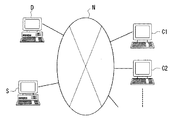
図24は本実施形態のプラズマ処理装置の性能確認システムのシステム構成図である。
この図において、参照符号C1 ,C2 ,……はクライアント・コンピュータ(以下、単にクライアントという)、Sはサーバ・コンピュータ(性能状況情報提供手段,以下単にサーバという)、Dはデータベース・コンピュータ(基準情報記憶手段,以下単にデータベースという)、またNは公衆回線である。クライアントC1 ,C2 ,……とサーバSとデータベースDとは、この図に示すように公衆回線Nを介して相互に接続されている。
【0156】
クライアントC1 ,C2 ,……は、一般に広く普及しているインターネットの通信プロトコル(TCP/IP等)を用いてサーバSと通信する機能(通信機能)を備えたものである。このうち、クライアントC1 (発注者側情報端末)は、発注者が保守者に発注したプラズマ処理装置またはプラズマ処理システムのプラズマチャンバの性能状況を公衆回線Nを介して確認するためのコンピュータであり、サーバSが保持する「プラズマチャンバの性能情報提供ページ」を情報提供ページ(Webページ)として閲覧する機能(プラズマチャンバの性能状況情報閲覧機能)を備えたものである。また、クライアントC2 (保守者側情報端末)は、保守者が上記「性能状況情報」の一部である「第1直列共振周波数f0 情報」をサーバSにアップロードするとともに、クライアントC1 を介して発注者から発せられた電子メールを受信するためのものである。
ここで、プラズマ処理装置又はプラズマ処理システムは、上記の第1〜第3実施形態に準じる構成とされるとともに、チャンバ数等の構成条件は、任意に設定可能なものとされる。
【0157】
上記サーバSの通信機能は、公衆回線Nがアナログ回線の場合にはモデムによって実現され、公衆回線NがISDN(Integrated Services Digital Network)等のデジタル回線の場合には専用ターミナルアダプタ等によって実現される。サーバSは、性能状況情報提供用のコンピュータであり、上記クライアントC1 から受信される閲覧要求に応じて、性能状況情報をインターネットの通信プロトコルを用いてクライアントC1 に送信する。ここで、上述した発注者が保守者からプラズマ処理装置を納入された時点では、性能状況情報を閲覧するための個別の「閲覧専用パスワード」が保守者から個々の発注者に提供されるようになっている。このサーバSは、正規な閲覧専用パスワードが提供された場合のみ、性能状況情報のうち動作保守状況情報をクライアントC1 に送信するように構成されている。
【0158】
ここで、具体的詳細については後述するが、上記「性能状況情報」は、保守者の販売するプラズマ処理装置またはプラズマ処理システムにおけるプラズマチャンバの機種に関する情報、各機種における仕様書としての品質性能情報、納入された各実機における品質性能を示すパラメータの情報、および、このパラメータ、メンテナンスの履歴情報等から構成されている。
このうち、各実機における品質性能、パラメータ、メンテナンスの履歴情報については、「閲覧専用パスワード」が提供された発注者のみに閲覧可能となっている。
【0159】
また、これら「性能状況情報」は、保守者または発注者からサーバSに提供されるとともに実際の動作・保守状況を示す「動作保守状況情報」と、データベースDに蓄積されると共にカタログとして未購入のクライアントが閲覧可能な「性能基準情報」とから構成されるものである。「性能基準情報」は、保守者が各プラズマチャンバによっておこなうプラズマ処理に対して客観的に性能を記述するためのものであり、プラズマCVD、スパッタリングなどの成膜処理においては、成膜状態を予測可能とするものである。
【0160】
本実施形態では、これら「性能基準情報」は、データベースDに蓄積されるようになっている。
サーバSは、クライアントC1 から受信される「性能状況情報」の閲覧要求に対して、データベースDを検索することにより必要な「性能基準情報」を取得して、「性能状況情報提供ページ」として発注者のクライアントC1 に送信するように構成されている。また、サーバSは、「閲覧専用パスワード」が提供された発注者から受信される「性能状況情報」の閲覧要求に対しては、同様に、データベースDを検索することにより必要な「性能基準情報」を取得するとともに、当該「性能基準情報」にクライアントC2 を介して保守者から提供された「動作保守状況情報」を組み合わせて「性能状況情報」を構成し、「性能状況情報提供ページ」として発注者のクライアントC1 に送信するように構成されている。
【0161】
データベースDは、このような「性能状況情報」を構成する「性能基準情報」をプラズマ処理装置またはプラズマ処理システムのプラズマチャンバの機種毎に記憶蓄積するものであり、サーバSから受信される検索要求に応じてこれら「性能基準情報」を読み出してサーバSに転送する。図24では1つのサーバSのみを示しているが、本実施形態では、汎用性のある「性能基準情報」を保守者が複数箇所から管理する複数のサーバ間で共通利用することが可能なように、これらサーバとは個別のデータベースDに「性能基準情報」を蓄積するようにしている。
【0162】
次に、このように構成されたプラズマ処理装置またはプラズマ処理システムの性能確認システムの動作について、図25に示すフローチャートに沿って詳しく説明する。なお、このフローチャートは、上記サーバSにおける「性能状況情報」の提供処理を示すものである。
【0163】
通常、保守者は、不特定の発注者に対して販売するプラズマ処理装置またはプラズマ処理システムにおける各プラズマチャンバの「性能状況情報」、特に「性能基準情報」を購入時の指標として提示することになる。一方、発注者は、この「性能基準情報」によってプラズマチャンバCNにどのような性能、つまりどのようなプラズマ処理が可能なのかを把握することができる。
【0164】
また、保守者は、特定の発注者に対して納入したプラズマ処理装置またはプラズマ処理システムにおけるプラズマチャンバの「性能状況情報」のうち、「性能基準情報」を使用時の指標として提示するとともに、「動作保守状況情報」を動作状態のパラメータとして提示することになる。一方、ユーザーとしての発注者は、「性能基準情報」と「動作保守状況情報」とを比較することによってプラズマ処理装置またはプラズマ処理システムにおける各プラズマチャンバの動作確認をおこなうとともにメンテナンスの必要性を認識し、かつ、プラズマ処理状態の状態を把握することができる。
【0165】
例えば、プラズマ処理装置またはプラズマ処理システムを保守者から購入しようとする発注者は、サーバSにアクセスすることにより、以下のようにして自らが購入しようとするプラズマ処理装置またはプラズマ処理システムの「性能状況情報」の実体を容易に確認することができる。
【0166】
まず、発注者がアクセスしようとした場合には、予め設定されたサーバSのIPアドレスに基づいてクライアントC1 からサーバSに表示要求が送信される。一方、サーバSは、上記表示要求の受信を受信すると(ステップS1)、カタログページCPをクライアントC1 に送信する(ステップS2)。
図26は、このようにしてサーバSからクライアントC1 に送信されたメインページCPの一例である。このカタログページCPには、保守者が販売する多数の機種毎にその「性能状況情報」のうち「性能基準情報」を表示するための機種選択ボタンK1,K2,K3,K4…、と、後述するように、プラズマ処理装置またはプラズマ処理システムを保守者から納入された発注者の使用するカスタマーユーザ画面の表示要求をするためのカスタマーユーザボタンK4から構成されている。
【0167】
例えば、発注者がクライアントC1 に備えられたポインティングデバイス(例えばマウス)等を用いることによって上記プラズマ処理装置またはプラズマ処理システムの機種を選択指定した後、機種選択ボタンK1〜K4…のいずれかを選択指定すると、この指示は、「性能状況情報」のうち「性能基準情報」の表示要求としてサーバSに送信される。
【0168】
この表示要求を受信すると(ステップS3)、サーバSは、選択された機種のうち、表示要求された情報に該当するサブページをクライアントC1 に送信する。すなわち、サーバSは、「性能基準情報」の表示が要求された場合(A)、図27に示すような選択された機種を指定することによってデータベースDから「真空性能」「給排気性能」「温度性能」「プラズマ処理室電気性能」等のデータ、およびこれらのデータにおけるプラズマ処理装置またはプラズマ処理システム毎の、各パラメータのばらつきの値のデータを取得し、これらの掲載された仕様書ページCP1をクライアントC1 に送信する(ステップS4)。
【0169】
仕様書ページCP1には、図27に示すように、選択された機種を示す機種種別K6、真空性能表示欄K7、給排気性能表示欄K8、温度性能表示欄K9、プラズマ処理室電気性能表示欄K10から構成されている。これらは、選択された機種のプラズマチャンバにおける「性能基準情報」に対応するものであり、それぞれ、
真空性能表示欄K7には、
到達真空度 1×10⁻⁴Pa以下
操作圧力 30〜300Pa
給排気性能表示欄K8には、
温度性能表示欄K9には、
ヒータ設定温度 200〜350±10℃
チャンバ設定温度 60〜80±2.0℃
の項目が記載されている。
ここで、SCCM(standard cubic centimeters per minute) は、標準状態(0℃、1013hPa)に換算した際におけるガス流量を表しており、cm3/min に等しい単位を表している。
【0170】
そしてこれらのパラメータPに対して、それぞれのプラズマ処理装置またはプラズマ処理システムにおける各プラズマチャンバ毎のばらつきを、それぞれのパラメータPのうちその最大値Pmax と最小値Pmin のばらつきを、以下の式(10B)
(Pmax −Pmin )/(Pmax +Pmin ) (10B)
として定義し、これらのばらつきの値の各プラズマ処理装置またはプラズマ処理システムにおける設定範囲をそれぞれのパラメータの項目に対して表示する。
【0171】
また、プラズマ処理室電気性能表示欄K10には、前述した第1〜第4実施形態で説明した第1直列共振周波数f0 の値、および、この設定範囲と電力周波数fe との関係が記載される。また、これ以外にも、電力周波数fe におけるプラズマチャンバのレジスタンスRおよびリアクタンスX、そして、プラズマ励起電極4とサセプタ電極8間のプラズマ容量C0 プラズマ励起電極4と、プラズマチャンバの接地電位とされる各部との間のロス容量CX 等の値が記載される。また、仕様書ページCP1には、「プラズマ処理装置またはプラズマ処理システムの納入時においては各パラメータ値がこのページに記載された設定範囲内にあることを保証します」という性能保証の文言が記載される。
【0172】
これにより、従来は、考慮されていなかったプラズマ処理装置またはプラズマ処理システムの全体的な電気的高周波的な特性およびプラズマチャンバの電気的特性のばらつきを購入時の新たなる指標として提示することができる。また、クライアントC1 またはクライアントC2 において、これら性能状況情報をプリンタ等に出力しハードコピーを作ることにより、上記の性能状況情報内容の記載されたカタログまたは仕様書として出力することが可能である。さらに、第1直列共振周波数f0 、レジスタンスR、リアクタンスX、容量C0 ,CX 等の値および上記性能保証の文言をクライアントC1 …の端末、カタログまたは仕様書等に提示することにより、発注者が、電機部品を吟味するようにプラズマチャンバCNの性能を判断して保守者から購入することが可能となる。
【0173】
なお、サーバSは、このようなサブページのクライアントC1 への送信が完了した後に、クライアントC1 から接続解除要求が受信されない場合は(ステップS5)、次のサブページの表示要求を待って待機し(ステップS3)、一方、クライアントC1 から接続解除要求が受信された場合には(ステップS5)、当該クライアントC1 との交信を終了する。
【0174】
また、プラズマ処理装置またはプラズマ処理システムを保守者から納入した発注者は、サーバSにアクセスすることにより、以下のようにして自らが購入したプラズマ処理装置またはプラズマ処理システムにおけるプラズマチャンバの「性能状況情報」の実体を容易に確認することができる。
この発注者は保守者と売買契約を締結した時点で、発注者個別に対応するとともに、購入したプラズマ処理装置またはプラズマ処理システムの機種番号、およびそれぞれのプラズマチャンバの機種番号にも対応可能なカスタマーユーザIDと、プラズマ処理装置またはプラズマ処理システムおよびその各プラズマチャンバの「動作保守状況情報」を閲覧するための個別の「ユーザー専用パスワード(閲覧専用パスワード)」が保守者から個々の発注者に提供されるようになっている。このサーバSは、正規な閲覧専用パスワードが提供された場合のみ、「動作保守状況情報」をクライアントC1 に送信するように構成されている。
【0175】
まず、発注者がアクセスしようとした場合には、前述のカタログページCPにおいて、カスタマーユーザボタンK5を指定操作することにより、発注者はカスタマーユーザ画面の表示要求をサーバSに送信する。
一方、サーバSは、上記表示要求の受信を受信すると(ステップS3−B)、当該発注者に対して、「閲覧専用パスワード」の入力を促す入力要求としてのサブページをクライアントC1 に送信する(ステップS6)。図28はカスタマーユーザページCP2を示すものであり、このカスタマーユーザページCP2はカスタマーユーザID入力欄K11、およびパスワード入力欄K12から構成される。
【0176】
この入力要求としてのカスタマーユーザページCP2はクライアントC1 に表示されるので、発注者は、当該入力要求に応答してプラズマ処理装置またはプラズマ処理システムおよびその各プラズマチャンバの識別を可能とするために、保守者から供与された「閲覧専用パスワード」を「カスタマーユーザID」とともにクライアントC1 に入力することになる。
ここで、発注者は、図28に示すカスタマーユーザID入力欄K11およびパスワード入力欄K12に、それぞれ、カスタマーコードIDとパスワードを入力する。サーバSは、クライアントC1から正規の「カスタマーユーザID」および「閲覧専用パスワード」が受信された場合のみ(ステップS7)、当該「閲覧専用パスワード」に予め関連付けられた「動作保守状況情報」のサブページをクライアントC1 に送信する(ステップS9)。
【0177】
すなわち、「動作保守状況情報」の閲覧は、上記プラズマ処理装置またはプラズマ処理システムの購入契約を締結した特定の発注者のみ、つまり正規の「閲覧専用パスワード」を知り得るもののみに許可されるようになっており、当該発注者以外の第3者がサーバSにアクセスしても「動作保守状況情報」を閲覧することができない。通常、保守者は同時に多数の発注者との間で納入契約を締結するとともに、各々の発注者へ複数のプラズマ処理装置またはプラズマ処理システムの納入を同時に並行して行う場合があるが、上記「閲覧専用パスワード」は、個々の発注者毎および各プラズマ処理装置またはプラズマ処理システムおよびその各プラズマチャンバ毎に相違するものが提供されるので、個々の発注者は、各プラズマ処理装置またはプラズマ処理システムおよびその各プラズマチャンバに対して、それぞれ自らに提供された「閲覧専用パスワード」に関連付けられた「動作保守状況情報」を個別に閲覧することができる。
【0178】
したがって、納入に係わる秘密情報が発注者相互間で漏洩することを確実に防止することができるとともに、複数のプラズマ処理装置またはプラズマ処理システムが納入された場合にでもそれぞれのプラズマ処理装置またはプラズマ処理システムおよびその各プラズマチャンバを個別に識別可能とすることができる。なお、サーバSは、正規の「閲覧専用パスワード」が受信されない場合には(ステップS7)、接続不許可メッセージをクライアントC1 に送信して(ステップS8)、発注者に「閲覧専用パスワード」を再度入力するように促す。発注者が「閲覧専用パスワード」を誤入力した場合には、この機会に正規の入力を行うことにより「動作保守状況情報」を閲覧することができる。
【0179】
このID、パスワードが確認されると(ステップS7)、サーバSは、表示要求された情報に該当するサブページをデータベースDから読み出してクライアントC1 に送信する。すなわち、サーバSは、ユーザIDによって識別された個別のプラズマ処理装置またはプラズマ処理システムおよびその各プラズマチャンバに対する「性能基準情報」「動作保守状況情報」の表示が要求された場合、機種を指定することによってデータベースDから「真空性能」「給排気性能」「温度性能」「プラズマ処理室電気性能」等のデータを取得し、これらの掲載された仕様書ページCP3をクライアントC1 に送信する(ステップS9)。
【0180】
図29は、このようにしてサーバSからクライアントC1 に送信された「動作保守状況情報」のサブページCP3である。このメンテナンス履歴ページCP3には、図29に示すように、納入されたプラズマ処理装置またはプラズマ処理システムおよびその各プラズマチャンバの機械番号を示すロット番号表示K13、真空性能表示欄K7、給排気性能表示欄K8、温度性能表示欄K9、プラズマ処理室電気性能表示欄K10、そして、真空性能メンテナンス欄K14、給排気性能メンテナンス欄K15、温度性能メンテナンス欄K16、プラズマ処理室電気性能メンテナンス欄K17から構成されている。これらは、納入された実機の「性能基準情報」および「動作保守状況情報」に対応するものであり、それぞれ、真空性能表示欄K7、真空性能メンテナンス欄K14には、
到達真空度 1.3×10⁻⁵Pa以下
操作圧力 200Pa
給排気性能表示欄K8、給排気性能メンテナンス欄K15には、
ヒータ設定温度 302.3±4.9℃
チャンバ設定温度 80.1±2.1℃
の項目が記載されている。
【0181】
そしてこれらのパラメータPに対して、それぞれのプラズマ処理装置またはプラズマ処理システムにおける各プラズマチャンバ毎のばらつきを、それぞれのパラメータPのうちその最大値Pmax と最小値Pmin のばらつきを、以下の式(10B)
(Pmax −Pmin )/(Pmax +Pmin ) (10B)
として定義し、これらのばらつきの値の各プラズマ処理装置またはプラズマ処理システムにおける設定範囲をそれぞれのパラメータの項目に対して表示する。
【0182】
さらに、このサブページCP3には、各プラズマチャンバ毎のメンテナンス欄を表示するための「詳細」ボタンK18が各メンテナンス履歴欄K14,K15,K16,K17ごとに設けられ、発注者が、当該情報を閲覧可能となっている。
【0183】
発注者が、当該詳細欄により表示要求をおこなった場合には、メンテナンス履歴の詳細情報の記載されたメンテナンス詳細ページCP4がデータベースDからクライアントC1 に送信する。
【0184】
図30は、このようにしてサーバSからクライアントC1 に送信された「詳細メンテナンス情報」のサブページCP4である。
図には電気性能メンテナンスのページを示している。
このメンテナンス履歴ページCP3には、図30に示すように、納入されたプラズマ処理装置またはプラズマ処理システムおよびその各プラズマチャンバの機械番号を示すロット番号表示K13、選択された各メンテナンス欄が表示される。ここで、各メンテナンス欄としては、各プラズマチャンバに対応するパラメータPのメンテナンス時の値と、これらのパラメータPのばらつきの値とが、プラズマ処理装置またはプラズマ処理システム、および、各プラズマチャンバ毎のロット番号毎に表示される。
【0185】
また、プラズマ処理室電気性能表示欄K10およびプラズマ処理室電気性能メンテナンス欄K17には、前述した第1〜第4実施形態で説明したように、第1直列共振周波数f0 の値、および、この設定範囲と電力周波数fe との関係が記載される。また、これ以外にも、電力周波数fe におけるプラズマチャンバのレジスタンスRおよびアクタンスX、そして、プラズマ励起電極4とサセプタ電極8間のプラズマ容量C0 プラズマ励起電極4と、プラズマチャンバの接地電位とされる各部との間のロス容量CX 等の値が記載される。
【0186】
同時に、データベースDから「性能基準情報」としての「真空性能」「給排気性能」「温度性能」「プラズマ処理室電気性能」等のデータを取得し、これらを図29,図30に示すように、「動作保守状況情報」とセットでメンテナンス履歴ページCP3、メンテナンス詳細ページCP4に表示することにより、「性能基準情報」を参照して「動作保守状況情報」を閲覧することができ、これにより、発注者は、納入されたプラズマ処理装置またはプラズマ処理システムおよびプラズマチャンバの「性能状況情報」のうち、「性能基準情報」を使用時の指標として確認するとともに、「動作保守状況情報」を動作状態を示すパラメータとして検討することができる。同時に、「性能基準情報」と「動作保守状況情報」とを比較することによってプラズマ処理装置またはプラズマ処理システムおよびプラズマチャンバの動作確認をおこなうとともにメンテナンスの必要性を認識し、かつ、プラズマ処理状態の状態を把握することができる。
【0187】
なお、サーバSは、このようなサブページCP3、CP4のクライアントC1 への送信が完了した後に、クライアントC1 から接続解除要求が受信されない場合は(ステップS5)、接続不許可メッセージをクライアントC1 に送信して(ステップS8)、発注者に「閲覧専用パスワード」を再度入力するか、次のサブページの表示要求を待って待機し(ステップS3)、一方、クライアントC1 から接続解除要求が受信された場合には(ステップS5)、当該クライアントC1 との交信を終了する。
【0188】
本実施形態のプラズマ処理装置またはプラズマ処理システムの性能確認システムにおいて、購入発注者が販売保守者に発注したプラズマ処理装置またはプラズマ処理システムの動作性能状況を示す性能状況情報の閲覧を公衆回線を介して要求する購入発注者側情報端末と、販売保守者が前記性能状況情報をアップロードする販売保守者側情報端末と、前記購入発注者側情報端末の要求に応答して、販売保守者側情報端末からアップロードされた性能状況情報を購入発注者側情報端末に提供する性能状況情報提供手段と、を具備することができ、さらに、前記性能状況情報が、前記第1直列共振周波数f0 およびこのパラメータに対して、それぞれのプラズマ処理装置またはプラズマ処理システムにおける各プラズマチャンバ毎のばらつきの値を含むとともに、前記性能状況情報が、カタログまたは仕様書として出力されることにより、販売保守者がアップロードしたプラズマ処理装置またはプラズマ処理システムおよびそのプラズマチャンバの性能基準情報および動作保守状況情報からなる性能状況情報に対して、購入発注者が情報端末から公衆回線を介して閲覧を可能とすることにより、発注者に対して、購入時に判断基準となる情報を伝達することが可能となり、かつ、使用時における、プラズマ処理装置またはプラズマ処理システムおよびそのプラズマチャンバごとの動作性能・保守情報を容易に提供することが可能となる。
また、前記性能状況情報が、上述したようにプラズマチャンバに対する性能パラメータとしての前記第1直列共振周波数f0 およびそのばらつきの値を含むことにより、発注者のプラズマ処理装置またはプラズマ処理システムその各プラズマチャンバに対する性能判断材料を提供できるとともに、購入時における適切な判断をすることが可能となる。さらに、前記性能状況情報を、カタログまたは仕様書として出力することができる。
【0189】
【発明の効果】
本発明のプラズマ処理装置の性能評価方法によれば、プラズマ処理装置を分解、搬送後再組み立てが施されたり、その後被処理物が導入されてプラズマ処理が行われたり、分解掃除、部品交換、組み立て調整等の調整作業が施されたりした際に、プラズマ処理装置の性能が適正に維持されているかどうかを迅速かつ簡便に確認できる。
また、本発明のプラズマ処理装置の保守方法によれば、プラズマ処理装置の性能が適正に維持されていない場合に、迅速に是正が可能となる。
また、本発明のプラズマ処理装置の性能管理システムによれば、納入先において、プラズマ処理装置の性能が適正に維持されるために、納入先におけるプラズマ処理装置の性能評価をメーカー等の搬送元で支援できると共に、メーカー等の搬送元で充実した保守サービス体制を整えることが可能となる。
さらに、本発明のプラズマ処理装置によれば、適正な動作状態に簡便に維持することが可能であり、良好なプラズマ処理を継続して行うことができる。
【図面の簡単な説明】
【図1】本発明に係るプラズマ処理装置の第1実施形態を示す概略構成図である。
【図2】図1におけるプラズマ処理装置の整合回路を示す模式図である。
【図3】本発明に係るプラズマ処理装置の第1実施形態におけるプラズマ処理装置のインピーダンス特性を説明するための模式図である。
【図4】図3におけるプラズマ処理装置の等価回路を示す回路図である。
【図5】第1直列共振周波数f0 を説明するためのインピーダンスZと位相θとの周波数依存特性を示すグラフである。
【図6】本発明に係るプラズマ処理装置の第1実施形態における第1直列共振周波数f0 およびインピーダンスZと位相θとの周波数依存特性を示すグラフである。
【図7】本発明に係るプラズマ処理装置の第2実施形態を示す概略構成図である。
【図8】本発明に係るプラズマ処理装置の第2実施形態におけるプラズマ処理装置のインピーダンス特性を説明するための模式図である。
【図9】図8におけるプラズマ処理装置の等価回路を示す回路図である。
【図10】本発明に係るプラズマ処理装置の第2実施形態における第1直列共振周波数f0 およびインピーダンスZと位相θとの周波数依存特性を示すグラフである。
【図11】本発明に係るプラズマ処理装置の第3実施形態を示す概略構成図である。
【図12】図11におけるプラズマ処理装置の等価回路を示す回路図である。
【図13】本発明に係るプラズマ処理装置の第3実施形態における第1直列共振周波数f0 およびインピーダンスZと位相θとの周波数依存特性を示すグラフである。
【図14】プラズマ発光状態における電極間の状態を示す模式図である。
【図15】インピーダンス測定器のプローブを示す斜視図である。
【図16】図15のインピーダンス測定器のプローブの接続状態を示す模式図である。
【図17】本発明に係るプラズマ処理装置の性能管理システムの第4実施形態におけるシステム構成図である。
【図18】同性能管理システムで実現される評価情報提供方法を示すフローチャートである。
【図19】本発明に係るプラズマ処理装置の性能管理システムの第5実施形態におけるシステム構成図である。
【図20】同性能管理システムで実現される評価情報提供方法を示すフローチャートである。
【図21】本発明に係るプラズマ処理装置の性能管理システムの第5実施形態で実現される評価情報提供方法を示すフローチャートである。
【図22】従来のプラズマ処理装置の一例を示す模式図である。
【図23】従来のプラズマ処理装置の他の例を示す模式図である。
【図24】本発明のプラズマ処理装置の性能確認システムを示すシステム構成図である。
【図25】本発明のプラズマ処理装置の性能確認システムに係わるサーバSの建築状況情報の提供処理を示すフローチャートである。
【図26】本発明のプラズマ処理装置の性能確認システムに係わるメインページCPの構成を示す平面図である。
【図27】本発明のプラズマ処理装置の性能確認システムに係わるサブページCP1の構成を示す平面図である。
【図28】本発明のプラズマ処理装置の性能確認システムに係わるメインページCP2の構成を示す平面図である。
【図29】本発明のプラズマ処理装置の性能確認システムに係わるサブページCP3の構成を示す平面図である。
【図30】本発明のプラズマ処理装置の性能確認システムに係わるサブページCP4の構成を示す平面図である。
【符号の説明】
1…高周波電源
1A…給電線
2…マッチングボックス
2A…整合回路
3…給電板
4…プラズマ励起電極(電極:カソード電極)
5…シャワープレート
6…空間
7…孔
8…ウエハサセプタ(対向電極:サセプタ電極)
9…絶縁体
10…チャンバ壁
10A…チャンバ底部
11…ベローズ
12…サセプタシールド
12A…シールド支持板
12B…支持筒
13…シャフト
16…基板
17…ガス導入管
17a,17b…絶縁体
21…シャーシ
22…ロードコンデンサ
23…コイル
24…チューニングコンデンサ
25…整合回路
26…マッチングボックス
27…第2の高周波電源
27A…給電線
28…給電板(高周波電力配電体)
29…シャーシ
30…コイル
31…チューニングコンデンサ
32…ロードコンデンサ
60…チャンバ室
61…インピーダンス測定用端子(共振周波数測定用端子)
105…プローブ
AN…インピーダンス測定器(共振周波数測定器)
B…分岐点
CN…プラズマチャンバ(プラズマ処理室)
P…プラズマ発光領域
PR,PR’…出力端子位置
SW1,SW2…スイッチ[0001]
TECHNICAL FIELD OF THE INVENTION
The present invention relates to a performance evaluation method, a maintenance method, and a performance management system of a plasma processing apparatus, and a plasma processing apparatus, and in particular, to continuously assure that a plasma processing apparatus keeps desired performance. It relates to techniques suitable for use.
[0002]
[Prior art]
2. Description of the Related Art As an example of a plasma processing apparatus that performs plasma processing such as CVD (chemical vapor deposition), sputtering, dry etching, and ashing, a so-called two-frequency excitation type as shown in FIG. 22 is conventionally known.
In the plasma processing apparatus shown in FIG. 22, a
[0003]
High frequency power from the high
Under the plasma excitation electrode (cathode electrode) 4, a
[0004]
The gas introduced from the
On the other hand, a wafer susceptor (susceptor electrode) 8 on which the
[0005]
The
A second high
[0006]
FIG. 23 shows another example of a conventional plasma processing apparatus. Unlike the plasma processing apparatus shown in FIG. 22, the plasma processing apparatus shown in FIG. 23 is a single-frequency excitation type plasma processing apparatus. That is, high-frequency power is supplied only to the
[0007]
In the above-described plasma processing apparatus, generally, power at a frequency of about 13.56 MHz is supplied to generate plasma between the
[0008]
As a method of confirming the operation of such a plasma processing apparatus and evaluating the operation, for example, a method of actually performing processing such as film formation and evaluating the film formation characteristics is performed as follows. I was
(1) Deposition rate and in-plane uniformity
(1) A desired film is formed on a substrate by plasma CVD.
{Circle around (2)} Patterning of the resist is performed.
(3) The film is dry-etched.
(4) The resist is removed by ashing.
{Circle around (5)} The film thickness step is measured by a stylus step meter.
{Circle around (6)} The deposition rate is calculated from the film formation time and the film thickness.
{Circle around (7)} In-film uniformity is measured at 16 points on the 6-inch substrate surface.
(2) BHF etching rate
The resist mask is patterned in the same manner as (1) (1) and (2).
(3) The substrate is immersed in the BHF solution for 1 minute.
(4) After washing with pure water and drying, the resist is H2SO4+ H2O2 To peel off.
(5) The step is measured in the same manner as in (1) (5) above.
(6) The etching rate is calculated from the immersion time and the step.
(3) Isolation voltage
(1) A conductive film is formed on a glass substrate by sputtering, and is patterned as a lower electrode.
(2) An insulating film is formed by plasma CVD.
(3) An upper electrode is formed in the same manner as in (1).
(4) A contact hole is formed for the lower electrode.
(5) Probe the upper and lower electrodes and measure the IV characteristics (current-voltage characteristics). At this time, the maximum voltage is applied up to about 200V.
{Circle around (6)} The electrode area is 100 μm square, and 1 μA / cm crosses 100 pA.2 Therefore, V at this time is defined as the withstand voltage.
[0009]
Further, with respect to the plasma processing apparatus as described above, conventionally, when used in the production of semiconductors and liquid crystals, the plasma processing speed (deposition speed during film formation and processing speed) is high and the productivity is high; In recent years, the large size of the substrate to be processed has been excellent in that the plasma processing in the in-plane direction of the substrate to be processed has excellent uniformity (in-plane distribution of film thickness and in-plane distribution of processing variation). Along with this, it is getting stronger.
In addition, as the size of the substrate to be processed increases, the amount of power input also increases until a kW order is input, and the power consumption tends to increase. For this reason, it is desired that the development cost of the power supply increases with the increase in the capacity of the power supply, and that the running cost is reduced because the power consumption increases during the operation of the apparatus.
In addition, an increase in power consumption increases an emission of carbon dioxide, which is an environmental load. This is because, as the size of the substrate to be processed increases, the emission amount further increases, and the power consumption efficiency further decreases, so that the power consumption increases. Therefore, the demand for reducing the emission amount of carbon dioxide also increases. I have.
On the other hand, as compared with 13.56 MHz which has been generally used as the plasma excitation frequency, by increasing the frequency in the VHF band of 30 MHz or more, which is higher than the conventional frequency, effective energy consumed in the plasma space is achieved. Power can be increased. As a result, the plasmaCVDIn such a volume apparatus, there has been a possibility that the deposition rate during film formation can be improved.
[0010]
Further, with respect to a plasma processing apparatus having a plurality of plasma chambers as described above, for each plasma chamber, a difference in plasma processing is eliminated, and a plasma processing is performed even on a substrate to be processed in a different plasma chamber. Processing speed (deposition speed during film formation and processing speed), productivity, and uniformity of plasma processing in the in-plane direction of the substrate to be processedWant to improve(I want to eliminate processing variations such as in-plane distribution of film thickness))There is a request that.
At the same time, for a plasma processing apparatus having a plurality of plasma chambers, the same process recipe in which external parameters such as gas flow rate and pressure to be supplied, power supply, and processing time are equal to each plasma chamber is applied, It is desired that substantially the same plasma processing results can be obtained.
In addition, when installing a new plasma processing apparatus or performing adjustment / maintenance / inspection, adjustments required to eliminate machine differences among multiple plasma chambers, eliminate processing variations, and obtain substantially the same processing results with the same process recipe Along with a need for a reduction in time, a reduction in the cost required for such adjustment has been required.
[0011]
Further, with respect to a plasma processing system having a plurality of plasma processing apparatuses as described above, similarly, there is a demand for eliminating individual differences in plasma processing for individual plasma chambers in each plasma processing apparatus. Was.
[0012]
[Problems to be solved by the invention]
As described above, the plasma processing apparatus has a desired level of performance, and in a plasma processing apparatus or a plasma processing system including a plurality of plasma chambers (plasma processing chambers), there is a difference in the performance of the plasma processing. Consideration was needed to eliminate the problem. However, even in a plasma processing apparatus in which such considerations are sufficiently taken into consideration, there is a possibility that a desired performance level cannot be maintained or a machine difference between a plurality of plasma processing chambers occurs during repeated plasma processing. there were. In addition, when adjustment work such as disassembly cleaning, component replacement, and assembly adjustment is performed, the performance before the adjustment work may not be maintained due to inadequate adjustment or the like. Further, when transporting the plasma processing apparatus, generally,OnceDisassembly, transport, and reassembly at the destination are performed. Also in this case, there is a risk that the performance before the conveyance is not maintained due to vibrations during the conveyance or inadequate reassembly work.
[0013]
As an evaluation method for confirming whether or not the performance of such a plasma processing apparatus is maintained within a desired performance level or within a desired machine error, the operation evaluation as described in the above (1) to (3) is performed. When the method is adopted, it is necessary to operate the plasma processing apparatus, and it is necessary to process and measure the substrate to be processed in a plurality of steps at an inspection place different from the installation place of the plasma processing apparatus. .
For this reason, it takes several days or weeks for the evaluation result to be obtained, and if the production line is not stopped during that period, the characteristics of the substrate subjected to the plasma processing are unknown. When the condition was not good,Products processed by the plasma processing equipmentSince there is a possibility that the standard of the product may not be reached, there has been a demand to maintain the operation of the plasma processing apparatus in an appropriate state by a simpler method.
[0014]
The present invention has been made in view of the above circumstances, and aims to achieve the following objects.
(1) To provide a quick and simple evaluation method for confirming whether or not the performance of a plasma processing apparatus is properly maintained.
(2) To provide a maintenance method that can quickly correct the performance of the plasma processing apparatus when it is not properly maintained.
(3) To provide a performance management system for managing the plasma processing apparatus so that the performance of the plasma processing apparatus is appropriately maintained at the delivery destination.
(4) To provide a plasma processing apparatus that can easily maintain an appropriate operation state.
[0015]
[Means for Solving the Problems]
In order to solve the above problems, a performance evaluation method for a plasma processing apparatus according to the present invention includes:
A plasma processing chamber having electrodes for exciting plasma,
A high-frequency power supply for supplying high-frequency power to the electrode;
An impedance matching between the plasma processing chamber and the high-frequency power supply having an input terminal and an output terminal by connecting the high-frequency power supply to the input terminal and connecting a high-frequency power distribution body connected to the electrode to the output terminal. And a matching circuit to obtain
A method for evaluating the performance of a plasma processing apparatus comprising:
An end of the high-frequency power distributor connected to the output terminal of the matching circuit when supplying the high-frequency powerIsAt the measurement positionDuring non-plasma emissionMeasured high frequency characteristics A of the plasma processing chamber(However, the high frequency characteristic A is any one of the resonance frequency f, the impedance Z at the frequency of the high frequency power, the resistance R at the frequency of the high frequency power, or the reactance X at the frequency of the high frequency power.)At time t0And subsequent time t1A at0, A1The absolute value of the difference ΔA of
Its
[0016]
In order to solve the above problems, a performance evaluation method for a plasma processing apparatus according to the present invention includes: A plasma processing chamber having electrodes for exciting plasma,
A high-frequency power supply for supplying high-frequency power to the electrode,
The plasma processing chamber is connected to the input terminal by connecting the high-frequency power supply to the input terminal via the high-frequency power supply while connecting the high-frequency power distributor connected to the electrode having an input terminal and an output terminal. A matching circuit for obtaining impedance matching with the high-frequency power supply;
A method for evaluating the performance of a plasma processing apparatus comprising:
The high-frequency power supply-side end of the high-frequency power feeder connected to the high-frequency power supply when supplying the high-frequency powerIsAt the measurement positionDuring non-plasma emissionMeasured high frequency characteristics A of the plasma processing chamber(However, the high frequency characteristic A is any one of the resonance frequency f, the impedance Z at the frequency of the high frequency power, the resistance R at the frequency of the high frequency power, or the reactance X at the frequency of the high frequency power.)At time t0And subsequent time t1A at0, A1The absolute value of the difference ΔA of
Its
[0017]
In order to solve the above problems, a performance evaluation method for a plasma processing apparatus according to the present invention includes: A plasma processing chamber having an electrode for exciting plasma, a high-frequency power supply for supplying high-frequency power to the electrode,
The plasma processing chamber is connected to the input terminal by connecting the high-frequency power supply to the input terminal via the high-frequency power supply while connecting the high-frequency power distributor connected to the electrode having an input terminal and an output terminal. A matching circuit for obtaining impedance matching with the high-frequency power supply;
A method for evaluating the performance of a plasma processing apparatus comprising:
The input terminal connected to the high-frequency power feeder when supplying the high-frequency powerIsAt the measurement positionDuring non-plasma emissionMeasured high frequency characteristics A of the plasma processing chamber(However, the high frequency characteristic A is any one of the resonance frequency f, the impedance Z at the frequency of the high frequency power, the resistance R at the frequency of the high frequency power, or the reactance X at the frequency of the high frequency power.)At time t0And subsequent time t1A at0, A1The absolute value of the difference ΔA of
Its
[0018]
In the above, the high frequency characteristic A is the first series resonance frequency f 0 It may be.
In the above, the time t 0 And subsequent time t 1 During this time, an object to be processed may be introduced into the plasma processing chamber, and the object to be processed may be subjected to plasma processing.
In the above, the time t 0 And subsequent time t 1 In the meantime, the plasma processing apparatus may be subjected to adjustment work such as disassembly cleaning, component replacement, and assembly adjustment.
In the above, the time t 0 And subsequent time t 1 In this case, disassembly, transportation, and reassembly may be performed.
In the present invention, as a result of the evaluation method described above, the absolute value of ΔA 0 The maintenance method of the plasma processing apparatus, characterized in that the correction operation of the high frequency characteristic A is performed when the ratio is 10% or more. The high frequency characteristic A is the first series resonance frequency f 0 It may be.
[0019]
Further, a performance management system for a plasma processing apparatus according to the present invention includes a plasma processing chamber having electrodes for exciting plasma,
A high-frequency power supply for supplying high-frequency power to the electrode;
An impedance matching between the plasma processing chamber and the high-frequency power supply having an input terminal and an output terminal by connecting the high-frequency power supply to the input terminal and connecting a high-frequency power distribution body connected to the electrode to the output terminal. And a matching circuit to obtain
A performance management system for a plasma processing apparatus comprising:
An end of the high-frequency power distributor connected to the output terminal of the matching circuit when supplying the high-frequency powerIsAt the measurement positionDuring non-plasma emissionMeasured high frequency characteristics A of the plasma processing chamber(However, the high frequency characteristic A is any one of the resonance frequency f, the impedance Z at the frequency of the high frequency power, the resistance R at the frequency of the high frequency power, or the reactance X at the frequency of the high frequency power.)At time t0A at0And a delivery destination input / output device connected to the server via a communication line.
The server has the high frequency characteristic A0Time t after1A at1Is received from the destination input / output device, and the A0And this A1And the absolute value of ΔA, which is the difference between
Its
[0020]
Further, the performance management system of the plasma processing apparatus according to the present invention, a plasma processing chamber having an electrode for exciting plasma, a high-frequency power supply for supplying high-frequency power to the electrode,
The plasma processing chamber is connected to the input terminal by connecting the high-frequency power supply to the input terminal via the high-frequency power supply while connecting the high-frequency power distributor connected to the electrode having an input terminal and an output terminal. A matching circuit for obtaining impedance matching with the high-frequency power supply;
A performance management system for a plasma processing apparatus comprising:
The high-frequency power supply-side end of the high-frequency power feeder connected to the high-frequency power supply when supplying the high-frequency powerIsAt the measurement positionDuring non-plasma emissionMeasured high frequency characteristics A of the plasma processing chamber(However, the high frequency characteristic A is any one of the resonance frequency f, the impedance Z at the frequency of the high frequency power, the resistance R at the frequency of the high frequency power, or the reactance X at the frequency of the high frequency power.)At time t0A at0And a delivery destination input / output device connected to the server via a communication line.
The server has the high frequency characteristic A0Time t after1A at1Is received from the destination input / output device, and the A0And this A1And the absolute value of ΔA, which is the difference between
Its
[0021]
Further, a performance management system for a plasma processing apparatus according to the present invention includes a plasma processing chamber having electrodes for exciting plasma,
A high-frequency power supply for supplying high-frequency power to the electrode,
The plasma processing chamber is connected to the input terminal by connecting the high-frequency power supply to the input terminal via the high-frequency power supply while connecting the high-frequency power distributor connected to the electrode having an input terminal and an output terminal. A matching circuit for obtaining impedance matching with the high-frequency power supply;
A performance management system for a plasma processing apparatus comprising:
The input terminal connected to the high-frequency power feeder when supplying the high-frequency powerIsAt the measurement positionDuring non-plasma emissionMeasured high frequency characteristics A of the plasma processing chamber(However, the high frequency characteristic A is any one of the resonance frequency f, the impedance Z at the frequency of the high frequency power, the resistance R at the frequency of the high frequency power, or the reactance X at the frequency of the high frequency power.)At time t0A at0And a delivery destination input / output device connected to the server via a communication line.
The server has the high frequency characteristic A0Time t after1A at1Is received from the destination input / output device, and the A0And this A1And the absolute value of ΔA, which is the difference between
Its
[0022]
Further, the performance management system of the plasma processing apparatus according to the present invention,The high frequency characteristic A is the first series resonance frequency f 0 It may be.
In the performance management system for a plasma processing apparatus according to the present invention, the time t 0 And subsequent time t 1 In the meantime, an object to be processed is introduced into the plasma processing chamber, and plasma processing is performed on the object to be processed.
In the performance management system for a plasma processing apparatus according to the present invention, the time t 0 And subsequent time t 1 In the meantime, the plasma processing apparatus may be subjected to adjustment work such as disassembly cleaning, component replacement, and assembly adjustment.
In the performance management system for a plasma processing apparatus according to the present invention, the time t 0 And subsequent time t 1 In this case, disassembly, transportation, and reassembly may be performed.
In the performance management system for a plasma processing apparatus according to the present invention, the server may include an A for each unique number of the plasma processing chamber. 0 Is received, and the unique number of the delivered plasma processing chamber is received from the delivery input / output device, and A corresponding to the unique number is received. 0 The operation may be performed by using.
In the performance management system for a plasma processing apparatus according to the present invention, an impedance measuring instrument connected to the plasma processing apparatus is connected to the delivery input / output device, and the impedance measuring instrument is connected to 1 May be directly transmitted.
In the performance management system for a plasma processing apparatus according to the present invention, the server includes an output device at a transfer source, and the absolute value of ΔA is A 0 The maintenance device may output a maintenance work command from the output device when the value exceeds 10% of the value.
[0023]
A performance management system for a plasma processing apparatus according to the present invention includes a plasma processing chamber having electrodes for exciting plasma,
A high-frequency power supply for supplying high-frequency power to the electrode;
An impedance matching between the plasma processing chamber and the high-frequency power supply having an input terminal and an output terminal by connecting the high-frequency power supply to the input terminal and connecting a high-frequency power distribution body connected to the electrode to the output terminal. And a matching circuit to obtain
A performance management system for a plasma processing apparatus comprising:
An end of the high-frequency power distributor connected to the output terminal of the matching circuit when supplying the high-frequency powerIsAt the measurement positionDuring non-plasma emissionMeasured high frequency characteristics A of the plasma processing chamber(However, the high frequency characteristic A is any of the resonance frequency f, the impedance Z at the frequency of the high frequency power, the resistance R at the frequency of the high frequency power, or the reactance X at the frequency of the high frequency power.)Time t0A at0When,Time t after the high frequency characteristic A 1 A at 1 And a plurality of failure levels are set in accordance with the absolute value of ΔA, which is the difference betweenA server that stores information of the service engineer registered corresponding to the failure level, an output device at the transport source of the server, and a delivery input / output device connected to the server by a communication line,
The server has the high frequency characteristic A0Time t after1A at1Is received from the destination input / output device, and the A0And this A1And the absolute value of ΔA, which is the difference between
Its value isSet earlierIf the failure level is any of the failure levels, the output device outputs a maintenance work instruction together with the failure level and information of a service engineer registered corresponding to the failure level.
[0024]
A performance management system for a plasma processing apparatus according to the present invention includes a plasma processing chamber having electrodes for exciting plasma,
A high-frequency power supply for supplying high-frequency power to the electrode,
The plasma processing chamber is connected to the input terminal by connecting the high-frequency power supply to the input terminal via the high-frequency power supply while connecting the high-frequency power distributor connected to the electrode having an input terminal and an output terminal. A matching circuit for obtaining impedance matching with the high-frequency power supply;
A performance management system for a plasma processing apparatus comprising:
The high-frequency power supply-side end of the high-frequency power feeder connected to the high-frequency power supply when supplying the high-frequency powerIsAt the measurement positionDuring non-plasma emissionMeasured high frequency characteristics A of the plasma processing chamber(However, the high frequency characteristic A is any of the resonance frequency f, the impedance Z at the frequency of the high frequency power, the resistance R at the frequency of the high frequency power, or the reactance X at the frequency of the high frequency power.)Time t0A at0When,Time t after the high frequency characteristic A 1 A at 1 And a plurality of failure levels are set in accordance with the absolute value of ΔA, which is the difference betweenA server that stores information of the service engineer registered corresponding to the failure level, an output device at the transport source of the server, and a delivery input / output device connected to the server by a communication line,
The server has the high frequency characteristic A0Time t after1A at1Is received from the destination input / output device, and the A0And this A1And the absolute value of ΔA, which is the difference between
Its value isSet earlierIf the failure level is any of the failure levels, the output device outputs a maintenance work instruction together with the failure level and information of a service engineer registered corresponding to the failure level.
[0025]
A performance management system for a plasma processing apparatus according to the present invention includes a plasma processing chamber having electrodes for exciting plasma,
A high-frequency power supply for supplying high-frequency power to the electrode,
The plasma processing chamber is connected to the input terminal by connecting the high-frequency power supply to the input terminal via the high-frequency power supply while connecting the high-frequency power distributor connected to the electrode having an input terminal and an output terminal. A matching circuit for obtaining impedance matching with the high-frequency power supply;
A performance management system for a plasma processing apparatus comprising:
The input terminal connected to the high-frequency power feeder when supplying the high-frequency powerIsAt the measurement positionDuring non-plasma emissionMeasured high frequency characteristics A of the plasma processing chamber(However, the high frequency characteristic A is any of the resonance frequency f, the impedance Z at the frequency of the high frequency power, the resistance R at the frequency of the high frequency power, or the reactance X at the frequency of the high frequency power.)Time t0A at0When,Time t after the high frequency characteristic A 1 A at 1 And a plurality of failure levels are set in accordance with the absolute value of ΔA, which is the difference betweenA server that stores information of the service engineer registered corresponding to the failure level, an output device at the transport source of the server, and a delivery input / output device connected to the server by a communication line,
The server has the high frequency characteristic A0Time t after1A at1Is received from the destination input / output device, and the A0And this A1And the absolute value of ΔA, which is the difference between
Its value isSet earlierIf the failure level is any of the failure levels, the output device outputs a maintenance work instruction together with the failure level and information of a service engineer registered corresponding to the failure level.
[0026]
In the performance management system for a plasma processing apparatus according to the present invention, the high-frequency characteristic A is the first series resonance frequency f0 It may be characterized by the following.
In the performance management system for a plasma processing apparatus according to the present invention, the time t0And subsequent time t1In the meantime, an object to be processed is introduced into the plasma processing chamber, and plasma processing is performed on the object to be processed.
In the performance management system for a plasma processing apparatus according to the present invention, the time t0And subsequent time t1In the meantime, the plasma processing apparatus may be subjected to adjustment work such as disassembly cleaning, component replacement, and assembly adjustment.
In the performance management system for a plasma processing apparatus according to the present invention, the time t0And subsequent time t1In this case, disassembly, transportation, and reassembly may be performed.
[0027]
In the performance management system for a plasma processing apparatus according to the present invention, the server may be configured to perform A0Is received, and the unique number of the delivered plasma processing chamber is received from the delivery input / output device, and A corresponding to the unique number is received.0The calculation is performed using
In the performance management system for a plasma processing apparatus according to the present invention, an impedance measuring instrument connected to the plasma processing apparatus is connected to the destination input / output device, and the impedance measuring instrument is connected to the server from the impedance measuring instrument.1May be directly transmitted.
In the performance management system for a plasma processing apparatus according to the present invention, the server may also transmit the failure level to the destination input / output device.
[0028]
A plasma processing apparatus according to the present invention includes a plasma processing chamber having an electrode for exciting plasma, a high-frequency power supply for supplying high-frequency power to the electrode,
An impedance matching between the plasma processing chamber and the high-frequency power supply having an input terminal and an output terminal by connecting the high-frequency power supply to the input terminal and connecting a high-frequency power distribution body connected to the electrode to the output terminal. And a matching circuit to obtain
A plasma processing apparatus comprising:
An end of the high-frequency power distributor connected to the output terminal of the matching circuit when supplying the high-frequency powerIsAt the measurement positionDuring non-plasma emissionMeasured high frequency characteristics A of the plasma processing chamber(However, the high frequency characteristic A is any of the resonance frequency f, the impedance Z at the frequency of the high frequency power, the resistance R at the frequency of the high frequency power, or the reactance X at the frequency of the high frequency power.)At time t0And subsequent time t1A at0, A1Is the absolute value of the difference ΔASaid A 0 10% ofIt is characterized by being maintained at a smaller value.
[0029]
A performance management system for a plasma processing apparatus according to the present invention includes a plasma processing chamber having electrodes for exciting plasma, a high-frequency power supply for supplying high-frequency power to the electrodes,
The plasma processing chamber is connected to the input terminal by connecting the high-frequency power supply to the input terminal via the high-frequency power supply while connecting the high-frequency power distributor connected to the electrode having an input terminal and an output terminal. A matching circuit for obtaining impedance matching with the high-frequency power supply;
A plasma processing apparatus comprising:
The high-frequency power supply-side end of the high-frequency power feeder connected to the high-frequency power supply when supplying the high-frequency powerIsAt the measurement positionDuring non-plasma emissionMeasured high frequency characteristics A of the plasma processing chamber(However, the high frequency characteristic A is any of the resonance frequency f, the impedance Z at the frequency of the high frequency power, the resistance R at the frequency of the high frequency power, or the reactance X at the frequency of the high frequency power.)At time t0And subsequent time t1A at0, A1Is the absolute value of the difference ΔASaid A 0 10% ofIt is characterized by being maintained at a smaller value.
[0030]
A plasma processing apparatus according to the present invention has a plasma processing chamber having electrodes for exciting plasma,
A high-frequency power supply for supplying high-frequency power to the electrode,
The plasma processing chamber is connected to the input terminal by connecting the high-frequency power supply to the input terminal via the high-frequency power supply while connecting the high-frequency power distributor connected to the electrode having an input terminal and an output terminal. A matching circuit for obtaining impedance matching with the high-frequency power supply;
A plasma processing apparatus comprising:
The input terminal connected to the high-frequency power feeder when supplying the high-frequency powerIsAt the measurement positionDuring non-plasma emissionMeasured high frequency characteristics A of the plasma processing chamber(However, the high frequency characteristic A is any of the resonance frequency f, the impedance Z at the frequency of the high frequency power, the resistance R at the frequency of the high frequency power, or the reactance X at the frequency of the high frequency power.)At time t0And subsequent time t1A at0, A1Is the absolute value of the difference ΔASaid A 0 10% ofIt is characterized by being maintained at a smaller value.
[0031]
In the plasma processing apparatus according to the present invention, the high-frequency characteristic A is the first series resonance frequency f0 It may be characterized by the following.
[0032]
The plasma processing apparatus according to the present invention operates at time t0And subsequent time t1During this time, an object to be processed may be introduced into the plasma processing chamber, and the object to be processed may be subjected to plasma processing.
[0033]
The plasma processing apparatus according to the present invention operates at time t0And subsequent time t1In the meantime, the plasma processing apparatus is subjected to adjustment work such as disassembly cleaning, component replacement, and assembly adjustment.
[0034]
The plasma processing apparatus according to the present invention operates at time t0And subsequent time t1And disassembly, transportation, and reassembly are performed.
[0035]
In the performance management system for a plasma processing apparatus according to the present invention, the absolute value of
[0038]
Hereinafter, each of the above inventions will be described in more detail.
In each of the above inventions, the high-frequency characteristic A measured when supplying high-frequency power to the electrodes of the plasma processing chamber was used as an evaluation index. This is because the high-frequency characteristic A has a close relationship with the performance of the plasma processing apparatus such as the effective power consumed in the plasma space, and also has a problem in that the performance becomes poor, such as contamination and the assembling accuracy being disturbed. It focuses on the fact that when an adverse event occurs, the value easily fluctuates. Then, the high frequency characteristic A used as the index is calculated at time t.0And subsequent time t1A at0, A1It is found that the absolute value of the difference ΔA is closely related to the performance variation width of the plasma processing apparatus, and that if this value is smaller than a predetermined value, the performance variation width can be considered to be within a predetermined range. By comparing the absolute value of ΔA with a predetermined value, the performance of the plasma processing apparatus can be evaluated.
That is, at the time of new installation after disassembly / transportation, repetition of plasma processing due to subsequent use, or adjustment / maintenance / inspection, etc., whether the performance of the plasma processing chamber maintains a predetermined performance level, In the case where there are a plurality of test results, it is possible to evaluate whether or not the difference in performance is sufficiently suppressed.
[0039]
Since the measurement of the high-frequency characteristic A can be performed instantaneously, the evaluation time can be greatly reduced as compared with the case where a conventional inspection method using actual film formation on a substrate or the like is employed. Further, it is possible to reduce costs such as the cost of an inspection board and the like necessary for performance evaluation, the inspection processing cost of the inspection board, and the labor cost of workers engaged in the evaluation work.
Therefore, according to the method for evaluating a plasma processing apparatus according to the present invention, performance evaluation of the plasma processing apparatus can be performed instantaneously and at no cost. Further, according to the maintenance method of the present invention, the performance evaluation result can be performed instantaneously and at no cost, so that the performance evaluation is performed at a desired frequency, and the result is immediately reflected to corrective work. It can be carried out. Further, according to the performance management system of the plasma processing apparatus according to the present invention, the user or the like at the delivery destination can easily know the performance evaluation result by using the server managed by the manufacturer or the like. In addition, according to the plasma processing apparatus of the present invention, since the performance is maintained by the index that can be constantly checked, that is, the high frequency characteristic A, it is possible to perform good plasma processing. Further, according to the performance check system of the plasma processing apparatus according to the present invention, the purchase orderer can easily know the operation performance status of the plasma processing apparatus by using the server managed by the sales and maintenance person.
[0040]
Therefore, any of the inventions avoids performing a problematic plasma processing operation in advance and contributes to maintaining the plasma processing apparatus in a good state. In addition, the same process recipe is always applied to the plasma processing chamber to obtain substantially the same plasma processing result. That is, for example, when a film is formed in a plasma chamber, the film thickness, dielectric strength, etching, This makes it possible to continuously obtain a film having substantially uniform film characteristics such as a rate.
When the plasma processing apparatus has a plurality of plasma chambers or a plurality of plasma processing apparatuses are combined to form a plasma processing system, the high-frequency characteristic A is obtained for each plasma chamber. It can be an index.
[0041]
In each of the above inventions, the measurement position of the high-frequency characteristic A may be a measurement position that is an end of the high-frequency power distribution body connected to an output terminal of the matching circuit when supplying the high-frequency power.
Thus, by evaluating the change in the high frequency characteristics, it is possible to evaluate the change in the effective power consumed in the plasma space. Then, it is possible to evaluate whether substantially the same plasma processing result can be obtained by applying the same process recipe.
[0042]
Further, in the present invention, the measurement position, which is the input terminal connected to the high-frequency power feeder (feed line) when the high-frequency power is supplied, is changed to the above-described measurement position. It can be a measurement position.
This makes it possible to evaluate not only the plasma processing chamber but also the electrical high-frequency characteristics including the matching circuit. Therefore, the evaluation of the effective power consumed in the plasma space and the evaluation of the plasma processing result can be performed more accurately than the evaluation at the measurement position.
[0043]
Further, in place of the above-described measurement position, the measurement position which is the high-frequency power supply side end of the high-frequency power supply body (feed line) connected to the high-frequency power supply when the high-frequency power is supplied is set to the high-frequency characteristic. A can be the measurement position of A.
This makes it possible to evaluate the electrical high-frequency characteristics not only of the plasma processing chamber and the matching circuit, but also of the high-frequency power feeder. Therefore, the evaluation of the effective power consumed in the plasma space and the evaluation of the plasma processing result can be performed more accurately than the evaluation at the two measurement positions.
[0044]
In the above inventions, the high frequency characteristic A can be any one of a resonance frequency f, an impedance Z at the frequency of the high frequency power, a resistance R at a frequency of the high frequency power, or a reactance X at a frequency of the high frequency power. . This makes it possible to evaluate the plasma processing apparatus with electrical high-frequency characteristics. Note that, as described later, the first resonance frequency f of the plasma processing chamber measured at the end of the high-frequency power distribution unit connected to the output terminal of the matching circuit when supplying high-frequency power is described later.f 0 Or the series resonance frequency defined by the capacitance with the counter electrode that generates plasma in cooperation with the electrodef 0 'Or can be adopted.
As the high-frequency characteristic A, an amplitude ratio of the voltage / current represented by
[0045]
(Equation 1)
(Equation 2)
Here, when the impedance Z is adopted as the high-frequency characteristic A, since the impedance Z is a value at the frequency of plasma excitation, a parameter that can be grasped only by measuring the frequency dependency between Z and θ. It is not necessary to see the frequency dependence of the high frequency characteristics of the plasma chamber for the resonance frequency f, which is easier to grasp than the resonance frequency f. Also, at the frequency of plasma excitation of the plasma chamberElectrical high frequency characteristicsIs a parameter that can be more directly captured.
Further, when the resistance R and the reactance X are adopted, the impedance at the frequency at which the plasma of the plasma chamber is excited is more directly compared with the case where the impedance Z which is the vector amount of the resistance R and the reactance X is observed.Electrical high frequency characteristicsCan be captured.
[0048]
The high frequency characteristic A includes a first series resonance frequency f0 Can be adopted.
This first series resonance frequency f0 Is an electrical high-frequency characteristic determined by a mechanical structure as a major factor, and is considered to be different for each plasma processing chamber (plasma chamber). Also, the first series resonance frequency f0 Is considered to be an evaluation index closely related to stability of plasma generation and uniform operation.
Thereby, the first series resonance frequency f0 When is selected, more accurate performance evaluation can be performed.
[0049]
When the resonance frequency f is adopted as the high frequency characteristic A, the first series resonance frequency f0 Since the focus is also on the series-parallel resonance frequency other than the above, the characteristics of all the current paths branched in the chamber will be observed. Therefore, the first series resonance frequency f0 Compared to the case of using, there is a merit that the machine difference can be confirmed in more detail, but there is a demerit that the analysis requires time and effort.
[0050]
Here, the first series resonance frequency f0 The definition will be described.
First, the frequency dependence of the impedance of the plasma chamber is measured. At this time, an impedance measurement range of the plasma chamber is defined as described later, and the supplied power frequency fe The frequency dependence of the impedance of the plasma chamber is measured by measuring the impedance vector amount (Z, θ) by changing the measurement frequency in a range including the above. Here, for example, the power frequency f set to a value such as 13.56 MHz, 27.12 MHz, 40.68 MHz, or the like.e , The measurement frequency is set in a range of, for example, about 1 MHz to 100 MHz.
FIG. 6 shows the first series resonance frequency f0 6 is a graph showing frequency dependence characteristics of impedance Z and phase θ for explaining the following.
Next, as shown in FIG. 6, the impedance characteristic curve and the phase curve are plotted by plotting the impedance Z and the phase θ with respect to the measurement frequency, and the minimum value of the impedance among the minimum values of the impedance Z, that is, the measurement frequency The frequency at which the phase θ becomes zero when the phase θ changes from minus to plus for the first time counting from the lower side of the first series resonance frequency f0 Is defined as
[0051]
Next, the above-described impedance measurement range (high-frequency characteristic measurement range) of the plasma chamber will be described.
A high frequency power supply is connected to the plasma chamber via a matching circuit, and the output side of the matching circuit on the output side is set as an impedance measurement range.
Here, most of the matching circuits are configured to include a plurality of passive elements in order to adjust impedance in response to changes in the plasma state or the like in the plasma chamber.
FIG. 2 is a schematic diagram showing the
For example, as shown in FIG. 2, as the
[0052]
Further, instead of the measurement position, as shown in FIG. 2, a power supply line (high-frequency power feeder) 1A connecting the high-
Further, as shown in FIG. 2, the power supply line (high-frequency power feeder) 1A connecting the high-
[0053]
In each of the above inventions, the high-frequency characteristic A at time t0And subsequent time t1A at0, A1The predetermined value to be compared with the absolute value of the difference ΔA is not particularly limited.0Can be set to 10%. In this case, for example, in a plasma CVD apparatus, the fluctuation of the deposition rate can be suppressed within 5%.
Further, more preferably, A0Can be set to 3%. In this case, for example, in a plasma CVD apparatus, the fluctuation of the deposition rate can be suppressed within 2%.
[0054]
The performance management system for a plasma processing apparatus according to the present invention is, for example, when delivering a plasma processing apparatus to a user or the like from a plasma processing apparatus maker, a distributor, a maintenance company, or the like, disassembling at a transport source, and transporting the plasma processing apparatus to a destination. Then, after passing through a series of processing steps of reassembling at the delivery destination or during a subsequent use period, the time t0Time t after a certain time has passed since1Is a system for evaluating whether the performance of the plasma processing apparatus is maintained and managing the performance.
The server in the present management system is managed by a carrier such as a maker, a distributor, and a maintenance company of the plasma processing apparatus, but the installation location is not particularly limited to the carrier. This server has the value A of the high frequency characteristic A before decomposition.0I remember. And this memorized A0Is used to evaluate the performance of the plasma processing apparatus at the destination.
[0055]
This A0May be the value of the standard high-frequency characteristic A managed by the manufacturer or the like.0By storing the value of, more accurate evaluation can be performed corresponding to the individual plasma processing apparatus at the delivery destination. Accordingly, a more accurate management system can be provided.
The unique number of the plasma processing chamber is not particularly limited as long as it is a number that can individually specify the plasma processing chamber, and the format may include not only numbers but also characters. For example, in the case of a plasma processing apparatus having one plasma processing chamber, the serial number of the plasma processing apparatus can be treated as a unique number of the plasma processing apparatus.
[0056]
An input / output device installed at a delivery destination is connected to the server via a communication line. There is no particular limitation on the medium or form of this communication line, and any communication medium can be used as long as signals can be transmitted and received between the server and the input / output device located at a distant point. That is, various wired or wireless communication media such as a cable line, an optical fiber line, and a satellite line can be appropriately used, and various communication formats such as a telephone line network and an Internet network can be utilized. The input / output device to be delivered is not particularly limited, and can be appropriately selected within a range that can be adapted to the type of communication line using a personal computer, a dedicated terminal, a telephone, or the like.
[0057]
The server calculates the value A after reassembly from the destination input / output device.1To receive. Further, a unique number of the plasma processing apparatus is received as needed. Here, “after reassembly” includes not only immediately after reassembly but also during the subsequent use period. That is, the server sets a value A that reflects the performance of the plasma processing apparatus at the destination.1Can be continuously received as appropriate.
A from the delivery I / O device to the server1In order to transmit the value of the plasma processing device and the unique number of the plasma processing device, the user of the delivery destination or a service person who visited the delivery destination can manually input these values to the delivery input / output device. The input operation can be appropriately automated or labor-saving. For example, an impedance measuring device connected to a plasma processing device is connected to a delivery input / output device, and the impedance measuring device1Can be sent directly. Further, in a delivery destination that uses a plasma processing apparatus having a single plasma processing chamber independently, the unique number of the plasma processing apparatus is registered once in the delivery input / output device, and thereafter, the input operation can be omitted.
[0058]
The server uses the high-frequency characteristic A0, A1From the value of A using the internal arithmetic processing unit0And this A1And the absolute value of ΔA, which is the difference between When the value is smaller than the predetermined value, a signal indicating that the predetermined performance is maintained is obtained. When the value is equal to or more than the predetermined value, the predetermined performance is not maintained. A signal to the effect is transmitted to the destination input / output device as evaluation information. That is, the delivery destination input / output device can receive the evaluation information, and thereby the delivery destination can grasp the performance evaluation result of the plasma processing apparatus. The delivery destination input / output device can transmit the evaluation information to a user or the like by an appropriate method such as displaying the evaluation information on a display, printing out the information, or issuing an alarm signal.
[0059]
The server also has an output device at the transport source, and can output a maintenance work command as evaluation information from the output device when the absolute value of ΔA exceeds a predetermined value. In this case, it is desirable that the unique number of the corresponding plasma processing chamber is also output. As a result, the trouble of the plasma processing apparatus at the delivery destination can be quickly grasped at the transport source, and the maintenance service can be provided immediately.
If the server is not located at the source, an arbitrary communication line is used between the server and the output device.
[0060]
When the server provides the evaluation information to both the destination input / output device and the transport source output device, the predetermined values serving as the basis of both evaluation information need not necessarily be the same value. For example, for the evaluation information transmitted to the destination input / output device, a predetermined value0When the value exceeds this value, a signal indicating that the predetermined performance is not maintained is transmitted.0The maintenance work command may be output when the value exceeds this value. As described above, when a maintenance work command is issued to the output device of the transfer source based on a stricter evaluation criterion than that of the input / output device of the transfer destination, the transfer is performed before the performance of the plasma processing apparatus of the transfer destination greatly changes. The original maintenance service can be provided. In other words, a more proactive maintenance system can be established.
[0061]
The performance management system of the other plasma processing apparatus according to the present invention is also provided, for example, when the plasma processing apparatus is delivered to a user or the like from a plasma processing apparatus maker, a distributor, a maintenance company, or the like, after being disassembled at the transport source, and then delivered. After passing through a series of processing steps of transporting first and reassembling at the delivery destination, or during a subsequent use period, time t0Time t after a certain time has passed since1Is a system for evaluating whether the performance of the plasma processing apparatus is maintained and managing the performance.
The feature of the performance management system of the plasma processing apparatus according to the present invention is different from that of the performance management system of the plasma processing apparatus described above in that the server corresponds to a failure level determined by a predetermined value range. This is a point that the information of the registered service engineer is stored and an output device at the transport source is provided. Then, after the server calculates the absolute value of ΔA, if the value falls within a predetermined value range of any of the failure levels, the server outputs the failure level and the failure level corresponding to the failure level. The point is to perform a process of outputting a maintenance work instruction together with the registered service engineer information.
[0062]
In the case of this performance management system, at the transport source, a maintenance work command is output, and at the same time, the level of the failure and the information of the service engineer ranked according to the failure level are also output.
Therefore, according to the performance management system for another plasma processing apparatus according to the present invention, even if the plasma processing apparatus is delivered to a remote place, the failure level can be grasped at the transport source. Then, service engineers with different degrees of education and training can be dispatched according to the failure level. Accordingly, utilization of human resources can be rationalized, and prompt and accurate support can be provided. In other words, it is possible to streamline the field support system after the equipment is delivered.
[0063]
Further, in the performance check system of the plasma processing apparatus of the present invention, the purchase orderer responds to the performance status information indicating the operation performance status of each plasma processing chamber unit uploaded by the sales and maintenance person from the information terminal via the public line. By making the browsing possible, it is possible to easily provide the purchase orderer with operating performance and maintenance information of the plasma processing apparatus at the time of use after purchase. Further, as described above, the performance status information is the first series resonance frequency f as a performance parameter for the plasma processing apparatus.0 By including the high-frequency characteristics A such as described above, it becomes possible to provide performance determination material for the plasma processing apparatus of the purchaser. Further, the performance status information can be output as a catalog or a specification.
[0064]
BEST MODE FOR CARRYING OUT THE INVENTION
Hereinafter, a first embodiment of a plasma processing apparatus according to the present invention will be described with reference to the drawings.
[First Embodiment]
FIG. 1 is a cross-sectional view showing a schematic configuration of the plasma processing apparatus of the present embodiment, and FIG. 2 is a schematic diagram showing a matching circuit of the plasma processing apparatus in FIG.
[0065]
The plasma processing apparatus of the present embodiment is a one-frequency excitation type plasma processing apparatus that performs plasma processing such as chemical vapor deposition (CVD), dry etching, and ashing, and as shown in FIG. Plasma chamber (plasma processing chamber) CN having parallel
[0066]
More specifically, in the plasma processing apparatus according to the present embodiment, as shown in FIGS. 1 and 2, a plasma excitation electrode (electrode) 4 and a
As the
[0067]
A
The
[0068]
The gas introduced from the
On the other hand, a wafer susceptor (susceptor electrode) 8 on which the
[0069]
The
Since the
[0070]
Here, most of the
As shown in FIG. 1 and FIG. 2, the
The
[0071]
In the plasma processing apparatus of the present embodiment, electric power having a frequency of about 13.56 MHz or more, specifically, for example, electric power having a frequency of 13.56 MHz, 27.12 MHz, 40.68 MHz, or the like is supplied, and both
At this time, the high-frequency power is supplied from the high-
[0072]
Here, the first series resonance frequency f in the plasma processing apparatus of the present embodiment is0 Will be described.
[0073]
First series resonance frequency f0 Is the frequency dependence of the impedance of the plasma chamber CN, and is the minimum frequency value among the minimum values of the impedance Z. This value is the power frequency fe It is set to be in a larger value range.
This first series resonance frequency f0 Is an electrical high-frequency characteristic determined by a mechanical structure as a major factor, and is specifically measured as shown in FIGS. FIG. 3 is a schematic diagram for explaining impedance characteristics of the plasma processing apparatus, and FIG. 4 is a circuit diagram showing an equivalent circuit of FIG.
[0074]
As a measurement range of the plasma chamber CN, a state where the passive element of the
[0075]
Then, as shown by a broken line in FIG. 3, the
As shown in FIG. 3, the
[0076]
Then, as shown in FIG. 5, the measurement frequency f (MHz) is plotted on the same graph as the horizontal axis, and the impedance Z (Ω) and phase θ (deg) are plotted on the vertical axis. Here, in the figure, the vertical axis on the left side is impedance Z (Ω), and the vertical axis on the right side corresponds to phase θ (deg). Of the drawn impedance characteristic curve and phase curve, the minimum impedance Zmin , That is, the frequency at which the phase θ becomes zero when the phase θ first changes from minus to plus, counting from the lower side of the measurement frequency f, is the first series resonance frequency f0 Is defined as
[0077]
At this time, the measured first series resonance frequency f0 On the other hand, as shown in FIG. 3, the following factors can be considered as the electrical high-frequency factors in the measurement range.
Inductance L of feeder plate (feeder) 3f And resistance Rf
Plasma electrode capacitance C between
Inductance L of
Inductance L of
Inductance L of
The capacitance C between the
Capacitance C between
Capacitance C between
[0078]
These electrical high-frequency factors are caused by the inductance L of the power supply plate (feeder) 3 as shown in FIG.f And resistance Rf Electrode capacitance C between
[0079]
The first series resonance frequency f thus defined0 Is three times the power frequency f supplied from the high-
Here, the first series resonance frequency f01As a method to correct
(1) Adjust the shape and length of the
(2) Adjust the overlap area between the
{Circle around (4)} Adjust such as connecting the
And other techniques can be applied.
[0080]
For example, in the plasma processing apparatus of the present embodiment, the power frequency fe Is set to 40.68 MHz, the impedance Z (Ω) and the phase θ (deg) are measured with respect to the measurement frequency f (MHz) in the range of 0 to 100 MHz, and as shown in FIG. Draw the phase curve. And
3f0 > Fe (1)
So that the first series resonance frequency f00Is set as 16.5 MHz.
[0081]
In the plasma processing apparatus of the present embodiment, the first series resonance frequency f is maintained even after the disassembly, transportation, reassembly, subsequent use (plasma processing), or adjustment work is performed.01 Is f01And f00 Δf0The absolute value of (ΔA) is f00Is maintained to be a value smaller than 10%. Therefore, even if there is an event that may affect the electrical high-frequency characteristics as described above during a certain period of time, the difference between the electrical and high-frequency characteristics before and after that time may occur. This makes it possible to maintain the state of the plasma chamber CN of the present apparatus within a certain control width using the impedance characteristic as an index, so that the effective power consumed in the plasma space is reduced. Etc. can be maintained substantially uniform.
[0082]
As a result, even if there is an event that may affect the electrical high-frequency characteristics as described above, the same process recipe is applied before and after that time to obtain substantially the same plasma processing result. That is, when a film is formed at a certain interval in the plasma chamber CN, for example, a film having substantially equivalent film characteristics such as a film thickness, a withstand voltage, and an etching rate is obtained before and after the elapsed time. Becomes possible. Specifically, the above Δf0The absolute value of (ΔA) is f00By maintaining the value at less than 10% of the above, plasma laminated under substantially the same conditions regardless of the passage of time, that is, regardless of the presence of disassembly, transportation, reassembly, the number of times of use, adjustment work, etc. In the chamber CN, the value of the variation of the film thickness can be kept within a range of ± 5%.
Therefore, it is possible to set the overall electrical and high-frequency characteristics of the plasma processing apparatus, which have not been considered in the past, and it is possible to expect the stability of plasma generation. As a result, it is possible to provide a plasma processing apparatus having high operation stability and capable of expecting uniform operation in the plasma chamber CN.
Further, in the case where the plasma processing apparatus is configured as a plasma processing apparatus including a plurality of plasma chambers CN or a plasma processing system including a plurality of plasma processing apparatuses, the same process recipe is applied to the plurality of plasma chambers to obtain substantially the same process recipe. Can be maintained in a state where the result of the plasma processing can be obtained.
Thereby, it is not necessary to grasp the process conditions based on the correlation between the external parameters and the processing result by the evaluation method for processing the actual substrate from a huge amount of data.
[0083]
Therefore, the adjustment time required to eliminate the processing variation and obtain substantially the same processing result by the same process recipe is set to be shorter than the case where the inspection method by actual film formation on the
For this reason, it is not necessary to stop the production line for several days or weeks to check the operation of the plasma processing apparatus and evaluate the operation, thereby improving the productivity of the production line. In addition, it is possible to reduce costs such as the cost of the inspection board and the like required for such adjustment, the processing cost of the inspection board, and the labor cost of workers engaged in the adjustment work.
[0084]
Further, in each plasma chamber CN of the present embodiment, the first series resonance frequency f0 Of the power frequency fe By setting the value in a larger range, the overall electrical and high-frequency characteristics of the plasma chamber CN, which have not been considered in the past, can be set in appropriate ranges. Thereby, the operation stability is improved in each plasma chamber CN, and even when a high frequency power of about 13.56 MHz or higher, which has been generally used in the past, is supplied, the power from the high
As a result, the processing speed can be improved by increasing the plasma excitation frequency, that is, the deposition rate can be improved when laminating films by plasma CVD or the like. At the same time, the stability of plasma generation can be expected. As a result, a plasma processing apparatus with high operation stability can be provided. In addition, these can be configured as a plasma processing apparatus or a plasma processing system including a plurality of plasma chambers CN.
[0085]
Furthermore, by efficiently supplying power to the plasma space, unnecessary spread of plasma can be suppressed, and the uniformity of plasma processing in the in-plane direction of the
At the same time, due to the increase in the effective power consumed in the plasma space, in the film forming processes such as plasma CVD and sputtering, the film forming state is improved, that is, the withstand voltage of the deposited film and the etching resistance to the etchant are improved. In addition, it is possible to improve the film properties such as the so-called “hardness” of the film, that is, the denseness of the film.
Here, the denseness of the film can be expressed by, for example, the erosion resistance to etching with a BHF solution and the etching resistance.
[0086]
Further, according to the present embodiment, when the same frequency is supplied, the effective power consumed in the plasma space can be increased as compared with the conventional plasma processing apparatus, so that the power consumption efficiency is improved. However, in order to obtain the same processing speed or film characteristics, it is possible to use less input power than before. In addition, these can be realized in a plasma processing apparatus or a plasma processing system including a plurality of plasma chambers CN. Therefore, according to the present embodiment, it is possible to further reduce power loss, reduce running costs, and improve productivity. At the same time, the processing time can be further reduced, so that the total amount of carbon dioxide accompanying power consumption during the plasma processing can be considerably reduced.
[0087]
As shown in FIG. 15, the impedance characteristic of the plasma chamber CN is measured using a fixture in which one ends of a plurality of
The
Terminals (crimping terminals) 102a to 102h for attachment / detachment to / from the object to be measured (plasma chamber CN) are attached to the other ends of the
When using this fixture, the ring-shaped
The
[0088]
A method for measuring impedance using such a fixture will be described with reference to FIGS. 1, 15, and 16. FIG.
First, the high
This allows the current to flow uniformly through the measurement target without restricting the size of the measurement target or the distance between the two points to be measured, which has an effect on measuring the impedance of the measurement target. By setting a residual impedance value that does not affect, accurate impedance measurement can be performed.
[0089]
In the present embodiment, as shown in FIG. 1, the
[0090]
Hereinafter, a second embodiment of the plasma processing apparatus according to the present invention will be described with reference to the drawings.
[Second embodiment]
FIG. 7 is a sectional view showing a schematic configuration of the plasma processing apparatus of the present embodiment.
[0091]
The plasma processing apparatus of this embodiment is a two-frequency excitation type plasma processing apparatus, which differs from the first embodiment shown in FIGS. 1 to 4 in that power is supplied to the
The plasma processing apparatus according to the present embodiment uses the first series resonance frequency f of the plasma chamber CN measured from the output terminal position PR of the
[0092]
In the plasma processing apparatus according to the present embodiment, as shown in FIG. 7, a
These
[0093]
Here, the matching
The
[0094]
The output terminal position PR of the tuning
[0095]
In the plasma processing apparatus of the present embodiment, the
[0096]
Here, the first series resonance frequency f in the plasma processing apparatus of the present embodiment is0 Is measured and defined in the same manner as in the first embodiment. First series resonance frequency f of the present embodiment0 Is specifically measured and defined as shown in FIGS.
FIG. 8 is a schematic diagram for explaining the impedance characteristics of the plasma processing apparatus of the present embodiment, and FIG. 9 is a circuit diagram showing an equivalent circuit of FIG.
[0097]
As a measurement range of the plasma chamber CN of the present embodiment, the state of the plasma chamber CN viewed from the
Here, although the high-
[0098]
Then, as shown by a broken line in FIG. 8, the
[0099]
Then, as shown in FIG. 10, the measurement frequency f (MHz) is plotted on the same graph, and the impedance Z (Ω) and the phase θ (deg) are plotted on the same axis as the vertical axis. Here, in the figure, the vertical axis on the left side is impedance Z (Ω), and the vertical axis on the right side corresponds to phase θ (deg). Of the drawn impedance characteristic curve and phase curve, the minimum impedance Zmin , That is, the frequency at which the phase θ becomes zero when the phase θ first changes from minus to plus, counting from the lower side of the measurement frequency f, is the first series resonance frequency f0 Is defined as
[0100]
At this time, the measured first series resonance frequency f0 On the other hand, as shown in FIG. 8, the following factors can be considered as the electrical high-frequency factors in the measurement range.
Contribution from matching
Inductance L of feeder plate (feeder) 3f And resistance Rf
Plasma electrode capacitance C between
Contribution from matching
Capacitance C between
Inductance L of
Inductance L of
Inductance L of
Capacitance C between the
Capacitance C between
Capacitance C between
[0101]
As shown in FIG. 9, the inductance L of the feeder plate (feeder) 3 is set as a state in which these electrical high-frequency factors can be regarded as the same as a circuit in which a high-frequency current supplied during plasma emission flows.f And resistance Rf Electrode capacitance C between
[0102]
The first series resonance frequency f thus defined0 Is 1.3 times the power frequency f supplied from the high
Here, the first series resonance frequency f01As a method to correct
(1) The shape of the
(2) Control the overlapping area between the
(3) The insulation between the
(4) The
And other techniques can be applied.
[0103]
For example, in the plasma processing apparatus of the present embodiment, the power frequency fe Is set to 40.68 MHz, impedance Z (Ω) and phase θ (deg) are measured for a measurement frequency f (MHz) in the range of 0 to 100 MHz, and as shown in FIG. Draw the phase curve. And
1.3f0 > Fe (2)
So that the first series resonance frequency f00Is set as 42.5 MHz.
[0104]
In the plasma processing apparatus of the present embodiment, the same effect as that of the first embodiment is obtained, and the
Here, when the impedance measuring device AN is connected to the
[0105]
In the present embodiment, the
[0106]
Hereinafter, a third embodiment of the plasma processing apparatus according to the present invention will be described with reference to the drawings.
[Third embodiment]
FIG. 11 is a sectional view showing a schematic configuration of the plasma processing apparatus of the present embodiment.
[0107]
The plasma processing apparatus of the present embodiment is a two-frequency excitation type plasma processing apparatus, which differs from the second embodiment shown in FIGS. Series resonance frequency f0 And the series resonance frequency f0’Setting. The other corresponding components have the same reference characters allotted, and description thereof will not be repeated.
The plasma processing apparatus according to the present embodiment uses the first series resonance frequency f of the plasma chamber CN measured from the output terminal position PR of the
As will be described later, the capacitance C between the
Then, even after disassembly and transportation, after reassembly at the destination, and also during the subsequent use period, the first series resonance frequency f01 (High frequency characteristic A1) Is f01And f00 Δf0The absolute value of (ΔA) is f00Is maintained to be a value smaller than 10%. At that time, the series resonance frequency f01’(High frequency characteristic A1’) Also f01’And f00Δf0′ (ΔA ′) is f00'Is maintained at a value smaller than 10%.
[0108]
As shown in FIG. 11, the plasma processing apparatus according to the present embodiment is a switch that switches between the matching
These switches, SW1 and SW2, are provided between the end of the high-frequency
[0109]
Here, the impedance characteristics (resonance frequency characteristics) from the output terminal position PR side of the
That is, the switches SW1 and SW2 cut off the electrical connection between the end of the high-frequency
[0110]
This is because the impedance Z from the output terminal PR side of the
As in the second embodiment shown in FIG. 8, a probe of the impedance measuring device AN is detachably connected to the
[0111]
Here, the first series resonance frequency f in the plasma processing apparatus of the present embodiment is0 Is measured and defined in the same manner as in the second embodiment. First series resonance frequency f of the present embodiment0 Is specifically measured and defined as shown in FIGS.
FIG. 12 is a circuit diagram showing an equivalent circuit for measuring impedance characteristics of the plasma processing apparatus of the present embodiment of FIG.
[0112]
In the plasma processing apparatus of this embodiment, the switch SW1 is closed and the switch SW2 is opened, and the
[0113]
As a measurement range of the plasma chamber CN of the present embodiment, the state of the plasma chamber CN viewed from the
This is because, as shown in FIG. 11, the
[0114]
Then, while the switch SW2 is closed and the switch SW1 is set to the open state, the measurement frequency oscillated by the impedance measuring device AN is set to, for example, 1 MHz to 150 MHz in the same manner as in the second embodiment shown in FIGS. , The vector amount (Z, θ) of the impedance of the plasma chamber CN with respect to the measurement range is measured. Here, the impedance measuring device AN is detachably connected to the
[0115]
Next, as shown in FIG. 13, the measurement frequency f (MHz) is plotted on the same graph with the horizontal axis representing the measurement frequency f (MHz) and the impedance Z (Ω) and the phase θ (deg) plotted along the vertical axis. Here, in the figure, the vertical axis on the left side is impedance Z (Ω), and the vertical axis on the right side corresponds to phase θ (deg). Of the drawn impedance characteristic curve and phase curve, the minimum impedance Zmin , That is, the frequency at which the phase θ becomes zero when the phase θ first changes from minus to plus, counting from the lower side of the measurement frequency f, is the first series resonance frequency f0 Is defined as
[0116]
At this time, the measured first series resonance frequency f0 On the other hand, as shown in FIG. 13, the following factors can be considered as the electrical high-frequency factors in the measurement range.
Inductance L of switch SW2SWAnd resistance RSW
Inductance L of feeder plate (feeder) 3f And resistance Rf
Plasma electrode capacitance C between
Contribution from matching
Capacitance C between
Inductance L of
Inductance L of
Inductance L of
The capacitance C between the
Capacitance C between
Capacitance C between
[0117]
As shown in FIG. 12, assuming that these electric high-frequency factors can be regarded as the same as a circuit in which a high-frequency current supplied during plasma emission flows, as shown in FIG.SWAnd resistance RSW, Feeding plate (feeder) 3 inductance Lf And resistance Rf Electrode capacitance C between
[0118]
The first series resonance frequency f thus defined0 Is the power frequency f supplied from the high frequency power supply 1e F so that the range of values is greater than three times00 (High frequency characteristic A0) Is set and designed and manufactured. Then, even after the plasma processing apparatus is disassembled and transported, and then reassembled at the delivery destination, and further, it is used to perform plasma processing on the object to be processed, and further, it is disassembled, cleaned, replaced, and assembled. Even if adjustment work such as adjustment is performed, the first series resonance frequency f01 (High frequency characteristic A1) Is f01And f00 Δf0The absolute value of (ΔA) is f00Is maintained to be a value smaller than 10%. Therefore, if Δf0The absolute value of f00If it becomes 10% or more, corrective work is performed.
Here, the first series resonance frequency f0 As a method to correct
{Circle around (1)} The shape and length of the
(2) The overlap area between the
(3) The insulation between the
(4) The
And other techniques can be applied.
[0119]
For example, in the plasma processing apparatus of the present embodiment, the power frequency fe Is set to 40.68 MHz, the impedance Z (Ω) and the phase θ (deg) are measured with respect to the measurement frequency f (MHz) in the range of 0 to 150 MHz, and as shown in FIG. Draw the phase curve. And
f0 > 3fe (3)
So that the first series resonance frequency f00 Is set as 123.78 MHz.
[0120]
In the present embodiment, the plasma electrode capacitance C between the plasma excitation electrode (electrode) 4 and the susceptor electrode (counter electrode) 8e Series resonance frequency f defined by0′ With the power frequency fe Is set in a range of values larger than three times.
f0’> 3fe (4)
Here, the series resonance frequency f0′ Is the first series resonance frequency f0′, Is defined as the impedance characteristic between the
That is, one end of the
Series resonance frequency f0'Is an electrical high-frequency characteristic defined by the mechanical shape of the
[0121]
Furthermore, in the present embodiment, the plasma electrode capacitance C between the
f0′> (D / δ)1/2 (5)
[0122]
FIG. 14 is a schematic diagram showing a state between electrodes in a plasma light emitting state.
As shown in FIG. 14, the distance between the opposing parallel plate type
δa + Δb = Δ (6)
Here, from the distance d between the
[0123]
The
C0 ∝ 1 / d
C0∝ 1 / δ (7)
∴C0∝ ∝ d / δ · C0
[0124]
And the series resonance frequency f0’Is the capacity C0 Is proportional to the reciprocal of the square root of the series resonance frequency.0"Is capacity C0Is proportional to the reciprocal of the square root of ", that is, proportional to the reciprocal of the square root of d / δ.
f0’∝ 1 / C0
f0∝ ∝ 1 / C0(8)
∴f0∝ (d / δ)-1/2・ F0’
[0125]
The series resonance frequency f between the
f0"> Fe (9)
When this equation (9) is rewritten by equation (8), the above equation (5) is obtained.
The series resonance frequency f0'And the power frequency fe Satisfies the relationship represented by the above equation (5), whereby the model capacitance C at the time of the plasma emission described above is obtained.0Series resonance frequency f0And the series resonance frequency f defined by the capacitance between the
[0126]
In the plasma processing apparatus of the present embodiment, the same effects as those of the first embodiment are obtained, and an impedance measuring device is detachably connected to the
Further, the series resonance frequency f0'And the power frequency fe Since the frequency characteristics of the
[0127]
In the present embodiment, two switches SW1 and SW2 are provided. However, it is sufficient if the impedance from the branch point to the output terminal position PR and the impedance from the branch point to the probe are set equal. These connections can be switched by a switch.
[0128]
Furthermore, in each of the above embodiments of the present invention, the power frequency fe And the first series resonance frequency f0 Is set, but it is also possible to cope with setting the frequency for the
Furthermore, instead of the type having the parallel
[0129]
Hereinafter, a performance management system for a plasma processing apparatus according to the present invention will be described as a fourth embodiment with reference to the drawings.
[Fourth embodiment]
FIG. 17 is a system configuration diagram of the performance management system of the plasma processing apparatus according to the present embodiment, and FIG. 18 is a flowchart showing a method for providing evaluation information realized by the performance management system.
[0130]
The performance management system shown in FIG. 17 includes a
[0131]
The
The
[0132]
The input /
The delivery destination input /
[0133]
The
[0134]
Hereinafter, the processing operation in the present embodiment will be described with reference to FIG. 17 and according to the flowchart of FIG.
When starting performance evaluation of this performance management system, such as the customer at the delivery destination or the serviceman who visited the delivery destination, the plasma processing equipment delivered to the delivery destination or in use is first used. About the high frequency characteristic A of the plasma processing chamber1Is measured, and this value is input from the input / output device 220 (step 301).
This input A1Is transmitted to the
[0135]
On the other hand, the
Note that the reference high-frequency characteristic A0Is a high-frequency characteristic value set at the transfer source before the plasma processing device is disassembled before being transferred to the delivery destination, for example, the first series resonance frequency f that satisfies the above equation (1).00It is.
[0136]
Next, the
[0137]
Next, the
Among these, a command signal for printout or screen display is transmitted to the input /
Also, when it is determined that the predetermined signal is not maintained, the
[0138]
As a result, the customer of the delivery destination or a serviceman who visited the delivery destination immediately evaluates the performance of the plasma processing apparatus without actually operating the plasma processing apparatus and inspecting the deposited substrate. can do.
Moreover, instead of a two-stage method of confirming the operation of the plasma processing apparatus by evaluating the processed substrate and evaluating the operation, the evaluation of the plasma processing apparatus is performed directly. It can be performed in a short time in the place where it is installed. In addition, when an inspection method based on actual film formation on a substrate to be processed is adopted, results can be obtained almost simultaneously even in the case of a plasma processing apparatus having a plurality of plasma chambers that had to be performed separately.
For this reason, it is not necessary to stop the production line for several days or weeks to check the operation of the plasma processing apparatus and evaluate the operation, thereby improving the productivity of the production line. In addition, it is possible to reduce costs such as the cost of the inspection board and the like required for such adjustment, the processing cost of the inspection board, and the labor cost of workers engaged in the adjustment work.
[0139]
Also, if a problem arises with the plasma processing equipment at the delivery destination, the manufacturer of the transporter can receive a maintenance work order and immediately know this, so that the after-sales service system for customers can be enhanced. it can.
[0140]
When the server provides the evaluation information to both the input /
[0141]
Hereinafter, another embodiment of a performance management system for a plasma processing apparatus according to the present invention will be described as a fifth embodiment with reference to the drawings.
[Fifth Embodiment]
FIG. 19 is a system configuration diagram of the performance management system of the plasma processing apparatus according to the present embodiment, and FIG. 20 is a flowchart showing a method for providing evaluation information realized by the performance management system. In both figures, the same components as those in FIGS. 17 and 18 are denoted by the same reference numerals, and description thereof will be omitted.
[0142]
The performance management system shown in FIG. 19 includes a
[0143]
In the present embodiment, the output terminal of the
[0144]
Hereinafter, the processing operation in the present embodiment will be described with reference to FIG. 19 and according to the flowchart of FIG.
A user of the present performance management system, such as a customer at a delivery destination or a serviceman who has visited the delivery destination, first connects the
The entered unique numbers S and A1Is transmitted to the
[0145]
On the other hand, the
Where the unique A0Are stored in the
[0146]
Next, the
[0147]
Next, the
Among these, a command signal for printout or screen display is transmitted to the input /
The
[0148]
In the management system of the plasma processing apparatus of the present embodiment, the same effects as those of the fourth embodiment can be obtained, and more precise management can be performed by storing the actual value for each unique number S. In addition, since the information of the
Note that, in a plasma processing apparatus including a plurality of plasma processing chambers or a plasma processing system including a plurality of plasma processing apparatuses, operating conditions of the respective plasma processing chambers are aligned to obtain the same film forming characteristics with the same process recipe. Therefore, it is desirable to set equivalent high-frequency characteristics. Therefore, unique A0Is desirably set without variation among the process processing chambers. However, A differs greatly from other process processing equipment due to various factors such as circumstances at the delivery destination.0Can be set.
[0149]
Hereinafter, another embodiment of the performance management system of the plasma processing apparatus according to the present invention will be described as a sixth embodiment.
[Sixth embodiment]
The system configuration of the performance management system of the plasma processing apparatus according to the present embodiment is also shown in FIG. 19 of the fifth embodiment.
The difference between the present embodiment and the fifth embodiment is that the
[0150]
[Table 1]
Hereinafter, the processing operation in the present embodiment will be described with reference to FIG. 19 and according to the flowchart of FIG.
[0152]
After obtaining | ΔA | in
[0153]
Next, as a result of the performance evaluation, the
Among these, the status level (failure level) is transmitted to the input /
Specifically, if the status level is determined to be "best", a message such as "The performance of the inquiry device is maintained properly, so please use it as it is." If it is determined that the level is "good", for example, a message such as "The performance of the inquiry device is maintained properly, but it needs to be checked soon." If it is judged to be at the failure level, for example, "The equipment in your inquiry falls under
Further, when the state level corresponds to any of the failure levels, the
[0154]
According to the management system of the plasma processing apparatus of the present embodiment, the maintenance work command is output at the transportation source, and the level of the failure level and the information of the service engineer ranked according to the failure level are also displayed. Is output.
Therefore, according to this system, even if the plasma processing apparatus is delivered to a remote place, the failure level can be grasped at the transport source. Then, service engineers with different degrees of education and training can be dispatched according to the failure level. Accordingly, utilization of human resources can be rationalized, and prompt and accurate support can be provided. In other words, it is possible to streamline the field support system after the equipment is delivered.
[0155]
Hereinafter, an embodiment of a performance check system for a plasma processing apparatus according to the present invention will be described as a seventh embodiment with reference to the drawings. In the following description, the purchase orderer is simply called the orderer, and the sales and maintenance person is simply called the maintenance person.
[Seventh embodiment]
FIG. 24 is a system configuration diagram of the performance check system of the plasma processing apparatus of the present embodiment.
In this figure, reference numerals C1, C2,... Represent client computers (hereinafter simply referred to as clients), S represents a server computer (performance status information providing means, hereinafter simply referred to as a server), and D represents a database computer (reference information). N is a public line. The clients C1, C2,..., The server S, and the database D are connected to each other via a public line N as shown in FIG.
[0156]
Each of the clients C1, C2,... Has a function (communication function) of communicating with the server S using a communication protocol (TCP / IP or the like) of the Internet which is widely and widely used. The client C1 (orderer-side information terminal) is a computer for confirming, via the public line N, the performance status of the plasma processing apparatus or the plasma chamber of the plasma processing system ordered by the orderer from the maintenance person. It has a function of browsing the “plasma chamber performance information providing page” held by the server S as an information providing page (Web page) (plasma chamber performance status information browsing function). Further, the client C2 (maintenance person side information terminal) transmits the "first series resonance frequency f" which is a part of the "performance status information" by the maintenance person.0 The "information" is uploaded to the server S, and the e-mail sent from the orderer is received via the client C1.
Here, the plasma processing apparatus or the plasma processing system is configured in accordance with the first to third embodiments, and the configuration conditions such as the number of chambers can be arbitrarily set.
[0157]
The communication function of the server S is realized by a modem when the public line N is an analog line, and is realized by a dedicated terminal adapter or the like when the public line N is a digital line such as ISDN (Integrated Services Digital Network). . The server S is a computer for providing performance status information, and transmits the performance status information to the client C1 using a communication protocol of the Internet in response to the browsing request received from the client C1. Here, when the above-mentioned orderer is delivered from the maintenance person to the plasma processing apparatus, a separate “view-only password” for browsing the performance status information is provided from the maintenance person to each orderer. Has become. The server S is configured to transmit the operation / maintenance status information of the performance status information to the client C1 only when the legitimate browse-only password is provided.
[0158]
Here, although the specific details will be described later, the “performance status information” is information on the type of the plasma processing apparatus or the plasma chamber in the plasma processing system sold by the maintenance person, and the quality performance information as a specification for each model. , And information on parameters indicating the quality performance of each delivered actual machine, and these parameters, maintenance history information, and the like.
Of these, the history information of the quality performance, parameters, and maintenance in each actual machine can be viewed only by the orderer provided with the “view-only password”.
[0159]
The “performance status information” is provided to the server S by the maintenance person or the orderer and indicates “operation / maintenance status information” indicating the actual operation / maintenance status, and is stored in the database D and not purchased as a catalog. And "performance reference information" that can be browsed by the client. "Performance standard information" is used by maintenance personnel to objectively describe the performance of the plasma processing performed by each plasma chamber, and predicts the state of film formation in film formation processes such as plasma CVD and sputtering. It is possible.
[0160]
In the present embodiment, these “performance reference information” are stored in the database D.
In response to the browsing request for the “performance status information” received from the client C1, the server S obtains the necessary “performance reference information” by searching the database D and places an order as a “performance status information providing page”. Is transmitted to the client C1 of the other party. Similarly, in response to a request for browsing the “performance status information” received from the orderer provided with the “browsing-only password”, the server S searches the database D for the necessary “performance reference information”. At the same time, the "performance reference information" is combined with the "operation and maintenance status information" provided by the maintenance person via the client C2 to form the "performance status information", and the "performance status information providing page" It is configured to transmit to the client C1 of the orderer.
[0161]
The database D is for storing “performance reference information” constituting such “performance status information” for each type of the plasma processing apparatus or the plasma chamber of the plasma processing system. The “performance reference information” is read out and transferred to the server S according to. Although only one server S is shown in FIG. 24, in the present embodiment, the versatile “performance reference information” can be shared among a plurality of servers managed by a maintenance person from a plurality of locations. The "performance reference information" is stored in a database D separate from these servers.
[0162]
Next, the operation of the performance confirmation system of the plasma processing apparatus or the plasma processing system thus configured will be described in detail with reference to the flowchart shown in FIG. This flowchart shows the process of providing the “performance status information” in the server S.
[0163]
Usually, the maintenance person should present “performance status information”, particularly “performance reference information” of each plasma chamber in a plasma processing apparatus or a plasma processing system to be sold to an unspecified orderer as an index at the time of purchase. Become. On the other hand, the orderer can grasp what performance, that is, what kind of plasma processing is possible in the plasma chamber CN based on the “performance reference information”.
[0164]
In addition, the maintenance person presents "performance reference information" as an index when using, out of "performance status information" of the plasma processing apparatus or the plasma chamber in the plasma processing system delivered to a specific orderer, The “operation maintenance status information” is presented as an operation state parameter. On the other hand, the orderer as a user confirms the operation of each plasma chamber in the plasma processing apparatus or plasma processing system by comparing "performance standard information" and "operation maintenance status information" and recognizes the necessity of maintenance. In addition, the state of the plasma processing state can be grasped.
[0165]
For example, an orderer who wants to purchase a plasma processing apparatus or a plasma processing system from a maintenance person accesses the server S and obtains the “performance” of the plasma processing apparatus or the plasma processing system that he or she wants to purchase as follows. The entity of "situation information" can be easily confirmed.
[0166]
First, when the orderer tries to access, a display request is transmitted from the client C1 to the server S based on the preset IP address of the server S. On the other hand, upon receiving the display request (step S1), the server S transmits the catalog page CP to the client C1 (step S2).
FIG. 26 shows an example of the main page CP transmitted from the server S to the client C1 in this manner. The catalog page CP includes model selection buttons K1, K2, K3, K4... For displaying “performance reference information” of the “performance status information” for each of a large number of models sold by the maintenance person, and As shown in the figure, a customer user button K4 for requesting display of a customer user screen used by an orderer who has delivered the plasma processing apparatus or the plasma processing system from a maintenance person is provided.
[0167]
For example, the orderer selects and specifies a model of the plasma processing apparatus or the plasma processing system by using a pointing device (for example, a mouse) provided in the client C1, and then selects one of the model selection buttons K1 to K4. When specified, this instruction is transmitted to the server S as a display request for “performance reference information” of the “performance status information”.
[0168]
Upon receiving this display request (step S3), the server S transmits, to the client C1, a subpage corresponding to the information requested to be displayed among the selected models. That is, when the display of the “performance reference information” is requested (A), the server S designates the selected model as shown in FIG. Data such as "temperature performance", "plasma processing chamber electrical performance" and the like, and the data of the variation values of each parameter for each plasma processing apparatus or plasma processing system in these data are obtained, and the specification page CP1 in which these are published Is transmitted to the client C1 (step S4).
[0169]
As shown in FIG. 27, the specification page CP1 includes a model type K6 indicating the selected model, a vacuum performance display field K7, a supply / exhaust performance display field K8, a temperature performance display field K9, and a plasma processing chamber electrical performance display field. K10. These correspond to the “performance standard information” in the selected type of plasma chamber.
In the vacuum performance display column K7,
Operating pressure 30-300Pa
In the supply / exhaust performance display column K8,
In the temperature performance display column K9,
Heater setting temperature 200 ~ 350 ± 10 ℃
Items are described.
Here, SCCM (standard cubic centimeters per minute) represents a gas flow rate when converted to a standard state (0 ° C., 1013 hPa), and is expressed in cm.3/ Min.
[0170]
For each of the parameters P, the variation of each plasma chamber in each plasma processing apparatus or plasma processing system is represented by the maximum value P of the parameters P.maxAnd the minimum value PminIs calculated by the following equation (10B).
(Pmax-Pmin) / (Pmax+ Pmin) (10B)
The setting range of each of these variation values in each plasma processing apparatus or plasma processing system is displayed for each parameter item.
[0171]
Further, the first series resonance frequency f described in the first to fourth embodiments is displayed in the plasma processing chamber electric performance display column K10.0 And the setting range and power frequency fe Is described. In addition, the power frequency fe , The resistance R and the reactance X of the plasma chamber, and the plasma capacitance C between the
[0172]
As a result, the overall electrical high-frequency characteristics of the plasma processing apparatus or the plasma processing system and the variation in the electrical characteristics of the plasma chamber, which have not been considered in the related art, can be presented as new indices at the time of purchase. . In the client C1 or the client C2, by outputting the performance status information to a printer or the like and making a hard copy, it is possible to output the performance status information as a catalog or a specification describing the content of the performance status information. Further, the first series resonance frequency f0 , Resistance R,Reactance X, Capacity C0 , CX By presenting the values of the above and the wording of the performance assurance to the terminal, catalog or specification of the client C1..., The orderer judges the performance of the plasma chamber CN so as to examine the electric components, and receives the It becomes possible to purchase.
[0173]
Note that, after completing the transmission of the subpage to the client C1 and not receiving the disconnection request from the client C1 (step S5), the server S waits for a display request for the next subpage. (Step S3) On the other hand, when the connection release request is received from the client C1 (Step S5), the communication with the client C1 is terminated.
[0174]
In addition, the orderer who has delivered the plasma processing apparatus or the plasma processing system from the maintenance person accesses the server S, and obtains the “performance status of the plasma processing apparatus or the plasma chamber in the plasma processing system purchased by the orderer as follows. The substance of "information" can be easily confirmed.
When the purchaser concludes the sales contract with the maintenance person, the customer will be able to respond individually to the orderer, as well as the model number of the purchased plasma processing device or plasma processing system and the model number of each plasma chamber. The maintenance person provides the user ID and the individual “user-specific password (browsing-only password)” for browsing the “operation and maintenance status information” of the plasma processing apparatus or the plasma processing system and the respective plasma chambers to each orderer. It is supposed to be. The server S is configured to transmit the “operation and maintenance status information” to the client C1 only when the authorized browsing-only password is provided.
[0175]
First, when the orderer attempts to access, the orderer transmits a request for displaying a customer user screen to the server S by designating the customer user button K5 on the above-described catalog page CP.
On the other hand, when the server S receives the display request (step S3-B), the server S transmits a sub-page to the client C1 as an input request for prompting the orderer to input a “browsing-only password” (step S3-B). Step S6). FIG. 28 shows a customer user page CP2. The customer user page CP2 includes a customer user ID input field K11 and a password input field K12.
[0176]
Since the customer user page CP2 as the input request is displayed on the client C1, the orderer can identify the plasma processing apparatus or the plasma processing system and each of the plasma chambers in response to the input request. The "browsing-only password" provided by the maintenance person is input to the client C1 together with the "customer user ID".
Here, the orderer inputs the customer code ID and the password in the customer user ID input field K11 and the password input field K12 shown in FIG. 28, respectively. Only when the formal "customer user ID" and the "browsing-only password" are received from the client C1 (step S7), the server S sub-parts the "operation and maintenance status information" associated with the "browsing-only password" in advance. The page is transmitted to the client C1 (step S9).
[0177]
That is, the viewing of the “operation maintenance status information” is permitted only to the specific orderer who has concluded the purchase contract of the plasma processing apparatus or the plasma processing system, that is, only those who can know the authorized “view-only password”. Therefore, even if a third party other than the orderer accesses the server S, the "operation and maintenance status information" cannot be browsed. Usually, the maintenance person simultaneously concludes a delivery contract with a large number of orderers and simultaneously delivers a plurality of plasma processing apparatuses or plasma processing systems to each orderer at the same time. Since a different "read-only password" is provided for each orderer and for each plasma processing apparatus or plasma processing system and each plasma chamber thereof, each orderer is required to provide a password for each plasma processing apparatus or plasma processing system. For each of the plasma chambers, it is possible to individually browse the “operation and maintenance status information” associated with the “browse-only password” provided to the user.
[0178]
Therefore, it is possible to reliably prevent the confidential information relating to the delivery from leaking between the orderers, and even when a plurality of plasma processing apparatuses or plasma processing systems are delivered, each of the plasma processing apparatuses or the plasma processing systems. The system and each of its plasma chambers can be individually identifiable. Note that, when the formal browsing password is not received (step S7), the server S transmits a connection disapproval message to the client C1 (step S8), and sends the browsing password again to the orderer. Prompt for input. If the orderer erroneously inputs the “browsing-only password”, the “operating maintenance status information” can be viewed by making a formal input at this opportunity.
[0179]
When the ID and the password are confirmed (step S7), the server S reads the subpage corresponding to the information requested to be displayed from the database D and transmits it to the client C1. That is, the server S designates the model when the display of the “performance reference information” and the “operation maintenance status information” for the individual plasma processing apparatus or the plasma processing system identified by the user ID and the respective plasma chambers is requested. As a result, data such as "vacuum performance", "supply / exhaust performance", "temperature performance", and "plasma processing chamber electrical performance" are acquired from the database D, and the published specification page CP3 is transmitted to the client C1 (step S9). ).
[0180]
FIG. 29 shows a state where the data is transmitted from the server S to the client C1 in this manner."Operation and maintenance status information"Sub page CP3. On the maintenance history page CP3, as shown in FIG. 29, a lot number display K13 indicating a delivered plasma processing apparatus or plasma processing system and a machine number of each plasma chamber, a vacuum performance display column K7, a supply / exhaust performance display A column K8, a temperature performance display column K9, a plasma processing chamber electrical performance display column K10, and a vacuum performance maintenance column K14, a supply / exhaust performance maintenance column K15, a temperature performance maintenance column K16, and a plasma processing chamber electrical performance maintenance column K17. ing. These correspond to the “performance reference information” and “operation maintenance status information” of the delivered actual machine, and the vacuum performance display column K7 and the vacuum performance maintenance column K14 respectively include:
Ultimate vacuum 1.3 × 10⁻⁵Pa or less
Operating pressure 200Pa
In the supply / exhaust performance display column K8 and the supply / exhaust performance maintenance column K15,
Heater set temperature 302.3 ± 4.9 ° C
Chamber setting temperature 80.1 ± 2.1 ℃
Items are described.
[0181]
For each of the parameters P, the variation of each plasma chamber in each plasma processing apparatus or plasma processing system is represented by the maximum value P of the parameters P.maxAnd the minimum value PminIs calculated by the following equation (10B).
(Pmax-Pmin) / (Pmax+ Pmin) (10B)
The setting range of each of these variation values in each plasma processing apparatus or plasma processing system is displayed for each parameter item.
[0182]
Further, on this sub-page CP3, a “details” button K18 for displaying a maintenance column for each plasma chamber is provided for each of the maintenance history columns K14, K15, K16, and K17. Can be viewed.
[0183]
When the orderer makes a display request in the detail column, a maintenance detail page CP4 in which detailed information of the maintenance history is described is transmitted from the database D to the client C1.
[0184]
FIG. 30 is the sub-page CP4 of “detailed maintenance information” transmitted from the server S to the client C1 in this manner.
The figure shows the electrical performance maintenance page.
As shown in FIG. 30, the maintenance history page CP3 displays a delivered plasma processing apparatus or a plasma processing system, a lot number display K13 indicating a machine number of each plasma chamber, and a selected maintenance column. . Here, as each maintenance column, the value at the time of maintenance of the parameter P corresponding to each plasma chamber and the value of the variation of these parameters P are stored in the plasma processing apparatus or the plasma processing system, and in each plasma chamber. Displayed for each lot number.
[0185]
Further, as described in the first to fourth embodiments, the first series resonance frequency f is displayed in the plasma processing chamber electrical performance display column K10 and the plasma processing chamber electrical performance maintenance column K17.0 And the setting range and power frequency fe Is described. In addition, the power frequency fe , The resistance R and the actance X of the plasma chamber, and the plasma capacitance C between the
[0186]
At the same time, data such as “vacuum performance”, “supply / exhaust performance”, “temperature performance”, and “plasma processing chamber electrical performance” as “performance reference information” are acquired from the database D, and these are obtained as shown in FIGS. 29 and 30. , By displaying on the maintenance history page CP3 and the maintenance detail page CP4 together with the “operation and maintenance status information”, the “operation and maintenance status information” can be browsed by referring to the “performance reference information”. The orderer confirms the "performance reference information" as an index when using the "performance status information" of the delivered plasma processing apparatus or plasma processing system and the plasma chamber, and also displays the "operation maintenance status information" in the operating state. Can be considered as a parameter indicating At the same time, by comparing the “performance reference information” with the “operation maintenance status information”, the operation of the plasma processing apparatus or the plasma processing system and the plasma chamber is confirmed, and the necessity of maintenance is recognized. The state can be grasped.
[0187]
If the server S does not receive a connection release request from the client C1 after completing the transmission of the subpages CP3 and CP4 to the client C1 (step S5), the server S transmits a connection disapproval message to the client C1. (Step S8), and then input the "browse-only password" to the orderer again, or wait for a display request for the next subpage (step S3), while receiving a disconnection request from the client C1. In this case (step S5), the communication with the client C1 ends.
[0188]
In the performance check system of the plasma processing apparatus or the plasma processing system according to the present embodiment, the purchaser can view performance status information indicating the operating performance status of the plasma processing apparatus or the plasma processing system ordered by the sales and maintenance person via a public line. A purchase orderer side information terminal, a sales maintainer side information terminal to which the sales maintainer uploads the performance status information, and a sales maintainer side information terminal in response to the request of the purchase orderer side information terminal. And a performance status information providing means for providing the performance status information uploaded from the PC to the purchaser's side information terminal, further comprising: the first serial resonance frequency f0 In addition to this parameter, the value of the variation for each plasma chamber in each plasma processing apparatus or plasma processing system is included, and the performance status information is output as a catalog or a specification, so that the sales and maintenance person can By enabling the purchaser to view the uploaded performance status information including the performance reference information and the operation maintenance status information of the plasma processing apparatus or the plasma processing system and the plasma processing system from the information terminal via a public line. , Information to be used as a criterion at the time of purchase can be transmitted to the orderer, and the operating performance and maintenance information for each plasma processing apparatus or system and its plasma chamber can be easily provided during use. It is possible to do.
Further, as described above, the performance status information includes the first series resonance frequency f as a performance parameter for the plasma chamber.0 By including the values of the variations and the values of the variations, it is possible to provide performance determination material for the plasma processing apparatus or the plasma processing system of the orderer and to make an appropriate determination at the time of purchase. Further, the performance status information can be output as a catalog or a specification.
[0189]
【The invention's effect】
According to the method for evaluating the performance of the plasma processing apparatus of the present invention, the plasma processing apparatus is disassembled, reassembled after transport, or after the object to be processed is introduced to perform plasma processing, disassembly cleaning, component replacement, When an adjustment operation such as an assembly adjustment is performed, it is possible to quickly and easily confirm whether or not the performance of the plasma processing apparatus is appropriately maintained.
Further, according to the maintenance method of the plasma processing apparatus of the present invention, when the performance of the plasma processing apparatus is not properly maintained, the correction can be quickly performed.
Further, according to the performance management system of the plasma processing apparatus of the present invention, in order to properly maintain the performance of the plasma processing apparatus at the delivery destination, the performance evaluation of the plasma processing apparatus at the delivery destination is performed by the manufacturer or other transportation source. In addition to providing support, it is possible to arrange a substantial maintenance service system at the transportation source such as the manufacturer.
Further, according to the plasma processing apparatus of the present invention, it is possible to easily maintain an appropriate operation state, and it is possible to continuously perform good plasma processing.
[Brief description of the drawings]
FIG. 1 is a schematic configuration diagram showing a first embodiment of a plasma processing apparatus according to the present invention.
FIG. 2 is a schematic diagram showing a matching circuit of the plasma processing apparatus in FIG.
FIG. 3 is a schematic diagram for explaining impedance characteristics of the plasma processing apparatus in the first embodiment of the plasma processing apparatus according to the present invention.
FIG. 4 is a circuit diagram showing an equivalent circuit of the plasma processing apparatus in FIG.
FIG. 5 shows a first series resonance frequency f0 6 is a graph showing frequency dependence characteristics of impedance Z and phase θ for explaining the following.
FIG. 6 shows a first series resonance frequency f in the first embodiment of the plasma processing apparatus according to the present invention.0 6 is a graph showing frequency dependence characteristics of impedance Z and phase θ.
FIG. 7 is a schematic configuration diagram showing a second embodiment of the plasma processing apparatus according to the present invention.
FIG. 8 is a schematic diagram for explaining impedance characteristics of a plasma processing apparatus in a second embodiment of the plasma processing apparatus according to the present invention.
FIG. 9 is a circuit diagram showing an equivalent circuit of the plasma processing apparatus in FIG.
FIG. 10 shows a first series resonance frequency f in a second embodiment of the plasma processing apparatus according to the present invention.0 6 is a graph showing frequency dependence characteristics of impedance Z and phase θ.
FIG. 11 is a schematic configuration diagram showing a third embodiment of the plasma processing apparatus according to the present invention.
FIG. 12 is a circuit diagram showing an equivalent circuit of the plasma processing apparatus in FIG.
FIG. 13 shows a first series resonance frequency f in the third embodiment of the plasma processing apparatus according to the present invention.0 6 is a graph showing frequency dependence characteristics of impedance Z and phase θ.
FIG. 14 is a schematic diagram showing a state between electrodes in a plasma emission state.
FIG. 15 is a perspective view showing a probe of the impedance measuring instrument.
16 is a schematic diagram showing a connection state of a probe of the impedance measuring device of FIG.
FIG. 17 is a system configuration diagram in a fourth embodiment of the performance management system of the plasma processing apparatus according to the present invention.
FIG. 18 is a flowchart showing an evaluation information providing method realized by the performance management system.
FIG. 19 is a system configuration diagram of a performance management system for a plasma processing apparatus according to a fifth embodiment of the present invention.
FIG. 20 is a flowchart showing an evaluation information providing method realized by the performance management system.
FIG. 21 is a flowchart illustrating an evaluation information providing method realized in a fifth embodiment of the performance management system for the plasma processing apparatus according to the present invention.
FIG. 22 is a schematic view showing an example of a conventional plasma processing apparatus.
FIG. 23 is a schematic view showing another example of a conventional plasma processing apparatus.
FIG. 24 is a system configuration diagram showing a performance confirmation system of the plasma processing apparatus of the present invention.
FIG. 25 is a flowchart showing a process of providing building status information of a server S related to the performance check system of the plasma processing apparatus of the present invention.
FIG. 26 is a plan view showing a configuration of a main page CP related to the performance check system of the plasma processing apparatus of the present invention.
FIG. 27 is a plan view showing a configuration of a subpage CP1 related to the performance check system of the plasma processing apparatus of the present invention.
FIG. 28 is a plan view showing a configuration of a main page CP2 relating to the performance check system of the plasma processing apparatus of the present invention.
FIG. 29 is a plan view showing a configuration of a subpage CP3 relating to the performance check system of the plasma processing apparatus of the present invention.
FIG. 30 is a plan view showing a configuration of a subpage CP4 related to the performance check system of the plasma processing apparatus of the present invention.
[Explanation of symbols]
1. High frequency power supply
1A ... power supply line
2. Matching box
2A: Matching circuit
3: Power supply plate
4: Plasma excitation electrode (electrode: cathode electrode)
5. Shower plate
6… space
7 ... hole
8. Wafer susceptor (counter electrode: susceptor electrode)
9 ... insulator
10: chamber wall
10A: Chamber bottom
11 ... Bellows
12 ... Susceptor shield
12A ... Shield support plate
12B ... Support tube
13 ... Shaft
16 ... substrate
17 ... Gas inlet pipe
17a, 17b ... insulator
21 ... Chassis
22 ... Load capacitor
23 ... Coil
24 ... Tuning capacitor
25 Matching circuit
26… Matching box
27 ... second high frequency power supply
27A ... power supply line
28. Power supply plate (high-frequency power distribution body)
29… Chassis
30 ... coil
31 Tuning capacitor
32 ... Load capacitor
60: chamber chamber
61: Impedance measurement terminal (resonance frequency measurement terminal)
105 ... probe
AN: Impedance measurement device (resonance frequency measurement device)
B ... Branch point
CN: Plasma chamber (plasma processing chamber)
P: Plasma emission region
PR, PR '... output terminal position
SW1, SW2 ... switch
Claims (37)
この電極に高周波電力を供給するための高周波電源と、
入力端子と出力端子とを有し該入力端子に前記高周波電源を接続するとともに前記電極に接続した高周波電力配電体を前記出力端子に接続することにより前記プラズマ処理室と前記高周波電源とのインピーダンス整合を得る整合回路と、
を具備するプラズマ処理装置の性能評価方法であって、
前記高周波電力を供給する際に整合回路の出力端子に接続される前記高周波電力配電体の端部である測定位置で非プラズマ発光時に測定した前記プラズマ処理室の高周波特性A(ただし前記高周波特性Aは、共振周波数f、前記高周波電力の周波数におけるインピーダンスZ、前記高周波電力の周波数におけるレジスタンスR、または、前記高周波電力の周波数におけるリアクタンスXのいずれかである。)の、時刻t0とその後の時刻t1における値A0、A1の差ΔAの絶対値を求め、
その値が前記A 0 の10%より小さい値である場合に、性能を維持していると判断し、その値が前記A 0 の10%以上の値である場合に、性能を維持していないと判断することを特徴とするプラズマ処理装置の性能評価方法。A plasma processing chamber having electrodes for exciting plasma,
A high-frequency power supply for supplying high-frequency power to the electrode;
An impedance matching between the plasma processing chamber and the high-frequency power supply having an input terminal and an output terminal by connecting the high-frequency power supply to the input terminal and connecting a high-frequency power distribution body connected to the electrode to the output terminal. And a matching circuit to obtain
A method for evaluating the performance of a plasma processing apparatus comprising:
The high frequency power the plasma processing chamber measured during the non-plasma emission at the measurement position is an end of the RF feeder connected to the output terminal of the matching circuit when supplying a high-frequency characteristic A (provided that the frequency characteristic A the resonance frequency f, the high frequency power of the impedance in the frequency Z, the resistance R in the frequency of the high frequency power, or the high frequency power of either of the reactance X at the frequency.), the time t 0 and subsequent times The absolute value of the difference ΔA between the values A 0 and A 1 at t 1 is obtained,
If the value is less than 10% value of the A 0, determines that maintaining sexual performance, when the value is more than 10% of the value of the A 0, maintaining sexual performance A method for evaluating the performance of a plasma processing apparatus, characterized in that it is determined that the plasma processing apparatus has not been performed.
前記電極に高周波電力を供給するための高周波電源と、
入力端子と出力端子とを有し前記電極に接続した高周波電力配電体を前記出力端子に接続するとともに該入力端子に前記高周波電源を高周波電力給電体を介して接続することにより前記プラズマ処理室と前記高周波電源とのインピーダンス整合を得る整合回路と、
を具備するプラズマ処理装置の性能評価方法であって、
前記高周波電力を供給する際に前記高周波電源に接続される前記高周波電力給電体の前記高周波電源側端部である測定位置で非プラズマ発光時に測定した前記プラズマ処理室の高周波特性A(ただし前記高周波特性Aは、共振周波数f、前記高周波電力の周波数におけるインピーダンスZ、前記高周波電力の周波数におけるレジスタンスR、または、前記高周波電力の周波数におけるリアクタンスXのいずれかである。)の、時刻t0とその後の時刻t1における値A0、A1の差ΔAの絶対値を求め、
その値が前記A 0 の10%より小さい値である場合に、性能を維持していると判断し、その値が前記A 0 の10%以上の値である場合に、性能を維持していないと判断することを特徴とするプラズマ処理装置の性能評価方法。A plasma processing chamber having electrodes for exciting plasma,
A high-frequency power supply for supplying high-frequency power to the electrode,
The plasma processing chamber is connected to the input terminal by connecting the high-frequency power supply to the input terminal via the high-frequency power supply while connecting the high-frequency power distributor connected to the electrode having an input terminal and an output terminal. A matching circuit for obtaining impedance matching with the high-frequency power supply;
A method for evaluating the performance of a plasma processing apparatus comprising:
A high-frequency characteristic A of the plasma processing chamber measured during non-plasma light emission at a measurement position at the high-frequency power supply side end of the high-frequency power supply connected to the high-frequency power supply when the high-frequency power is supplied (where the high-frequency characteristics a, the resonance frequency f, the impedance of the high frequency power having a frequency Z, the resistance R in the frequency of the high frequency power, or the high-frequency power is either reactance X at a frequency of.), the time t 0 and then The absolute value of the difference ΔA between the values A 0 and A 1 at time t 1 of
If the value is less than 10% value of the A 0, determines that maintaining sexual performance, when the value is more than 10% of the value of the A 0, maintaining sexual performance A method for evaluating the performance of a plasma processing apparatus, characterized in that it is determined that the plasma processing apparatus has not been performed.
入力端子と出力端子とを有し前記電極に接続した高周波電力配電体を前記出力端子に接続するとともに該入力端子に前記高周波電源を高周波電力給電体を介して接続することにより前記プラズマ処理室と前記高周波電源とのインピーダンス整合を得る整合回路と、
を具備するプラズマ処理装置の性能評価方法であって、
前記高周波電力を供給する際に前記高周波電力給電体に接続される前記入力端子である測定位置で非プラズマ発光時に測定した前記プラズマ処理室の高周波特性A(ただし前記高周波特性Aは、共振周波数f、前記高周波電力の周波数におけるインピーダンスZ、前記高周波電力の周波数におけるレジスタンスR、または、前記高周波電力の周波数におけるリアクタンスXのいずれかである。)の、時刻t0とその後の時刻t1における値A0、A1の差ΔAの絶対値を求め、
その値が前記A 0 の10%より小さい値である場合に、性能を維持していると判断し、その値が前記A 0 の10%以上の値である場合に、性能を維持していないと判断することを特徴とするプラズマ処理装置の性能評価方法。A plasma processing chamber having an electrode for exciting plasma, a high-frequency power supply for supplying high-frequency power to the electrode,
The plasma processing chamber is connected to the input terminal by connecting the high-frequency power supply to the input terminal via the high-frequency power supply while connecting the high-frequency power distributor connected to the electrode having an input terminal and an output terminal. A matching circuit for obtaining impedance matching with the high-frequency power supply;
A method for evaluating the performance of a plasma processing apparatus comprising:
When the high-frequency power is supplied, the high-frequency characteristic A of the plasma processing chamber measured during non-plasma emission at the measurement position that is the input terminal connected to the high-frequency power feeder (where the high- frequency characteristic A is the resonance frequency f , the high frequency power of the impedance in the frequency Z, the resistance R in the frequency of the high frequency power, or the high frequency power of either of the reactance X at the frequency.) of the time t 0 to the value a in a subsequent time t 1 The absolute value of the difference ΔA between 0 and A 1 is obtained,
If the value is less than 10% value of the A 0, determines that maintaining sexual performance, when the value is more than 10% of the value of the A 0, maintaining sexual performance A method for evaluating the performance of a plasma processing apparatus, characterized in that it is determined that the plasma processing apparatus has not been performed.
この電極に高周波電力を供給するための高周波電源と、
入力端子と出力端子とを有し該入力端子に前記高周波電源を接続するとともに前記電極に接続した高周波電力配電体を前記出力端子に接続することにより前記プラズマ処理室と前記高周波電源とのインピーダンス整合を得る整合回路と、
を具備するプラズマ処理装置の性能管理システムであって、
前記高周波電力を供給する際に整合回路の出力端子に接続される前記高周波電力配電体の端部である測定位置で非プラズマ発光時に測定した前記プラズマ処理室の高周波特性A(ただし前記高周波特性Aは、共振周波数f、前記高周波電力の周波数におけるインピーダンスZ、前記高周波電力の周波数におけるレジスタンスR、または、前記高周波電力の周波数におけるリアクタンスXのいずれかである。)の、時刻t0における値A0を記憶するサーバーと、このサーバーと通信回線で接続された納入先入出力装置とを備え、
前記サーバーは、前記高周波特性A0のその後の時刻t1における値A1を、前記納入先入出力装置から受信し、前記A0と、このA1との差であるΔAの絶対値を演算し、
その値が前記A 0 の10%より小さい値である場合には、性能を維持している旨の信号を、前記A 0 の10%以上の値である場合には、性能を維持していない旨の信号を、各々納入先入出力装置に発信することを特徴とするプラズマ処理装置の性能管理システム。A plasma processing chamber having electrodes for exciting plasma,
A high-frequency power supply for supplying high-frequency power to the electrode;
An impedance matching between the plasma processing chamber and the high-frequency power supply having an input terminal and an output terminal by connecting the high-frequency power supply to the input terminal and connecting a high-frequency power distribution body connected to the electrode to the output terminal. And a matching circuit to obtain
A performance management system for a plasma processing apparatus comprising:
The high frequency power the plasma processing chamber measured during the non-plasma emission at the measurement position is an end of the RF feeder connected to the output terminal of the matching circuit when supplying a high-frequency characteristic A (provided that the frequency characteristic A the resonance frequency f, the high frequency power of the impedance in the frequency Z, the resistance R in the frequency of the high frequency power, or either of the reactance X at the frequency of the high frequency power.), the value a 0 at time t 0 And a delivery destination input / output device connected to the server via a communication line.
The server, a value A 1 at a subsequent time t 1 of the frequency characteristic A 0, received from the delivery destination input device calculates said A 0, the absolute value of ΔA is the difference between the A 1 ,
If the value is less than 10% value of the A 0 is a signal indicating that maintain sexual ability, wherein when it is more than 10% of the value of A 0 maintains sexual performance A performance management system for a plasma processing apparatus, which sends a signal to the effect that no such signal has been received to input / output devices at the destination.
入力端子と出力端子とを有し前記電極に接続した高周波電力配電体を前記出力端子に接続するとともに該入力端子に前記高周波電源を高周波電力給電体を介して接続することにより前記プラズマ処理室と前記高周波電源とのインピーダンス整合を得る整合回路と、
を具備するプラズマ処理装置の性能管理システムであって、
前記高周波電力を供給する際に前記高周波電源に接続される前記高周波電力給電体の前記高周波電源側端部である測定位置で非プラズマ発光時に測定した前記プラズマ処理室の高周波特性A(ただし前記高周波特性Aは、共振周波数f、前記高周波電力の周波数におけるインピーダンスZ、前記高周波電力の周波数におけるレジスタンスR、または、前記高周波電力の周波数におけるリアクタンスXのいずれかである。)の、時刻t0における値A0を記憶するサーバーと、このサーバーと通信回線で接続された納入先入出力装置とを備え、
前記サーバーは、前記高周波特性A0のその後の時刻t1における値A1を、前記納入先入出力装置から受信し、前記A0と、このA1との差であるΔAの絶対値を演算し、
その値が前記A 0 の10%より小さい値である場合には、性能を維持している旨の信号を、前記A 0 の10%以上の値である場合には、性能を維持していない旨の信号を、各々納入先入出力装置に発信することを特徴とするプラズマ処理装置の性能管理システム。A plasma processing chamber having an electrode for exciting plasma, a high-frequency power supply for supplying high-frequency power to the electrode,
The plasma processing chamber is connected to the input terminal by connecting the high-frequency power supply to the input terminal via the high-frequency power supply while connecting the high-frequency power distributor connected to the electrode having an input terminal and an output terminal. A matching circuit for obtaining impedance matching with the high-frequency power supply;
A performance management system for a plasma processing apparatus comprising:
A high-frequency characteristic A of the plasma processing chamber measured during non-plasma light emission at a measurement position at the high-frequency power supply side end of the high-frequency power supply connected to the high-frequency power supply when the high-frequency power is supplied (where the high-frequency characteristics a, the resonance frequency f, the high frequency power of the impedance in the frequency Z, the resistance R in the frequency of the high frequency power, or the high frequency power of either of the reactance X at the frequency.), the value at time t 0 comprising a server for storing a 0, the delivery destination input device and which is connected via a communication line with the server,
The server, a value A 1 at a subsequent time t 1 of the frequency characteristic A 0, received from the delivery destination input device calculates said A 0, the absolute value of ΔA is the difference between the A 1 ,
If the value is less than 10% value of the A 0 is a signal indicating that maintain sexual ability, wherein when it is more than 10% of the value of A 0 maintains sexual performance A performance management system for a plasma processing apparatus, which sends a signal to the effect that no such signal has been received to input / output devices at the destination.
前記電極に高周波電力を供給するための高周波電源と、
入力端子と出力端子とを有し前記電極に接続した高周波電力配電体を前記出力端子に接続するとともに該入力端子に前記高周波電源を高周波電力給電体を介して接続することにより前記プラズマ処理室と前記高周波電源とのインピーダンス整合を得る整合回路と、
を具備するプラズマ処理装置の性能管理システムであって、
前記高周波電力を供給する際に前記高周波電力給電体に接続される前記入力端子である測定位置で非プラズマ発光時に測定した前記プラズマ処理室の高周波特性A(ただし前記高周波特性Aは、共振周波数f、前記高周波電力の周波数におけるインピーダンスZ、前記高周波電力の周波数におけるレジスタンスR、または、前記高周波電力の周波数におけるリアクタンスXのいずれかである。)の、時刻t0における値A0を記憶するサーバーと、このサーバーと通信回線で接続された納入先入出力装置とを備え、
前記サーバーは、前記高周波特性A0のその後の時刻t1における値A1を、前記納入先入出力装置から受信し、前記A0と、このA1との差であるΔAの絶対値を演算し、
その値が前記A 0 の10%より小さい値である場合には、性能を維持している旨の信号を、前記A 0 の10%以上の値である場合には、性能を維持していない旨の信号を、各々納入先入出力装置に発信することを特徴とするプラズマ処理装置の性能管理システム。A plasma processing chamber having electrodes for exciting plasma,
A high-frequency power supply for supplying high-frequency power to the electrode,
The plasma processing chamber is connected to the input terminal by connecting the high-frequency power supply to the input terminal via the high-frequency power supply while connecting the high-frequency power distributor connected to the electrode having an input terminal and an output terminal. A matching circuit for obtaining impedance matching with the high-frequency power supply;
A performance management system for a plasma processing apparatus comprising:
When the high-frequency power is supplied, the high-frequency characteristic A of the plasma processing chamber measured during non-plasma emission at the measurement position that is the input terminal connected to the high-frequency power feeder (where the high- frequency characteristic A is the resonance frequency f , the high frequency power of the impedance in the frequency Z, the resistance at the frequency of the high frequency power R, or the either of the reactance X at the frequency of the high frequency power.) of, and the server storing the value a 0 at time t 0 , Comprising a server and a destination input / output device connected by a communication line,
The server, a value A 1 at a subsequent time t 1 of the frequency characteristic A 0, received from the delivery destination input device calculates said A 0, the absolute value of ΔA is the difference between the A 1 ,
If the value is less than 10% value of the A 0 is a signal indicating that maintain sexual ability, wherein when it is more than 10% of the value of A 0 maintains sexual performance A performance management system for a plasma processing apparatus, which sends a signal to the effect that no such signal has been received to input / output devices at the destination.
この電極に高周波電力を供給するための高周波電源と、
入力端子と出力端子とを有し該入力端子に前記高周波電源を接続するとともに前記電極に接続した高周波電力配電体を前記出力端子に接続することにより前記プラズマ処理室と前記高周波電源とのインピーダンス整合を得る整合回路と、
を具備するプラズマ処理装置の性能管理システムであって、
前記高周波電力を供給する際に整合回路の出力端子に接続される前記高周波電力配電体の端部である測定位置で非プラズマ発光時に測定した前記プラズマ処理室の高周波特性A(ただし高周波特性Aは、共振周波数f、前記高周波電力の周波数におけるインピーダンスZ、前記高周波電力の周波数におけるレジスタンスR、または、前記高周波電力の周波数におけるリアクタンスXのいずれかである。)の時刻t0における値A0と、前記高周波特性Aのその後の時刻t 1 における値A 1 と、の差であるΔAの絶対値に応じて複数の故障レベルを設定し、該設定された複数の故障レベルに対応して登録されたサービスエンジニアの情報とを記憶するサーバーと、このサーバーの搬送元における出力装置と、このサーバーと通信回線で接続された納入先入出力装置とを備え、
前記サーバーは、前記高周波特性A0のその後の時刻t1における値A1を、前記納入先入出力装置から受信し、前記A0と、このA1との差であるΔAの絶対値を演算し、
その値が、先に設定した何れかの故障レベルである場合には、前記出力装置から、当該故障レベルと、当該故障レベルに対応して登録されたサービスエンジニアの情報と共に、保守作業命令を出力することを特徴とするプラズマ処理装置の性能管理システム。A plasma processing chamber having electrodes for exciting plasma,
A high-frequency power supply for supplying high-frequency power to the electrode;
An impedance matching between the plasma processing chamber and the high-frequency power supply having an input terminal and an output terminal by connecting the high-frequency power supply to the input terminal and connecting a high-frequency power distribution body connected to the electrode to the output terminal. And a matching circuit to obtain
A performance management system for a plasma processing apparatus comprising:
When supplying the high-frequency power, the high-frequency characteristic A of the plasma processing chamber measured during non-plasma emission at a measurement position that is the end of the high-frequency power distribution unit connected to the output terminal of the matching circuit (where the high-frequency characteristic A is , the resonance frequency f, the high frequency power of the impedance at the frequency Z, and the resistance R in the frequency of the high frequency power, or the either of the reactance X at the frequency of the high frequency power. value a 0 at time t 0) of, wherein a value a 1 at a subsequent time t 1 of the frequency characteristics a, in accordance with the absolute value of ΔA is the difference between the set multiple failure level, registered corresponding to a plurality of fault levels that are the set A server for storing service engineer information, an output device at the source of the server, and a communication line connected to the server. Equipped with input / output devices
The server, a value A 1 at a subsequent time t 1 of the frequency characteristic A 0, received from the delivery destination input device calculates said A 0, the absolute value of ΔA is the difference between the A 1 ,
If the value is any of the failure levels set previously, the output device outputs the maintenance work instruction together with the failure level and information on the service engineer registered corresponding to the failure level. A performance management system for a plasma processing apparatus.
入力端子と出力端子とを有し前記電極に接続した高周波電力配電体を前記出力端子に接続するとともに該入力端子に前記高周波電源を高周波電力給電体を介して接続することにより前記プラズマ処理室と前記高周波電源とのインピーダンス整合を得る整合回路と、
を具備するプラズマ処理装置の性能管理システムであって、
前記高周波電力を供給する際に前記高周波電源に接続される前記高周波電力給電体の前記高周波電源側端部である測定位置で非プラズマ発光時に測定した前記プラズマ処理室の高周波特性A(ただし高周波特性Aは、共振周波数f、前記高周波電力の周波数におけるインピーダンスZ、前記高周波電力の周波数におけるレジスタンスR、または、前記高周波電力の周波数におけるリアクタンスXのいずれかである。)の時刻t0における値A0と、前記高周波特性Aのその後の時刻t 1 における値A 1 と、の差であるΔAの絶対値に応じて複数の故障レベルを設定し、該設定された複数の故障レベルに対応して登録されたサービスエンジニアの情報とを記憶するサーバーと、このサーバーの搬送元における出力装置と、このサーバーと通信回線で接続された納入先入出力装置とを備え、
前記サーバーは、前記高周波特性A0のその後の時刻t1における値A1を、前記納入先入出力装置から受信し、前記A0と、このA1との差であるΔAの絶対値を演算し、
その値が、先に設定した何れかの故障レベルである場合には、前記出力装置から、当該故障レベルと、当該故障レベルに対応して登録されたサービスエンジニアの情報と共に、保守作業命令を出力することを特徴とするプラズマ処理装置の性能管理システム。A plasma processing chamber having an electrode for exciting plasma, a high-frequency power supply for supplying high-frequency power to the electrode,
The plasma processing chamber is connected to the input terminal by connecting the high-frequency power supply to the input terminal via the high-frequency power supply while connecting the high-frequency power distributor connected to the electrode having an input terminal and an output terminal. A matching circuit for obtaining impedance matching with the high-frequency power supply;
A performance management system for a plasma processing apparatus comprising:
When supplying the high-frequency power, the high-frequency power A of the plasma processing chamber measured during non-plasma emission at a measurement position on the high-frequency power supply side end of the high-frequency power supply connected to the high-frequency power supply (where high-frequency characteristics a is the resonance frequency f, the high frequency power of the impedance in the frequency Z, the resistance R in the frequency of the high frequency power, or the high frequency power of either of the reactance X at the frequency. value a 0 at time t 0) of When registering the value a 1 at a subsequent time t 1 of the frequency characteristics a, in accordance with the absolute value of ΔA is the difference between the set multiple failure level, corresponding to a plurality of fault levels that are the set Server that stores the information of the service engineer, the output device at the source of the server, and communication with the server With a destination input / output device connected by a line,
The server, a value A 1 at a subsequent time t 1 of the frequency characteristic A 0, received from the delivery destination input device calculates said A 0, the absolute value of ΔA is the difference between the A 1 ,
If the value is any of the failure levels set previously, the output device outputs the maintenance work instruction together with the failure level and information on the service engineer registered corresponding to the failure level. A performance management system for a plasma processing apparatus.
入力端子と出力端子とを有し前記電極に接続した高周波電力配電体を前記出力端子に接続するとともに該入力端子に前記高周波電源を高周波電力給電体を介して接続することにより前記プラズマ処理室と前記高周波電源とのインピーダンス整合を得る整合回路と、
を具備するプラズマ処理装置の性能管理システムであって、
前記高周波電力を供給する際に前記高周波電力給電体に接続される前記入力端子である測定位置で非プラズマ発光時に測定した前記プラズマ処理室の高周波特性A(ただし高周波特性Aは、共振周波数f、前記高周波電力の周波数におけるインピーダンスZ、前記高周波電力の周波数におけるレジスタンスR、または、前記高周波電力の周波数におけるリアクタンスXのいずれかである。)の時刻t0における値A0と、前記高周波特性Aのその後の時刻t 1 における値A 1 と、の差であるΔAの絶対値に応じて複数の故障レベルを設定し、該設定された複数の故障レベルに対応して登録されたサービスエンジニアの情報とを記憶するサーバーと、このサーバーの搬送元における出力装置と、このサーバーと通信回線で接続された納入先入出力装置とを備え、
前記サーバーは、前記高周波特性A0のその後の時刻t1における値A1を、前記納入先入出力装置から受信し、前記A0と、このA1との差であるΔAの絶対値を演算し、
その値が、先に設定した何れかの故障レベルである場合には、前記出力装置から、当該故障レベルと、当該故障レベルに対応して登録されたサービスエンジニアの情報と共に、保守作業命令を出力することを特徴とするプラズマ処理装置の性能管理システム。A plasma processing chamber having an electrode for exciting plasma, a high-frequency power supply for supplying high-frequency power to the electrode,
The plasma processing chamber is connected to the input terminal by connecting the high-frequency power supply to the input terminal via the high-frequency power supply while connecting the high-frequency power distributor connected to the electrode having an input terminal and an output terminal. A matching circuit for obtaining impedance matching with the high-frequency power supply;
A performance management system for a plasma processing apparatus comprising:
When supplying the high-frequency power, the high-frequency characteristic A of the plasma processing chamber measured during non-plasma emission at the measurement position that is the input terminal connected to the high-frequency power feeder (where the high-frequency characteristic A is the resonance frequency f, the high frequency power of the impedance at the frequency Z, and the resistance R in the frequency of the high frequency power, or the either of the reactance X at the frequency of the high frequency power. value a 0 at time t 0) of, the high frequency characteristics a a value a 1 at a subsequent time t 1, sets a plurality of fault levels in accordance with the absolute value of ΔA is the difference, and the information of the set plurality of failure level service engineer registered corresponding to Server, an output device at the source of the server, and a delivery destination connected to this server via a communication line. With an output device,
The server, a value A 1 at a subsequent time t 1 of the frequency characteristic A 0, received from the delivery destination input device calculates said A 0, the absolute value of ΔA is the difference between the A 1 ,
If the value is any of the failure levels set previously, the output device outputs the maintenance work instruction together with the failure level and information on the service engineer registered corresponding to the failure level. A performance management system for a plasma processing apparatus.
入力端子と出力端子とを有し該入力端子に前記高周波電源を接続するとともに前記電極に接続した高周波電力配電体を前記出力端子に接続することにより前記プラズマ処理室と前記高周波電源とのインピーダンス整合を得る整合回路と、
を具備するプラズマ処理装置であって、
前記高周波電力を供給する際に整合回路の出力端子に接続される前記高周波電力配電体の端部である測定位置で非プラズマ発光時に測定した前記プラズマ処理室の高周波特性A(ただし高周波特性Aは、共振周波数f、前記高周波電力の周波数におけるインピーダンスZ、前記高周波電力の周波数におけるレジスタンスR、または、前記高周波電力の周波数におけるリアクタンスXのいずれかである。)の、時刻t0とその後の時刻t1における値A0、A1の差ΔAの絶対値が前記A 0 の10%より小さい値に維持されていることを特徴とするプラズマ処理装置。A plasma processing chamber having an electrode for exciting plasma, a high-frequency power supply for supplying high-frequency power to the electrode,
An impedance matching between the plasma processing chamber and the high-frequency power supply having an input terminal and an output terminal by connecting the high-frequency power supply to the input terminal and connecting a high-frequency power distribution body connected to the electrode to the output terminal. And a matching circuit to obtain
A plasma processing apparatus comprising:
When supplying the high-frequency power, the high-frequency characteristic A of the plasma processing chamber measured during non-plasma emission at a measurement position that is the end of the high-frequency power distribution unit connected to the output terminal of the matching circuit (where the high-frequency characteristic A is , the resonance frequency f, the high frequency power of the impedance in the frequency Z, the resistance R in the frequency of the high frequency power, or either of the reactance X at the frequency of the high frequency power.) of the time t 0 and subsequent times t the plasma processing apparatus characterized by the absolute value of the value a 0, a 1 of the difference ΔA in 1 is maintained at less than 10% value of the a 0.
入力端子と出力端子とを有し前記電極に接続した高周波電力配電体を前記出力端子に接続するとともに該入力端子に前記高周波電源を高周波電力給電体を介して接続することにより前記プラズマ処理室と前記高周波電源とのインピーダンス整合を得る整合回路と、
を具備するプラズマ処理装置であって、
前記高周波電力を供給する際に前記高周波電源に接続される前記高周波電力給電体の前記高周波電源側端部である測定位置で非プラズマ発光時に測定した前記プラズマ処理室の高周波特性A(ただし高周波特性Aは、共振周波数f、前記高周波電力の周波数におけるインピーダンスZ、前記高周波電力の周波数におけるレジスタンスR、または、前記高周波電力の周波数におけるリアクタンスXのいずれかである。)の、時刻t0とその後の時刻t1における値A0、A1の差ΔAの絶対値が前記A 0 の10%より小さい値に維持されていることを特徴とするプラズマ処理装置。A plasma processing chamber having an electrode for exciting plasma, a high-frequency power supply for supplying high-frequency power to the electrode,
The plasma processing chamber is connected to the input terminal by connecting the high-frequency power supply to the input terminal via the high-frequency power supply while connecting the high-frequency power distributor connected to the electrode having an input terminal and an output terminal. A matching circuit for obtaining impedance matching with the high-frequency power supply;
A plasma processing apparatus comprising:
When supplying the high-frequency power, the high-frequency power A of the plasma processing chamber measured during non-plasma emission at a measurement position on the high-frequency power supply side end of the high-frequency power supply connected to the high-frequency power supply (where high-frequency characteristics a is the resonance frequency f, the high frequency power of the impedance in the frequency Z, the resistance R in the frequency of the high frequency power, or either of the reactance X at the frequency of the high frequency power.) of the time t 0 and subsequent A plasma processing apparatus, wherein the absolute value of the difference ΔA between the values A 0 and A 1 at time t 1 is maintained at a value smaller than 10% of A 0 .
前記電極に高周波電力を供給するための高周波電源と、
入力端子と出力端子とを有し前記電極に接続した高周波電力配電体を前記出力端子に接続するとともに該入力端子に前記高周波電源を高周波電力給電体を介して接続することにより前記プラズマ処理室と前記高周波電源とのインピーダンス整合を得る整合回路と、
を具備するプラズマ処理装置であって、
前記高周波電力を供給する際に前記高周波電力給電体に接続される前記入力端子である測定位置で非プラズマ発光時に測定した前記プラズマ処理室の高周波特性A(ただし高周波特性Aは、共振周波数f、前記高周波電力の周波数におけるインピーダンスZ、前記高周波電力の周波数におけるレジスタンスR、または、前記高周波電力の周波数におけるリアクタンスXのいずれかである。)の、時刻t0とその後の時刻t1における値A0、A1の差ΔAの絶対値が前記A 0 の10%より小さい値に維持されていることを特徴とするプラズマ処理装置。A plasma processing chamber having electrodes for exciting plasma,
A high-frequency power supply for supplying high-frequency power to the electrode,
The plasma processing chamber is connected to the input terminal by connecting the high-frequency power supply to the input terminal via the high-frequency power supply while connecting the high-frequency power distributor connected to the electrode having an input terminal and an output terminal. A matching circuit for obtaining impedance matching with the high-frequency power supply;
A plasma processing apparatus comprising:
When supplying the high-frequency power, the high-frequency characteristic A of the plasma processing chamber measured during non-plasma emission at the measurement position that is the input terminal connected to the high-frequency power feeder (where the high-frequency characteristic A is the resonance frequency f, the high frequency power of the impedance in the frequency Z, the resistance R in the frequency of the high frequency power, or the high frequency power of either of the reactance X at the frequency.), the value a 0 at time t 0 and subsequent times t 1 the plasma processing apparatus, wherein the absolute value of the difference ΔA of a 1 is maintained at less than 10% value of the a 0.
Priority Applications (7)
| Application Number | Priority Date | Filing Date | Title |
|---|---|---|---|
| JP2000289489A JP3600144B2 (en) | 2000-09-22 | 2000-09-22 | Performance evaluation method, maintenance method, and performance management system for plasma processing apparatus, and plasma processing apparatus and performance confirmation system for plasma processing apparatus |
| TW090121694A TW529085B (en) | 2000-09-22 | 2001-08-31 | Method for evaluating performance of plasma treatment apparatus or performance confirming system of plasma treatment system |
| EP06014145A EP1720196A1 (en) | 2000-09-22 | 2001-09-10 | Performance evaluation method for plasma processing apparatus for continuously maintaining a desired performance level |
| EP01307671A EP1191570A3 (en) | 2000-09-22 | 2001-09-10 | Performance evaluation method for plasma processing apparatus for continuously maintainning a desired performance level |
| US09/957,684 US6795796B2 (en) | 2000-09-22 | 2001-09-20 | Performance evaluation method for plasma processing apparatus for continuously maintaining a desired performance level |
| KR10-2001-0058870A KR100408098B1 (en) | 2000-09-22 | 2001-09-22 | Plasma treatment device, method for testing performance of plasma treatment device or plasma treatment system, method for maintaining thereof, system for managing performance, and system for checking performance |
| US10/887,795 US7120556B2 (en) | 2000-09-22 | 2004-07-09 | Performance evaluation method for plasma processing apparatus for continuously maintaining a desired performance level |
Applications Claiming Priority (1)
| Application Number | Priority Date | Filing Date | Title |
|---|---|---|---|
| JP2000289489A JP3600144B2 (en) | 2000-09-22 | 2000-09-22 | Performance evaluation method, maintenance method, and performance management system for plasma processing apparatus, and plasma processing apparatus and performance confirmation system for plasma processing apparatus |
Publications (2)
| Publication Number | Publication Date |
|---|---|
| JP2002100622A JP2002100622A (en) | 2002-04-05 |
| JP3600144B2 true JP3600144B2 (en) | 2004-12-08 |
Family
ID=18772879
Family Applications (1)
| Application Number | Title | Priority Date | Filing Date |
|---|---|---|---|
| JP2000289489A Expired - Lifetime JP3600144B2 (en) | 2000-09-22 | 2000-09-22 | Performance evaluation method, maintenance method, and performance management system for plasma processing apparatus, and plasma processing apparatus and performance confirmation system for plasma processing apparatus |
Country Status (1)
| Country | Link |
|---|---|
| JP (1) | JP3600144B2 (en) |
Families Citing this family (10)
| Publication number | Priority date | Publication date | Assignee | Title |
|---|---|---|---|---|
| US6900596B2 (en) * | 2002-07-09 | 2005-05-31 | Applied Materials, Inc. | Capacitively coupled plasma reactor with uniform radial distribution of plasma |
| JP3977114B2 (en) | 2002-03-25 | 2007-09-19 | 株式会社ルネサステクノロジ | Plasma processing equipment |
| US7505879B2 (en) | 2002-06-05 | 2009-03-17 | Tokyo Electron Limited | Method for generating multivariate analysis model expression for processing apparatus, method for executing multivariate analysis of processing apparatus, control device of processing apparatus and control system for processing apparatus |
| US6873114B2 (en) * | 2002-09-26 | 2005-03-29 | Lam Research Corporation | Method for toolmatching and troubleshooting a plasma processing system |
| US6919689B2 (en) * | 2002-09-26 | 2005-07-19 | Lam Research Corporation | Method for toolmatching and troubleshooting a plasma processing system |
| FR2895169B1 (en) * | 2005-12-15 | 2008-08-01 | Renault Sas | OPTIMIZING THE EXCITATION FREQUENCY OF A RESONATOR |
| KR20120043636A (en) * | 2010-10-26 | 2012-05-04 | 가부시키가이샤 한도오따이 에네루기 켄큐쇼 | Plasma treatment apparatus and plasma cvd apparatus |
| JP5571122B2 (en) * | 2012-06-06 | 2014-08-13 | 東京エレクトロン株式会社 | Substrate processing apparatus and method for controlling substrate processing apparatus |
| KR102223623B1 (en) * | 2014-07-30 | 2021-03-08 | 삼성전자주식회사 | method for managing a semiconductor manufacturing equipment and management system of the same |
| JP7502039B2 (en) * | 2019-03-28 | 2024-06-18 | エーエスエム・アイピー・ホールディング・ベー・フェー | Substrate Processing Equipment |
Family Cites Families (12)
| Publication number | Priority date | Publication date | Assignee | Title |
|---|---|---|---|---|
| JPH0354825A (en) * | 1989-07-21 | 1991-03-08 | Tokyo Electron Ltd | Plasma processor |
| JPH05205898A (en) * | 1991-07-24 | 1993-08-13 | Tokyo Electron Yamanashi Kk | Plasma processing device |
| JP2956494B2 (en) * | 1994-10-26 | 1999-10-04 | 住友金属工業株式会社 | Plasma processing equipment |
| JPH09202968A (en) * | 1996-01-26 | 1997-08-05 | Canon Inc | Sputtering device and formation of deposited film |
| JPH10125494A (en) * | 1996-10-25 | 1998-05-15 | Toshiba Corp | Plasma processing system and method therefor |
| JP3022806B2 (en) * | 1997-05-15 | 2000-03-21 | 九州日本電気株式会社 | Semiconductor device manufacturing apparatus and adjustment method thereof |
| JPH10340858A (en) * | 1997-06-10 | 1998-12-22 | Sharp Corp | Manufacturing equipment for electronic device |
| JPH11121440A (en) * | 1997-10-20 | 1999-04-30 | Toshiba Corp | Evaluation of plasma and equipment therefor |
| KR100269942B1 (en) * | 1998-02-03 | 2000-10-16 | 윤종용 | Management Method for semiconductor manufacturung equipment |
| JP2000012468A (en) * | 1998-06-24 | 2000-01-14 | Sharp Corp | Manufacture of thin film |
| JP2000173982A (en) * | 1998-12-01 | 2000-06-23 | Matsushita Electric Ind Co Ltd | Plasma treating apparatus and method thereof |
| JP4610021B2 (en) * | 2000-07-04 | 2011-01-12 | 東京エレクトロン株式会社 | Processing device operating method and processing device abnormality detection method |
-
2000
- 2000-09-22 JP JP2000289489A patent/JP3600144B2/en not_active Expired - Lifetime
Also Published As
| Publication number | Publication date |
|---|---|
| JP2002100622A (en) | 2002-04-05 |
Similar Documents
| Publication | Publication Date | Title |
|---|---|---|
| JP3670206B2 (en) | Performance evaluation method, maintenance method, performance management system, performance confirmation system, and plasma processing apparatus for plasma processing apparatus or plasma processing system | |
| JP3670209B2 (en) | Plasma processing apparatus performance evaluation method, maintenance method, performance management system, performance confirmation system, and plasma processing apparatus | |
| JP3640609B2 (en) | Plasma processing apparatus, plasma processing system, performance confirmation system thereof, and inspection method | |
| JP3670208B2 (en) | Plasma processing apparatus, plasma processing system, performance confirmation system thereof, and inspection method | |
| KR100450100B1 (en) | Plasma processing apparatus and plasma processing system | |
| KR100408098B1 (en) | Plasma treatment device, method for testing performance of plasma treatment device or plasma treatment system, method for maintaining thereof, system for managing performance, and system for checking performance | |
| JP3600144B2 (en) | Performance evaluation method, maintenance method, and performance management system for plasma processing apparatus, and plasma processing apparatus and performance confirmation system for plasma processing apparatus | |
| JP3723060B2 (en) | Plasma processing apparatus and performance confirmation system for plasma processing apparatus | |
| JP3600146B2 (en) | Performance evaluation method, performance management system, and performance confirmation system for plasma processing apparatus or plasma processing system | |
| JP3600143B2 (en) | Plasma processing apparatus, plasma processing system, their performance confirmation system, and inspection method |
Legal Events
| Date | Code | Title | Description |
|---|---|---|---|
| TRDD | Decision of grant or rejection written | ||
| A01 | Written decision to grant a patent or to grant a registration (utility model) |
Free format text: JAPANESE INTERMEDIATE CODE: A01 Effective date: 20040907 |
|
| A61 | First payment of annual fees (during grant procedure) |
Free format text: JAPANESE INTERMEDIATE CODE: A61 Effective date: 20040915 |
|
| R150 | Certificate of patent or registration of utility model |
Free format text: JAPANESE INTERMEDIATE CODE: R150 |
|
| FPAY | Renewal fee payment (event date is renewal date of database) |
Free format text: PAYMENT UNTIL: 20080924 Year of fee payment: 4 |
|
| FPAY | Renewal fee payment (event date is renewal date of database) |
Free format text: PAYMENT UNTIL: 20090924 Year of fee payment: 5 |
|
| FPAY | Renewal fee payment (event date is renewal date of database) |
Free format text: PAYMENT UNTIL: 20100924 Year of fee payment: 6 |
|
| FPAY | Renewal fee payment (event date is renewal date of database) |
Free format text: PAYMENT UNTIL: 20110924 Year of fee payment: 7 |
|
| FPAY | Renewal fee payment (event date is renewal date of database) |
Free format text: PAYMENT UNTIL: 20110924 Year of fee payment: 7 |
|
| FPAY | Renewal fee payment (event date is renewal date of database) |
Free format text: PAYMENT UNTIL: 20120924 Year of fee payment: 8 |