JP3599545B2 - Clutch operating device for walking type working machine - Google Patents
Clutch operating device for walking type working machine Download PDFInfo
- Publication number
- JP3599545B2 JP3599545B2 JP34255197A JP34255197A JP3599545B2 JP 3599545 B2 JP3599545 B2 JP 3599545B2 JP 34255197 A JP34255197 A JP 34255197A JP 34255197 A JP34255197 A JP 34255197A JP 3599545 B2 JP3599545 B2 JP 3599545B2
- Authority
- JP
- Japan
- Prior art keywords
- clutch lever
- manual clutch
- manual
- lever
- working machine
- Prior art date
- Legal status (The legal status is an assumption and is not a legal conclusion. Google has not performed a legal analysis and makes no representation as to the accuracy of the status listed.)
- Expired - Lifetime
Links
Images


Description
【0001】
【発明の属する技術分野】
本発明は、後方に延びる歩行作業者用の操縦ハンドルに、走行クラッチを入り切り操作するための手動クラッチレバーを操縦ハンドルよりも上方に突出する状態に取り付けるとともに、操縦ハンドルの握り部を握った状態で前記走行クラッチを入り切り操作するための第2手動クラッチレバーを取り付け、かつ、前記手動クラッチレバーを指針としてその手動クラッチレバーの操作位置を表示する表示板を取り付けてある管理機など歩行型作業機のクラッチ操作装置に関する。
【0002】
【従来の技術】
この種の歩行型作業機では、操縦ハンドルよりも上方に突出して操作性の良い手動クラッチレバーと、操縦ハンドルの握り部を握った状態で操作できる第2手動クラッチレバーとを備えているから、走行クラッチに対する操作形態の多様化を図って操作性を良好なものにできる利点がある。
【0003】
そのような利点を有する歩行型作業機のクラッチ操作装置として従来では、手動クラッチレバーを操縦ハンドルに常設していた。
【0004】
【発明が解決しようとする課題】
しかし、上記従来の技術によるときは、果樹園での下草刈り取り作業など樹木下での作業時、手動クラッチレバーが操縦ハンドルより大きく上方に突出していることで、この手動クラッチレバーが樹木の枝に引っ掛かって、走行クラッチが不測に切り操作されてしまうおそれがあった。
【0005】
本発明の目的は、手動クラッチレバーの引っ掛かるおそれがない作業時には、手動操作レバーと第2手動操作レバーとを用いた良好なクラッチ操作を行えながらも、樹木下での作業時には走行クラッチが不測に切り操作されることを確実に防止する点にある。
【0006】
【課題を解決するための手段】
請求項1に係る本第1発明の特徴、作用、効果は次の通りである。
【0007】
〔特徴〕
後方に延びる歩行作業者用の操縦ハンドルに、走行クラッチを入り切り操作するための手動クラッチレバーを操縦ハンドルよりも上方に突出する状態に取り付けるとともに、操縦ハンドルの握り部を握った状態で前記走行クラッチを入り切り操作するための第2手動クラッチレバーを取り付け、かつ、前記手動クラッチレバーを指針としてその手動クラッチレバーの操作位置を表示する表示板を取り付けてある歩行型作業機のクラッチ操作装置であって、前記手動クラッチレバーのうち操縦ハンドルよりも上方に突出する部分を着脱自在に構成し、前記表示板と共同して第2手動クラッチレバーの操作位置を表示する指針を前記手動クラッチレバーとは別に設けてある点にある。
【0008】
〔作用〕
本第1発明によるときは、手動クラッチレバーの上方突出部分を外すことにより、手動クラッチレバーが操縦ハンドルよりも上方に突出することを防止することができるから、樹木下での作業時には、手動クラッチレバーの上方突出部分を外すことにより手動クラッチレバーが枝などに引っ掛かって不測に走行クラッチが切れることを防止することができる。
【0009】
しかも、それでいて、第2手動クラッチレバーは操縦ハンドルに備えさせてあるから、手動クラッチレバーの上方突出部分を外すことで手動クラッチレバーを介する走行クラッチの操作が不能になるものの、第2手動クラッチレバーを操作することで走行クラッチを任意に入り切り操作することができる。
【0010】
ところで、手動クラッチレバーの操作位置は、その手動クラッチレバーを指針とすることができるものであるが、本発明においては手動クラッチレバーとは別に指針を設けて、その操作位置を表示する表示板を設けてあることで表示でき、また、第2手動クラッチレバーの操作位置も手動クラッチレバーが操縦ハンドルよりも上方に突出していれば、手動クラッチレバーまたは前記指針の操作位置を表示板で確認すれば知ることができるのである。また、手動クラッチレバーの操作位置を表示するための表示板と共同して手動クラッチレバーの上方突出部分を外した状態での第2手動クラッチレバーの操作位置を表示する指針を手動クラッチレバーとは別に設けてあるから、手動クラッチレバーの上方突出部分を外した状態での走行クラッチの状態を知ることができることがもちろん、指針を設けるだけの改良だけで済む。
そして、手動クラッチレバーとは別に指針を設けてあるから、指針性能を第1に考えた機能の指針とすることができる。
【0011】
〔効果〕
従って、本第1発明によれば、通常は、手動クラッチレバーと第2手動クラッチレバーとを用いての作業条件に適応した良好なクラッチ操作性を発揮できながらも、樹木下での作業時に走行クラッチが不測に切り作動することを確実に防止でき、しかも、その時におけるクラッチ操作性を簡単な構造で良好に維持することができるようになった。
又、手動クラッチレバーの上方突出部分を外した状態での第2手動クラッチレバーの操作位置を良好確実に表示することができるようになった。
【0012】
【発明の実施の形態】
歩行型作業機は、図1,図9に示すように、左右の車軸1のそれぞれに耕耘ロータ2を装着したミッションケース3にエンジン4と後方に延びる歩行作業者用の操縦ハンドル5を組み付けて構成されている。
【0013】
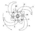
前記耕耘ロータ2は、図9,図10,図11に示すように、車軸1に回り止め状態に嵌合する耕耘軸6をピン7を介して抜け止め装着し、この耕耘軸6に軸芯方向に間隔を隔てて二つの板状のブラケット8A,8Bを固着し、これらブラケット8A,8Bのそれぞれに周方向複数の耕耘爪9をボルト・ナット10を介して固定し、前記耕耘軸6への草などの巻きつきを防止する周方向二つの棒状の巻きつき防止具11をブラケット8A,8B間にわたる状態に取付け、耕耘軸6の先端に、地面に食い込む状態で回転することにより直進安定性を向上するロータディスク12を固着した延長軸13をピン14を介して回り止めかつ抜け止め状態に装着して構成されている。
前記巻きつき防止具11は、回転に伴い内端を外端よりも先行させる姿勢で取り付けられており、その取付け手段は、ブラケット8A,8Bに巻きつき防止具11を挿通させる孔15を形成し、巻きつき防止具11を孔15に挿通させた状態で抜き差し自在なピン16と巻きつき防止具11に固着のフランジ17とを介して抜け止めする手段である。つまり、ピン16を抜くことにより外方に巻きつき防止具11を抜き出すことができるようになっている。
前記ロータディスク12には、前記巻きつき防止具11を外方に抜き出すための操作用の抜き出し孔18が形成されている。
前記延長軸13は、耕耘爪9を浮かした状態で路上走行などを行うための補助車輪19の車軸20を差し込み装着可能に構成されており、補助車輪19を延長軸13に対して軸芯方向で位置決め状態でかつ回り止め状態に取り付ける手段は、延長軸13と車軸20とにわたって固定ピン21を挿通させ、その挿通状態を抜け止めピン22で保持する手段である。また、補助車輪19を延長軸13に対して位置合わせする手段は、図12にも示すように、車軸20に延長軸13の端部に接当することにより車軸20を延長軸13に対して軸芯方向で位置決めする位置決め板23を固着し、この位置決め板23に頭付きピン24を固着し、車軸20の延長軸13に対する周方向位置がずれた状態で頭付きピン24の頭24aを挿通させる孔25と、頭付きピン24の頭24aが孔25に挿通した状態での車軸20の延長軸13に対する回転を許容するように頭付きピン24aの軸部24bを挿通させて延長軸13に形成のピン孔13aと車軸20に形成のピン孔20aとが周方向で一致したとき軸部24bに接当することで車軸20の延長軸13に対する回転を阻止する円弧状の長孔26とをロータディスク12に形成する手段である。つまり、頭24aが孔25に挿通しかつ位置決め板23が延長軸13の端部に接当するように車軸20を延長軸13に差し込み、その状態で軸部24bが長孔26の端部に接当するように車軸20を延長軸13に対して回転させることにより、ピン孔13a,20aを合致させる手段である。なお、長孔26は、左の補助車輪19の右の延長軸13への取付け及び右の補助車輪19の左の延長軸13への取付けを可能にするように、孔25から周方向の両方に延設形成されている。
【0014】
前記ミッションケース3には、後方に延びる変速レバー27で操作される変速装置28と、操縦ハンドル5の左右のハンドル杆5Aのそれぞれに装着した操向レバー29aにより操作されて変速動力の左右の車軸1への伝達を各別に入り切りする左右の操向クラッチ29とが内装されている。
【0015】
前記エンジン4から変速装置28への伝動系は、エンジン4の出力軸4aと変速装置28の入力軸28aとの間にベルトテンション式の走行クラッチ30を設けて構成されている。この走行クラッチ30は伝動を断つ切り状態に付勢されている。
【0016】
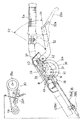
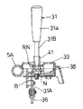
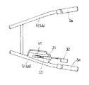
前記走行クラッチ30を操作するための装置、つまり、クラッチ操作装置は、図2〜図8に示すように、一方のハンドル杆5Aに取り付けたブラケットBに、第1左右向き軸芯X1周りで前後に揺動自在な手動クラッチレバー31をその握り操作部31aがハンドル杆5Aよりも上方に突出する状態に取り付けるとともに、ハンドル杆5Aの握り部5aを握った状態で第2左右向き軸芯X2周りで上下に揺動操作される第2手動クラッチレバー32を取り付け、かつ、前記手動クラッチレバー31を指針としてその手動クラッチレバー31の操作位置を表示する表示板33を取り付け、前記手動クラッチレバー31が前方の入り位置P1に位置するとき走行クラッチ30が入り状態となりかつ手動クラッチレバー31が後方の切り位置P2に位置するとき走行クラッチ30が切り状態となるように手動クラッチレバー31と走行クラッチ30のテンションアーム30Aとを連動させる第1連動手段と、前記第2手動クラッチレバー32が下方の入り位置p1に位置するとき手動クラッチレバー31が入り位置P1に位置しかつ第2手動クラッチレバー32が上方の切り位置p2に位置するとき手動クラッチレバー31が切り位置P2に位置するように手動クラッチレバー31と第2手動クラッチレバー32とを連動させる第2連動手段とを設けて構成されている。
すなわち、手動クラッチレバー31を入り位置P1に操作することにより走行クラッチ30を入り状態に切り換え、手動クラッチレバー31を切り位置P2に操作することにより走行クラッチ30を切り状態に切り換え、第2手動クラッチレバー32を入り位置p1に操作することにより手動クラッチレバー31を入り位置P1に揺動させて走行クラッチ30を入り状態に切り換え、第2手動クラッチレバー32を切り位置p2に操作することにより手動クラッチレバー31を切り位置P2に揺動させて走行クラッチ30を切り状態に切り換えるように構成されている。
【0017】
前記第1連動手段は、スプリング34を介してテンションアーム30Aを入り位置に引っ張り操作するレリーズワイヤ35を設け、手動クラッチレバー31の切り位置P2から入り位置P1への揺動に伴いレリーズワイヤ35のインナワイヤ35aを引き操作するようにインナワイヤ35aの端部を手動クラッチレバー31に連係させる湾曲リンク36を設けて構成されている。前記手動クラッチレバー31と湾曲リンク36との枢支連結部37は、手動クラッチレバー31が切り位置P2に位置するときインナワイヤ35aのアウタワイヤ35bからの導出部と第1左右向き軸芯X1とを含む直線Lよりも下方に位置し、手動クラッチレバー31が入り位置P1に位置するとき直線Lの近くで直線Lの上方に位置するように設定されている。つまり、手動クラッチレバー31には、入り位置P1に位置するとき、レリーズワイヤ35を介して入り位置P1を越えて揺動させようとする引き力が作用するようになっている。そして、手動クラッチレバー31に接当することで引き力に抗して手動クラッチレバー31を入り位置P1に保持するストッパー38が設けられている。
【0018】
前記第2連動手段は、手動クラッチレバー31にローラ39を付設し、第2手動クラッチレバー32の入り位置p1から切り位置p2への揺動に伴い手動クラッチレバー31を入り位置P1から切り位置P2に揺動させるとともに第2手動クラッチレバー32の切り位置p2から入り位置p1への揺動に伴い手動クラッチレバー31を切り位置P2から入り位置P1に揺動させるように前記ローラ39に係合する係合部40を第2手動クラッチレバー32に形成して構成されている。前記係合部40は、前記手動クラッチレバー31の揺動に伴って枢支連結部37が前記直線Lに近づくにつれてローラ39を第2左右向き軸芯X2に近づけさせる長孔に形成されている。つまり、第2手動クラッチレバー32の揺動に伴う手動クラッチレバー31の揺動うち、枢支連結部37が直線Lを通過するときの揺動時における第2手動クラッチレバー32の第2左右向き軸芯X2から操作部32aまでの距離L1に対する第2左右向き軸芯X2からローラ39までの距離L2の比を小さくして、枢支連結部37が直線Lを通過するときの揺動に要する操作力を他の箇所での揺動に要する操作力よりも小にするようにしてある。
【0019】
そして、手動クラッチレバー31は、ハンドル杆5Aの上面よりも上方に突出しない状態で第1左右向き軸芯X1周りに揺動自在にハンドル杆5Aに取り付けられた基端部分31Aと、この基端部分31Aに固着のナットNにねじ込み装着した握り操作部31a付き操作杆部分31Bとからなる。つまり、ハンドル杆5Aよりも上方に突出する操作杆部分31Bは着脱自在に構成されている。RNはロックナットである。
【0020】
前記基端部分31Aには、操作杆部分31Bを外した状態で前記表示板33と共同して第2手動クラッチレバー32の操作位置を表示する板状の指針41が取り付けられている。
【0021】
〔別実施形態〕
上記実施の形態では、指針41を別途設けたが、基端部分31を上方に突出するものとしてこれを指針41としても良い。
【0022】
上記実施の形態では、車軸1に耕耘ロータ2を装着した歩行型作業機を示したが、本発明は、ミッションケース3の後部に耕耘ロータなどの作業装置を装着した歩行型作業機にも適用することができる。
【図面の簡単な説明】
【図1】側面図
【図2】クラッチ切り状態の手動クラッチレバー付きクラッチ操作装置の切り欠き側面図
【図3】クラッチ入り状態の手動クラッチレバー付きクラッチ操作装置の切り欠き側面図
【図4】クラッチ切り状態の手動クラッチレバーなしクラッチ操作装置の切り欠き側面図
【図5】クラッチ入り状態の手動クラッチレバーなしクラッチ操作装置の切り欠き側面図
【図6】クラッチ操作装置の縦断面図
【図7】手動クラッチレバーの分解斜視図
【図8】クラッチ操作装置の配置を示す平面図
【図9】耕耘装置の背面図
【図10】耕耘装置要部の分解斜視図
【図11】耕耘装置要部の縦断側面図
【図12】耕耘装置要部の縦断側面図
【符号の説明】
5 操縦ハンドル
5a 握り部
30 走行クラッチ
31 手動クラッチレバー
31B 部分
32 第2手動クラッチレバー
33 表示板
41 指針[0001]
TECHNICAL FIELD OF THE INVENTION
According to the present invention, a manual clutch lever for engaging and disengaging a traveling clutch is attached to a steering handle for a walking worker extending rearward so as to protrude upward from the steering handle, and a grip portion of the steering handle is gripped. A walk-behind working machine such as a management machine having a second manual clutch lever for engaging and disengaging the traveling clutch, and a display plate for displaying the operating position of the manual clutch lever with the manual clutch lever as a guide. A clutch operating device.
[0002]
[Prior art]
This type of walk-behind work machine includes a manual clutch lever that projects upward from the steering handle and has good operability, and a second manual clutch lever that can be operated while holding the grip portion of the steering handle. There is an advantage that operability can be improved by diversifying operation modes for the traveling clutch.
[0003]
Conventionally, as a clutch operating device for a walking-type working machine having such advantages, a manual clutch lever has been permanently provided on a control handle.
[0004]
[Problems to be solved by the invention]
However, according to the above-described conventional technique, when working under a tree such as undergrowth cutting in an orchard, the manual clutch lever protrudes above the steering handle so that the manual clutch lever is protruded from a tree branch. There is a possibility that the traveling clutch may be unexpectedly operated by being hooked.
[0005]
An object of the present invention is to perform a good clutch operation using the manual operation lever and the second manual operation lever at the time of a work in which there is no possibility of the manual clutch lever being caught, but at the time of work under a tree, the traveling clutch may be unexpectedly operated. The point is to surely prevent the cutting operation.
[0006]
[Means for Solving the Problems]
The features, operations and effects of the first invention according to claim 1 are as follows.
[0007]
〔Characteristic〕
A manual clutch lever for engaging and disengaging the traveling clutch is mounted on the steering handle for a walker extending rearward so as to protrude above the steering handle, and the travel clutch is gripped while the grip portion of the steering handle is grasped. A clutch operating device for a walk-behind type working machine, wherein a second manual clutch lever for on / off operation of the manual clutch lever is attached, and a display plate for displaying an operating position of the manual clutch lever is attached using the manual clutch lever as a guide. A portion of the manual clutch lever projecting above the steering handle is detachably configured, and a pointer for displaying an operation position of the second manual clutch lever in cooperation with the display plate is separately provided from the manual clutch lever. The point is that it is provided.
[0008]
[Action]
According to the first aspect of the invention, by removing the upwardly projecting portion of the manual clutch lever, it is possible to prevent the manual clutch lever from projecting above the steering handle. By removing the upwardly projecting portion of the lever, it is possible to prevent the manual clutch lever from being caught on a branch or the like and accidentally disengaging the traveling clutch.
[0009]
In addition, since the second manual clutch lever is provided on the steering handle, the operation of the traveling clutch via the manual clutch lever becomes impossible by removing the upwardly protruding portion of the manual clutch lever. By operating, the traveling clutch can be arbitrarily turned on and off.
[0010]
By the way, the operation position of the manual clutch lever can use the manual clutch lever as a pointer , but in the present invention, a pointer is provided separately from the manual clutch lever, and a display plate for displaying the operation position is provided. The operation position of the second manual clutch lever can also be displayed by providing the manual clutch lever or the operation position of the pointer on the display plate if the manual clutch lever projects above the steering handle. You can know . In addition, a hand that indicates the operation position of the second manual clutch lever in a state where the upwardly protruding portion of the manual clutch lever is removed in cooperation with a display plate for displaying the operation position of the manual clutch lever is referred to as a manual clutch lever. Since it is provided separately, it is possible to know the state of the traveling clutch in a state where the upwardly protruding portion of the manual clutch lever is removed, and it is only necessary to improve only the provision of the pointer.
In addition, since a pointer is provided separately from the manual clutch lever, the pointer performance can be used as a pointer for a function that is considered first.
[0011]
〔effect〕
Therefore, according to the first aspect of the present invention, normally, it is possible to exhibit good clutch operability adapted to the working conditions using the manual clutch lever and the second manual clutch lever, but also to travel while working under a tree. The clutch can be reliably prevented from being accidentally disengaged, and the clutch operability at that time can be favorably maintained with a simple structure.
Further, the operation position of the second manual clutch lever in a state where the upwardly protruding portion of the manual clutch lever is removed can be displayed with good reliability.
[0012]
BEST MODE FOR CARRYING OUT THE INVENTION
As shown in FIGS. 1 and 9, the walking type work machine is configured by assembling an engine 4 and a
[0013]
As shown in FIGS. 9, 10 and 11, the cultivating
The
The
The
[0014]
The
[0015]
The transmission system from the engine 4 to the
[0016]
As shown in FIGS. 2 to 8, a device for operating the traveling
That is, the traveling
[0017]
The first interlocking means is provided with a
[0018]
The second interlocking means attaches a
[0019]
The manual
[0020]
A plate-shaped
[0021]
[Another embodiment]
In the above embodiment, the
[0022]
In the above-described embodiment, the walking type working machine in which the cultivating
[Brief description of the drawings]
FIG. 1 is a side view. FIG. 2 is a cutaway side view of a clutch operating device with a manual clutch lever in a clutch disengaged state. FIG. 3 is a cutaway side view of a clutch operating device with a manual clutch lever in a clutch engaged state. FIG. 5 is a cutaway side view of a clutch operating device without a manual clutch lever in a clutch disengaged state. FIG. 5 is a longitudinal sectional view of a clutch operating device without a manual clutch lever in a clutch engaged state. FIG. 8 is a plan view showing the arrangement of the clutch operating device. FIG. 9 is a rear view of the tilling device. FIG. 10 is an exploded perspective view of the cultivating device. Longitudinal side view of [Figure 12] Longitudinal side view of main part of tillage device
5
Claims (1)
Priority Applications (1)
| Application Number | Priority Date | Filing Date | Title |
|---|---|---|---|
| JP34255197A JP3599545B2 (en) | 1997-12-12 | 1997-12-12 | Clutch operating device for walking type working machine |
Applications Claiming Priority (1)
| Application Number | Priority Date | Filing Date | Title |
|---|---|---|---|
| JP34255197A JP3599545B2 (en) | 1997-12-12 | 1997-12-12 | Clutch operating device for walking type working machine |
Publications (2)
| Publication Number | Publication Date |
|---|---|
| JPH11170884A JPH11170884A (en) | 1999-06-29 |
| JP3599545B2 true JP3599545B2 (en) | 2004-12-08 |
Family
ID=18354635
Family Applications (1)
| Application Number | Title | Priority Date | Filing Date |
|---|---|---|---|
| JP34255197A Expired - Lifetime JP3599545B2 (en) | 1997-12-12 | 1997-12-12 | Clutch operating device for walking type working machine |
Country Status (1)
| Country | Link |
|---|---|
| JP (1) | JP3599545B2 (en) |
-
1997
- 1997-12-12 JP JP34255197A patent/JP3599545B2/en not_active Expired - Lifetime
Also Published As
| Publication number | Publication date |
|---|---|
| JPH11170884A (en) | 1999-06-29 |
Similar Documents
| Publication | Publication Date | Title |
|---|---|---|
| JP3599545B2 (en) | Clutch operating device for walking type working machine | |
| EP2412591B1 (en) | Work vehicle brake | |
| JP2019004843A (en) | Walking-type working machine | |
| EP1430764A1 (en) | Independent, positive, reverse drive mower with brake lockout | |
| JP2009299576A (en) | Working machine | |
| JP2003072412A (en) | Walking type working vehicle | |
| JP4052606B2 (en) | Hand tractor | |
| JP5111942B2 (en) | Walking type work machine | |
| JP3356379B2 (en) | Operating device for walking type work vehicle | |
| JPH0678601A (en) | Apparatus for attaching tilling tine | |
| JP3743946B2 (en) | Rotary tiller | |
| JP5289689B2 (en) | Walking type management machine | |
| JP5043703B2 (en) | Walking type work machine | |
| JPS6024646Y2 (en) | Interlocking structure between rotating handle and tilling clutch lever in walk-behind tiller | |
| JP3234502B2 (en) | Operation structure of walking type work vehicle | |
| JP3718545B2 (en) | Control gear reverse shift control device | |
| JP2002213489A (en) | Clutch operation device of work vehicle | |
| JPS5928913Y2 (en) | Tiller power transmission device | |
| JPH08324281A (en) | Speed change panel installing device in movable agricultural machine | |
| JPS632914Y2 (en) | ||
| JPH1052101A (en) | Ambulatory agricultural machine stand device | |
| US1381104A (en) | Tractor-clutch control | |
| JP2002337760A (en) | Engine device of pedestrian-controlled moving agricultural machinery | |
| JP2008296779A (en) | Walking type working machine | |
| JPH1047214A (en) | Walking type work vehicle |
Legal Events
| Date | Code | Title | Description |
|---|---|---|---|
| A977 | Report on retrieval |
Free format text: JAPANESE INTERMEDIATE CODE: A971007 Effective date: 20040130 |
|
| A131 | Notification of reasons for refusal |
Free format text: JAPANESE INTERMEDIATE CODE: A131 Effective date: 20040325 |
|
| A521 | Written amendment |
Free format text: JAPANESE INTERMEDIATE CODE: A523 Effective date: 20040518 |
|
| TRDD | Decision of grant or rejection written | ||
| A01 | Written decision to grant a patent or to grant a registration (utility model) |
Free format text: JAPANESE INTERMEDIATE CODE: A01 Effective date: 20040826 |
|
| A61 | First payment of annual fees (during grant procedure) |
Free format text: JAPANESE INTERMEDIATE CODE: A61 Effective date: 20040914 |
|
| R150 | Certificate of patent or registration of utility model |
Free format text: JAPANESE INTERMEDIATE CODE: R150 |
|
| FPAY | Renewal fee payment (event date is renewal date of database) |
Free format text: PAYMENT UNTIL: 20090924 Year of fee payment: 5 |
|
| FPAY | Renewal fee payment (event date is renewal date of database) |
Free format text: PAYMENT UNTIL: 20090924 Year of fee payment: 5 |
|
| FPAY | Renewal fee payment (event date is renewal date of database) |
Free format text: PAYMENT UNTIL: 20100924 Year of fee payment: 6 |
|
| FPAY | Renewal fee payment (event date is renewal date of database) |
Free format text: PAYMENT UNTIL: 20110924 Year of fee payment: 7 |
|
| FPAY | Renewal fee payment (event date is renewal date of database) |
Free format text: PAYMENT UNTIL: 20120924 Year of fee payment: 8 |