JP3596339B2 - Inter-vehicle distance measurement device - Google Patents
Inter-vehicle distance measurement device Download PDFInfo
- Publication number
- JP3596339B2 JP3596339B2 JP6839099A JP6839099A JP3596339B2 JP 3596339 B2 JP3596339 B2 JP 3596339B2 JP 6839099 A JP6839099 A JP 6839099A JP 6839099 A JP6839099 A JP 6839099A JP 3596339 B2 JP3596339 B2 JP 3596339B2
- Authority
- JP
- Japan
- Prior art keywords
- distance
- vehicle
- edge
- inter
- image
- Prior art date
- Legal status (The legal status is an assumption and is not a legal conclusion. Google has not performed a legal analysis and makes no representation as to the accuracy of the status listed.)
- Expired - Fee Related
Links
Images
Landscapes
- Length Measuring Devices By Optical Means (AREA)
- Measurement Of Optical Distance (AREA)
- Image Processing (AREA)
- Optical Radar Systems And Details Thereof (AREA)
- Image Analysis (AREA)
Description
【0001】
【発明の属する技術分野】
この発明は、追従中の先行車の車間距離および車間距離変化計測の確実性を向上させる技術に関する。
【0002】
【従来の技術】
従来の車間距離計測装置としては、例えば、特開平8−278126号公報に記載されたものがある。この装置では、縦に並べたステレオ画像から水平エッジのヒストグラムを抽出し、それらのヒストグラムのピークを、垂直方向をy軸としたときに、y軸の下側より順に探索し、ヒストグラムのピークのy軸上におけるステレオ画像間の位置の差を先行車の視差として、車間距離を求めるものである。
【0003】
【発明が解決しようとする課題】
しかし、上記従来の装置では、先行車までの車間距離測定に用いるデータとして水平エッジのヒストグラムだけを用いているため、その水平エッジ成分が先行車のエッジであるか否かの判断が不十分であり、車両以外のエッジを用いて対応点探索を行なってしまう可能性があるという問題があった。特に、歩道橋や停止線など路面上にかかる長く強い横エッジが複数あると、それらのエッジの方が先行車よりも強調されるため、先行車以外のエッジまでの距離を算出してしまう可能性が高くなる。また、距離の算出をステレオ視差からの演算だけで行っているため、分解能が粗く、かつ、他手法との照合がないため、ステレオマッチングが原因となる距離の誤計測を判断することができない、という問題があった。
【0004】
本発明は上記のごとき従来技術の問題を解決するためになされたものであり、車間距離計測における先行車との車間距離の計測の確実性を向上させた車間距離計測装置を提供することを目的とする。
【0005】
【課題を解決するための手段】
上記の目的を達成するため、本発明においては、特許請求の範囲に記載するように構成している。まず、請求項1に記載の発明においては、車両に搭載され、路面に平行方向と垂直方向の2次元的に光を走査して照射し、照射した方向毎の光の反射強度と、その光の反射面までの距離とを計測する光測距装置と、
前記計測した反射強度の各角度毎の値をデジタル値の配列とした輝度画像と、前記計測した距離の各角度毎の値を前記輝度画像に対応する順序でデジタル値の配列とした距離画像とを記憶するメモリと、
前記光測距装置の走査の中心軸と光軸が平行になる位置および姿勢で車両に搭載された電子式のカメラと、
前記距離画像に基づいて先行車までの車間距離を計測し、かつ、前記距離画像上において先行車が計測された位置に基づいて前記カメラの画像上で先行車が存在する位置を求める距離・位置演算手段と、
前記距離・位置演算手段で求めた位置と距離に基づいて、前記カメラの画像上に撮像された先行車の左右上下端を含む程度の縦長のウィンドウを複数設定するウィンドウ設定手段と、
前記複数の全てのウィンドウにおいて縦長のウィンドウでは各y座標毎の水平エッジのヒストグラムを求めるヒストグラム演算手段と、
前記複数のウインドウにおいて同じy座標上に検出される前記ヒストグラム演算手段により求められたヒストグラムのピーク値である水平エッジのy座標位置を検出するエッジ検出手段と、
前記エッジ検出手段により求められた複数のウィンドウにおいて同じy座標上に検出されるヒストグラムのピーク値である水平エッジの移動ベクトルを計測するベクトル計測手段と、
前記距離画像から求めた車間距離の変化と適合する方向および大きさの移動ベクトルを示すエッジだけを先行車のエッジとして選択するエッジ選択手段と、
前記エッジ選択手段で求めた先行車上のエッジの中から2本ずつを1つの組として複数組選択し、それらの組におけるそれぞれのエッジ間距離を求め、同じ組について二つの時点で求めたエッジ間距離の比、すなわちエッジ間距離の時間的な変化率が同じ値となる組が最も多い組のエッジを先行車上のエッジと再確認する先行車エッジ判断手段と、
前記先行車上のエッジと再確認されたものについてのエッジ間距離の変化率に基づいて車間距離の変化率を求める車間距離変化率演算手段と、
前記距離・位置演算手段で求めた車間距離の所定回数前の演算値に前記車間距離の変化率を乗算することによって車間距離を算出する車間距離算出手段と、
を備えるように構成している。
上記のように、請求項1においては、光測距装置と、前記光測距装置の走査の中心軸と光軸が平行になる位置および姿勢で搭載された電子式のカメラとの両方を用い、光測距装置の輝度画像とカメラの画像とを組み合わせて車間距離を算出するように構成し、かつ、ウィンドウ設定手段は、縦長のウィンドウを設定するように構成している。
【0006】
また、請求項2に記載の発明は、請求項1と同様の構成において、ウィンドウ設定手段は、横長のウィンドウを設定し、エッジ検出手段は、同じx座標上に検出されるヒストグラムのピーク値である垂直エッジのx座標位置を検出するように構成したものである。
【0008】
また、前記先行車エッジ判断手段では、前記の求めた先行車上のエッジの中から2本ずつを1つの組として複数組選択し、それらの組におけるそれぞれのエッジ間距離を求め、同じ組について二つの時点で求めたエッジ間距離の比、すなわちエッジ間距離の時間的な変化率が同じ値となる組が最も多い組のエッジを先行車上のエッジと再確認するように構成している。例えば10本のエッジを2本ずつa組、b組、c組、d組、e組の5組に分けた場合、a〜dの4組では変化率の値がαで、e組のみはβであったとすれば、変化率が同じ値となる組が最も多いa〜d組のエッジが先行車上のエッジであり、e組のエッジは先行車上ではない他のエッジであると判断する。
【0009】
また、前記車間距離変化率演算手段では、前記先行車上のエッジと判断されたものについてのエッジ間距離の変化率に基づいて車間距離の変化率を求めるように構成している。具体的には、エッジ間距離の変化率の逆数が車間距離の変化率となる。
【0010】
また、前記車間距離算出手段では、前記距離・位置演算手段で求めた車間距離の所定回数前の演算値に前記車間距離の変化率を乗算することによって車間距離を算出するように構成している。
【0011】
また、請求項3に記載の発明においては、前記距離・位置演算手段で求めた車間距離と前記車間距離の変化率から求めた車間距離とを照合することにより車間距離演算の確認を行なうように構成している。
【0012】
また、請求項4に記載の発明において、前記距離・位置演算手段は、前記先行車エッジ判断手段で先行車以外のエッジと判断された位置に対する計測値は用いずに、距離と位置の演算処理を行なうように構成している。
【0013】
また、請求項5に記載の発明においては、請求項1または請求項2において、前記光測距装置の輝度画像の値の低い位置の計測値は用いずに、前記距離・位置演算手段における距離と位置の演算処理を行なうように構成している。
【0014】
【発明の効果】
請求項1および請求項2においては、レーザレンジファインダのような光測距装置とカメラとを組み合わせることにより、信頼性を確保するために光測距装置の距離分解能を粗くした場合でも、距離精度を保持または向上することが可能となり、同様に、装置の信頼性確保のために走査を遅くして計測の時間間隔を長くした場合においても、カメラを1台追加した構成にしただけで、距離測定のレスポンスを遅くすることなく、通常の画像処理の速度での距離計測が可能となる、という効果が得られる。
【0017】
また、請求項1および請求項2においては、エッジ間距離の時間的な変化率を求め、変化率の同じエッジを先行車のエッジと判断する(変化率の異なるエッジは先行車以外のエッジとして除去する)ように構成しているので、先行車上にかかる光のノイズなどの除去が可能になり、より確実に先行車を構成するエッジだけを選択することが可能となる。さらに、上記のように先行車以外のエッジを除外することにより、除外したエッジの位置を車間距離算出の際に除外することができるので、路面表示など先行車周囲にエッジが多く存在する環境や光の位置などによってノイズの多い環境下でも、環境変化に影響されず確実性の高い車間距離計測が可能となる。
【0018】
また、請求項1および請求項2においては、先行車上のエッジと判断されたエッジについてのエッジ間距離の変化率から車間距離の変化率を求めるように構成したことにより、光のノイズや影など、多少のエッジ検出ミスがある場合、および先行車上のエッジを検出しにくい環境下でも、車間距離の変化率を確実に正しく求めることが可能となる。
【0019】
また、請求項1および請求項2においては、距離・位置演算手段で求めた車間距離の所定回数前の演算値に車間距離の変化率を乗算することによって車間距離を算出することにより、視差や距離画像から求める車間距離よりも高精度に車間距離を計測することが出来る。特に光測距装置とカメラとを組み合わせた構成に適用した場合には、光測距装置の計測間隔が長い場合でも、カメラの撮像間隔での車間距離の更新が可能となる。更に、光測距装置の距離分解能が粗い場合には、距離の高精度化も可能となる。
【0020】
また、請求項3においては、距離・位置演算手段で視差や距離画像から求めた車間距離と車間距離の変化率から求めた車間距離とを照合することにより、二つの方法で求めた車間距離の正確性の確認を行なうことが出来るので、より確実性の高い車間距離計測を行なうことが出来る。
【0021】
また、請求項4において、前記距離・位置演算手段は、先行車エッジ判断手段で先行車以外のエッジと判断された位置に対する計測値は用いずに、距離と位置の演算処理を行なうことにより、距離と位置の演算における確実性を向上させることが出来る。例えば、先行車以外のエッジと判断された位置におけるレーザレンジファインダで計測した距離画像上の値を、車間距離計測の際の判断に反映させない構成なので、ノイズなどによる誤計測値を除去でき、より正確な測距が可能となる。
【0022】
また、請求項5においては、請求項1または請求項2において、距離画像からの車間距離計測の際に、光測距装置の輝度画像上の反射強度が低い位置で計測された距離を反映させない構成としたため、誤計測値を除去でき、さらに信頼度の高い計測値だけを用いた、より正確な測距が可能となる。
【0023】
【発明の実施の形態】
(第1の実施の形態)
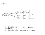
図1は本発明の第1の実施の形態の構成を示すブロック図である。
図1において、1および2は電子式のカメラであり、自車の前部に前方を向いて設置されており、両カメラの光軸は相互に平行で、かつ撮像面の垂直軸が同じライン上に揃うように設置されている。なお、撮像面の水平軸が同じライン上に揃うように設置してもよい。また、車両の後部に後方を向けて設置し、車両後方の障害物を検出するように構成することもできる。3、4はそれぞれカメラ1、2から入力した画像信号を記憶する画像メモリである。5は演算部であり、例えばCPU、RAM、ROM等からなるマイクロコンピュータで構成される。6は自車の前方に存在する障害物等の検出対象物であり、図1では先行車を例示している。
【0024】
以下、まず第1の実施の形態に用いる種々の演算手段と方法について説明し、それからフローチャートに基づいて全体の演算の流れを説明する。
図2は、ステレオ画像を用いて三角測量の原理でカメラから検出対象までの距離を求める原理を説明する図である。図2においては、カメラA(前記カメラ1に相当)で撮像した画像を画像A、カメラB(前記カメラ2に相当)で撮像した画像を画像Bで示し、検出対象の位置を点p(x,y,z)としている。
【0025】
図2から判るように、焦点距離f、眼間距離(両カメラ間の距離)Dが既知であり、光軸が互いに平行な2台のカメラA、Bで撮像したステレオ画像において、2枚の画像間のマッチング位置ya、ybを求めることできれば、カメラから対象物pまでの距離Zは下記(数1)式より求めることができる。
【0026】
Z=f・D/(ya−yb)=f・D/S …(数1)
ただし、ya−yb=Sは視差であり、図2のように、光軸が平行で、所定間隔を隔てて設置された二つのカメラA、Bで一つの物体を撮像した場合に、それぞれのカメラに写った画像の位置の差、すなわち画像Aにおける位置yaと画像Bにおける位置ybとの差である。なお、この例では、眼間距離Dと距離Zの単位はm、焦点距離f、視差Sおよび位置ya、ybの単位は画素である。例えばカメラA、BはCCDを用いたものであり、画素数を640×480とした場合、1画素の大きさは10μm程度である。
【0027】
上記(数1)式は、両カメラの光軸が相互に平行で、かつ撮像面の垂直軸が同じライン上に揃うように設置した場合であるが、撮像面の水平軸が同じライン上に揃うように設置した場合には、下記(数1’)式に示すようになる。
Z=f・D/(xa−xb)=f・D/S …(数1’)
ただし、xa−xb=Sは視差
なお、以後の説明は全て撮像面の垂直軸が同じライン上に揃うように設置した場合を例として説明する。
【0028】
上記の視差Sを検出するには、一方の画像(例えば画像A)上において点pが撮像されている点(xa、ya)に対応する他方の画像(例えば画像B)上の点(xb、yb)を検出する必要がある。その方法としては、画像A上の点(xa、ya)を含む或る範囲の画像(ウィンドウ)と最も類似した範囲を画像B内から探すことで求めることができる。この類似度の算出には、画像間の差分法や正規化相関法などがある。そして距離画像(ウィンドウ毎にその内部に撮像される物体までの視差を求めた画像)は、定義した全てのウィンドウにおいて差分法や正規化相関法により、他方と類似度の高いウィンドウが存在する位置を求めることで作成できる。
【0029】
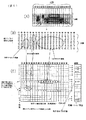
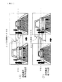
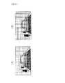
図3は、両画像の対応する位置毎の視差を求めた結果を示す図であり、詳しくは、道路前方を撮像した画像において、一方の画像(例えば画像B)をウィンドウ毎に切り、その全てのウィンドウにおいて他方の画像(例えば画像A)からそのウィンドウと最も類似度の高い画像の位置を求めることで、両画像における対応する位置を検出し、それぞれの対応する位置から各ウィンドウ毎の視差を求めた結果を表したものである。図3において、(A)は下画像(画像Aに相当)、(B)は上画像(画像Bに相当)、(C)は視差の表、(D)は視差が「15」のウィンドウ部分のみを抜き出した画像を示す。また、図3(B)、(C)の(1)〜(20)は各ウィンドウの水平方向(以下、横方向と記す)の位置を示す。ただし、図においては(1)〜(20)を丸付き数字で表している。また、一つのウィンドウは幅(x方向の長さ)がxw、高さ(y方向の長さ)がywである。
上記のように、各ウィンドウ毎の視差が判れば、前記(数1)式を用いることによって、該当するウィンドウに撮像されている物体までの距離を求めることが出来る。
【0030】
以下、図3(C)のようにウィンドウ毎にその内部に撮像されている物体までの視差を求めた画像を“距離画像”と呼ぶことにする。このウィンドウ毎に算出される視差は、当該ウィンドウの内部に撮像されていてエッジ(画像が明から暗または暗から明に変化する点が連続した部分で、画像の端などを示す線分に相当する)などの特徴的な部分を持つ物体までの距離に相当するから、一つの対象物が複数ウィンドウに跨って撮像されていると、隣接するウィンドウで同じ視差が求められる。例えば、道路前方を撮像した画像における距離画像の場合、先行車と、先行車が存在する真下の路面とは同距離なので、図3(D)に太線のウィンドウで示すように、先行車の下部と同じy座標上にあるウィンドウは先行車と同じ視差で算出される。例えば図3(C)の下から2行目に「15」が横方向に連続しているのが上記の部分に相当する。なお、図3(C)において、中央部分に視差「15」が集合している部分が先行車に相当し、(3)、(4)列に視差「19」が集合している部分が「左方の木」に相当し、(6)列に視差「5」が連続している部分が「中央の木」に相当する。
【0031】
上記のように、距離画像は前方に高さのある物体が存在すると、その物体が撮像されているx座標位置のウィンドウでは同じ視差が検出される。一方、車両横にある白線部分のように路面などの高さを持たない位置では、同じx座標上で同じ視差が検出されるウィンドウは一つである。すなわち、前方に物体が存在する場合、同一x座標の方向でのウィンドウにおいて同じ視差の個数を数えることにより、物体を検知することができる。この方法によれば、複数の物体も一つの物体も同じ方法で検出することができ、検出対象や背景の色に左右されずに物体を検知できるようになる。また、白線や停止線などの路面表示は、同じ視差を示すウィンドウが同じ方向に現れないため、路面表示と高さをもつ障害物とを誤検出することがなくなるという利点もある。加えて、距離画像だけを利用しているため、検出対象の色や形状および背景色にかかわらず同様の処理で複数物体を検出できる。
【0032】
図4は、距離画像上の或るウィンドウで求めた視差とそのウィンドウの横方向の位置に基づいて、対応する表中の位置に投票する様子を表した図であり、(A)は右画像、(B)は視差の表、(C)は投票用の表を示す。なお、この場合における「投票」とは、或る横方向位置とそれに対応する視差の値の位置に、+1ずつ加算することを意味する。例えば位置(8)の位置に視差「15」が1個存在する場合には、図4(C)の位置(8)で視差「15」の位置に「+1」が加算される。図4(B)の例では、位置(8)の位置に視差「15」が5個存在するから、最終的には位置(8)で視差「15」の位置に「5」が投票されることになる。
【0033】
また、図5は、上記の投票を全てのウィンドウにおいて行った結果を示す図であり、(A)は上画像、(B)は視差の表、(C)は投票用の表を示す。
【0034】
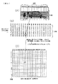
図4から判るように、図3で設定したウィンドウにおいて、横方向が同じ位置のウィンドウは同じ方向を撮像したものである。また、図5から判るように、前方に物体が存在する場合、物体を検知している部分では同じx座標上の縦方向のウィンドウは同じ視差が求められ、路面上に物体が存在しない場合では同じy座標上の横方向のウィンドウで同じ視差が求められる。このような距離画像を用いて、図4に示した方法で表に投票を行なうと、同じ方向(同じx座標上)に同じ視差が並んでいると、その方向と視差の値への投票回数が多くなるため、その位置の値が高くなる。したがって、図5の表から値の高い位置を探すことで前方の物体の有無を検知できる。図5に示す例では、(3)、(4)番目のウィンドウで視差「19」の部分(左方の木に相当)、(5)番目のウィンドウで視差「5」の部分(中央の木に相当)、(8)〜(16)番目のウィンドウで視差「15」の部分(先行車に相当)で投票が集中し、値が高くなっている。例えば視差「15」の部分の値が高いということは、カメラが撮像した画角内に視差が約15画素となる物体が撮像されていることを示す。仮に前記図2に示した眼間距離Dを0.1m、焦点距離fを1500画素とすると、カメラからその物体までの距離は、前記(数1)式により、前方10m(=1500×0.1/15)であると求められる。また、視差が15画素の位置の投票結果をx軸方向で見ると、x軸方向に定義した(8)〜(16)番目のウィンドウ付近の値が高く、その左右両側のウィンドウでは投票値が低くなっている。
【0035】
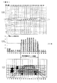
図6は、上記の内容を判りやすく示すため、図5の投票結果から視差15の部分を抜き出して1次元グラフとしてあらわした図である。図6において、(a)は図5の(c)に相当する表、(b)は1次元グラフ、(c)は対応する画像である。以下、図6を用いて、物体が撮像されるおおよその横方向(x軸方向)の範囲を求める方法を説明する。
【0036】
図6(b)において、横軸はx方向に定義したウィンドウの位置、縦軸はそのx座標位置で視差=15となったウィンドウの個数である。この図では、(8)〜(16)番目の値が高い。このことは(8)〜(16)番目の間に高さをもつ物体が撮像されていることを示している。また、グラフ内の横線は、物体が撮像されているか否かを判断するために設けたしきい値である。しきい値は、例えば次の方法で設定すればよい。すなわち、表の値は画像上に撮像される物体の高さに比例し、画像上の物体の高さは実際の物体の高さを一定とすると物体までの距離に反比例する。このことから、物体までの距離に応じて画像上の高さを計算し、その高さに含まれるウィンドウの個数を基準にヒストグラムのしきい値を設定することができる。例えば、図6(b)では、しきい値を5.5に設定している。したがって、しきい値以上の値を持つ位置は(8)〜(16)番目のウィンドウであるので、前方の物体が撮像されるおおよその横方向の範囲は(8)〜(16)番目のウィンドウの間であると求められる。上記のように先行車が撮像されている横方向の範囲をxl〜xrとする。
【0037】
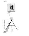
次に、図7は、一方の画像に撮像された先行車の上下端の撮像された位置と先行車までの距離の関係を表す図であり、(A)は側面図、(B)は撮像面Aの画像例である。
先行車までの距離Zが分かっている場合、路面からカメラまでの高さをH、先行車の高さをhとすると、図7より、その先行車の上下端(yu,yd)は、ほぼ、下記(数2)式の位置に撮像される。なお、ここでは下端ydはほぼ路面と同じ高さとみなす。
【0038】
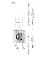
yu=f×(h−H)/Z, yd=−f×H/Z …(数2)
図8は、先行車上に上記の上下端(yu、yd)を含む程度の大きさで縦長のウィンドウを切り、それぞれにおいて各y座標毎に水平エッジのヒストグラムと輝度のヒストグラムを求めた様子を示す図であり、(A)は原画像上に設けた縦長のウィンドウの一例、(B)は先行車の存在位置を水平微分したエッジを示す図、(C)は(B)における▲1▼〜▲5▼のウィンドウの各水平エッジのヒストグラムを示す。なお、横長のウィンドウを設定した場合には、各x座標毎の垂直エッジのヒストグラムを求める。
【0039】
これらの縦長のウィンドウを定義する横方向の位置は、前記図6の距離画像から検出した先行車が撮像される範囲xl〜xrの間とすればよい。また、ウィンドウを定義する縦方向の位置は、前記(数2)式で求めた値をもとに、上下端yu、ydが含まれる程度の大きさ(上がyu+α、下がyd−α ただしαは所定の余裕値)とする。このとき、(数2)式の先行車の高さhは、通常、未知の値であるが、一般的な車両の高さを考え、1〜2m程度の範囲の適度な値で十分である。
【0040】
先行車は長い横エッジをもつ。そのため、先行車上にウィンドウを定義すると、図8の中央部の▲2▼▲3▼▲4▼の3個所に定義したウィンドウでは、その水平エッジのヒストグラムのピークがほぼ同じ位置に現われる。ここでは、距離画像と(数2)式より、先行車が存在し得る付近に限定してウィンドウを設けているため、定義したウィンドウにおいてウィンドウ間で同じ位置にヒストグラムのピークが存在する位置(ye1〜ye5の位置)は先行車上のエッジであると判断できる。
【0041】
次に、図8の方法で検出したエッジの移動ベクトルを求め、そのエッジの中から、先行車の動きに基づいた動きをするエッジだけを選択する。
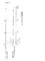
図9はエッジの移動ベクトルを示す図であり、(A)は先行車が遠ざかる(車間距離が大きくなる)場合の例、(B)は先行車が近づく(車間距離が小さくなる)場合の例を示す。図9に示すように、先行車上のエッジは、車間距離が大きくなる場合にはy軸方向に画像の中心(原点を画像の中心とするとy=0の位置)に向かって移動し、車間距離が短くなる場合は画像の中心から遠ざかる方向に移動する。したがって、図8の方法で検出したエッジが先行車上のエッジであれば、車間距離が大きくなる場合は、y>0の位置のエッジは下方、y<0の位置のエッジは上方に移動し、車間距離が短くなる場合は、y>0の位置のエッジは上方、y<0の位置のエッジは下方に移動し、車間距離が一定の場合はエッジの位置は不変となる。なお、図9に上下方向の矢印で示したのが移動ベクトルである。
【0042】
また、そのエッジの移動量は、原点から遠いほど大きく、原点から近いエッジほど小さい。これらのことから、ステレオ画像処理で車間距離の変化を求めるとともに、図8で検出したエッジの移動ベクトルを求め、そのベクトルが図9に示す理論どおりの動きをするものを車両上のエッジとして再確認することにより、先行車検出の精度を向上させることが出来る。例えば、先行車直後の路面表示や先行車前方の歩道橋などのような車両以外のエッジは、上記の処理により誤検出エッジとして除去することができる。
【0043】
次に、エッジ間距離の変化率を求める方法およびその結果を用いて先行車上のエッジを再確認する方法について説明する。
図10は、一方の画像に撮像された先行車の上下端の撮像された位置と先行車までの距離の関係を表す図であり、(A)は時点t−1における位置、(B)は時点tにおける位置を示す。
図10に示すように、追従中の車両上から、バンパーなど路面に平行な線を異なる位置から2本ずつ2組選択し、その2本の平行線間の距離をh1、h2とする。焦点距離をfとし、時点t−1において車間距離がZt−1のときのh1、h2の画像上の長さをそれぞれy1t,y2tとすると、y1t,y2tは、それぞれ下記(数3)式で示される。
【0044】
y1t−1=h1・f/Zt−1, y2t=h2・f/Zt−1 …(数3)
また、時点tにおける車間距離をZtとすると、同様に、そのときの画像上のh1,h2の長さは、y1t=h1・f/Zt, y2t=h2・f/Ztとなる。これらから、車間距離がZtからZt−1に変化したときの画像上のエッジ間の長さの時間的な変化率(以下、単に変化率と記す)は、h1、h2ともに、下記(数4)式に示すようになる。
【0045】
y1t/y1t−1=y2t/y2t−1=Zt−1/Zt …(数4)
上記(数4)式から判るように、エッジ間距離に関わらず、同じ物体上のエッジ間距離の変化率は、どのエッジが選択された場合でも値が同じになり、その値は、車間距離の変化率(Zt/Zt−1)の逆数(Zt−1/Zt)となる。
このことから、図8や図9の方法によって検出した画像上の車両のエッジから2本ずつの組を作り、二つの時点で計測したエッジ間距離から、それらのエッジ間距離の変化率(y1t/yt−1,y2・/y2t−1、…、ynt・/ynt−1)を求め、それぞれの組で求めたエッジ間距離の変化率から、その値が同じである最も多い組のエッジを先行車上のエッジであると再確認することができる。
【0046】
また、同時に、その最も多くの個所で求められたエッジ間距離の変化率は、その時点での画像上の先行車の大きさの変化率となる。さらに、或るエッジを含む組に限って変化率が常に異なるものがあれば、そのエッジを先行車以外のエッジとして除外できる。これにより、先行車付近の路面表示や路面のノイズだけでなく、外部からの反射光など、先行車上に現れるが先行車以外の水平エッジとなる光のノイズなども、先行車以外のエッジとして除去することが可能となる。
【0047】
このような除外すべきエッジがある場合、距離画像上におけるそのエッジの存在位置の視差の値は、誤った値となる。このことから、距離画像を用いた距離計測において、除外すべきエッジと判断されたエッジの存在位置の視差を用いないようにすることで、車間距離計測の確実性を向上させることができる。
上記のように、図9、図10のような判断で先行車上のエッジだけを確実に選択することは、距離計測の確実性増加に対して有効な手段であり、特に、光のノイズや周囲のノイズなど、先行車以外のエッジが多く検出される環境下での距離計測の確実性向上に有効である。
【0048】
次に、上記図9、図10で説明した方法を利用して車間距離の変化率を求める方法について説明する。
図9、図10で求めたエッジ間距離の変化率は、前記(数4)式に示したように距離の変化の逆数となる。このことから、最も多くのエッジについて求められたエッジ間距離の変化率の逆数をその時点での車間距離の変化率とすることができる。この方法では、先行車上のエッジを2本だけでなく、ヒストグラムのピークにより、できるだけ多くの本数求めているため、光の反射などにより、或る一部のエッジが検出されない場合でも、他のエッジが検出できれば、その影響をうけることなく車間距離の変化率を求めることができる。この判断を加えることは、先行車上のエッジを検出しにくい環境に対する安定した確実な距離変化の算出に有効な手段となる。
【0049】
次に、車間距離計測について説明する。車間距離計測には次の3方法がある。
(1)連続的に入力される画像を用いたステレオ画像処理では、先行車上の視差を用いて前記(数1)式を適用することにより、先行車までの車間距離を時間的に連続的に求めることができる。
(2)車両追従中における車間距離の変化率は、前記図9、図10で説明した方法で求めることができる。したがって、同じ車両に追従中であれば、数回前にステレオ画像処理で視差から計測した車間距離Zt−1に数回前からの画像上の車両のエッジ間距離の変化率の逆数を乗算することによっても、その時点での車間距離を算出することができる。
(3)画像上の先行車の高さ(yu−yd)から車間距離を求める方法。
【0050】
以下、上記(3)の方法について詳細に説明する。図7に示した先行車の高さhは通常は未知の値である。しかし、ステレオ画像処理で求めた先行車までの距離Zと画像上の先行車の高さ(yu−yd)が求められていれば、下記(数5)式によって追従中の車両の高さhを求めることができる。
【0051】
h=Z×(yut−ydt)/f …(数5)
ただし、f:焦点距離
yut:時点tにおけるyuの値
ydt:時点tにおけるydの値
ここでは、図8、図9、図10の方法で、確実性高く先行車のエッジだけを検出できているため、画像上から検出した先行車上のエッジの組み合わせのうち、最上端と最下端のエッジを選択することで、画像上の先行車の高さ(yu−yd)を求めることが可能である。追従中の先行車の高さhは一定であるので、同じ車両に追従中の場合、1度先行車の高さhを求めておけば、そのhをもとに新たに検出した画像上の先行車の高さ(yut+1−ydt+1)を、(数5)式に代入することで、下記(数6)式に示すように、画像上の先行車の高さ(先行車上のエッジ間の距離)からも車間距離Zを算出することが出来る。
【0052】
Z=h・f/(yut+1−ydt+1) …(数6)
ただし、h:(数5)式で算出した値
(数5)式のhを(数6)式に代入すると下記(数6’)式のようになる。
【0053】
Zt+1=Zt×(yut−ydt)/(yut+1−ydt+1)
或いは …(数6’)
Zt=Zt−1×(yut−1−ydt−1)/(yut−ydt)
ただし、Zt+1:時点t+1における車間距離
Zt:時点tにおける車間距離
Zt−1:時点t−1における車間距離
yut−1:時点t−1におけるyuの値
ydt−1:時点t−1におけるydの値
(数6’)式から判るように、上記の方法で求めた車間距離は、ステレオで求めた時点tにおける車間距離Ztに対して、画像上のエッジ間距離の変化率の逆数(yut−ydt)/(yut+1−ydt+1)を乗算することと同じである。つまり、(2)と(3)の方法は、実際に適用する計算式は異なっているが、原理的には同じことである。
【0054】
上記(2)、(3)の距離計測方法は、距離の確認および距離計測を高精度化することが出来る。すなわち、距離の確認は、(1)のステレオ画像処理で算出した距離と(2)または(3)のエッジ間距離の変化率から求めた距離とを照合することによって行なうことが出来る。また、エッジ間距離の変化率から求める車間距離変化率は、ステレオ画像処理で連続的に求めた距離から算出される車間距離変化率より精度が良い。
【0055】
ここで、上記の精度向上の理由について図11に基づいて説明する。
(1)の方法と(2)、(3)の方法で求めた車間距離の精度の違いを考える。車載のステレオカメラの場合、h>D(h:先行車の高さ、D:カメラ間の距離)であるため、同じ車間距離を計測したときにおける視差(ya−yb)(単位:画素)に対して先行車の高さ(yu−yd)(単位:画素)の方が大きな値となる。そのため、(数6)式による車間距離計測の方が、1画素のずれによる誤差の影響が小さいため、ステレオ視差からの計測車間距離より分解能の細かい測距が可能となる。
【0056】
例えば、眼間距離D=0.2m、f=1000画素、先行車の高さh=1mとした場合において、車間距離が10mの場合を考える。このとき、先行車のステレオ視差は20画素(=0.2×1000/10)、画像上の先行車の高さは100画素(=1×1000/10)となる。この二つにおいて、視差と先行車の高さ検出が1画素ずれると、ステレオ視差の場合には、20画素が19画素となるので、10.52m(=0.2×1000/19)と計測されるのに対し、高さ計測の場合には、100画素が99画素となるので、10.1m(=1×1000/99)と計測される。つまり、1画素の検出誤差が、ステレオ画像処理では0.5mであるのに対し、高さ計測では0.1mとなる。
【0057】
視差や画像上の高さの検出の1画素のずれは計測する車間距離分解能に相当する。つまり、車載のステレオカメラによる車間距離計測の場合には、先行車の高さより広い眼間距離を持つカメラ設定は実用上困難であるため、画像上の先行車のエッジ間距離の変化を用いた計測の方がステレオ視差を利用した計測よりも細かい分解能での計測が可能である。このことから、追従中の先行車までの車間距離を二つの方法で求めてその結果を照合することは、車間距離の確認だけでなく、ステレオ視差から求めた車間距離の高精度化にもつながることになる。同じ理由により、車間距離の変化率もステレオ画像処理で求めた車間距離から求めたものよりも画像上のエッジ間距離の変化から求めた方が高精度となる。このことから、(2)および(3)の方法では、ステレオ画像処理で求めた車間距離の確認および高精度化が可能となる。
【0058】
また、上記の説明は、二つのカメラの光軸は相互に平行で、かつ撮像面の垂直軸が同じライン上に揃うように設置した場合について行なったが、撮像面の水平軸が同じライン上に揃うように設置してもよい。また、図8の説明においては、先行車上に設定するエッジ検出用の複数のウインドウを縦長とした場合について説明したが、横長のウインドウとし、検出する先行車上のエッジの対象を垂直エッジとしても同様の原理が適用できる。また、カメラの置き方、検出対象エッジの向きに関わらず、同様の効果も期待出来る。
【0059】
次に、これまで説明した方法を用いて、追従中の先行車上のエッジを検出し、車間距離の変化率を求めることで車間距離の確認および高精度化を行う実施の形態について説明する。ここでは、前記図2のようにカメラを路面に対して縦に平行に並べ、2台のカメラのy軸が同一ライン上にのるように配置したステレオカメラを用いることとする。
【0060】
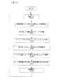
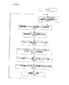
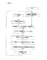
図12は、この実施の形態における演算処理の流れを示すフローチャートである。
まず、ステップS101では、図2のカメラAとBのステレオ画像、すなわち画像Aと画像Bを入力する。
次に、ステップS102では、視差を求めることによって距離画像を作成し、作成した距離画像から先行車の位置と距離を検出する(前記図4〜図6参照)。
【0061】
次に、ステップS103では、まず、距離画像から先行車の存在する横(x軸)方向の範囲を(x1〜xr)を求める(図6、図8参照)。また、距離画像から求めた先行車までの距離Zをもとに前記(数2)式により、先行車の概略の上下端yu、ydを求め、yu、ydを含む大きさの縦長のウィンドウを設ける(前記図6〜図8参照)。
ウィンドウの横方向の大きさは、y座標毎のヒストグラムが求められるよう10画素程度以上とすれば十分である。または、先行車の画像上の大きさは距離に応じて可変であるため、その距離に応じて、横幅が10画素以上のウィンドウが5個所以上に定義できるように適度な大きさで可変としてもよい。
また、(数2)式をもとにウィンドウの上下端の定義位置yu+α、yd−αを求める際に用いる先行車の高さhは1〜2m程度の平均的な値で十分である。また、余裕値αの値は、そのときの先行車の距離に応じて、先行車の高さの5分の1程度のマージンでよい。例えば、(数2)式より、距離から算出される先行車の画像上の高さが50画素程度の場合、αは10画素程度でよい。
【0062】
次に、ステップS104では、ステップS103で定義した縦長のウィンドウ内の水平エッジのヒストグラムを求める(図8参照)。この際、水平エッジのヒストグラムは、図8(B)に示したように、ソーベルフィルタなどでウィンドウ内の画像を水平微分し、その水平微分画像の各y座標毎のヒストグラムをとればよい。
【0063】
次に、ステップS105では、これらのヒストグラムから先行車上の水平エッジを検出する。すなわち、図8で定義したウィンドウの全てにおいて求めた水平エッジのヒストグラムから、半数以上のウィンドウにおいて同じ位置に検出されているエッジを見つける。先行車は路面に対して平行なエッジを持つため、先行車上に切ったウィンドウにおいて同じ位置に検出されるエッジは先行車のエッジであると一応みなすことができる。
【0064】
なお、先行車上に定義するウィンドウを一つにすると、そのウィンドウの両端部分に白線が撮像される場合には、白線のエッジ強度が先行車のエッジ強度より強くなることが多いため、先行車ではなく白線の位置が検出されることがある。そのため、このような誤検出を防ぐためにウィンドウを複数設け、複数のウィンドウにおいて検出されたエッジを先行車上のエッジと判断するようにしている。
【0065】
次に、ステップS106では、ステップS105で求めた先行車上のエッジの移動ベクトルを検出する(図9参照)。エッジの移動ベクトルの算出は、前述の方法で検出したエッジの位置において、例えば、検出対象上に切った小さなウィンドウの移動方向を求める方法などによる一般的なオプティカルフロー検出手法を施せばよい。このような処理により検出した全てのエッジのオプティカルフローより検出した各エッジ毎の移動ベクトルを求める。
【0066】
また、ステップS106においては、上記のエッジの移動ベクトルを用いて、そのエッジが先行車上のものであるか否かを再確認する。この確認は、車間距離変化とエッジが存在する位置により、次のような基準で判断できる(図9参照)。まず、車間距離が変化したときは、画像の中心に近いエッジの方が動きが小さく、画像の端に行くにつれ動きが大きくなる。そのため、例えば、y=0(原点:画像中心)の位置に近いにもかかわらず、そのエッジより原点から遠い位置にあるエッジベクトルの平均の動きよりも大きな動きを示すベクトルがあれば、それは先行車以外のエッジである可能性が高い。また、図9に示したように、車両上のエッジは、y<0の範囲とy>0の範囲とで移動方向が上下逆になるので、それと反対の動きをするエッジは先行車以外のエッジと判断出来る。また、車間距離変化が0のときに大きな動きを示したエッジも先行車以外のエッジと判断できる。このような判断基準をもとに、先行車以外の可能性の高いエッジを除去し、残ったエッジ(上記の基準に適合したエッジ)を先行車上のエッジと判断する。これにより、歩道橋や光の反射等の誤ったエッジを除去し、確実に先行車上のエッジを選択することが出来る。
【0067】
次に、ステップS107では、エッジ間距離の変化率を算出し、それに基づいて車間距離の変化率(エッジ間距離の変化率の逆数に等しい:数4式参照)を算出する。
まず、図8、図9の方法で検出した先行車上のエッジの中から2本ずつの組を作り、全ての組におけるエッジ間距離を求める(図10参照)。前述したとおり、同じ物体上のエッジの組であれば、どの組でもエッジ間距離の時間的な変化率(y1t/y1t−1、y2t/y2t−1、…、ynt/yn−1)は同じ値となるはずである。
【0068】
ここで、エッジ間距離の変化率の求め方を具体的に説明する。図9の判断基準により選択されたエッジはオプティカルフローにより時間的な移動ベクトルが求められているエッジである。そのため、そのベクトルの始点が前回のエッジ位置、終点が今回のエッジ位置となる。つまり、前回のエッジ間距離ynt−1(n:1、2、…、)は、エッジ間距離を求める対象の二つのエッジの移動ベクトルの始点と始点との距離となり、今回のエッジ間距離ynt(n:1、2、…、)は、二つのエッジの移動ベクトルの終点と終点との距離として求められる。この方法で全ての組におけるエッジ間距離の変化率ynt/ynt−1(n:1、2、…、)を求めれば、その中から最も多く同じ値が求められた各組のエッジを先行車上のエッジと判断することができる。
【0069】
また、そのエッジ間距離の変化率の逆数はその時点での車間距離の変化率となる。この方法では、選択した2本のエッジ間距離だけでなく、同じ変化率を示す多くのエッジ間距離の変化をみているため、1、2本のエッジ検出ミスがある場合でも車間距離の変化率を正しく求めることができる。したがって、車間距離変化率計測の確実性を向上させることが出来る
次に、ステップS108では、上記のエッジ間距離の変化率をもとに、ステレオ画像処理で計測した車間距離の再確認を行なう。
(数4)式で説明したように、エッジ間距離の変化率の逆数は車間距離の変化率となる。つまり、1回前のエッジ間距離に対する今回のエッジ間距離の変化率を求めた場合、1回前にステレオ画像処理で視差から求めた車間距離Zt−1に対して、エッジ間距離の変化率の逆数をかけることで今回の車間距離Ztを算出することができる。ステレオ画像処理の視差による車間距離算出も毎回行われているため、この変化率を用いることでステレオ画像処理で求めた車間距離の確認にもなる。さらに、図11でも説明したように、エッジ間距離の変化率から求めた車間距離の変化率は、ステレオ画像処理で連続的に求めた車間距離から求められる車間距離の変化率よりも高精度であるため、計測車間距離自体の高精度化にも貢献できる。
【0070】
また、(数5)式、(数6)式の説明の際、追従中の先行車の高さhを算出することで、エッジ間距離からも車間距離算出が可能になることを説明したが、実用的には、上記hを求める際に用いたエッジが前記図9および図10の判断によって先行車以外のエッジであると判断された場合には、他の2本のエッジ間距離を用いて新たな値にhを算出し直すことで対応する。これにより、エッジ間距離を用いた車間距離算出の誤計測を防ぐことができ、さらに、先行車の入れ替わりなどによる車高hの変化にも対応可能となる。すなわち、先行車が入れ替わった場合には、その際に車高hが不連続に変化し、その後はほぼ一定になるので、このような場合には先行車が入れ替わったものと判断してその後の処理を実行すれば良い。
【0071】
上記のように、第1の実施の形態においては、車両に設置した光軸が平行なステレオカメラで求めた画像に基づいて、視差から求めた距離画像から画像上の横方向における先行車の位置と先行車までの実際の車間距離とを概算し、距離画像から求めた画像上の位置において、そのときの車間距離をもとに先行車の上下端を含む大きさの縦長(または横長)のウィンドウを複数切り、それらのウィンドウの各y座標毎において水平エッジのヒストグラム(または各x座標ごとにおいて垂直エッジのヒストグラム)をとり、定義したウィンドウの中の多くのウィンドウにおいて同じ位置で検出されたエッジを一応先行車上のエッジと判断し、さらに、そのエッジの移動ベクトルを求め、ステレオ画像処理で求めた車間距離変化と適合する方向および大きさの移動ベクトルを示すエッジだけを先行車のエッジとして選択するように構成したことにより、歩道橋、白線、路面表示などのような、先行車以外の強度の強いエッジを誤検出することなく、確実に先行車の上のエッジを選択することが出来る。
【0072】
また、同じ物体上のエッジ間距離の時間的変化率は、どのエッジ間距離においても同じであることから、上記の検出したエッジを2本ずつ組にし、全ての組においてエッジ間距離の時間的変化率を求め、変化率の異なる組のエッジを先行車以外のエッジとして除去するように構成したことにより、先行車上にかかる光のノイズなどの除去が可能になり、より確実に先行車を構成するエッジだけを選択することが可能となる。
【0073】
さらに、この方法によって先行車以外のエッジを除外することにより、除外したエッジの位置の視差を車間距離算出の際に除外することができるので、路面表示など先行車周囲にエッジが多く存在する環境や光の位置などによってノイズの多い環境下でも確実性の高い車間距離計測が可能となる。
【0074】
また、上記のエッジ間距離の変化率より、最も多くの組において同じ値で算出された変化率をもとに、その時点での車間距離の変化率を求めるように構成したことにより、1枚の画像だけを用いた処理において、光のノイズや影など、多少のエッジ検出ミスがあるときだけでなく、先行車上のエッジを検出しにくい環境下でも、車間距離の変化率を確実に正しく求めることが可能となる。
【0075】
また、ステレオ画像処理で過去に求めた車間距離に対して、車間距離の変化率を乗算することで、処理時点での新たな車間距離を算出するように構成したことにより、ステレオ画像処理で求めた車間距離との照合・確認が可能となる。さらにエッジ間距離の変化率から求めた車間距離の変化率は、ステレオ画像処理で連続的に求めた車間距離より求められる車間距離の変化率よりも高精度であるため、計測車間距離自体の高精度化にも貢献できる。
【0076】
(第2の実施の形態)
前記第1の実施の形態においては、二つのカメラによるステレオ画像処理によって車間距離計測を行なうものについて説明したが、第2の実施の形態においては、二つのカメラの代わりに、いわゆるレーザレンジファインダを用いて車間距離計測を行なう装置について説明する。
【0077】
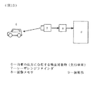
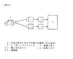
図13は本発明の第2の実施の形態の構成を示すブロック図である。
図13において、7はレーザレンジファインダであり、自車の前部に前方を向いて設置されている。なお、車両の後部に後方を向けて設置し、車両後方の障害物を検出するように構成することもできる。このレーザレンジファインダ7は、レーザレーダの照射を縦横に走査することで、前方の物体までの距離とその照射対象の反射強度(輝度)を2次元的に計測する装置である。また、8はレーザレンジファインダ7から入力した画像信号を記憶する画像メモリであり、後記の輝度画像と距離画像を記憶する。9は演算部であり、例えばCPU、RAM、ROM等からなるマイクロコンピュータで構成される。その他、図1と同符号は同じものを示す。
【0078】
以下、まず第2の実施の形態に用いる種々の演算手段と方法について説明し、それからフローチャートに基づいて全体の演算の流れを説明する。
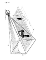
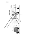
図14は、車両が走行する方向を中心として左右上下に道路前方を走査するレーザレンジファインダ7と計測対象物(先行車6)との位置関係を示す図である。レーザレンジファインダ7は、走査の中心軸が路面に平行で、かつ、直進する自車両の走行方向を向くように搭載されている。
【0079】
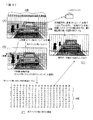
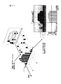
また、図15は図14のレーザレンジファインダ7で計測した距離画像と輝度画像の一例を示した図であり、(A)は輝度画像をイメージで示した図、(B)は距離画像をイメージで示した図、(C)は距離画像の内容(数値:例えばディジタル値)を示した図である。距離画像とはレーザレンジファインダで計測される各角度毎の測定距離の2次元配列を、輝度画像とは反射光の強度の2次元配列を意味するので、実際の輝度画像および距離画像は図15(C)に示したような数値表(実際にはディジタル値)になるが、輝度画像の内容(数値表)は図示を省略している。また、図15(C)において、「−1」は距離が測定可能距離の範囲外で測定不能な個所(例えば空)を示す。また、「18」、「28」、「40」等の数値は対象物までの距離(m)を示している。
【0080】
以下、画像の横軸をx軸、縦軸をy軸、原点を画像の中心として説明する。
ここで得られる輝度画像および距離画像上の点の座標と、その座標上の点を計測した対象となる実空間上の点の位置関係は、図14に示すように、走査範囲の角度と、値を計測するサンプリング間隔毎に動く照射の角度の大きさ(角度分解能)で決まる。例えば、縦、横の角度分解能がそれぞれ、θ、φのとき、画像上の座標(x=2、y=3)の位置に対応する実空間上の位置は、レーザレンジファインダの中心軸(画像面に垂直な軸)から、横に2θ、縦に3φの方向の最も近い位置にある物体面上の点となる。また、距離画像と輝度画像の互いに同じ座標位置の計測値は、実空間上で同じ位置の計測値である。
【0081】
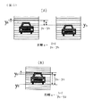
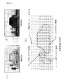
図16(A)は、図15の距離画像において、先行車と同じ距離を示す部分だけを太線で表した図である。道路前方に先行車がある場合には、図示のように、先行車と同じ距離を示す部分は、先行車上とその先行車の真下の路面の部分となる。つまり、物体が存在する位置では同じ距離を示す値が隣接する。また、図16(B)は、前方に先行車がないときの計測結果である。図示のように、路上に先行車などの物体がないときは、画像の下半分の領域には路面が撮像(上半分は空)されるため、この下半分の領域で計測された距離は画面の下から上に向けて近距離から遠距離になる。つまり、物体が存在する場合には、同じx座標上に同じ距離を示す画素が並ぶが、物体が無い場合にはx座標上には同じ距離の値は存在しない。このことから、図17に示す方法で物体の検知・計測が可能となる。
【0082】
図17は、z軸方向に距離をとり、x軸を画像のx軸方向として投票した値をy軸方向に示したグラフである。図15(C)のごとき距離画像の値をもとに、図17の対応する位置に投票する。投票とは、例えば、x=2上にある画素で距離が3mの点のとき、グラフのx=2、z=3のところにy=1を加算する操作を意味する。詳細は、前記第1の実施の形態において図4〜図6で説明した方法と同様である。
【0083】
このような操作を距離画像全体の値について行なう。前方zの位置に物体が存在する場合、その物体が撮像されるx座標の距離zの位置に複数回投票が繰り返されるため、表中のその位置の値が高くなる。一方、物体が存在しないx座標上では、図16(B)に示したように、同じx座標上で同じ距離は計測されないため、表中で値が高くなる位置は存在しない。このことから、投票結果をもとに、表中の値が大きな位置の存在から物体の有無を求めることが出来る。また、その物体の存在する位置は、x軸方向の範囲は投票値が所定値以上の範囲xl〜xr(xlは存在範囲の左端、xrは右端)のx軸方向の位置により、物体までの距離は表の距離zの値により、それぞれ求めることができる。
【0084】
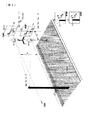
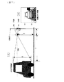
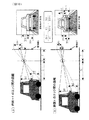
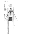
次に、輝度画像上から先行車の撮像範囲を求める方法を説明する。撮像範囲のx軸方向の範囲は、前述の方法でxl〜xrと求められる。また、画像のy軸方向の範囲は次のような原理から求める。図18〜図20は、レーザレンジファインダで撮像した距離画像と輝度画像において撮像範囲と先行車までの距離の関係を表す図であり、図18は平面図、図19は側面図、図20は先行車の存在範囲を示す画像である。以下、図18〜図20を用いて、y軸方向の範囲の求め方を説明する。
【0085】
画像上の先行車の上端の位置をy=yu、下端をy=ydとする。縦方向の角度分解能がφ、先行車までの距離がz、路面からレーザレンジファインダの中心軸までの高さをH、先行車の高さをhとすると、図19より、そのレーザレンジファインダで計測した輝度画像上における先行車の上下端(yu、yd)は、
tan(yu×φ)=(h−H)/z、 tan(yd×φ)=−H/z
の関係となる。ただし、ここでは、下端はほぼ路面と同じ高さとみなす。また、θ、φは微小角であるので、tanθ≒θ、tanφ≒φである。このことから、(yu、yd)は下記(数7)式で求められる。
【0086】
yu=(h−H)/(φ×z)、 yd=−H/(φ×z) …(数7)
上記の方法により、左上端が(xl、yu)、右下端を(xr、yd)として先行車が撮像される画像上の範囲を図20に示すように求めることができる。
【0087】
次に、上記の方法で求めた輝度画像上の先行車の撮像範囲に縦長のウィンドウを切り、先行車上の水平エッジを検出する。これらの縦長のウィンドウを設定する横方向の位置は距離画像から検出した先行車が撮像される範囲xl〜xrとすればよい。また、縦方向の位置は、(数7)式に基づいてyuとydが含まれる程度の大きさ(上がyu+α、下がyd−α)にすればよい。これを用いて水平エッジを検出する方法の内容は、前記第1の実施の形態における図8およびその説明と同様なので省略する。なお、縦エッジを検出する場合は、同様の処理を横長のウィンドウを切ってy座標をx座標に置き換えて行えばよい。また、後述する移動ベクトルやエッジ間距離の計算においても同様である。
【0088】
次に、上記の方法で検出したエッジの移動ベクトルを求め、そのエッジの中から、先行車の動きに基づいた動きをするエッジだけを選択するが、この内容は、前記第1の実施の形態における図9およびその説明と同様なので省略する。
【0089】
次に、エッジ間距離の変化率および車間距離の変化率を求める方法と、その結果を用いて先行車上のエッジを再確認する方法について説明する。なお、この方法は前記第1の実施の形態における図10およびその説明と類似しているが、画像入力手段がステレオカメラとレーザレンジファインダとで異なっているため、数式等が一部異なっているので、改めて説明する。
【0090】
図21は、輝度画像上の先行車の上下端の撮像された位置と先行車までの距離の関係を表す図であり、(A)は時点t−1における位置、(B)は時点tにおける位置を示す。
図21に示すように、追従中の車両上から、バンパーなど路面に平行な線を異なる位置から2本ずつ2組選択し、その2本の平行線間の距離をh1、h2とする。時点t−1における車間距離がzt−1のときのh1、h2の画像上の長さをそれぞれy1t−1、y2t−1とすると、y1t−1、y2t−1は、それぞれ下記(数8)式に示すようになる。
【0091】
y1t−1=(h1/φ)/zt−1、 y2t−1=(h2/φ)/zt−1…(数8)また、時点tにおける車間距離をztとすると、同様に、そのときの画像上のh1、h2の長さは、y1t=(h1/φ)/zt、y2t(h2/φ)/ztとなる。これらから、車間がzt−1からztに変化したときの画像上のエッジ間の長さの変化率は、h1、h2ともに、下記(数9)式に示すようになる。
【0092】
y1t/y1t−1=y2t/y2t−1=zt−1/zt …(数9)
つまり、エッジ間距離に関わらず、エッジ間距離の変化率は、それらのエッジが同じ物体上のものであれば、どのエッジが選択された場合でも同じ値になり、その値は、車間距離の変化率(zt/zt−1)の逆数(zt−1/zt)となる。
このことから、図8の方法によって検出した画像上の車両のエッジから2本ずつの組を作り、それらのエッジ間距離の時間的な変化率(y1t/y1t−1、y2t/y2t−1、…、ynt/ynt−1)を求め、それらの組ごとに求めたエッジ間距離の変化率から、その値が同じである最も多い組のエッジを先行車上のエッジであると再確認することができる。
【0093】
さらに、或るエッジを含む組に限り、時間的変化率が常に他の組と異なるものがあれば、そのエッジを先行車以外のエッジとして除外できる。これにより、先行車付近の路面表示や路面のノイズなど先行車以外の反射からくる光のノイズを、先行車以外のエッジとして除去することが可能となる。また、同時に、その最も多くの個所で求められたエッジ間距離の変化率は、その時点での画像上の先行車の大きさの変化率となる。つまり、この変化率の逆数をとることで、車間距離の変化率も求めることができるようになる。このように輝度画像から求めたエッジ間距離の変化率から車間距離の変化率を求めることが出来る。
【0094】
そして車間距離の変化率が求まれば、その値を所定演算回数前に計測した車間距離の値に乗算することにより、前記第1の実施の形態における(数6)式、(数6’)式で説明したのと同様に、車間距離の値を求めることが出来る。
この方法では、レーザレンジファインダの距離画像による距離測定と同時に、レーザレンジファインダで得られた輝度画像からも距離の変化率を求めることが出来るので、両者を比較・照合することにより、より確実な距離計測が可能になる。
【0095】
また、図21等で説明した輝度画像からの距離変化測定方法は、先行車上に検出されるエッジのうちの数本が検出できれば、車間距離の変化率を計測可能となる。したがって、エッジを検出しにくい形状・環境でも距離の変化率の計測は可能である。また、逆にノイズの多い環境であっても、その中から、先行車の車間変化に合った動き、変化率を示すものだけを選択するので、ノイズに影響されることなく車間距離の変化率が計測できる。このように、環境変化に影響されない確実性の高い距離測定が可能となる。
【0096】
次に、前記図9、図21で説明した輝度画像からの先行車上のエッジ選択において、先行車以外のエッジであると選択されたエッジがある場合には、そのときの距離画像上におけるそのエッジの存在位置の距離は誤った値である可能性が高い。このことから、図17の表への投票の際に、先行車以外と判断されたエッジの存在位置の距離を用いないようにすることも有効である。このことにより、表への投票の際に誤計測値が反映されないため、車間距離計測の確実性を向上させることが出来る。
【0097】
次に、レーザレンジファインダは、装置から照射した光が反射して戻ってくるまでの時間をもとに距離を計測する。そのため反射光の強度が弱い位置の計測値は信頼度が低い。また、光を吸収してしまう物体に照射した場合は反射光が返ってこない場合もあり、そのような位置の計測距離の値は誤計測値である。そのため、レーザレンジファインダから計測した輝度画像上において、輝度値が低い位置で計測された距離画像上の値を、図17の表への投票の際に用いない構成とすることも有効である。これにより、信頼性の高い値だけを用いた距離計測が行われるようになり、同時に、誤計測値が車間距離計測に反映されないため、車間距離計測の確実性を向上させることが出来る。
【0098】
次に、これまで説明した方法を用いて、追従中の先行車上のエッジを検出し、車間距離の変化率を求めることで車間距離の確認および高精度化を行う実施の形態について説明する。ここでは、前記図14のようにレーザレンジファインダを車両の前方を向けて搭載した場合について説明する。
【0099】
図22は、この実施の形態における演算処理の流れを示すフローチャートである。
まず、ステップS111では、レーザレンジファインダの輝度画像と距離画像を入力する(図15参照)。
次に、ステップS112では、まず、距離画像から表へ投票することにより、先行車の存在する横(x軸)方向の範囲(xl〜xr、)と先行車までの距離zを求める(図16、図17参照)。ただし、この距離画像からの表への投票は、誤計測値が反映されないように、表へ投票する値を、レーサレンジファインダで計測した輝度がしきい値以上の位置の値だけとした上で図17に示した方法で行なう。また、後の処理である先行車のエッジ判断処理(ステップS115)において、先行車のエッジ検出用のウィンドウ内にあるが、先行車上のエッジではないと判断された位置の値も除外して投票してもよい。
【0100】
次に、ステップS113では、輝度画像から先行車の上下方向の範囲(yu〜yd)を検出する(図18〜図20参照)。
次に、ステップS114では、ステップS112とステップS113で検出した先行車の撮像範囲に縦長または横長のウィンドウを定義する。また、ステップS115では、上記ウィンドウ内のヒストグラムを求めることによって先行車上のエッジを検出する。さらにステップS116では、エッジの移動ベクトルを求め、そのエッジの中から、先行車の動きに基づいた動きをするエッジだけを選択する。これらのステップS114〜ステップS116の内容は、前記第1の実施の形態における図12のステップS103〜ステップS106の内容と同様である。
【0101】
次に、ステップS117では、エッジ間距離の変化率を求め、その結果から車間距離の変化率を求める(図8、図21参照)。この内容は前記第1の形態における図12のステップS107とほぼ同様である。
次に、ステップS118では、レーザレンジファインダの距離画像から求めた車間距離と、ステップS117で求めた車間距離の変化率から算出した車間距離とを照合し、距離計測の正確性を再確認する。すなわち、所定演算回数前の計測した車間距離Zt−1に対して、今回演算した車間距離の変化率を乗算すれば今回の車間距離Ztを算出することができる。このように、レーザレンジファインダによる距離画像から求めた車間距離と、輝度画像から求めた距離の変化率に基づく車間距離とを比較・照合することにより、より確実な距離計測が可能になる。
【0102】
以上説明してきたように、第2の実施の形態においては、車両に設置したレーザレンジファインダの距離画像と輝度画像を求め、得られた距離画像から、輝度画像上の横方向における先行車の撮像位置と自車から先行車までの実際の距離を計測し、輝度画像上において、そのときの車間距離に基づいて先行車の上下左右端を含む大きさの縦長(または横長)のウィンドウを複数設け、それらのウィンドウの各y座標(またはx座標)毎において水平(または垂直)のエッジのヒストグラムをとり、設定したウィンドウの中の多くのウィンドウにおいて同じ位置で検出されたエッジを先行車上のエッジであると一応判断し、さらに、そのエッジの移動ベクトルを求め、ステレオ画像処理で求めた距離変化と適合する方向・大きさの移動ベクトルを示すエッジだけを先行車のエッジとして選択する。さらに、選択したエッジ間距離の変化率をもとに、変化率が同じ組のエッジだけを先行車上のエッジと判断し、そのエッジ間距離の変化率の逆数より車間の変化率を求めるように構成している。そのため、レーザレンジファインダの計測距離の分解能より細かい精度での距離計測が可能となり、同時に二つの手法による計測結果の照合により確実な距離測定が可能となる。
【0103】
さらに、このエッジ検出方法は、先行車上のエッジをヒストグラムと移動ベクトルとエッジ間距離の変化率とから判断しているため確実であり、その方法により、先行車上と考えられるエッジを選択した後、それらのエッジ間距離の変化率から先行車の車間距離の変化率を求めているため、エッジ間距離から計測した車間距離の変化率は、エッジの検出しにくい環境においてもその中の数本が検出できれば車間距離の変化率計測が可能であり、かつ、ノイズの多い環境下でも、ノイズが除去されるため、周囲環境に対して影響されにくい確実な計測装置を実現出来る。
【0104】
また、先行車以外のエッジと判断された位置におけるレーザレンジファインダで計測した距離画像上の値を、車間距離計測の際の判断に反映させない構成としたため、ノイズなどによる誤計測値を除去でき、より正確な測距が可能となる。
【0105】
また、距離画像からの車間距離計測において、レーザレンジファインダの輝度画像上の反射強度が低い場合には、その位置で計測された距離を反映させない構成としたため、誤計測値を除去でき、さらに、信頼度の高い計測値だけを用いた、より正確な測距が可能となる。
【0106】
また、カメラによる画像は夜間のような暗い状況下では使用困難であるが、レーザレンジファインダは夜間等でも使用可能である。
【0107】
(第3の実施の形態)
前記第1の実施の形態においては、2つのカメラを用いたステレオ画像処理によって車間距離計測を行なう装置、前記第2の実施の形態においては、2つのカメラの代わりに、いわゆるレーザレンジファインダを用いて車間距離計測を行なう装置について説明したが、第3の実施の形態においては、レーザレンジファインダと1つのカメラを用いる装置について説明する。
【0108】
第2の実施の形態で測距用に用いているレーザレンジファインダにおいては、一般に、前方の物体までの距離を計測する光の走査機構として、光の照射角度をミラーの回転などによって変更する機構を用いているため、装置の信頼性を高くするためには、走査を遅くすることが要求される。つまり、この要求を満たすためには、1回の2次元情報を得るためのサンプリング間隔を広げる必要がある。また、装置の信頼性を高めるためには、発光パルスの照射間隔を広げることも必要となる。つまり、故障率が低く信頼性の高いレーザレンジファインダとするためは、1回の2次元情報を得るのにかかる時間を長くする必要があり、さらに、2次元的な縦横の分解能および測定距離の分解能も粗くする必要がある。そのため測定結果の精度が低下し、かつ、測定の時間間隔が長くなるという問題が生じる。その問題に対処するため、第3の実施の形態では、レーザレンジファインダとカメラとを組み合わせて用いるように構成している。
【0109】
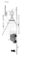
図23は本発明の第3の実施の形態の構成を示すブロック図である。
図23において、10は電子式のカメラであり、このカメラ10の光軸がレーザレンジファインダ7の走査の中心の軸と平行になる位置および姿勢で車両に搭載されている。11はカメラ10から入力した画像信号を記憶する画像メモリである。12は演算部であり、例えばCPU、RAM、ROM等からなるマイクロコンピュータで構成される。その他、図13と同符号は同じものを示す。
【0110】
以下、まず第3の実施の形態に用いる種々の演算手段と方法について説明し、それからフローチャートに基づいて全体の演算の流れを説明する。
この実施の形態においては、レーザレンジファインダ7に加えて、それと同じ平面の輝度画像が得られるカメラ10を搭載し、第2の実施の形態においてレーザレンジファインダ7の輝度画像に施した処理を、カメラ10で撮像した画像に対して行い、エッジの検出およびエッジ間距離の変化率から車間距離の変化率を求める。これには、まず、レーザレンジファインダ7の距離画像から求めた先行車の画像上での位置を、カメラ10で撮像した画像上での位置に変換し、両者の画像上の位置を合せる必要がある。
【0111】
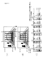
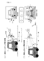
図24は、レーザレンジファインダ7の上で間隔Aだけ上方に離れた位置に、レーザレンジファインダ7の走査の中心の軸とカメラの光軸が平行になる位置および姿勢でカメラ10を搭載した場合における、二つの装置およびその撮像対象となる車両の位置関係を示した図である。また、図25(A)、(B)は、図24の環境下において計測した輝度画像の様子を表した図であり、(A)はレーザレンジファインダ7の輝度画像、(B)はカメラ10の輝度画像を、それぞれ画像のイメージで示している。なお、実際の輝度画像は、輝度に対応したディジタル値の2次元配列になる。
【0112】
第2の実施の形態でも説明したように、レーザレンジファインダで計測した輝度画像上の位置と実空間における対象物の位置との関係は前記(数7)式で求められる。また、カメラの場合には、図26に示すように、画像1画素に対応する角度を求めておくことにより、(数7)式と同様の原理によって画像上の座標とその位置に撮像される実空間上の点との位置関係を求めることができる。なお、図26においては、縦方向の1画素分の角度βのみを表示しているが、横方向についても同様に角度αを求める。
【0113】
例えば、レーザレンジファインダの一つの画素に対応する縦、横の角度をφ、θ、カメラ画像の一つの画素に対応する縦、横の角度をβ、αとすると、図24の配置において、距離zの位置にある車両上の或る1点pが、レーザレンジファインダで計測した距離画像上では(xp1、yp1)に撮像されたとき、その点pが撮像される画像上の座標(xpi、ypi)は、
xpi=xp1・(θ/α)、 ypi=yp1・(φ/β)−A/(β・z)
となる。ただし、通常、A<<zであるので、Aは無視できる大きさとすると、両画像間の位置対応は、下記(数10)式で算出される。
【0114】
xpi=xp1・(θ/α)、 ypi=yp1・(φ/β) …(数10)
カメラで撮像した方の画像処理に関しては、(数10)式のスケーリングを施した上で、図17〜図21で説明したエッジ検出およびエッジ間距離の変化率測定処理において、レーザレンジファインダの輝度画像の代わりにカメラの輝度画像を用いて同様の処理を行なう。これにより、第2の実施の形態と同様の効果が得られる。さらに、レーザレンジファインダの輝度画像よりもカメラの画像の方がエッジが鮮明であり、縦横の分解能が細かいことから、この効果をより向上させることができる。加えて、カメラの画像入力周期はレーザレンジファインダの画像更新周期より短いことから、距離の変化率を短い時間間隔で求めることも可能となる。その他の処理は前記第1および第2の実施の形態と基本的には同じである。
【0115】
なお、レーザレンジファインダの距離画像と輝度画像に関しては前記第2の実施の形態で説明した各種の処理を施すことが出来る。例えば、図17の方法により、先行車までの距離は、レーザレンジファインダの走査完了毎に距離画像から計測することで、1回の走査にかかる時間を周期として連続的に計測することができる。また、レーザレンジファインダの輝度画像から求めたエッジ間距離の変化率に基づいた車間距離の変化率算出も同じ周期で連続的に計測できる。
【0116】
また、車間距離計測において、同じ車両に追従中の場合は、1度車間距離を求めておけば、その車間距離に対してエッジ間距離の変化率を乗算することで、その時点での距離を算出することが可能となる。すなわち、レーザレンジファインダで計測した時点tでの車間距離がzt、時点t+1に計測した車間距離の変化率(エッジ間距離の変化率の逆数)がγであれば、時点t+1での車間距離zt+1は、下記(数11)式で計算できる。
zt+1=γ×zt …(数11)
レーザレンジファインダの距離分解能は粗く、縦横の分解能は細かい場合においては、この計算による距離の再計算は、距離の高精度化にもつながる。
【0117】
また、上記の方法による距離の更新は、第3の実施の形態のようにカメラとレーザレンジファンダの両方を搭載したシステムにおいては、距離計測の時間間隔を短くすることにもつながる。例えば、レーザレンジファインダの計測間隔時間が1秒、カメラの撮像間隔が16.7ms(1フィールド)である場合、レーザレンジファインダからの画像入力は1秒毎にしかできないが、カメラ画像から求めたエッジ間距離の変化率に基づく車間距離の変化率は16.7ms毎に計測される。したがって、レーザレンジファインダのみの場合には車間距離計測は1秒毎にしか出来ないが、時点tでレーザレンジファインダで計測した距離ztに対して、前記(数11)式を適用して演算すれば、車間距離の演算を16.7ms毎に処理することが出来る。図27は上記の計測タイミングを示した図である。
【0118】
さらに、このエッジ間距離の時間的な変化率を利用した車間距離測定は、距離の確認および距離の高精度化にもつながる。以下、カメラ画像を用いたエッジ間距離からの車間距離変化率算出により、距離算出の精度が向上される原理を説明する。
図19に示した先行車の高さhは通常は未知の値である。しかし、レーザレンジファインダで距離が求められているときは、先行車までの車間距離zと輝度画像上の先行車の高さ(yu−yd)を下記(数12)式に代入することで追従中の車両の高さhを求めることができる。
【0119】
h=β×(yut−ydt)×zt …(数12)
ただし、β:1画素分の角度
同じ車両に追従中は、hは一定値である。ここでは、画像上の先行車の高さ(yu−yd)は、前記の先行車上のエッジ検出処理により求めることができるため、(数12)式により1度求めたhをもとに、次の入力画像で求めた先行車の高さ(yut+1−ydt+1)を、下記(数13)式に代入することで、先行車の高さからも新たな車間距離を求めることができる。
【0120】
z=h/β(yut+1−ydt+1) …(数13)
ただし、h:(数12)式で算出した値
(数12)式のhを(数13)式に代入すると下記(数13’)式のようになる。
Zt+1=Zt×(yut−ydt)/(yut+1−ydt+1)
或いは …(数13’)
Zt=Zt−1×(yut−1−ydt−1)/(yut−ydt)
ただし、Zt+1:時点t+1における車間距離
Zt:時点tにおける車間距離
Zt−1:時点t−1における車間距離
(数13’)式からもわかるように、この方法で求める車間距離は、画像上で検出したエッジ間距離の変化率の逆数(yut−ydt)/(yut+1−ydt+1)をレーザレンジファインダの距離画像から時点tで求めた距離ztにかけることと同じである。つまり、前記(数11)式と同様の計算により、車間距離が求められることがわかる。
【0121】
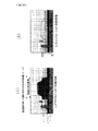
ここで、前記第2の実施の形態においてレーザレンジファインダの輝度画像と距離画像の処理によって(数11)式で求める方法と、カメラの輝度画像とレーザレンジファインダの距離画像とを用いて(数13)式で求める方法とにおける距離の精度の違いを考える。例えば、レーザレンジファインダの距離分解能を1mとし、カメラの画素の分解能を通常の車載システムを参考に、画角30度で縦に480画素の分解能の画像を撮像すると仮定する。このときの画像の1画素分の分解能βは、0.001rad(=2π×(30/480)/180)である。このシステムにおいて、高さ1mの車両までの距離を算出すると、レーザレンジファインダでの計測距離分解能は常に1mであるのに対し、画像のエッジ間距離で求める分解能は、距離に応じて下記(数14)式で求められる値となる。
【0122】

【0123】
次に、これまで説明した方法を用いて、追従中の先行車上のエッジを検出し、車間距離の変化率を求めることで車間距離の確認および高精度化を行う実施の形態について説明する。ここでは、前記図24のようにレーザレンジファインダとカメラを車両の前方を向けて搭載した場合について説明する。ただし、計算を簡略化するため、カメラとレーザレンジファインダの搭載位置の差(図24の間隔A)は、無視できるものとして説明する。しかし、実際の場合において、間隔Aが大きな値である場合でも、間隔Aの差によって表れる画像上の位置の差を幾何学的に考慮することで同様の処理・効果が得られる。
【0124】
図29は、この実施の形態における演算処理の流れを示すフローチャートである。
まず、ステップS121では、レーザレンジファインダの輝度画像と距離画像を入力する。また、ステップS122ではカメラの画像(輝度画像)を入力する(図24、図25参照)。
【0125】
次に、ステップS123では、カメラの画像に対してレーザレンジファインダの画像との位置合わせを行なう(図24〜図26参照)。
【0126】
なお、この実施の形態では、基本的にはレーザレンジファインダの輝度画像の代わりにカメラの輝度画像を用いるので、前記図22におけるステップS113のレーザレンジファインダの輝度画像から先行車範囲を検出する処理は無くてもよい。ただし、図22のようにレーザレンジファインダの輝度画像と距離画像から演算する方法も同時に行ない、演算結果の車間距離或いはその変化率を、本フローチャートの演算結果と照合するように構成することもできる。また、第2の実施の形態で説明したのと同様に、レーザレンジファインダの輝度画像も求めておき、距離画像からの車間距離計測において、輝度画像上の反射強度が低い場合には、その位置で計測された距離を反映させない構成とすることにより、誤計測値を除去でき、さらに、信頼度の高い計測値だけを用いた、より正確な測距が可能となる。
【0127】
次に、ステップS124では、レーザレンジファインダの距離画像からの表への投票により、先行車の存在する横(x軸)方向の範囲(xl〜xr、)と先行車までの距離zを求める(図17参照)。ただし、この距離画像からの表への投票は、誤計測値が反映されないように、表へ投票する値を、レーザレンジファインダで計測した輝度がしきい値以上の位置の値だけとした上で図17で説明した方法で行なう。また、この後の処理である先行車のエッジ判断処理(ステップS127)において、先行車のエッジ検出用のウィンドウ内にあるが、先行車上のエッジではないと判断された位置の値も除外して投票してもよい。
【0128】
次に、ステップS125では、先行車の上下端検出用のウィンドウを設定する。ここでは、水平エッジを検出するための縦長のウィンドウをカメラの画像上に設定する。すなわち、図17の処理によってレーザレンジファインダの距離画像から求めた横方向の範囲(xl〜xr)に対して前記(数10)式を適用することにより、カメラ画像上における先行車の撮像範囲を求める。ここでは、後の説明において表記を簡略化するため、以降、(数10)式によって大きさを変換した後のカメラ画像上での先行車の撮像範囲も(xl〜xr)と記述する。
【0129】
次に、ウィンドウを定義する縦方向の位置を求める。これは、距離画像から求めた距離zより、(数10)式において、1画素に対応する角度をカメラ画像の角度βとして、上下端(yu、yd)を求める。これらの方法により、求めた横方向xl〜xrの間にyu、ydを含む大きさの縦長のウィンドウを設定する(図8参照)。定義する縦長のウィンドウの横方向の大きさは、y座標毎の水平エッジのヒストグラムが求められるよう10画素程度以上とすれば十分である。または、先行車の画像上の大きさは距離に応じて可変であるため、その距離に応じて、横幅が10画素以上のウィンドウが5個所以上に定義できるように適度な大きさで可変としてもよい。
【0130】
また、(数10)式をもとにウィンドウの定義位置yu+α、yd−αを求める際に用いる先行車の高さhは1〜2m程度と平均的な値で十分である。αの値は、そのときの先行車の距離に応じて、先行車の高さの5分の1程度の余裕でよい。例えば、(数12)式によって距離から算出される先行車の画像上の高さが50画素程度の場合、Cは10画素程度でよい。
【0131】
次に、ステップS126では、上記の設定した縦長のウィンドウの中で求めた水平エッジのヒストグラムをもとに、先行車上のエッジを検出する。これには前記図8で説明した方法を用いる。まず、図8に示すように、ソーベルフィルタなどでウィンドウ内の画像を水平微分し、その水平微分画像の各y座標毎のヒストグラム求める。次に、定義したウィンドウの全てにおいて求めた水平エッジのヒストグラムから、半数以上のウィンドウにおいて同じ位置に検出されているエッジを見つける。先行車は路面に対して平行なエッジを持つため、先行車上に切ったウィンドウにおいて同じ位置に検出されるエッジは先行車のエッジと一応みなすことができる。
【0132】
なお、仮に先行車上に定義するウィンドウを一つとすると、そのウィンドウの両端部分に白線が撮像される場合、白線のエッジ強度が先行車のエッジ強度より強くなることが多いため、先行車ではなく白線の位置が検出されることがある。そのため、このような誤検出を防ぐため、ウィンドウを複数設け複数のウィンドウにおいて検出されたエッジを先行車上のエッジと判断する。
【0133】
次に、ステップS127では、これらのエッジの移動ベクトルを検出する。このエッジの移動ベクトル算出は、前述の方法で検出したエッジの位置において、例えば、検出対象上に切った小さなウィンドウの移動方向を求める方法などによる一般的なオプティカルフロー検出手法を施せばよい。このような処理により検出したすべてのエッジのオプティカルフローより検出した各エッジ毎の移動ベクトルを求める。
【0134】
更に、上記のエッジの移動ベクトルを用いて、そのエッジが先行車上のものであるかを再確認する。この確認は、車間距離変化とエッジが存在する位置により次のような基準で判断できる。すなわち、車間距離が変化したときは、画像の中心に近いエッジの方が動きが小さく、画像の端に行くにつれ動きが大きくなる。そのため、例えば、画像中心(原点:y=0)の位置に近いにもかかわらず、そのエッジより原点から遠い位置にあるエッジベクトルの平均の動きより大きな動きを示すベクトルがあれば先行車以外のエッジである可能性が高い。また、ステレオ画像処理により求めた距離の変化に基づき、図9に示したように、、車間距離が大きくなる場合は、y>0の位置のエッジは下方、y<0の位置のエッジは上方に移動し、車間距離が短くなる場合は、y>0の位置のエッジは上方、y<0の位置のエッジは下方に移動し、車間距離が一定の場合はエッジの位置は不変となる。これらのことから、そのベクトルが図9に示す理論どおりの動きをするものを車両上のエッジとして再確認し、逆の変化するエッジは車両上のものではないと判断することができる。また、車間変化=0のときに大きな動きを示したエッジも先行車以外のエッジと判断できる。このような判断基準をもとに、先行車以外の可能性の高いエッジを除去する。
【0135】
次に、ステップS128では、上記先行車上のエッジ間距離の変化率を求め、それによって、より確実に先行車上のエッジを選択する。それとともに、エッジ間距離の変化から、車間距離計測の高精度化を行なう。まず、上記ステップS128で検出した先行車上のエッジの中から2本ずつの組を作り、それらの各組におけるエッジ間距離を求める(図21参照)。前述したとおり、同じ物体上のエッジの組み合わせであれば、どの組み合せでもエッジ間距離の時間的な変化率(y1t/y1t−1、y2t/y2t−1、…、ynt/ynt−1)は同じ値となるはずである。
【0136】
ここで、エッジ間距離の変化率の求め方を具体的に説明する。図9の判断基準により選択されたエッジは、オプティカルフローにより時間的な移動ベクトルが求められているエッジである。そのため、そのベクトルの始点が前回のエッジ位置、終点が今回のエッジ位置となる。つまり、前回のエッジ間距離ynt−1(n:1、2、…)は、エッジ間距離を求める対象の二つのエッジの移動ベクトルの始点間の距離となり、今回のエッジ間距離ynt(n:1、2、…)は、ベクトルの終点間の距離として求められる。この方法で各組におけるエッジ間距離の変化率ynt/ynt−1(n:1、2、…)を求めれば、エッジ間距離の変化率が同じ値となる組が最も多い組のエッジを先行車上のエッジと判断することができる。また、その変化率の逆数はその時点での車間距離の変化率となる。この方法では、選択した2本のエッジ間距離だけでなく、同じ変化率を示す多くのエッジ間距離の変化を見ているため、1、2本のエッジ検出ミスがある場合でも車間変化率を正しく求めることができる。したがって確実性の高い車間距離変化率測定が可能となる。
【0137】
次に、ステップS129では、エッジ間距離の変化率に基づいて、先行車に追従中における、レーザレンジファインダで計測した車間距離を更新する。(数9)式で説明したように、エッジ間距離の変化率の逆数は車間距離の変化率となる。つまり、レーザレンジファインダで求めた距離ztに対して、時点tで検出したエッジ間距離の変化率の逆数を乗算することで距離を更新することが可能となる(数11式、数13式)。
【0138】
また、レーザレンジファインダは、装置の信頼性向上のため1枚の画像を得るための走査速度を遅くすることが求められるが、この方法では、1回レーザレンジファインダで計測した距離に対して、次にレーザレンジファインダから距離が計測されるまでの間は、画像から計測されるエッジ間距離の変化率による距離の更新を行なうことが出来るので、短い時間間隔での距離測定の更新が可能である(図27参照)。
【0139】
また、レーザレンジファインダで距離が計測された時点では、両者の計測値を比較・照合することで距離の確認を行なうことが出来る。さらにカメラからの画像からだけでなく、レーザレンジファインダで得られる輝度画像でもエッジ間距離からの距離変化を検出(前記第2の実施の形態参照)しておくことで、さらに確実な距離の確認が可能となる。
【0140】
また、前にも説明したように、カメラ画像を用いたエッジ間距離の変化率から求めた車間距離の変化率は、レーザレンジファインダで計測した車間距離の分解能より高精度であるため、計測距離自体の高精度化にも貢献できる。なお、この方法は車両を追従中の車間距離精度向上に適用しているが、実際の場合には、車両の高さhを求めたもととなったエッジが、図9および図21の判断によって先行車以外のエッジと判断されたときは、他の2本のエッジ間距離を用いて新たな値にhを定義し直すことで対応するように構成すれば、エッジ間距離を用いた距離算出の誤計測を防ぐことができ、さらに、先行車の入れ替わりなどによる車高hの変化にも対応可能となる。
【0141】
以上説明してきたように、第3の実施の形態においては、レーザレンジファインダの走査の中心軸と光軸が平行でほぼ同じ画角内を計測する位置および姿勢のカメラを用い、第2の実施の形態においてレーザレンジファインダで計測した輝度画像に対して施した処理を、カメラから撮像した画像に対して施すことにより、レーザレンジファインダとは異なる装置で距離変化の算出を同時に行なうように構成している。そのため、レーザレンジファインダの装置の信頼性を確保するために、走査やサンプリングを粗くした場合においても、距離精度を確保することが出来る。さらに、第2の実施の形態と同様の効果も得られ、精度向上においては、より細かい分解能の画像を用いることができる。
【0142】
また、先行車以外のエッジと判断された位置におけるレーザレンジファインダで計測した距離画像上の値を、車間距離計測の際の判断に反映させない構成としたため、ノイズなどによる誤計測値を除去でき、より正確な測距が可能となる。
【0143】
また、レーザレンジファインダで求めた距離に対して、エッジ間距離の変化率から求められる車間距離の変化率をかけることで新たな距離を算出する構成としたため、レーザレンジファインダの計測間隔が長い場合でも、カメラの撮像間隔での車間距離の更新が可能となる。更に、レーザレンジファインダの距離分解能が粗い場合には、距離の高精度化も可能となる。
【0144】
以上のような構成としたため、装置の信頼性を確保するために距離分解能を粗くしたレーザレンジファインダを用いた距離計測においても、距離精度を保持または向上することが可能となり、同様に、装置の信頼性確保のために走査を遅くして計測の時間間隔を長くした場合においても、カメラを1台追加した構成にしただけで、距離測定のレスポンスを遅くすることなく、通常の画像処理の速度での距離計測が可能となる。
【図面の簡単な説明】
【図1】本発明の第1の実施の形態の構成を示すブロック図。
【図2】ステレオ画像を用いて三角測量の原理でカメラから検出対象までの距離を求める原理を説明する図。
【図3】ステレオ画像の両画像の対応する位置毎の視差を求めた結果を示す図。
【図4】距離画像上の或るウィンドウで求めた視差とそのウィンドウの横方向の位置に基づいて、対応する表中の位置に投票する様子を表した図。
【図5】投票を全てのウィンドウにおいて行った結果を示す図であり、(A)は上画像、(B)は視差の表、(C)は投票用の表。
【図6】図5の投票結果から視差15の部分を抜き出して1次元グラフとしてあらわした図であり、(A)は図5の(C)に相当する表、(B)は1次元グラフ、(C)は対応する画像。
【図7】一方の画像に撮像された先行車の上下端の撮像された位置と先行車までの距離の関係を表す図であり、(A)は側面図、(B)は撮像面Aの画像例。
【図8】先行車上に設けた縦長のウィンドウのそれぞれにおいて各y座標毎に水平エッジのヒストグラムと輝度のヒストグラムの求めた様子を示す図であり、(A)は原画像上に設けた縦長のウィンドウの一例、(B)は先行車の存在位置を水平微分したエッジの一例、(C)は(B)における▲1▼〜▲5▼のウィンドウの各水平エッジのヒストグラム。
【図9】車間距離に応じた先行車上のエッジの移動方向ベクトルの変化を示す図。
【図10】エッジ間距離の変化率と車間距離の変化率との関係を説明するための図。
【図11】ステレオ視差と先行車の高さを用いた車間距離計測の計測距離分解能の比較説明図。
【図12】第1の実施の形態における演算処理の流れを示すフローチャート。
【図13】本発明の第2の実施の形態の構成を示すブロック図。
【図14】道路前方を走査するレーザレンジファインダと計測対象物(先行車)との位置関係を示す図。
【図15】レーザレンジファインダで計測した距離画像と輝度画像の一例を示した図であり、(A)は輝度画像をイメージで示した図、(B)は距離画像をイメージで示した図、(C)は距離画像の内容(数値:例えばディジタル値)を示した図。
【図16】距離画像において、前方に先行車が存在する場合としない場合との比較を示す図であり、(A)は先行車が存在する場合、(B)は存在しない場合の計測結果を示す。
【図17】投票結果を示す1次元グラフとそれに対応する画像。
【図18】レーザレンジファインダで撮像した距離画像と輝度画像において撮像範囲と先行車までの距離の関係を表す平面図。
【図19】レーザレンジファインダで撮像した距離画像と輝度画像において撮像範囲と先行車までの距離の関係を表す側面図。
【図20】上記輝度画像において先行車の存在範囲を示す画像。
【図21】輝度画像上の先行車の上下端の撮像された位置と先行車までの距離の関係を表す図であり、(A)は時点t−1における位置、(B)は時点tにおける位置を示す。
【図22】第2の実施の形態における演算処理の流れを示すフローチャート。
【図23】本発明の第3の実施の形態の構成を示すブロック図。
【図24】レーザレンジファインダとカメラおよびその撮像対象の車両との位置関係を示した図。
【図25】輝度画像の様子を表した図であり、(A)はレーザレンジファインダの輝度画像、(B)はカメラの輝度画像を、それぞれ画像のイメージで示した図。
【図26】カメラで撮像した画像の1画素に対応する角度を説明する図。
【図27】レーザレンジファインダとカメラの計測時間間隔を説明する図。
【図28】検出したエッジの1画素のずれによる誤差の状態を説明する図。
【図29】第3の実施の形態における演算処理の流れを示すフローチャート。
【符号の説明】
1、2…カメラ 3、4…画像メモリ
5…演算部 6…検出対象物(先行車)
7…レーザレンジファインダ 8…画像メモリ
9…演算部 10…カメラ
11…画像メモリ 12…演算部[0001]
TECHNICAL FIELD OF THE INVENTION
The present invention relates to a technique for improving the reliability of measurement of a following distance and a following distance change of a preceding vehicle that is following.
[0002]
[Prior art]
2. Description of the Related Art As a conventional inter-vehicle distance measuring device, for example, there is one described in Japanese Patent Application Laid-Open No. 8-278126. In this apparatus, histograms of horizontal edges are extracted from vertically arranged stereo images, and the peaks of the histograms are searched in order from the lower side of the y-axis when the vertical direction is the y-axis. The inter-vehicle distance is obtained by using the difference in position between the stereo images on the y-axis as the parallax of the preceding vehicle.
[0003]
[Problems to be solved by the invention]
However, in the above-described conventional apparatus, since only the histogram of the horizontal edge is used as the data used for measuring the inter-vehicle distance to the preceding vehicle, it is insufficient to determine whether the horizontal edge component is the edge of the preceding vehicle. There is a problem that a corresponding point search may be performed using an edge other than the vehicle. In particular, if there are multiple long and strong lateral edges on the road surface, such as a pedestrian bridge or stop line, those edges are emphasized more than the preceding vehicle, so the distance to the edge other than the preceding vehicle may be calculated. Will be higher. Further, since the distance is calculated only by the calculation from the stereo parallax, the resolution is coarse, and there is no matching with other methods, so that it is not possible to judge an erroneous measurement of the distance caused by the stereo matching. There was a problem.
[0004]
The present invention has been made to solve the above-described problems of the related art, and an object of the present invention is to provide an inter-vehicle distance measuring device that improves the reliability of measuring the inter-vehicle distance with a preceding vehicle in the inter-vehicle distance measurement. And
[0005]
[Means for Solving the Problems]
In order to achieve the above object, the present invention is configured as described in the claims. First, in the invention described in
A luminance image in which the value of each angle of the measured reflection intensity is an array of digital values, and a distance image in which the value of each angle of the measured distance is an array of digital values in an order corresponding to the luminance image. A memory for storing
An electronic camera mounted on the vehicle at a position and orientation where the optical axis and the scanning center axis of the optical distance measuring device are parallel,
A distance / position for measuring an inter-vehicle distance to a preceding vehicle based on the distance image, and obtaining a position where the preceding vehicle exists on the image of the camera based on a position where the preceding vehicle is measured on the distance image. Arithmetic means;
Window setting means for setting a plurality of vertically long windows including the left, right, upper and lower ends of the preceding vehicle imaged on the image of the camera based on the position and the distance obtained by the distance / position calculating means,
Histogram calculation means for obtaining a histogram of a horizontal edge for each y coordinate in a vertically long window in all of the plurality of windows;
Edge detecting means for detecting a y-coordinate position of a horizontal edge which is a peak value of a histogram obtained by the histogram calculating means detected on the same y coordinate in the plurality of windows;
Vector measuring means for measuring a horizontal edge movement vector which is a peak value of a histogram detected on the same y-coordinate in a plurality of windows obtained by the edge detecting means;
Edge selection means for selecting only an edge indicating a movement vector of a direction and a size compatible with the change in the inter-vehicle distance obtained from the distance image as an edge of the preceding vehicle,
From the edges on the preceding vehicle determined by the edge selecting means, a plurality of pairs are selected as one set, and the distance between edges in each of the sets is determined. Preceding vehicle edge determining means for reconfirming the edge of the pair having the largest number of pairs in which the temporal change rate of the distance between edges, that is, the temporal change rate of the distance between edges, is the same as the edge on the preceding vehicle,
An inter-vehicle distance change rate calculating means for obtaining a change rate of the inter-vehicle distance based on a change rate of the inter-edge distance with respect to the edge on the preceding vehicle and the reconfirmed one;
An inter-vehicle distance calculating means for calculating an inter-vehicle distance by multiplying a calculated value of the inter-vehicle distance calculated by the distance / position calculating means a predetermined number of times before by a change rate of the inter-vehicle distance,
It is constituted so that it may be provided.
As described above, in
[0006]
The invention according to claim 2The window setting means sets a horizontally long window, and the edge detecting means detects an x-coordinate position of a vertical edge which is a peak value of a histogram detected on the same x-coordinate. It is configured to.
[0008]
Also,In the preceding vehicle edge determining means,A plurality of sets of two edges are selected as one set from the edges on the preceding vehicle determined above, the distance between edges in each of the sets is determined, and the distance between edges obtained at two points in time for the same set is determined. The configuration is such that the edge of the group having the largest number of pairs having the same value of the ratio, that is, the temporal change rate of the distance between edges, is reconfirmed with the edge on the preceding vehicle. For example, when ten edges are divided into five groups of a group, b group, c group, d group, and e group by two, the value of the change rate is α in four groups a to d, and only the e group is If it is β, it is determined that the edges of the groups a to d having the same value of the change rate are the edges on the preceding vehicle and the edges of the group e are other edges not on the preceding vehicle. I do.
[0009]
Also,In the inter-vehicle distance change rate calculating means,The rate of change of the inter-vehicle distance is determined based on the rate of change of the inter-edge distance for an edge determined to be an edge on the preceding vehicle. Specifically, the reciprocal of the change rate of the inter-edge distance is the change rate of the inter-vehicle distance.
[0010]
Also,In the inter-vehicle distance calculating means,The inter-vehicle distance is calculated by multiplying a calculated value of the inter-vehicle distance obtained by the distance / position calculating means a predetermined number of times before by the change rate of the inter-vehicle distance.
[0011]
Claims3In the invention described in (1), the inter-vehicle distance is determined by comparing the inter-vehicle distance obtained by the distance / position calculation means with the inter-vehicle distance obtained from the change rate of the inter-vehicle distance.
[0012]
Claims4The invention described inAnd the distance / position calculating means comprises:The preceding vehicle edge determining meansAtDo not use the measured value for the position determined as an edge other than the traveling vehicle, DistanceIt is configured to perform a calculation process of separation and position.
[0013]
Claims5In the invention described in the above, the claim1Or claims2In this configuration, the distance / position calculation means performs the distance / position calculation processing without using the measured value of the position of the luminance image having a low value of the light ranging device.
[0014]
【The invention's effect】
Claim 1And claim 2InBy combining an optical distance measuring device such as a laser range finder with a camera, it is possible to maintain or improve the distance accuracy even when the distance resolution of the optical distance measuring device is reduced in order to ensure reliability. Similarly, even if the scanning is delayed and the measurement time interval is lengthened in order to ensure the reliability of the device, even if a single camera is added, the response of the distance measurement will not be delayed, Distance measurement at the speed of image processing,The effect is obtained.
[0017]
[0018]
Claims1 and
[0019]
Claims1 and claim 2In the method, the inter-vehicle distance is calculated by multiplying the calculated value of the inter-vehicle distance obtained by the distance / position calculation means a predetermined number of times before by the rate of change of the inter-vehicle distance, so that the inter-vehicle distance is higher than the inter-vehicle distance obtained from the parallax or the distance image. The distance between vehicles can be measured with high accuracy.In particularWhen applied to a configuration in which the optical distance measuring device and the camera are combined, even if the measurement interval of the optical distance measuring device is long, the inter-vehicle distance can be updated at the image capturing interval of the camera. Further, when the distance resolution of the optical distance measuring device is rough, the distance can be made more precise.
[0020]
Claims3In the method, the accuracy of the inter-vehicle distance obtained by the two methods is confirmed by comparing the inter-vehicle distance obtained from the parallax or the distance image with the inter-vehicle distance obtained from the rate of change of the inter-vehicle distance by the distance / position calculation means. Since it is possible to perform the measurement, a more reliable inter-vehicle distance measurement can be performed.
[0021]
Claims4smellAnd the distance / position calculating means comprises:Preceding vehicle edge judgment meansAtDo not use the measured value for the position determined as an edge other than the traveling vehicle, DistanceBy performing the calculation processing of the distance and the position, the certainty in the calculation of the distance and the position can be improved. For example, since the value on the distance image measured by the laser range finder at the position determined to be an edge other than the preceding vehicle is not reflected in the determination at the time of measuring the distance between vehicles, erroneous measurement values due to noise etc. can be removed, and Accurate ranging is possible.
[0022]
Claims5In, claims1Or claims2In measuring the distance between vehicles from a distance image, the distance measured at a position where the reflection intensity on the luminance image of the optical distance measuring device is low is not reflected, so that an erroneous measurement value can be removed, and the reliability is further improved. More accurate ranging using only high measurement values is possible.
[0023]
BEST MODE FOR CARRYING OUT THE INVENTION
(First Embodiment)
FIG. 1 is a block diagram showing the configuration of the first embodiment of the present invention.
In FIG. 1,
[0024]
Hereinafter, first, various calculation means and methods used in the first embodiment will be described, and then the flow of the entire calculation will be described based on a flowchart.
FIG. 2 is a diagram for explaining the principle of obtaining the distance from the camera to the detection target based on the principle of triangulation using stereo images. In FIG. 2, an image captured by camera A (corresponding to the camera 1) is represented by an image A, an image captured by camera B (corresponding to the camera 2) is represented by an image B, and the position of the detection target is indicated by a point p (x , Y, z).
[0025]
As can be seen from FIG. 2, the focal length f and the interocular distance (the distance between the two cameras) D are known, and two stereo images captured by two cameras A and B whose optical axes are parallel to each other are two. If the matching positions ya and yb between the images can be obtained, the distance Z from the camera to the object p can be obtained from the following equation (1).
[0026]
Z = fD / (ya-yb) = fD / S (Equation 1)
Here, ya-yb = S is a parallax, and as shown in FIG. 2, when two cameras A and B having parallel optical axes and installed at a predetermined interval capture one object, The difference between the positions of the images captured by the camera, that is, the difference between the position ya in the image A and the position yb in the image B. In this example, the units of the interocular distance D and the distance Z are m, the focal length f, the parallax S, and the units of the positions ya and yb are pixels. For example, the cameras A and B use CCDs, and when the number of pixels is 640 × 480, the size of one pixel is about 10 μm.
[0027]
The above equation (1) is a case where the cameras are installed such that the optical axes of both cameras are parallel to each other and the vertical axes of the imaging surfaces are aligned on the same line, but the horizontal axes of the imaging surfaces are on the same line. When they are installed so as to be aligned, the following (
Z = fD / (xa-xb) = fD / S (Equation 1 ')
However, xa−xb = S is parallax.
In the following description, an example will be described in which all the cameras are installed such that the vertical axes of the imaging surfaces are aligned on the same line.
[0028]
In order to detect the parallax S, a point (xb, yb) on the other image (eg, image B) corresponding to a point (xa, ya) at which the point p is captured on one image (eg, image A). yb) needs to be detected. As a method for this, a range most similar to a certain range of images (windows) including a point (xa, ya) on the image A can be obtained by searching the image B for a range. The similarity is calculated by a difference method between images or a normalized correlation method. Then, the distance image (an image in which the parallax to the object imaged inside each window is obtained for each window) is a position where a window having a high similarity to the other exists in all defined windows by the difference method or the normalized correlation method. Can be created by asking for
[0029]
FIG. 3 is a diagram showing the result of calculating the parallax for each of the corresponding positions of the two images. Specifically, in an image taken in front of the road, one image (for example, image B) is cut for each window, and all the images are cut. By obtaining the position of the image having the highest similarity with the other image (for example, image A) in the other window, the corresponding position in both images is detected, and the parallax of each window is determined from the corresponding position. It shows the result obtained. In FIG. 3, (A) is a lower image (corresponding to image A), (B) is an upper image (corresponding to image B), (C) is a table of parallax, and (D) is a window portion having parallax of “15”. Only the extracted image is shown. In addition, (1) to (20) in FIGS. 3B and 3C indicate positions of each window in the horizontal direction (hereinafter, referred to as a horizontal direction). However, in the figure, (1) to (20) are represented by circled numbers. Further, one window has a width (length in the x direction) xw and a height (length in the y direction) yw.
As described above, if the parallax of each window is known, the distance to the object imaged in the corresponding window can be obtained by using the above equation (1).
[0030]
Hereinafter, an image obtained by calculating the parallax up to the object imaged inside each window as shown in FIG. 3C will be referred to as a “distance image”. The parallax calculated for each window is an edge (a portion where a point where an image changes from light to dark or dark to light is continuous and corresponds to a line segment indicating an edge of the image, etc.). ), The same parallax is obtained in adjacent windows if one target object is imaged over a plurality of windows. For example, in the case of a distance image in an image obtained by capturing the front of the road, the preceding vehicle and the road surface immediately below the preceding vehicle are at the same distance, and therefore, as shown by a thick window in FIG. The window on the same y-coordinate as is calculated with the same parallax as the preceding vehicle. For example, “15” in the second row from the bottom in FIG. 3C is continuous in the horizontal direction, which corresponds to the above-described portion. In FIG. 3C, the portion where the parallax “15” is gathered at the center corresponds to the preceding vehicle, and the portion where the parallax “19” is gathered in the rows (3) and (4) is “ The part where the parallax “5” is continuous in the (6) row corresponds to the “center tree”.
[0031]
As described above, if an object having a height in the front exists in the distance image, the same parallax is detected in the window at the x-coordinate position where the object is imaged. On the other hand, at a position that does not have a height, such as a road surface, such as a white line portion next to the vehicle, only one window detects the same parallax on the same x coordinate. That is, when an object is present ahead, the object can be detected by counting the same number of parallaxes in windows in the same x-coordinate direction. According to this method, a plurality of objects and one object can be detected by the same method, and the object can be detected without being influenced by the detection target or the color of the background. In addition, the road surface display such as the white line and the stop line has an advantage that the windows showing the same parallax do not appear in the same direction, and thus the road surface display and an obstacle having a height are not erroneously detected. In addition, since only the distance image is used, a plurality of objects can be detected by the same processing regardless of the color or shape of the detection target and the background color.
[0032]
FIG. 4 is a diagram showing a state in which voting is performed for a corresponding position in the table based on the parallax obtained in a certain window on the distance image and the horizontal position of the window. , (B) shows a parallax table, and (C) shows a voting table. Note that “voting” in this case means that +1 is added to a certain horizontal position and the position of the corresponding parallax value. For example, when one parallax “15” exists at the position (8), “+1” is added to the position of the parallax “15” at the position (8) in FIG. In the example of FIG. 4B, since there are five parallaxes “15” at the position (8), “5” is finally voted for the position of the parallax “15” at the position (8). Will be.
[0033]
FIGS. 5A and 5B are diagrams showing the results of performing the above-mentioned voting in all the windows. FIG. 5A shows the upper image, FIG. 5B shows the parallax table, and FIG. 5C shows the voting table.
[0034]
As can be seen from FIG. 4, in the windows set in FIG. 3, the windows at the same position in the horizontal direction are obtained by imaging the same direction. Also, as can be seen from FIG. 5, when an object is present ahead, the same parallax is obtained for the vertical window on the same x coordinate in the part where the object is detected, and when no object exists on the road surface, The same parallax is obtained in the horizontal window on the same y coordinate. When voting is performed on the table using the distance image in the method shown in FIG. 4, if the same parallax is arranged in the same direction (on the same x coordinate), the number of votes for the direction and the value of the parallax is determined. , The value at that position increases. Therefore, the presence or absence of an object ahead can be detected by searching for a position having a high value from the table of FIG. In the example shown in FIG. 5, the parallax “19” portion (corresponding to the left tree) in the (3) and (4) th windows, and the parallax “5” portion (the center tree) in the (5) th window ), (8) to (16), the voting is concentrated at the parallax "15" (corresponding to the preceding vehicle), and the value is high. For example, a high value of the parallax “15” portion indicates that an object having a parallax of about 15 pixels is captured within the angle of view captured by the camera. Assuming that the interocular distance D shown in FIG. 2 is 0.1 m and the focal distance f is 1500 pixels, the distance from the camera to the object is 10 m ahead (= 1500 × 0. 1/15). When the voting result at the position where the parallax is 15 pixels is viewed in the x-axis direction, the value near the (8) to (16) th windows defined in the x-axis direction is high, and the voting value is high in the left and right windows. It is lower.
[0035]
FIG. 6 is a diagram showing a
[0036]
In FIG. 6B, the horizontal axis represents the position of the window defined in the x direction, and the vertical axis represents the number of windows for which parallax = 15 at the x coordinate position. In this figure, the (8)-(16) th values are high. This indicates that an object having a height between (8) to (16) is being imaged. The horizontal line in the graph is a threshold value provided for determining whether or not the object is imaged. The threshold value may be set, for example, by the following method. That is, the values in the table are proportional to the height of the object imaged on the image, and the height of the object on the image is inversely proportional to the distance to the object when the actual height of the object is constant. From this, it is possible to calculate the height on the image in accordance with the distance to the object, and set the threshold value of the histogram based on the number of windows included in the height. For example, in FIG. 6B, the threshold is set to 5.5. Therefore, since the position having a value equal to or larger than the threshold value is the (8)-(16) th window, the approximate horizontal range where the object in front is imaged is the (8)-(16) th window It is required to be between. The horizontal range in which the preceding vehicle is imaged as described above is xl to xr.
[0037]
Next, FIGS. 7A and 7B are diagrams showing the relationship between the imaged positions of the upper and lower ends of the preceding vehicle captured in one image and the distance to the preceding vehicle. FIG. 7A is a side view, and FIG. 6 is an image example of a surface A.
When the distance Z to the preceding vehicle is known, and the height from the road surface to the camera is H and the height of the preceding vehicle is h, from FIG. 7, the upper and lower ends (yu, yd) of the preceding vehicle are almost equal. , Are captured at the positions of the following (Equation 2). Here, it is assumed that the lower end yd is almost the same height as the road surface.
[0038]
yu = f × (h−H) / Z, yd = −f × H / Z (Equation 2)
FIG. 8 shows a state in which a vertically long window is cut on the preceding vehicle so as to include the upper and lower ends (yu, yd), and a histogram of a horizontal edge and a histogram of luminance are obtained for each y coordinate. 5A is a diagram illustrating an example of a vertically long window provided on an original image, FIG. 5B is a diagram illustrating an edge obtained by horizontally differentiating the location of a preceding vehicle, and FIG. The histogram of each horizontal edge of the window of (5) is shown. When a horizontally long window is set, a histogram of a vertical edge for each x coordinate is obtained.
[0039]
The positions in the horizontal direction that define these vertically long windows may be between the ranges xl to xr in which the preceding vehicle detected from the distance image in FIG. 6 is imaged. Also, the vertical position defining the window is a size that includes the upper and lower ends yu and yd (the upper part is yu + α, the lower part is yd−α, α is a predetermined margin value). At this time, the height h of the preceding vehicle in the equation (2) is usually an unknown value, but considering a general vehicle height, an appropriate value in the range of about 1 to 2 m is sufficient. .
[0040]
The preceding vehicle has a long lateral edge. Therefore, when a window is defined on the preceding vehicle, the peaks of the histograms of the horizontal edges appear at substantially the same positions in the windows defined at three places (2), (3), and (4) in the center of FIG. Here, from the distance image and the formula (2), since the window is provided only in the vicinity where the preceding vehicle can exist, the position (ye1) where the histogram peak exists at the same position between the windows in the defined window ~ Position of ye5) can be determined to be an edge on the preceding vehicle.
[0041]
Next, the motion vector of the edge detected by the method of FIG. 8 is obtained, and only the edge that moves based on the motion of the preceding vehicle is selected from the edges.
9A and 9B are diagrams showing movement vectors of an edge, in which FIG. 9A shows an example in which the preceding vehicle moves away (the inter-vehicle distance increases), and FIG. 9B shows an example in which the preceding vehicle approaches (the inter-vehicle distance decreases). Is shown. As shown in FIG. 9, the edge on the preceding vehicle moves toward the center of the image (the position of y = 0 when the origin is the center of the image) in the y-axis direction when the inter-vehicle distance becomes large. When the distance becomes short, the image moves in a direction away from the center of the image. Therefore, if the edge detected by the method of FIG. 8 is an edge on the preceding vehicle, the edge at the position of y> 0 moves downward and the edge at the position of y <0 moves upward when the inter-vehicle distance increases. When the inter-vehicle distance is short, the edge at the position of y> 0 moves upward, and the edge at the position of y <0 moves downward, and when the inter-vehicle distance is constant, the position of the edge remains unchanged. Note that the movement vectors are indicated by vertical arrows in FIG.
[0042]
The movement amount of the edge is larger as the distance from the origin is larger, and smaller as the edge is closer to the origin. From these facts, the change in the inter-vehicle distance is obtained by stereo image processing, the motion vector of the edge detected in FIG. 8 is obtained, and the vector whose motion moves as shown in FIG. The confirmation can improve the accuracy of the preceding vehicle detection. For example, an edge other than a vehicle, such as a road surface display immediately after a preceding vehicle or a pedestrian bridge ahead of the preceding vehicle, can be removed as an erroneously detected edge by the above processing.
[0043]
Next, a method of determining the rate of change of the distance between edges and a method of reconfirming the edge on the preceding vehicle using the result will be described.
FIG. 10 is a diagram illustrating a relationship between the positions of the upper and lower ends of the preceding vehicle captured in one image and the distance to the preceding vehicle, where (A) is the position at time t−1 and (B) is Shows the position at time t.
As shown in FIG. 10, two pairs of lines parallel to the road surface, such as a bumper, are selected from different positions on the following vehicle, and the distances between the two parallel lines are defined as h1 and h2. The focal length is f, and the inter-vehicle distance is Z at time t-1.t-1The lengths of h1 and h2 on the image att, Y2tThen, y1t, Y2tAre respectively expressed by the following (Equation 3).
[0044]
y1t-1= H1 · f / Zt-1, Y2t= H2 · f / Zt-1 … (Equation 3)
Further, the inter-vehicle distance at time t is ZtThen, similarly, the lengths of h1 and h2 on the image at that time are y1t= H1 · f / Zt, Y2t= H2 · f / ZtIt becomes. From these, the distance between vehicles is ZtTo Zt-1The temporal change rate (hereinafter simply referred to as a change rate) of the length between the edges on the image when the image is changed to is represented by the following equation (4) for both h1 and h2.
[0045]
y1t/ Y1t-1= Y2t/ Y2t-1= Zt-1/ Zt … (Equation 4)
As can be seen from the above equation (4), regardless of the distance between edges, the change rate of the distance between edges on the same object has the same value regardless of which edge is selected. Change rate (Zt/ Zt-1) (Zt-1/ Zt).
From this, two pairs are formed from the edges of the vehicle on the images detected by the methods of FIGS. 8 and 9, and the change rate of the distance between the edges (y1t/ Yt-1, Y2 // y2t-1, ..., ynt・ / Ynt-1) Can be determined, and from the rate of change of the distance between edges determined for each set, the edge of the most set having the same value can be reconfirmed as the edge on the preceding vehicle.
[0046]
At the same time, the change rate of the distance between the edges obtained at the most places is the change rate of the size of the preceding vehicle on the image at that time. Furthermore, if there is a set that always has a different change rate only in a set including a certain edge, that edge can be excluded as an edge other than the preceding vehicle. As a result, not only the road surface display near the preceding vehicle and noise on the road surface, but also the noise of light that appears on the preceding vehicle but becomes a horizontal edge other than the preceding vehicle, such as reflected light from the outside, is also regarded as an edge other than the preceding vehicle. It can be removed.
[0047]
When there is such an edge to be excluded, the value of the parallax at the position where the edge exists on the range image becomes an erroneous value. For this reason, in the distance measurement using the distance image, the certainty of the inter-vehicle distance measurement can be improved by not using the parallax of the existing position of the edge determined to be the edge to be excluded.
As described above, reliably selecting only the edge on the preceding vehicle by the determination as shown in FIGS. 9 and 10 is an effective means for increasing the certainty of the distance measurement. This is effective for improving the reliability of distance measurement in an environment where many edges other than the preceding vehicle are detected, such as ambient noise.
[0048]
Next, a method for obtaining the rate of change of the following distance using the method described with reference to FIGS. 9 and 10 will be described.
The change rate of the edge-to-edge distance obtained in FIGS. 9 and 10 is the reciprocal of the change in the distance as shown in Expression (4). From this, the reciprocal of the change rate of the inter-edge distance obtained for the most edges can be used as the change rate of the inter-vehicle distance at that time. In this method, not only two edges on the preceding vehicle but also as many as possible are obtained based on the peak of the histogram. Therefore, even when some edges are not detected due to light reflection or the like, other edges are detected. If the edge can be detected, the change rate of the inter-vehicle distance can be obtained without being affected by the edge. Adding this determination is an effective means for calculating a stable and reliable change in distance to an environment in which it is difficult to detect an edge on the preceding vehicle.
[0049]
Next, measurement of the inter-vehicle distance will be described. There are the following three methods for measuring the distance between vehicles.
(1) In stereo image processing using continuously input images, the following formula (1) is applied using the parallax of the preceding vehicle, so that the inter-vehicle distance to the preceding vehicle is continuously and temporally determined. Can be sought.
(2) The rate of change of the inter-vehicle distance during the following of the vehicle can be obtained by the method described with reference to FIGS. Therefore, if following the same vehicle, the inter-vehicle distance Z measured from parallax by stereo image processing several times agot-1Is multiplied by the reciprocal of the rate of change of the distance between the edges of the vehicle on the image several times before, it is also possible to calculate the distance between the vehicles at that time.
(3) A method of calculating the inter-vehicle distance from the height (yu-yd) of the preceding vehicle on the image.
[0050]
Hereinafter, the method (3) will be described in detail. The height h of the preceding vehicle shown in FIG. 7 is usually an unknown value. However, if the distance Z to the preceding vehicle obtained by the stereo image processing and the height (yu-yd) of the preceding vehicle on the image are obtained, the height h of the following vehicle is calculated by the following equation (5). Can be requested.
[0051]
h = Z × (yut-Ydt) / F (Equation 5)
Where f: focal length
yut: Value of yu at time t
ydt: Value of yd at time t
Here, since only the edge of the preceding vehicle can be detected with high certainty by the methods of FIGS. 8, 9 and 10, of the combinations of edges on the preceding vehicle detected from the image, the uppermost edge and the lowermost edge are combined. , It is possible to obtain the height (yu-yd) of the preceding vehicle on the image. Since the height h of the preceding vehicle during the following is constant, if the vehicle is following the same vehicle, once the height h of the preceding vehicle is obtained, the height h of the image newly detected based on the h is calculated. Height of preceding vehicle (yut + 1-Ydt + 1) Is substituted into Expression (5) to calculate the inter-vehicle distance Z from the height of the preceding vehicle on the image (the distance between the edges on the preceding vehicle) as shown in Expression (6) below. You can do it.
[0052]
Z = h · f / (yut + 1-Ydt + 1)… (Equation 6)
Where h is a value calculated by equation (5).
Substituting h in equation (5) into equation (6) gives equation (6 ') below.
[0053]
Zt + 1= Zt× (yut-Ydt) / (Yut + 1-Ydt + 1)
Or ... (Equation 6 ')
Zt= Zt-1× (yut-1-Ydt-1) / (Yut-Ydt)
Where Zt + 1: Distance between vehicles at
Zt: Distance between vehicles at time t
Zt-1: Distance between vehicles at time t-1
yut-1: Value of yu at time t-1
ydt-1: Value of yd at time t-1
As can be seen from Expression (6 '), the inter-vehicle distance obtained by the above method is the inter-vehicle distance Z at time t obtained by stereo.tTo the reciprocal of the rate of change of the distance between edges on the image (yut-Ydt) / (Yut + 1-Ydt + 1) Is equivalent to multiplying In other words, the methods (2) and (3) are different in the calculation formulas to be actually applied, but are the same in principle.
[0054]
The distance measurement methods (2) and (3) can increase the accuracy of distance confirmation and distance measurement. That is, the confirmation of the distance can be performed by comparing the distance calculated in the stereo image processing of (1) with the distance obtained from the change rate of the distance between edges in (2) or (3). The inter-vehicle distance change rate obtained from the inter-edge distance change rate is more accurate than the inter-vehicle distance change rate calculated from the distances continuously obtained by the stereo image processing.
[0055]
Here, the reason for the improvement in accuracy will be described with reference to FIG.
Consider the difference in the accuracy of the inter-vehicle distance obtained by the method (1) and the methods (2) and (3). In the case of an in-vehicle stereo camera, since h> D (h: height of a preceding vehicle, D: distance between cameras), parallax (ya-yb) (unit: pixel) when the same inter-vehicle distance is measured is calculated. On the other hand, the height (yu-yd) (unit: pixel) of the preceding vehicle has a larger value. Therefore, the inter-vehicle distance measurement by the formula (6) has a smaller influence of an error due to a shift of one pixel, and thus enables a distance measurement with a finer resolution than the inter-vehicle distance measured from stereo parallax.
[0056]
For example, let us consider a case where the inter-vehicle distance is 10 m when the inter-eye distance D is 0.2 m, f is 1000 pixels, and the height of the preceding vehicle is h = 1 m. At this time, the stereo parallax of the preceding vehicle is 20 pixels (= 0.2 × 1000/10), and the height of the preceding vehicle on the image is 100 pixels (= 1 × 1000/10). In these two cases, if the parallax and the detection of the height of the preceding vehicle are shifted by one pixel, in the case of stereo parallax, 20 pixels become 19 pixels, so that it is measured as 10.52 m (= 0.2 × 1000/19). On the other hand, in the height measurement, 100 pixels are 99 pixels, so that the height is measured as 10.1 m (= 1 × 1000/99). That is, the detection error of one pixel is 0.5 m in the stereo image processing, but is 0.1 m in the height measurement.
[0057]
The displacement of one pixel for detecting the parallax and the height on the image corresponds to the inter-vehicle distance resolution to be measured. In other words, in the case of inter-vehicle distance measurement using an in-vehicle stereo camera, it is practically difficult to set a camera having an inter-eye distance larger than the height of the preceding vehicle. Measurement can be performed with finer resolution than measurement using stereo parallax. From this, obtaining the inter-vehicle distance to the preceding vehicle following the vehicle by two methods and comparing the results will not only confirm the inter-vehicle distance but also increase the accuracy of the inter-vehicle distance obtained from stereo parallax. Will be. For the same reason, the rate of change of the inter-vehicle distance is more accurate when calculated from the change in the inter-edge distance on the image than when calculated from the inter-vehicle distance obtained by stereo image processing. From this, the methods (2) and (3) enable confirmation of the inter-vehicle distance obtained by the stereo image processing and higher accuracy.
[0058]
The above description has been made on the case where the two cameras are installed such that the optical axes are parallel to each other and the vertical axes of the imaging surfaces are aligned on the same line, but the horizontal axes of the imaging surfaces are on the same line. It may be installed so as to be aligned. In the description of FIG. 8, a case has been described in which a plurality of windows for edge detection set on the preceding vehicle are vertically long, but a horizontally long window is used, and a target of an edge on the preceding vehicle to be detected is a vertical edge. The same principle can be applied to this. Similar effects can also be expected regardless of how the camera is placed and the direction of the detection target edge.
[0059]
Next, an embodiment will be described in which an edge on a preceding vehicle being followed is detected using the method described above, and a change rate of the inter-vehicle distance is determined to confirm the inter-vehicle distance and improve the accuracy. Here, as shown in FIG. 2, a stereo camera is used in which the cameras are arranged vertically parallel to the road surface and the two cameras are arranged so that the y axes of the two cameras are on the same line.
[0060]
FIG. 12 is a flowchart showing the flow of the arithmetic processing in this embodiment.
First, in step S101, stereo images of cameras A and B in FIG.
Next, in step S102, a distance image is created by obtaining parallax, and the position and distance of the preceding vehicle are detected from the created distance image (see FIGS. 4 to 6).
[0061]
Next, in step S103, first, a range (x1 to xr) in the lateral (x-axis) direction in which the preceding vehicle exists is obtained from the distance image (see FIGS. 6 and 8). Further, based on the distance Z to the preceding vehicle obtained from the distance image, the approximate upper and lower ends yu and yd of the preceding vehicle are obtained by the above equation (Equation 2), and a vertically long window having a size including yu and yd is obtained. (See FIGS. 6 to 8).
It is sufficient that the size of the window in the horizontal direction is about 10 pixels or more so that a histogram for each y coordinate can be obtained. Alternatively, since the size of the image of the preceding vehicle on the image is variable according to the distance, the width of the window having a width of 10 pixels or more can be variable at an appropriate size so that it can be defined at five or more places according to the distance. Good.
An average value of about 1 to 2 m is sufficient for the height h of the preceding vehicle used when obtaining the definition positions yu + α and yd-α of the upper and lower ends of the window based on the expression (2). In addition, the value of the margin value α may be a margin of about one fifth of the height of the preceding vehicle according to the distance of the preceding vehicle at that time. For example, when the height of the preceding vehicle on the image calculated from the distance from the formula (2) is about 50 pixels, α may be about 10 pixels.
[0062]
Next, in step S104, a histogram of the horizontal edge in the vertically long window defined in step S103 is obtained (see FIG. 8). At this time, as shown in FIG. 8B, the histogram of the horizontal edge may be obtained by horizontally differentiating the image in the window using a Sobel filter or the like, and obtaining a histogram for each y coordinate of the horizontal differential image.
[0063]
Next, in step S105, a horizontal edge on the preceding vehicle is detected from these histograms. That is, from the histograms of the horizontal edges obtained in all the windows defined in FIG. 8, edges detected at the same position in more than half of the windows are found. Since the preceding vehicle has an edge parallel to the road surface, an edge detected at the same position in the window cut on the preceding vehicle can be regarded as an edge of the preceding vehicle.
[0064]
If one window is defined on the preceding vehicle and the white lines are captured at both ends of the window, the edge strength of the white line is often stronger than the edge intensity of the preceding vehicle. Instead, the position of the white line may be detected. Therefore, in order to prevent such erroneous detection, a plurality of windows are provided, and edges detected in the plurality of windows are determined to be edges on the preceding vehicle.
[0065]
Next, in step S106, the movement vector of the edge on the preceding vehicle obtained in step S105 is detected (see FIG. 9). The movement vector of the edge may be calculated by applying a general optical flow detection method at the position of the edge detected by the above-described method, for example, by obtaining the moving direction of a small window cut on the detection target. A motion vector for each edge detected from the optical flows of all edges detected by such processing is obtained.
[0066]
In step S106, it is reconfirmed whether or not the edge is on the preceding vehicle by using the movement vector of the edge. This confirmation can be made based on the following criteria based on the inter-vehicle distance change and the position where the edge exists (see FIG. 9). First, when the inter-vehicle distance changes, the edge near the center of the image has a smaller motion, and the motion increases toward the edge of the image. Therefore, for example, if there is a vector that is closer to the position of y = 0 (the origin: the center of the image) but has a larger motion than the average motion of the edge vector at a position farther from the origin than the edge, it is the preceding motion. It is highly likely that it is an edge other than a car. Further, as shown in FIG. 9, the edges on the vehicle move upside down in the range of y <0 and the range of y> 0. It can be judged as an edge. Also, an edge that shows a large motion when the inter-vehicle distance change is 0 can be determined as an edge other than the preceding vehicle. Based on such a criterion, an edge having a high possibility other than the preceding vehicle is removed, and a remaining edge (an edge meeting the above criterion) is determined as an edge on the preceding vehicle. As a result, an erroneous edge such as a pedestrian bridge or light reflection can be removed, and the edge on the preceding vehicle can be reliably selected.
[0067]
Next, in step S107, the change rate of the inter-edge distance is calculated, and the change rate of the inter-vehicle distance (equal to the reciprocal of the change rate of the inter-edge distance: see equation 4) is calculated based on the calculated change rate.
First, two pairs are formed from the edges on the preceding vehicle detected by the methods of FIGS. 8 and 9, and the distance between edges in all the pairs is determined (see FIG. 10). As described above, in any set of edges on the same object, the temporal change rate of the distance between edges (y1t/ Y1t-1, Y2t/ Y2t-1, ..., ynt/ Yn-1) should be the same value.
[0068]
Here, a method of obtaining the change rate of the distance between edges will be specifically described. The edge selected based on the criterion in FIG. 9 is an edge for which a temporal movement vector is obtained by an optical flow. Therefore, the start point of the vector is the previous edge position, and the end point is the current edge position. That is, the previous distance between edges ynt-1(N: 1, 2, ...) is the distance between the start points of the movement vectors of the two edges for which the distance between edges is to be obtained, and the current distance between edges ynt(N: 1, 2, ...) is obtained as the distance between the end points of the movement vectors of the two edges. In this manner, the rate of change yn of the distance between edges in all setst/ Ynt-1If (n: 1, 2,...) Is obtained, it is possible to determine the edge of each group in which the same value is obtained most from the edges as the edge on the preceding vehicle.
[0069]
The reciprocal of the change rate of the distance between edges is the change rate of the inter-vehicle distance at that time. In this method, not only the distance between the two selected edges but also many changes in the distance between the edges showing the same change rate are observed. Therefore, even if there is one or two edge detection errors, the change rate of the inter-vehicle distance is determined. Can be obtained correctly. Therefore, it is possible to improve the certainty of the measurement of the inter-vehicle distance change rate.
Next, in step S108, the inter-vehicle distance measured by the stereo image processing is reconfirmed based on the change rate of the inter-edge distance.
As described in Expression (4), the reciprocal of the change rate of the distance between edges is the change rate of the inter-vehicle distance. That is, when the change rate of the current inter-edge distance with respect to the immediately preceding edge distance is obtained, the inter-vehicle distance Z obtained from the parallax by the stereo image processing immediately before is obtained.t-1Is multiplied by the reciprocal of the change rate of the distance between edges to obtain the current inter-vehicle distance Z.tCan be calculated. Since the inter-vehicle distance calculation based on the parallax of the stereo image processing is also performed every time, the inter-vehicle distance obtained by the stereo image processing can be confirmed by using the change rate. Further, as described in FIG. 11, the change rate of the inter-vehicle distance obtained from the change rate of the inter-edge distance is higher in accuracy than the change rate of the inter-vehicle distance obtained from the inter-vehicle distance continuously obtained by the stereo image processing. Therefore, it can contribute to high accuracy of the measured inter-vehicle distance itself.
[0070]
In addition, in the description of the equations (5) and (6), it has been described that the inter-vehicle distance can be calculated from the inter-edge distance by calculating the height h of the preceding vehicle following the vehicle. Practically, if it is determined that the edge used for obtaining the above h is an edge other than the preceding vehicle by the determinations in FIGS. 9 and 10, the distance between the other two edges is used. This is dealt with by recalculating h to a new value. As a result, erroneous measurement of the inter-vehicle distance calculation using the inter-edge distance can be prevented, and it is possible to cope with a change in the vehicle height h due to, for example, replacement of a preceding vehicle. That is, when the preceding vehicle is replaced, the vehicle height h changes discontinuously at that time, and thereafter becomes substantially constant. In such a case, it is determined that the preceding vehicle has been replaced, and What is necessary is just to perform a process.
[0071]
As described above, in the first embodiment, the position of the preceding vehicle in the horizontal direction on the image is calculated from the distance image obtained from the parallax based on the image obtained by the stereo camera having the optical axes parallel to each other and installed on the vehicle. And the actual inter-vehicle distance to the preceding vehicle, and at the position on the image obtained from the distance image, the vertical (or horizontal) size of the size including the upper and lower ends of the preceding vehicle is calculated based on the inter-vehicle distance at that time. Multiple windows are cut, a histogram of horizontal edges at each y-coordinate of each window (or a histogram of vertical edges at each x-coordinate) is taken, and an edge detected at the same position in many windows among the defined windows. Is determined to be an edge on the preceding vehicle, and the motion vector of the edge is determined. By configuring only the edge indicating the movement vector of the magnitude as the edge of the preceding vehicle, without erroneously detecting strong edges other than the preceding vehicle, such as pedestrian bridges, white lines, road surface display, etc. The edge above the preceding vehicle can be reliably selected.
[0072]
Further, since the temporal change rate of the distance between edges on the same object is the same at any distance between edges, the detected edges are grouped two by two, and the temporal change of the distance between edges in all the groups. By determining the rate of change and removing the set of edges having different rates of change as edges other than the preceding vehicle, it is possible to remove light noise and the like on the preceding vehicle, and to more reliably identify the preceding vehicle. Only the constituent edges can be selected.
[0073]
Furthermore, by excluding edges other than the preceding vehicle by this method, the parallax of the position of the excluded edge can be excluded when calculating the inter-vehicle distance. The inter-vehicle distance can be measured with high certainty even in a noisy environment due to the location of light and light.
[0074]
In addition, based on the change rate of the inter-edge distance described above, the change rate of the inter-vehicle distance at that time is obtained based on the change rate calculated with the same value in the largest number of sets. In the process using only the image of the vehicle, the change rate of the inter-vehicle distance can be correctly corrected not only when there is some edge detection error such as light noise or shadow, but also in an environment where it is difficult to detect the edge on the preceding vehicle. It is possible to ask.
[0075]
In addition, by calculating the new inter-vehicle distance at the time of processing by multiplying the inter-vehicle distance obtained in the past by the stereo image processing by the rate of change of the inter-vehicle distance, the inter-vehicle distance obtained by the stereo image processing is calculated. It is possible to collate and confirm with the inter-vehicle distance. Furthermore, the rate of change of the inter-vehicle distance obtained from the rate of change of the inter-edge distance is more accurate than the rate of change of the inter-vehicle distance obtained from the inter-vehicle distance continuously obtained by stereo image processing. It can also contribute to higher accuracy.
[0076]
(Second embodiment)
In the first embodiment, the description has been given of the case where the distance between vehicles is measured by stereo image processing using two cameras. However, in the second embodiment, a so-called laser range finder is used instead of the two cameras. A device for measuring the distance between vehicles by using the device will be described.
[0077]
FIG. 13 is a block diagram showing a configuration of the second exemplary embodiment of the present invention.
In FIG. 13,
[0078]
Hereinafter, first, various calculation means and methods used in the second embodiment will be described, and then the flow of the entire calculation will be described based on a flowchart.
FIG. 14 is a diagram showing the positional relationship between the
[0079]
FIG. 15 is a diagram showing an example of a distance image and a luminance image measured by the
[0080]
The following description is based on the assumption that the horizontal axis of the image is the x axis, the vertical axis is the y axis, and the origin is the center of the image.
As shown in FIG. 14, the coordinates of the points on the luminance image and the distance image obtained here and the positional relationship between the points on the real space from which the points on the coordinates are measured, It is determined by the size of the irradiation angle (angular resolution) that moves at each sampling interval for measuring the value. For example, when the vertical and horizontal angular resolutions are θ and φ, respectively, the position in the real space corresponding to the position of the coordinates (x = 2, y = 3) on the image is the center axis of the laser range finder (image A point on the object plane at the closest position in the direction of 2θ horizontally and 3φ vertically from an axis perpendicular to the plane). Also, the measured values at the same coordinate position of the distance image and the luminance image are the measured values at the same position in the real space.
[0081]
FIG. 16A is a diagram in which only the portion indicating the same distance as the preceding vehicle is indicated by a thick line in the distance image of FIG. When there is a preceding vehicle ahead of the road, as shown in the figure, the portion indicating the same distance as the preceding vehicle is a portion of the road surface on and immediately below the preceding vehicle. That is, at the position where the object exists, the values indicating the same distance are adjacent to each other. FIG. 16B shows a measurement result when there is no preceding vehicle ahead. As shown in the figure, when there is no object such as a preceding vehicle on the road, the road surface is imaged in the lower half area of the image (the upper half is empty), and the distance measured in this lower half area is displayed on the screen. From short distance to long distance from bottom to top. That is, when an object exists, pixels indicating the same distance are arranged on the same x coordinate, but when there is no object, there is no value of the same distance on the x coordinate. From this, it is possible to detect and measure an object by the method shown in FIG.
[0082]
FIG. 17 is a graph showing values obtained by taking a distance in the z-axis direction and voting with the x-axis as the x-axis direction of the image in the y-axis direction. Based on the value of the distance image as shown in FIG. 15C, a vote is made to the corresponding position in FIG. The voting means, for example, an operation of adding y = 1 to x = 2 and z = 3 in a graph when a pixel on x = 2 and a distance is 3 m. The details are the same as those of the first embodiment described with reference to FIGS.
[0083]
Such an operation is performed for the values of the entire distance image. When an object exists at the position of z in front, the voting is repeated a plurality of times at the position of the distance z of the x coordinate where the object is imaged, so that the value of the position in the table becomes high. On the other hand, on the x-coordinate where no object exists, the same distance is not measured on the same x-coordinate, as shown in FIG. From this, based on the voting result, the presence or absence of an object can be determined from the presence of a position with a large value in the table. Further, the position where the object exists is determined by the position in the x-axis direction of the range xl to xr (xl is the left end of the existing range and xr is the right end) in which the voting value is a predetermined value or more in the x-axis direction. The distance can be determined by the value of the distance z in the table.
[0084]
Next, a method for obtaining the imaging range of the preceding vehicle from the luminance image will be described. The range of the imaging range in the x-axis direction is obtained as xl to xr by the above-described method. The range of the image in the y-axis direction is obtained based on the following principle. 18 to 20 are diagrams showing the relationship between the imaging range and the distance to the preceding vehicle in the distance image and the luminance image captured by the laser range finder, FIG. 18 is a plan view, FIG. 19 is a side view, and FIG. It is an image which shows the existence range of a preceding vehicle. Hereinafter, a method of obtaining the range in the y-axis direction will be described with reference to FIGS.
[0085]
The position of the upper end of the preceding vehicle on the image is y = yu, and the lower end is y = yd. Assuming that the vertical angular resolution is φ, the distance to the preceding vehicle is z, the height from the road surface to the center axis of the laser range finder is H, and the height of the preceding vehicle is h, FIG. The upper and lower ends (yu, yd) of the preceding vehicle on the measured luminance image are
tan (yu × φ) = (h−H) / z, tan (yd × φ) = − H / z
It becomes the relationship. However, here, the lower end is considered to be almost the same height as the road surface. Since θ and φ are minute angles, tan θ ≒ θ and tan φ ≒ φ. From this, (yu, yd) is obtained by the following equation (7).
[0086]
yu = (h−H) / (φ × z), yd = −H / (φ × z) (7)
According to the above method, the range on the image where the preceding vehicle is imaged can be obtained as shown in FIG. 20, with the upper left end being (xl, yu) and the lower right end being (xr, yd).
[0087]
Next, a vertically long window is cut in the imaging range of the preceding vehicle on the luminance image obtained by the above method, and a horizontal edge on the preceding vehicle is detected. The positions in the horizontal direction at which these vertically long windows are set may be the ranges xl to xr in which the preceding vehicle detected from the distance image is imaged. The position in the vertical direction may be set to a size including yu and yd (yu + α above and yd−α below) based on Equation (7). The content of the method of detecting a horizontal edge using this is the same as that of FIG. 8 in the first embodiment and its description, and therefore will be omitted. When a vertical edge is detected, the same processing may be performed by cutting a horizontally long window and replacing the y coordinate with the x coordinate. The same applies to the calculation of the movement vector and the distance between edges described later.
[0088]
Next, the motion vector of the edge detected by the above-described method is obtained, and only the edge that moves based on the motion of the preceding vehicle is selected from the edges, which is described in the first embodiment. 9 and its description are omitted here.
[0089]
Next, a description will be given of a method of calculating the change rate of the inter-edge distance and the change rate of the inter-vehicle distance, and a method of reconfirming the edge on the preceding vehicle using the results. This method is similar to that of the first embodiment shown in FIG. 10 and the description thereof. However, since the image input means is different between the stereo camera and the laser range finder, some formulas and the like are partially different. So, I will explain again.
[0090]
21A and 21B are diagrams illustrating the relationship between the imaged positions of the upper and lower ends of the preceding vehicle on the luminance image and the distance to the preceding vehicle. FIG. 21A illustrates the position at time t−1, and FIG. Indicates the position.
As shown in FIG. 21, two pairs of lines parallel to the road surface, such as a bumper, are selected from different positions on the following vehicle, and the distances between the two parallel lines are defined as h1 and h2. The inter-vehicle distance at time t-1 is zt-1The lengths of h1 and h2 on the image att-1, Y2t-1Then, y1t-1, Y2t-1Are as shown in the following equation (8).
[0091]
y1t-1= (H1 / φ) / zt-1, Y2t-1= (H2 / φ) / zt-1(Equation 8) Further, the inter-vehicle distance at the time point t is represented by z.tThen, similarly, the lengths of h1 and h2 on the image at that time are y1t= (H1 / φ) / zt, Y2t(H2 / φ) / ztIt becomes. From these, the distance between vehicles is zt-1To ztThe change rate of the length between the edges on the image when the value changes to h1 and h2 is expressed by the following equation (9).
[0092]
y1t/ Y1t-1= Y2t/ Y2t-1= Zt-1/ Zt … (Equation 9)
In other words, regardless of the distance between edges, the change rate of the distance between edges becomes the same value regardless of which edge is selected, provided that those edges are on the same object, and the value is the value of the distance between vehicles. Rate of change (zt/ Zt-1) (Zt-1/ Zt).
From this, two pairs are formed from the vehicle edges on the image detected by the method of FIG. 8, and the temporal change rate (y1) of the distance between the edges is created.t/ Y1t-1, Y2t/ Y2t-1, ..., ynt/ Ynt-1), And from the rate of change of the distance between edges obtained for each of the sets, it is possible to reconfirm that the most set of edges having the same value is the edge on the preceding vehicle.
[0093]
Furthermore, if only a set including a certain edge has a temporal change rate that is always different from that of another set, that edge can be excluded as an edge other than the preceding vehicle. This makes it possible to remove light noise coming from reflections other than the preceding vehicle, such as a road surface display near the preceding vehicle and noise on the road surface, as edges other than the preceding vehicle. At the same time, the change rate of the distance between the edges obtained at the most places is the change rate of the size of the preceding vehicle on the image at that time. That is, by taking the reciprocal of this change rate, the change rate of the inter-vehicle distance can also be obtained. As described above, the change rate of the inter-vehicle distance can be obtained from the change rate of the inter-edge distance obtained from the luminance image.
[0094]
When the rate of change of the following distance is obtained, the value is multiplied by the value of the following distance measured before the predetermined number of calculations to obtain the following equation (Equation 6), (
According to this method, the distance change rate can be obtained from the luminance image obtained by the laser range finder at the same time as the distance measurement by the distance image of the laser range finder. Distance measurement becomes possible.
[0095]
In the method of measuring a distance change from a luminance image described with reference to FIG. 21 and the like, if several of the edges detected on the preceding vehicle can be detected, the change rate of the inter-vehicle distance can be measured. Therefore, it is possible to measure the rate of change in distance even in a shape or environment where it is difficult to detect an edge. Conversely, even in an environment with a lot of noise, only those that show the movement and change rate that match the inter-vehicle change of the preceding vehicle are selected from the environment, so the change rate of the inter-vehicle distance is not affected by noise. Can be measured. In this way, a highly reliable distance measurement that is not affected by environmental changes can be performed.
[0096]
Next, in the edge selection on the preceding vehicle from the luminance images described with reference to FIGS. 9 and 21, if there is an edge selected as an edge other than the preceding vehicle, the edge on the distance image at that time is selected. It is highly likely that the distance between the positions where the edges exist is an erroneous value. For this reason, it is also effective not to use the distance of the existing position of the edge determined to be other than the preceding vehicle when voting on the table in FIG. As a result, the erroneous measurement value is not reflected when voting on the table, so that the reliability of the following distance measurement can be improved.
[0097]
Next, the laser range finder measures the distance based on the time until the light emitted from the device is reflected and returned. Therefore, the measured value at the position where the intensity of the reflected light is weak has low reliability. In addition, when an object that absorbs light is irradiated, reflected light may not return, and the value of the measurement distance at such a position is an erroneous measurement value. For this reason, it is also effective to adopt a configuration in which, on a luminance image measured from the laser range finder, a value on a distance image measured at a position with a low luminance value is not used for voting on the table in FIG. As a result, the distance measurement using only the highly reliable value is performed, and at the same time, the erroneous measurement value is not reflected in the inter-vehicle distance measurement, so that the reliability of the inter-vehicle distance measurement can be improved.
[0098]
Next, an embodiment will be described in which an edge on a preceding vehicle being followed is detected using the method described above, and a change rate of the inter-vehicle distance is determined to confirm the inter-vehicle distance and improve the accuracy. Here, a case where the laser range finder is mounted facing the front of the vehicle as shown in FIG. 14 will be described.
[0099]
FIG. 22 is a flowchart showing the flow of the arithmetic processing in this embodiment.
First, in step S111, a luminance image and a distance image of the laser range finder are input (see FIG. 15).
Next, in step S112, the range (xl to xr) in the horizontal (x-axis) direction in which the preceding vehicle exists and the distance z to the preceding vehicle are obtained by voting from the distance image to the table (FIG. 16). , FIG. 17). However, when voting from the distance image to the table, the values to be voted on the table are limited to values at positions where the luminance measured by the racer range finder is greater than or equal to the threshold value so that erroneous measurement values are not reflected. This is performed by the method shown in FIG. Further, in the preceding vehicle edge determination process (step S115), a value of a position that is within the window for detecting the edge of the preceding vehicle but is determined not to be an edge on the preceding vehicle is also excluded. You may vote.
[0100]
Next, in step S113, the vertical range (yu to yd) of the preceding vehicle is detected from the luminance image (see FIGS. 18 to 20).
Next, in step S114, a vertically or horizontally long window is defined in the imaging range of the preceding vehicle detected in steps S112 and S113. In step S115, an edge on the preceding vehicle is detected by obtaining a histogram in the window. Further, in step S116, a motion vector of the edge is obtained, and only the edge that moves based on the motion of the preceding vehicle is selected from the edges. The contents of steps S114 to S116 are the same as the contents of steps S103 to S106 of FIG. 12 in the first embodiment.
[0101]
Next, in step S117, the change rate of the inter-edge distance is obtained, and the change rate of the inter-vehicle distance is obtained from the result (see FIGS. 8 and 21). This content is almost the same as step S107 in FIG. 12 in the first embodiment.
Next, in step S118, the inter-vehicle distance obtained from the distance image of the laser range finder is compared with the inter-vehicle distance calculated from the rate of change of the inter-vehicle distance obtained in step S117, and the accuracy of the distance measurement is confirmed again. That is, the inter-vehicle distance Z measured before the predetermined number of calculations.t-1Is multiplied by the currently calculated inter-vehicle distance change rate, the current inter-vehicle distance ZtCan be calculated. In this way, by comparing and collating the inter-vehicle distance obtained from the distance image obtained by the laser range finder with the inter-vehicle distance based on the rate of change of the distance obtained from the luminance image, more reliable distance measurement becomes possible.
[0102]
As described above, in the second embodiment, the distance image and the luminance image of the laser range finder installed in the vehicle are obtained, and the image of the preceding vehicle in the horizontal direction on the luminance image is obtained from the obtained distance image. The position and the actual distance from the vehicle to the preceding vehicle are measured, and a plurality of vertically long (or horizontally long) windows including the upper, lower, left and right edges of the preceding vehicle are provided on the luminance image based on the inter-vehicle distance at that time. A histogram of horizontal (or vertical) edges is taken for each y-coordinate (or x-coordinate) of those windows, and the edge detected at the same position in many windows among the set windows is defined as the edge on the preceding vehicle. Is determined temporarily, and furthermore, the movement vector of the edge is obtained, and the movement vector of the direction and size adapted to the distance change obtained by the stereo image processing. Select only edges shown as a preceding vehicle of the edge. Further, based on the selected change rate of the distance between edges, only the set of edges having the same change rate is determined to be the edge on the preceding vehicle, and the change rate between vehicles is calculated from the reciprocal of the change rate of the distance between the edges. It is composed. Therefore, distance measurement can be performed with an accuracy smaller than the resolution of the measurement distance of the laser range finder, and at the same time, reliable distance measurement can be performed by collating the measurement results by the two methods.
[0103]
Furthermore, this edge detection method is reliable because the edge on the preceding vehicle is determined from the histogram, the movement vector, and the rate of change of the distance between the edges, and by that method, the edge considered to be on the preceding vehicle was selected. Later, since the rate of change of the inter-vehicle distance of the preceding vehicle is determined from the rate of change of the distance between the edges, the rate of change of the inter-vehicle distance measured from the distance between the edges is a small number even in environments where edges are difficult to detect. If a book can be detected, the change rate of the inter-vehicle distance can be measured, and noise can be removed even in an environment with much noise, so that a reliable measurement device that is hardly affected by the surrounding environment can be realized.
[0104]
In addition, since the value on the distance image measured by the laser range finder at the position determined as an edge other than the preceding vehicle is not reflected in the determination at the time of measuring the inter-vehicle distance, erroneous measurement values due to noise etc. can be removed, More accurate ranging is possible.
[0105]
In addition, in measuring the distance between vehicles from the distance image, when the reflection intensity on the luminance image of the laser range finder is low, the configuration is such that the distance measured at that position is not reflected, so that erroneous measurement values can be removed, More accurate distance measurement using only highly reliable measurement values becomes possible.
[0106]
Further, although the image obtained by the camera is difficult to use in a dark situation such as at night, the laser range finder can be used even at night.
[0107]
(Third embodiment)
In the first embodiment, a device for measuring the distance between vehicles by stereo image processing using two cameras is used. In the second embodiment, a so-called laser range finder is used instead of the two cameras. In the third embodiment, an apparatus that uses a laser range finder and one camera will be described.
[0108]
In a laser range finder used for distance measurement in the second embodiment, a mechanism for changing a light irradiation angle by rotating a mirror or the like is generally used as a light scanning mechanism for measuring a distance to a forward object. In order to increase the reliability of the apparatus, it is necessary to slow down the scanning. That is, in order to satisfy this requirement, it is necessary to widen the sampling interval for obtaining one-dimensional information. Further, in order to enhance the reliability of the device, it is necessary to widen the irradiation interval of the light emission pulse. In other words, in order to obtain a highly reliable laser range finder with a low failure rate, it is necessary to lengthen the time required to obtain one two-dimensional information, and furthermore, it is necessary to increase the two-dimensional vertical and horizontal resolution and measurement distance. The resolution also needs to be coarse. Therefore, there arises a problem that the accuracy of the measurement result is reduced and the time interval of the measurement is long. In order to address this problem, the third embodiment is configured to use a laser range finder and a camera in combination.
[0109]
FIG. 23 is a block diagram showing a configuration of the third exemplary embodiment of the present invention.
In FIG. 23,
[0110]
Hereinafter, first, various calculation means and methods used in the third embodiment will be described, and then the flow of the entire calculation will be described based on a flowchart.
In this embodiment, in addition to the
[0111]
FIG. 24 shows a case where the
[0112]
As described in the second embodiment, the relationship between the position on the luminance image measured by the laser range finder and the position of the object in the real space can be obtained by the above equation (7). In the case of a camera, as shown in FIG. 26, by obtaining an angle corresponding to one pixel of an image, an image is picked up at the coordinates on the image and its position by the same principle as Expression (7). The positional relationship with a point in the real space can be obtained. In FIG. 26, only the angle β for one pixel in the vertical direction is displayed, but the angle α is similarly obtained for the horizontal direction.
[0113]
For example, if the vertical and horizontal angles corresponding to one pixel of the laser range finder are φ and θ, and the vertical and horizontal angles corresponding to one pixel of the camera image are β and α, the distance in the arrangement of FIG. When a certain point p on the vehicle at the position of z is captured at (xp1, yp1) on the distance image measured by the laser range finder, the coordinates (xpi, xpi, ypi) is
xpi = xp1 · (θ / α), ypi = yp1 · (φ / β) -A / (β · z)
It becomes. However, since A << z in general, if A is negligible, the positional correspondence between the two images is calculated by the following equation (10).
[0114]
xpi = xp1 · (θ / α), ypi = yp1 · (φ / β) (Equation 10)
Regarding the image processing of the image taken by the camera, the scaling of Expression (10) is performed, and the brightness of the laser range finder is measured in the edge detection and the change rate measurement of the distance between edges described in FIGS. The same processing is performed using the brightness image of the camera instead of the image. Thereby, the same effect as in the second embodiment can be obtained. Further, since the edge of the image of the camera is sharper than that of the luminance image of the laser range finder and the resolution in the vertical and horizontal directions is fine, this effect can be further improved. In addition, since the image input cycle of the camera is shorter than the image update cycle of the laser range finder, the change rate of the distance can be obtained at short time intervals. Other processes are basically the same as those of the first and second embodiments.
[0115]
It should be noted that various processes described in the second embodiment can be applied to the distance image and the luminance image of the laser range finder. For example, according to the method of FIG. 17, the distance to the preceding vehicle can be measured continuously from the distance image every time scanning of the laser range finder is completed, so that the time required for one scan can be continuously measured as a cycle. In addition, the calculation of the change rate of the inter-vehicle distance based on the change rate of the inter-edge distance obtained from the luminance image of the laser range finder can be continuously measured at the same cycle.
[0116]
Also, in the following distance measurement, if the vehicle is following the same vehicle, once the following distance is obtained, the distance at that time is obtained by multiplying the following distance by the rate of change of the distance between edges. It can be calculated. That is, the inter-vehicle distance at time t measured by the laser range finder is z.tIf the change rate of the inter-vehicle distance measured at time t + 1 (the reciprocal of the change rate of the inter-edge distance) is γ, the inter-vehicle distance z at time t + 1t + 1Can be calculated by the following equation (11).
zt + 1= Γ × zt ... (Equation 11)
In the case where the distance resolution of the laser range finder is coarse and the resolution in the vertical and horizontal directions is fine, recalculation of the distance by this calculation also leads to higher precision of the distance.
[0117]
Further, the updating of the distance by the above method also leads to shortening the time interval of the distance measurement in a system equipped with both a camera and a laser range finder as in the third embodiment. For example, when the measurement interval time of the laser range finder is 1 second and the imaging interval of the camera is 16.7 ms (one field), image input from the laser range finder can be performed only every 1 second. The change rate of the inter-vehicle distance based on the change rate of the inter-edge distance is measured every 16.7 ms. Therefore, when only the laser range finder is used, the inter-vehicle distance can be measured only every second, but the distance z measured by the laser range finder at the time t is t.tOn the other hand, if the calculation is performed by applying the formula (11), the calculation of the inter-vehicle distance can be processed every 16.7 ms. FIG. 27 is a diagram showing the above measurement timing.
[0118]
Further, the measurement of the distance between vehicles using the temporal change rate of the distance between edges leads to confirmation of the distance and improvement in the accuracy of the distance. Hereinafter, the principle of improving the accuracy of distance calculation by calculating the inter-vehicle distance change rate from the inter-edge distance using a camera image will be described.
The height h of the preceding vehicle shown in FIG. 19 is usually an unknown value. However, when the distance is obtained by the laser range finder, the following distance is calculated by substituting the inter-vehicle distance z to the preceding vehicle and the height (yu-yd) of the preceding vehicle on the luminance image into the following equation (12). The height h of the inside vehicle can be determined.
[0119]
h = β × (yut-Ydt) × zt ... (Equation 12)
Where β is the angle of one pixel
While following the same vehicle, h is a constant value. Here, since the height (yu-yd) of the preceding vehicle on the image can be obtained by the edge detection processing on the preceding vehicle, the height (yu-yd) of the preceding vehicle is obtained based on h obtained once by Expression (12). The height of the preceding vehicle obtained from the next input image (yut + 1-Ydt + 1) Is substituted into the following expression (Formula 13), a new inter-vehicle distance can be obtained from the height of the preceding vehicle.
[0120]
z = h / β (yut + 1-Ydt + 1) (Equation 13)
Where h is a value calculated by the equation (12).
Substituting h in Equation (12) into Equation (13) gives Equation (13 ') below.
Zt + 1= Zt× (yut-Ydt) / (Yut + 1-Ydt + 1)
Or ... (Equation 13 ')
Zt= Zt-1× (yut-1-Ydt-1) / (Yut-Ydt)
Where Zt + 1: Distance between vehicles at
Zt: Distance between vehicles at time t
Zt-1: Distance between vehicles at time t-1
As can be seen from Expression (13 '), the inter-vehicle distance obtained by this method is the reciprocal (yu) of the rate of change of the inter-edge distance detected on the image.t-Ydt) / (Yut + 1-Ydt + 1) Is the distance z obtained at the time t from the distance image of the laser range finder.tIs the same as calling In other words, it can be seen that the following distance is obtained by the same calculation as in the above equation (11).
[0121]
Here, in the second embodiment, the method of obtaining the formula (11) by processing the luminance image and the distance image of the laser range finder and the method of calculating the luminance image of the camera and the distance image of the laser range finder using the formula (11) Consider the difference in distance accuracy between the method obtained by equation (13). For example, it is assumed that the distance resolution of the laser range finder is 1 m, and the resolution of the pixels of the camera is an image with a resolution of 480 pixels vertically at an angle of view of 30 degrees with reference to a normal vehicle-mounted system. At this time, the resolution β for one pixel of the image is 0.001 rad (= 2π × (30/480) / 180). In this system, when calculating the distance to a vehicle having a height of 1 m, the resolution of the distance measured by the laser range finder is always 1 m, whereas the resolution obtained by the distance between the edges of the image is as follows according to the distance. 14) The value is obtained by the equation.
[0122]
[0123]
Next, an embodiment will be described in which an edge on a preceding vehicle being followed is detected using the method described above, and a change rate of the inter-vehicle distance is determined to confirm the inter-vehicle distance and improve the accuracy. Here, a case where the laser range finder and the camera are mounted facing the front of the vehicle as shown in FIG. 24 will be described. However, in order to simplify the calculation, the description will be made on the assumption that the difference between the mounting positions of the camera and the laser range finder (the interval A in FIG. 24) can be ignored. However, in the actual case, even when the interval A is a large value, the same processing and effect can be obtained by geometrically considering the difference in the position on the image represented by the difference in the interval A.
[0124]
FIG. 29 is a flowchart showing the flow of the arithmetic processing in this embodiment.
First, in step S121, a luminance image and a distance image of the laser range finder are input. In step S122, a camera image (luminance image) is input (see FIGS. 24 and 25).
[0125]
Next, in step S123, the image of the camera is aligned with the image of the laser range finder (see FIGS. 24 to 26).
[0126]
In this embodiment, since the brightness image of the camera is basically used instead of the brightness image of the laser range finder, the process of detecting the range of the preceding vehicle from the brightness image of the laser range finder in step S113 in FIG. May not be required. However, as shown in FIG. 22, a method of calculating from the brightness image and the distance image of the laser range finder is also performed at the same time, and the distance between vehicles or the rate of change of the calculation result may be compared with the calculation result of this flowchart. . Also, as described in the second embodiment, a luminance image of the laser range finder is also obtained, and when the reflection intensity on the luminance image is low in the following distance measurement from the distance image, the position of the position is determined. By not adopting a configuration in which the measured distance is not reflected, erroneous measured values can be removed, and more accurate distance measurement using only highly reliable measured values can be performed.
[0127]
Next, in step S124, the range (xl to xr) in the lateral (x-axis) direction in which the preceding vehicle exists and the distance z to the preceding vehicle are obtained by voting on the table from the distance image of the laser range finder ( See FIG. 17). However, when voting from the distance image to the table, the value to be voted on the table is limited to the value at the position where the luminance measured by the laser range finder is equal to or higher than the threshold value so that the erroneous measurement value is not reflected. This is performed by the method described with reference to FIG. Further, in the preceding vehicle edge determination process (step S127), a value of a position that is within the window for detecting the edge of the preceding vehicle but is determined not to be an edge on the preceding vehicle is also excluded. You may vote.
[0128]
Next, in step S125, a window for detecting the upper and lower ends of the preceding vehicle is set. Here, a vertically long window for detecting a horizontal edge is set on the image of the camera. That is, by applying the equation (10) to the lateral range (xl to xr) obtained from the distance image of the laser range finder by the processing of FIG. 17, the imaging range of the preceding vehicle on the camera image is obtained. Ask. Here, in order to simplify the notation in the following description, the imaging range of the preceding vehicle on the camera image after the size is converted by Expression (10) is also described as (xl to xr).
[0129]
Next, the vertical position for defining the window is determined. In this case, the upper and lower ends (yu, yd) are obtained from the distance z obtained from the distance image by using the angle corresponding to one pixel as the angle β of the camera image in Expression (10). With these methods, a vertically long window including yu and yd is set between the obtained horizontal directions xl to xr (see FIG. 8). It is sufficient that the size of the vertically long window to be defined in the horizontal direction is about 10 pixels or more so that a histogram of a horizontal edge for each y coordinate can be obtained. Alternatively, since the size of the image of the preceding vehicle on the image is variable according to the distance, the width of the window having a width of 10 pixels or more can be variable at an appropriate size so that it can be defined at five or more places according to the distance. Good.
[0130]
The height h of the preceding vehicle used for obtaining the window definition positions yu + α and yd-α based on the expression (10) is an average value of about 1 to 2 m, which is sufficient. The value of α may have a margin of about one fifth of the height of the preceding vehicle according to the distance of the preceding vehicle at that time. For example, if the height of the preceding vehicle on the image calculated from the distance by
[0131]
Next, in step S126, the edge on the preceding vehicle is detected based on the horizontal edge histogram obtained in the set vertically long window. For this, the method described with reference to FIG. 8 is used. First, as shown in FIG. 8, an image in a window is horizontally differentiated by a Sobel filter or the like, and a histogram for each y coordinate of the horizontal differentiated image is obtained. Next, edges detected at the same position in more than half of the windows are found from histograms of horizontal edges obtained in all of the defined windows. Since the preceding vehicle has an edge parallel to the road surface, an edge detected at the same position in the window cut on the preceding vehicle can be regarded as an edge of the preceding vehicle for the time being.
[0132]
If one window is defined on the preceding vehicle, and white lines are captured at both ends of the window, the edge intensity of the white line is often stronger than the edge intensity of the preceding vehicle. The position of the white line may be detected. Therefore, in order to prevent such erroneous detection, a plurality of windows are provided, and edges detected in the plurality of windows are determined to be edges on the preceding vehicle.
[0133]
Next, in step S127, the movement vectors of these edges are detected. The edge movement vector may be calculated by applying a general optical flow detection method at the position of the edge detected by the above-described method, for example, by obtaining the moving direction of a small window cut on the detection target. A motion vector for each edge detected from the optical flows of all edges detected by such processing is obtained.
[0134]
Further, using the movement vector of the edge, it is confirmed again whether the edge is on the preceding vehicle. This determination can be made based on the following criteria based on the change in the inter-vehicle distance and the position where the edge exists. That is, when the inter-vehicle distance changes, the edge near the center of the image has a smaller motion, and the motion increases toward the edge of the image. Therefore, for example, if there is a vector indicating a motion larger than the average motion of the edge vector at a position farther from the origin than the edge even though the position is close to the center of the image (origin: y = 0), for example, Most likely an edge. Further, based on the change in the distance obtained by the stereo image processing, as shown in FIG. 9, when the inter-vehicle distance increases, the edge at the position of y> 0 is lower and the edge at the position of y <0 is upper. When the inter-vehicle distance becomes short, the edge at the position of y> 0 moves upward, and the edge at the position of y <0 moves downward. When the inter-vehicle distance is constant, the position of the edge remains unchanged. From these facts, it is possible to reconfirm that the vector moves in accordance with the theory shown in FIG. 9 as an edge on the vehicle, and determine that the opposite changing edge is not on the vehicle. Further, an edge that shows a large motion when the inter-vehicle change = 0 is also an edge other than the preceding vehicle. Based on such a criterion, edges having a high possibility other than the preceding vehicle are removed.
[0135]
Next, in step S128, the change rate of the distance between the edges on the preceding vehicle is obtained, and thereby the edge on the preceding vehicle is more reliably selected. At the same time, from the change in the distance between the edges, the accuracy of the measurement of the distance between the vehicles is improved. First, two pairs are formed from the edges on the preceding vehicle detected in step S128, and the distance between edges in each of the pairs is determined (see FIG. 21). As described above, in any combination of edges on the same object, the temporal change rate of the distance between edges (y1t/ Y1t-1, Y2t/ Y2t-1, ..., ynt/ Ynt-1) Should be the same value.
[0136]
Here, a method of obtaining the change rate of the distance between edges will be specifically described. The edge selected based on the criterion in FIG. 9 is an edge for which a temporal movement vector is obtained by an optical flow. Therefore, the start point of the vector is the previous edge position, and the end point is the current edge position. That is, the previous distance between edges ynt-1(N: 1, 2, ...) is the distance between the start points of the movement vectors of the two edges for which the distance between edges is to be obtained, and the current distance yn between edgest(N: 1, 2, ...) is obtained as the distance between the end points of the vector. In this way, the rate of change yn of the distance between edges in each sett/ Ynt-1If (n: 1, 2,...) Is obtained, it is possible to determine the edge of the set having the largest number of sets having the same change rate of the distance between edges as the edge on the preceding vehicle. The reciprocal of the change rate is the change rate of the inter-vehicle distance at that time. In this method, since not only the distance between the two selected edges but also many changes in the distance between the edges showing the same change rate are observed, the inter-vehicle change rate is reduced even when there is one or two edge detection errors. Can be found correctly. Therefore, it is possible to measure the inter-vehicle distance change rate with high reliability.
[0137]
Next, in step S129, the inter-vehicle distance measured by the laser range finder while following the preceding vehicle is updated based on the change rate of the inter-edge distance. As described in the equation (9), the reciprocal of the change rate of the distance between edges is the change rate of the inter-vehicle distance. That is, the distance z obtained by the laser range findertIs multiplied by the reciprocal of the rate of change of the edge-to-edge distance detected at time t, whereby the distance can be updated (
[0138]
Further, the laser range finder is required to reduce the scanning speed for obtaining one image in order to improve the reliability of the apparatus. In this method, however, the distance measured once by the laser range finder is reduced. Until the distance is measured from the laser range finder, the distance can be updated based on the change rate of the distance between edges measured from the image, so that the distance measurement can be updated at short time intervals. (See FIG. 27).
[0139]
When the distance is measured by the laser range finder, the distance can be confirmed by comparing and collating the measured values. Further, the distance change from the edge-to-edge distance is detected not only from the image from the camera but also from the luminance image obtained by the laser range finder (see the second embodiment), so that the distance can be confirmed more reliably. Becomes possible.
[0140]
In addition, as described above, the rate of change of the inter-vehicle distance obtained from the rate of change of the inter-edge distance using the camera image is higher in accuracy than the resolution of the inter-vehicle distance measured by the laser range finder. It can also contribute to higher accuracy of the device itself. Note that this method is applied to improve the accuracy of the following distance while the vehicle is following, but in an actual case, the edge from which the height h of the vehicle was obtained is determined based on the judgment of FIGS. 9 and 21. If it is determined that an edge other than a car is used, a new value h can be defined by using the distance between the other two edges to cope with it. It is possible to prevent erroneous measurement, and to cope with a change in the vehicle height h due to replacement of the preceding vehicle.
[0141]
As described above, in the third embodiment, a camera having a position and orientation that are substantially parallel to the central axis of scanning of the laser range finder and the optical axis and that measure within substantially the same angle of view is used. In the embodiment, the processing performed on the luminance image measured by the laser range finder is performed on the image captured by the camera, so that the distance change is simultaneously calculated by a device different from the laser range finder. ing. Therefore, the distance accuracy can be ensured even when the scanning and sampling are coarse in order to ensure the reliability of the laser range finder device. Further, the same effect as in the second embodiment can be obtained, and an image with a finer resolution can be used for improving the accuracy.
[0142]
In addition, since the value on the distance image measured by the laser range finder at the position determined as an edge other than the preceding vehicle is not reflected in the determination at the time of measuring the inter-vehicle distance, erroneous measurement values due to noise etc. can be removed, More accurate ranging is possible.
[0143]
In addition, since a new distance is calculated by multiplying the distance obtained by the laser range finder by the change rate of the inter-vehicle distance obtained from the change rate of the edge-to-edge distance, when the measurement interval of the laser range finder is long, However, it is possible to update the inter-vehicle distance at the imaging interval of the camera. Further, when the distance resolution of the laser range finder is rough, the distance can be made more precise.
[0144]
With the above configuration, it is possible to maintain or improve the distance accuracy even in distance measurement using a laser range finder having a coarse distance resolution to ensure the reliability of the device. Even if the scanning is delayed and the measurement time interval is lengthened to ensure reliability, the speed of normal image processing can be reduced without slowing down the response of distance measurement by simply adding one camera. Distance measurement is possible.
[Brief description of the drawings]
FIG. 1 is a block diagram showing a configuration of a first embodiment of the present invention.
FIG. 2 is a view for explaining the principle of obtaining a distance from a camera to a detection target based on the principle of triangulation using stereo images.
FIG. 3 is a diagram illustrating a result of obtaining parallax for each corresponding position of both images of a stereo image.
FIG. 4 is a diagram illustrating a state in which voting is performed for a position in a corresponding table based on parallax obtained in a certain window on a distance image and a horizontal position of the window.
5A and 5B are diagrams showing the results of voting in all windows, wherein FIG. 5A shows an upper image, FIG. 5B shows a parallax table, and FIG. 5C shows a voting table.
6 is a diagram in which a portion of
FIGS. 7A and 7B are diagrams showing the relationship between the positions of the upper and lower ends of the preceding vehicle captured in one image and the distance to the preceding vehicle, wherein FIG. 7A is a side view, and FIG. Image example.
8A and 8B are diagrams illustrating a state where a histogram of a horizontal edge and a histogram of luminance are obtained for each y coordinate in each of vertically long windows provided on a preceding vehicle, and FIG. 8A illustrates a vertically long window provided on an original image. (B) is an example of an edge obtained by horizontally differentiating the position of the preceding vehicle, and (C) is a histogram of each horizontal edge of the windows (1) to (5) in (B).
FIG. 9 is a diagram illustrating a change in a moving direction vector of an edge on a preceding vehicle according to an inter-vehicle distance.
FIG. 10 is a diagram for explaining a relationship between a change rate of a distance between edges and a change rate of a distance between vehicles.
FIG. 11 is a diagram illustrating a comparison of a measurement distance resolution of inter-vehicle distance measurement using stereo parallax and the height of a preceding vehicle.
FIG. 12 is a flowchart illustrating a flow of a calculation process according to the first embodiment;
FIG. 13 is a block diagram showing a configuration of a second embodiment of the present invention.
FIG. 14 is a diagram illustrating a positional relationship between a laser range finder that scans ahead of a road and a measurement target (preceding vehicle).
15A and 15B are diagrams illustrating an example of a distance image and a luminance image measured by a laser range finder. FIG. 15A is a diagram illustrating a luminance image as an image, FIG. 15B is a diagram illustrating a distance image as an image, (C) is a diagram showing the contents (numerical values: digital values, for example) of the distance image.
FIG. 16 is a diagram showing a comparison between a case where a preceding vehicle is present in the front and a case where the preceding vehicle is not present in the distance image, wherein FIG. Show.
FIG. 17 is a one-dimensional graph showing a voting result and an image corresponding thereto.
FIG. 18 is a plan view illustrating a relationship between an imaging range and a distance to a preceding vehicle in a distance image and a luminance image captured by a laser range finder.
FIG. 19 is a side view illustrating a relationship between an imaging range and a distance to a preceding vehicle in a distance image and a luminance image captured by a laser range finder.
FIG. 20 is an image showing an existing range of a preceding vehicle in the luminance image.
21A and 21B are diagrams illustrating the relationship between the imaged positions of the upper and lower ends of the preceding vehicle on the luminance image and the distance to the preceding vehicle, wherein FIG. 21A illustrates the position at time t−1, and FIG. Indicates the position.
FIG. 22 is a flowchart illustrating a flow of a calculation process according to the second embodiment.
FIG. 23 is a block diagram showing a configuration according to a third embodiment of the present invention.
FIG. 24 is a diagram showing a positional relationship between a laser range finder, a camera, and a vehicle to be imaged by the camera.
25A and 25B are diagrams illustrating a state of a luminance image, in which FIG. 25A illustrates a luminance image of a laser range finder, and FIG. 25B illustrates a luminance image of a camera, respectively.
FIG. 26 is a diagram illustrating an angle corresponding to one pixel of an image captured by a camera.
FIG. 27 is a diagram illustrating a measurement time interval between a laser range finder and a camera.
FIG. 28 is a view for explaining an error state due to a shift of one pixel of a detected edge.
FIG. 29 is a flowchart illustrating a flow of a calculation process according to the third embodiment;
[Explanation of symbols]
1, 2,
5
7 ...
9
11
Claims (5)
前記計測した反射強度の各角度毎の値をデジタル値の配列とした輝度画像と、前記計測した距離の各角度毎の値を前記輝度画像に対応する順序でデジタル値の配列とした距離画像とを記憶するメモリと、
前記光測距装置の走査の中心軸と光軸が平行になる位置および姿勢で車両に搭載された電子式のカメラと、
前記距離画像に基づいて先行車までの車間距離を計測し、かつ、前記距離画像上において先行車が計測された位置に基づいて前記カメラの画像上で先行車が存在する位置を求める距離・位置演算手段と、
前記距離・位置演算手段で求めた位置と距離に基づいて、前記カメラの画像上に撮像された先行車の左右上下端を含む程度の縦長のウィンドウを複数設定するウィンドウ設定手段と、
前記複数の全てのウィンドウにおいて縦長のウィンドウでは各y座標毎の水平エッジのヒストグラムを求めるヒストグラム演算手段と、
前記複数のウインドウにおいて同じy座標上に検出される前記ヒストグラム演算手段により求められたヒストグラムのピーク値である水平エッジのy座標位置を検出するエッジ検出手段と、
前記エッジ検出手段により求められた複数のウィンドウにおいて同じy座標上に検出されるヒストグラムのピーク値である水平エッジの移動ベクトルを計測するベクトル計測手段と、
前記距離画像から求めた車間距離の変化と適合する方向および大きさの移動ベクトルを示すエッジだけを先行車のエッジとして選択するエッジ選択手段と、
前記エッジ選択手段で求めた先行車上のエッジの中から2本ずつを1つの組として複数組選択し、それらの組におけるそれぞれのエッジ間距離を求め、同じ組について二つの時点で求めたエッジ間距離の比、すなわちエッジ間距離の時間的な変化率が同じ値となる組が最も多い組のエッジを先行車上のエッジと再確認する先行車エッジ判断手段と、
前記先行車上のエッジと再確認されたものについてのエッジ間距離の変化率に基づいて車間距離の変化率を求める車間距離変化率演算手段と、
前記距離・位置演算手段で求めた車間距離の所定回数前の演算値に前記車間距離の変化率を乗算することによって車間距離を算出する車間距離算出手段と、
を備えたことを特徴とする車間距離計測装置。Light measurement that is mounted on a vehicle and scans and irradiates light two-dimensionally in a direction parallel and perpendicular to the road surface, and measures the reflection intensity of the light in each irradiation direction and the distance to the reflection surface of the light. A distance device,
A luminance image in which the value of each angle of the measured reflection intensity is an array of digital values, and a distance image in which the value of each angle of the measured distance is an array of digital values in an order corresponding to the luminance image. A memory for storing
An electronic camera mounted on the vehicle at a position and orientation where the optical axis and the scanning center axis of the optical distance measuring device are parallel,
A distance / position that measures an inter-vehicle distance to a preceding vehicle based on the distance image, and obtains a position where the preceding vehicle exists on the image of the camera based on a position where the preceding vehicle is measured on the distance image. Arithmetic means;
The distance and position based on the position and distance obtained by the calculation means, a window setting means for setting a plurality of windows of the vertical length of the extent including the left and right on the lower end of the preceding vehicle picked up on the image of the camera,
The vertical length of the window a histogram of the horizontal edge of each y coordinate and the determined Mel histogram calculating means in the plurality all windows,
Edge detecting means for detecting a y-coordinate position location of the horizontal edge is the peak value of the histogram obtained by the histogram calculation unit being detected on the same y-coordinate in said plurality of windows,
A vector measuring means for measuring the movement vector of the horizontal edge is the peak value of the histogram is detected on the same y-coordinate in a plurality of windows obtained by said edge detection means,
Edge selection means for selecting only an edge indicating a movement vector of a direction and a size compatible with the change in the inter-vehicle distance obtained from the distance image as an edge of the preceding vehicle,
From the edges on the preceding vehicle determined by the edge selecting means, a plurality of pairs are selected as one set, and the distance between edges in each of the sets is determined. Preceding vehicle edge determining means for reconfirming the edge of the pair having the largest number of pairs in which the temporal change rate of the distance between edges, that is, the temporal change rate of the distance between edges, is the same as the edge on the preceding vehicle ,
An inter-vehicle distance change rate calculating means for obtaining a change rate of the inter-vehicle distance based on a change rate of the inter-edge distance with respect to the edge on the preceding vehicle and the reconfirmed one ;
An inter-vehicle distance calculating means for calculating an inter-vehicle distance by multiplying a calculated value of the inter-vehicle distance calculated by the distance / position calculating means a predetermined number of times before by a change rate of the inter-vehicle distance ,
An inter-vehicle distance measuring device comprising:
前記計測した反射強度の各角度毎の値をデジタル値の配列とした輝度画像と、前記計測した距離の各角度毎の値を前記輝度画像に対応する順序でデジタル値の配列とした距離画像とを記憶するメモリと、
前記光測距装置の走査の中心軸と光軸が平行になる位置および姿勢で車両に搭載された電子式のカメラと、
前記距離画像に基づいて先行車までの車間距離を計測し、かつ、前記距離画像上において先行車が計測された位置に基づいて前記カメラの画像上で先行車が存在する位置を求める距離・位置演算手段と、
前記距離・位置演算手段で求めた位置と距離に基づいて、前記カメラの画像上に撮像された先行車の左右上下端を含む程度の横長のウィンドウを複数設定するウィンドウ設定手段と、
前記複数の全てのウィンドウにおいて横長のウィンドウでは各x座標毎の垂直エッジのヒストグラムを求めるヒストグラム演算手段と、
前記複数のウインドウにおいて同じx座標上に検出される前記ヒストグラム演算手段により求められたヒストグラムのピーク値である垂直エッジのx座標位置を検出するエッジ検出手段と、
前記エッジ検出手段により求められた複数のウィンドウにおいて同じx座標上に検出されるヒストグラムのピーク値である垂直エッジの移動ベクトルを計測するベクトル計測手段と、
前記距離画像から求めた車間距離の変化と適合する方向および大きさの移動ベクトルを示すエッジだけを先行車のエッジとして選択するエッジ選択手段と、
前記エッジ選択手段で求めた先行車上のエッジの中から2本ずつを1つの組として複数組選択し、それらの組におけるそれぞれのエッジ間距離を求め、同じ組について二つの時点で求めたエッジ間距離の比、すなわちエッジ間距離の時間的な変化率が同じ値となる組が最も多い組のエッジを先行車上のエッジと再確認する先行車エッジ判断手段と、
前記先行車上のエッジと再確認されたものについてのエッジ間距離の変化率に基づいて車間距離の変化率を求める車間距離変化率演算手段と、
前記距離・位置演算手段で求めた車間距離の所定回数前の演算値に前記車間距離の変化率を乗算することによって車間距離を算出する車間距離算出手段と、
を備えたことを特徴とする車間距離計測装置。Light measurement that is mounted on a vehicle and scans and irradiates light two-dimensionally in a direction parallel and perpendicular to the road surface, and measures the reflection intensity of the light in each irradiation direction and the distance to the reflection surface of the light. A distance device,
A luminance image in which the value of each angle of the measured reflection intensity is an array of digital values, and a distance image in which the value of each angle of the measured distance is an array of digital values in an order corresponding to the luminance image. A memory for storing
An electronic camera mounted on the vehicle at a position and orientation where the optical axis and the scanning center axis of the optical distance measuring device are parallel,
A distance / position that measures an inter-vehicle distance to a preceding vehicle based on the distance image, and obtains a position where the preceding vehicle exists on the image of the camera based on a position where the preceding vehicle is measured on the distance image. Arithmetic means;
The distance and position based on the position and distance obtained by the calculation means, a window setting means for setting a plurality of windows of the lateral length of the extent including the left and right on the lower end of the preceding vehicle picked up on the image of the camera,
A histogram operation means for obtaining a histogram of the vertical edges of each x coordinate in the lateral length of the window Te plurality of all windows odor,
Edge detecting means for detecting the x-coordinate position of the vertical edge is the peak value of the histogram obtained by the histogram calculation unit is detected on the same x-coordinate in said plurality of windows,
Vector measuring means for measuring a vertical edge movement vector which is a peak value of a histogram detected on the same x-coordinate in a plurality of windows obtained by the edge detecting means ;
Edge selection means for selecting only an edge indicating a movement vector of a direction and a size compatible with the change in the inter-vehicle distance obtained from the distance image as an edge of the preceding vehicle,
From the edges on the preceding vehicle determined by the edge selecting means, a plurality of pairs are selected as one set, and the distance between edges in each of the sets is determined. Preceding vehicle edge determining means for reconfirming the edge of the pair having the largest number of pairs in which the temporal change rate of the distance between edges, that is, the temporal change rate of the distance between edges, is the same as the edge on the preceding vehicle ,
An inter-vehicle distance change rate calculating means for obtaining a change rate of the inter-vehicle distance based on a change rate of the inter-edge distance with respect to the edge on the preceding vehicle and the reconfirmed one ;
An inter-vehicle distance calculating means for calculating an inter-vehicle distance by multiplying a calculated value of the inter-vehicle distance calculated by the distance / position calculating means a predetermined number of times before by a change rate of the inter-vehicle distance ,
An inter-vehicle distance measuring device comprising:
Priority Applications (1)
| Application Number | Priority Date | Filing Date | Title |
|---|---|---|---|
| JP6839099A JP3596339B2 (en) | 1999-03-15 | 1999-03-15 | Inter-vehicle distance measurement device |
Applications Claiming Priority (1)
| Application Number | Priority Date | Filing Date | Title |
|---|---|---|---|
| JP6839099A JP3596339B2 (en) | 1999-03-15 | 1999-03-15 | Inter-vehicle distance measurement device |
Publications (2)
| Publication Number | Publication Date |
|---|---|
| JP2000266539A JP2000266539A (en) | 2000-09-29 |
| JP3596339B2 true JP3596339B2 (en) | 2004-12-02 |
Family
ID=13372351
Family Applications (1)
| Application Number | Title | Priority Date | Filing Date |
|---|---|---|---|
| JP6839099A Expired - Fee Related JP3596339B2 (en) | 1999-03-15 | 1999-03-15 | Inter-vehicle distance measurement device |
Country Status (1)
| Country | Link |
|---|---|
| JP (1) | JP3596339B2 (en) |
Cited By (3)
| Publication number | Priority date | Publication date | Assignee | Title |
|---|---|---|---|---|
| JP2006285492A (en) * | 2005-03-31 | 2006-10-19 | Daihatsu Motor Co Ltd | Device and method for recognizing obstacle |
| JP2009080572A (en) * | 2007-09-25 | 2009-04-16 | Toshiba Corp | Apparatus and method for detecting moving body |
| KR20160103230A (en) | 2015-02-23 | 2016-09-01 | 부경대학교 산학협력단 | Object proximate detection apparatus and method using the rate of negative disparity change in a stereoscopic image |
Families Citing this family (20)
| Publication number | Priority date | Publication date | Assignee | Title |
|---|---|---|---|---|
| JP3436224B2 (en) * | 1999-12-16 | 2003-08-11 | 日本電気株式会社 | Vehicle end detection device |
| JP4311861B2 (en) * | 2000-05-18 | 2009-08-12 | 富士通テン株式会社 | Vehicle object detection device |
| JP3823796B2 (en) * | 2001-09-28 | 2006-09-20 | 日産自動車株式会社 | Object detection device |
| EP1887382A1 (en) | 2005-05-19 | 2008-02-13 | Olympus Corporation | Distance measuring apparatus, distance measuring method and distance measuring program |
| JP2007122508A (en) * | 2005-10-28 | 2007-05-17 | Secom Co Ltd | Intrusion detection apparatus |
| JP4727388B2 (en) * | 2005-10-28 | 2011-07-20 | セコム株式会社 | Intrusion detection device |
| JP4815190B2 (en) * | 2005-10-28 | 2011-11-16 | セコム株式会社 | Intrusion detection device |
| JP4857839B2 (en) * | 2006-03-22 | 2012-01-18 | 日産自動車株式会社 | Object detection device |
| KR101379132B1 (en) | 2007-01-18 | 2014-03-28 | 삼성전자주식회사 | Method for improving quality of 3d image |
| JP2010002326A (en) * | 2008-06-20 | 2010-01-07 | Stanley Electric Co Ltd | Movement vector detector |
| JP4631096B2 (en) * | 2008-10-20 | 2011-02-16 | 本田技研工業株式会社 | Vehicle periphery monitoring device |
| JP5439949B2 (en) * | 2009-05-22 | 2014-03-12 | コニカミノルタ株式会社 | Stereo measurement system and video playback system |
| WO2013035353A1 (en) | 2011-09-05 | 2013-03-14 | 三菱電機株式会社 | Image processing apparatus and image processing method |
| JP5946125B2 (en) * | 2012-03-12 | 2016-07-05 | Necソリューションイノベータ株式会社 | Image processing apparatus, image processing method, program, and recording medium |
| JP2014115978A (en) * | 2012-11-19 | 2014-06-26 | Ricoh Co Ltd | Mobile object recognition device, notification apparatus using the device, mobile object recognition program for use in the mobile object recognition device, and mobile object with the mobile object recognition device |
| JP6547292B2 (en) | 2014-02-05 | 2019-07-24 | 株式会社リコー | IMAGE PROCESSING APPARATUS, DEVICE CONTROL SYSTEM, AND IMAGE PROCESSING PROGRAM |
| JP2016001464A (en) | 2014-05-19 | 2016-01-07 | 株式会社リコー | Processor, processing system, processing program, and processing method |
| JP6648411B2 (en) | 2014-05-19 | 2020-02-14 | 株式会社リコー | Processing device, processing system, processing program and processing method |
| KR101655620B1 (en) * | 2014-12-18 | 2016-09-07 | 현대자동차주식회사 | Apparatus and Method for Measuring Distance in Vehicle |
| EP3885787B1 (en) * | 2020-03-27 | 2022-05-04 | Sick Ag | Detection of distance measurement data |
-
1999
- 1999-03-15 JP JP6839099A patent/JP3596339B2/en not_active Expired - Fee Related
Cited By (3)
| Publication number | Priority date | Publication date | Assignee | Title |
|---|---|---|---|---|
| JP2006285492A (en) * | 2005-03-31 | 2006-10-19 | Daihatsu Motor Co Ltd | Device and method for recognizing obstacle |
| JP2009080572A (en) * | 2007-09-25 | 2009-04-16 | Toshiba Corp | Apparatus and method for detecting moving body |
| KR20160103230A (en) | 2015-02-23 | 2016-09-01 | 부경대학교 산학협력단 | Object proximate detection apparatus and method using the rate of negative disparity change in a stereoscopic image |
Also Published As
| Publication number | Publication date |
|---|---|
| JP2000266539A (en) | 2000-09-29 |
Similar Documents
| Publication | Publication Date | Title |
|---|---|---|
| JP3596339B2 (en) | Inter-vehicle distance measurement device | |
| JP3596314B2 (en) | Object edge position measuring device and moving object traffic judging device | |
| JP5157067B2 (en) | Automatic travel map creation device and automatic travel device. | |
| JP5145986B2 (en) | Object detection apparatus and distance measuring method | |
| JP3669205B2 (en) | Obstacle recognition device | |
| JP4857840B2 (en) | Object detection method and object detection apparatus | |
| JP3861781B2 (en) | Forward vehicle tracking system and forward vehicle tracking method | |
| CN111712731A (en) | Target detection method and system and movable platform | |
| CN107272021A (en) | The object detection of the image detection region defined using radar and vision | |
| US20060115113A1 (en) | Method for the recognition and tracking of objects | |
| JP2007255977A (en) | Object detection method and object detector | |
| JP5834933B2 (en) | Vehicle position calculation device | |
| JP2008304344A (en) | Target detector | |
| JP4102885B2 (en) | Parked vehicle detection method and parked vehicle detection system | |
| WO2020039438A1 (en) | Detection and documentation of speeding violations | |
| JP2017004176A (en) | Road surface marking detection device and road surface marking detection method | |
| JP4052291B2 (en) | Image processing apparatus for vehicle | |
| US11281916B2 (en) | Method of tracking objects in a scene | |
| CN113768419B (en) | Method and device for determining sweeping direction of sweeper and sweeper | |
| US20230094836A1 (en) | Method for Detecting Moving Objects in the Surroundings of a Vehicle, and Motor Vehicle | |
| JP3690260B2 (en) | Vehicle distance measurement method | |
| JP2004235711A (en) | Target tracking system and method therefor | |
| JPH11345336A (en) | Obstacle detecting device | |
| JPH07244717A (en) | Travel environment recognition device for vehicle | |
| JP5891802B2 (en) | Vehicle position calculation device |
Legal Events
| Date | Code | Title | Description |
|---|---|---|---|
| A977 | Report on retrieval |
Free format text: JAPANESE INTERMEDIATE CODE: A971007 Effective date: 20040325 |
|
| A131 | Notification of reasons for refusal |
Free format text: JAPANESE INTERMEDIATE CODE: A131 Effective date: 20040511 |
|
| A521 | Request for written amendment filed |
Free format text: JAPANESE INTERMEDIATE CODE: A523 Effective date: 20040708 |
|
| TRDD | Decision of grant or rejection written | ||
| A01 | Written decision to grant a patent or to grant a registration (utility model) |
Free format text: JAPANESE INTERMEDIATE CODE: A01 Effective date: 20040817 |
|
| A61 | First payment of annual fees (during grant procedure) |
Free format text: JAPANESE INTERMEDIATE CODE: A61 Effective date: 20040830 |
|
| R150 | Certificate of patent or registration of utility model |
Free format text: JAPANESE INTERMEDIATE CODE: R150 |
|
| FPAY | Renewal fee payment (event date is renewal date of database) |
Free format text: PAYMENT UNTIL: 20080917 Year of fee payment: 4 |
|
| FPAY | Renewal fee payment (event date is renewal date of database) |
Free format text: PAYMENT UNTIL: 20090917 Year of fee payment: 5 |
|
| LAPS | Cancellation because of no payment of annual fees |