JP3594841B2 - Image forming device - Google Patents
Image forming device Download PDFInfo
- Publication number
- JP3594841B2 JP3594841B2 JP19286199A JP19286199A JP3594841B2 JP 3594841 B2 JP3594841 B2 JP 3594841B2 JP 19286199 A JP19286199 A JP 19286199A JP 19286199 A JP19286199 A JP 19286199A JP 3594841 B2 JP3594841 B2 JP 3594841B2
- Authority
- JP
- Japan
- Prior art keywords
- toner
- photoconductor
- image forming
- charged toner
- forming apparatus
- Prior art date
- Legal status (The legal status is an assumption and is not a legal conclusion. Google has not performed a legal analysis and makes no representation as to the accuracy of the status listed.)
- Expired - Lifetime
Links
Images
Landscapes
- Developing For Electrophotography (AREA)
- Cleaning In Electrography (AREA)
- Control Or Security For Electrophotography (AREA)
Description
【0001】
【発明の属する技術分野】
本発明は、電子写真式の複写機、プリンタ、ファクシミリ装置などの画像形成装置に関し、特に、現像装置内の帯電不良トナーを選択的に現像装置外へ強制排出することによって良好な画質の維持を図ることのできる画像形成装置に関する。
【0002】
【従来の技術】
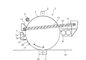
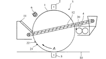
電子写真法を用いた画像形成装置は、一般に、図29に示すように、感光体1に対向して帯電器2、現像装置4、転写器5および除電器(除電ランプ)6を備えている。
【0003】
感光体1が矢印A方向に回転すると、感光体1の表面には帯電器2のコロナ放電により均一な帯電電荷が付与され、図外の露光装置による露光3を受けて静電潜像が形成される。この静電潜像に対して、現像装置4からトナー20が供給され、静電潜像はトナーにより顕像化される。感光体1と転写器5との間には図外の搬送装置により転写用紙10などの転写材が搬送され、転写器5のコロナ放電により感光体1の表面において顕像を形成していたトナーが転写用紙10に転写される。このようにしてトナーを転写した転写用紙10は図外の定着装置による加熱および加圧を受け、トナー画像がその転写用紙10に定着する。
【0004】
上記一連の画像形成工程中の転写工程において、感光体1の表面のトナー像を形成するトナーのすべてが転写用紙10に転写されるわけではない。このため、転写工程を終了した感光体1の表面には、トナー像を形成していたトナーの一部が残留トナー21として残留する。また、感光体1の表面には、コロナ放電による生成物や転写用紙10に含まれる紙粉およびタルクなどの付着物22が付着する。このように感光体1に表面に残留する残留トナー21や付着物22は、以後の画像形成プロセスに悪影響を及ぼし、画質の低下を招く。
【0005】
そこで、転写器5と除電ランプ6との間にクリーニングブレード11を含むクリーニング装置を設け、クリーニングブレード11の先端を感光体1の表面に当接させることにより、転写プロセス終了後の感光体1の表面に付着している残留トナー21および付着物22を感光体1の表面から掻き落とすようにしている。この他にもクリーニング手段としてファーブラシやクリーニングローラなどの部材を感光体の表面に当接させるクリーニング装置が多種類案出されている。
【0006】
上記クリーニング手段によって、感光体表面から除去されたトナーは、トナー除去器にて回収される。この回収されたトナーをすべて廃棄することはトナーの浪費を増大するため、近年では、トナーの浪費を軽減し、その有効利用を図るために、トナー除去器に回収されたトナーを現像装置に搬送して再使用するトナーリサイクル機構を備えた画像形成装置が種々提案されている。図29において、このトナーリサイクル機構は、クリーニングブレード11で除去・回収されたトナーを現像装置4に搬送するためのスクリューコンベア等からなるトナー搬送部材12および搬送に必要なその他の部品で構成される。
【0007】
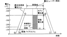
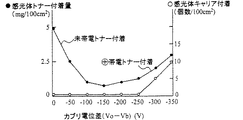
次に、上記の構成からなる画像形成装置におけるカブリ電位差の制御について図30を参照して説明する。同図は、1枚の転写材に対して複写を行ういわゆるシングルモード時の、感光体表面電位および現像バイアス電圧のタイミングチャートを示している。カブリ電位差とは、感光体の表面電位と現像剤坦持体へのバイアス電圧(現像バイアス電圧)の電位差で表される。このカブリ電位差は、不必要にトナーが感光体に付着することのないように適切な値に設定される。図30に示す例では、トナーは−帯電体であり、参照符V1で示す現像電位が高くなる(+側に近づく)ほど、トナー付着量が多くなり、一方で、余剰なトナーは−電位が高くなる(+側に近づく)ほど付着しにくくなる。図の斜線部に示す領域はレーザーによって露光される部分であり、この斜線部にトナーが付着して現像される。
【0008】
ところが、この図30のように正しく制御されるトナーは撹拌によって−帯電された正常なトナーであって、+に帯電した逆帯電トナーや帯電されてない未帯電トナーは、感光体への吸着不良や望ましくない付着を生じることがある。図31は、カブリ電位差に対する逆帯電トナー(+帯電トナー)、未帯電トナーおよびキャリアの感光体付着量を示す図であり、この図から、カブリ電位差が−150Vである時に最も望ましい特性、すなわち未帯電トナーおよび逆帯電トナーの付着を最も少なくできることがわかる。また、望ましくない感光体付着キャリアについても、カブリ電位差が0−250Vの範囲であれば問題が生じないことがわかる。そこで、図30に示す例では、カブリ電位差を−150Vに保って感光体表面電位および現像バイアス電圧の制御を行っている。すなわち、−側に高電位である感光体の表面電位V0 の立ち上げが開始(タイミングa)されてから、表面電位V0 が−150Vまで立ち上がった時点(タイミングb)で、−150Vのカブリ電位差を維持して現像バイアス電圧Vbの印加が開始され、V0 =−550V、Vb=−400Vに到達(タイミングc)し、所定時間が経過すると画像域となり、その画像域内で感光体に現像像が照射され、トナーを付着すべき部分が現像電位V1(−100V)にまで上昇し、画像域が終了すると、カブリ電位差を維持したまま、感光体の表面電位V0 およびバイアス電圧Vbが共に0レベルとなるまで(タイミングe,f)上昇していく。
【0009】
【発明が解決しようとする課題】
しかしながら、トナーリサイクル部は、スクリューコンベアなどの、大規模で機構的に複雑なトナー搬送部材を要し、構成部品の点数の増大や装置大型化を避けることができない欠点があり、また、図30に示すタイミングで制御を行っても、逆帯電トナー(+帯電トナー)や未帯電トナーについては、カブリ電位差を−150Vの最適の値に設定しても0とはならないために感光体表面に付着してしまうという問題がある。特に、図32に示すように、画像形成の進行や、高温多湿などの現像剤の使用される環境が変化すると、逆帯電トナーおよび未帯電トナーの全体に対する割合が相対的に増加し、結果として画質がどんどん劣化してくるという問題があった。
【0010】
また、トナーリサイクル部にてリサイクルされるトナーは、繰り返し使用に伴ってストレスを受けるために、一般に、現像装置の現像槽内に元々あるトナーに比べて諸特性が劣っている。このため、リサイクルトナーが還流されると上記問題は一層顕著となり、現像槽内における逆帯電トナーや未帯電トナーの割合が増えてくると、トナーが量的には十分であるにもかかわらず現像剤中の正常なトナー濃度を透磁率センサが正確に捉えることができず、トナーホッパから必要以上の新トナーが補給されて画像濃度が高くなったり、逆に補給される新トナー量が不足して画像濃度が低下したりするという現象が生じる問題があった。
【0011】
また、特開平7−319356号公報では、金属ローラによって回収したトナーを現像装置に再搬送するリサイクル手段について示し、特開平9−311541号公報では、トナーが過剰に帯電している場合に黒ベタ画像にすることによってその帯電トナーを除去する構成を示しているが、いずれも未帯電トナーや逆帯電トナーの除去については開示していない。また、特開平6−130810号公報では、大規模なトナーリサイクル手段を用いることなくトナーの再利用ができるように、感光体から回収した残留トナーを収納する残留トナー収納部と新規トナー収納部とを連通する構造について示しているが、この公報にも、未帯電トナーや逆帯電トナーを除去することについて開示していない。
【0012】
本発明の第1の目的は、感光体表面に残留している未帯電トナーや逆帯電トナーの帯電不良トナーを容易に除去できるようにすることである。
【0013】
本発明の他の目的は、感光体の回転や画像形成プロセスに影響を与えることなく帯電不良トナーを除去することのできる画像形成装置を提供することにある。
【0014】
本発明のさらに他の目的は、再利用が困難な逆帯電トナーを除去・破棄し、未帯電トナーについてはリサイクルトナーとして再利用することのできる画像形成装置を提供することにある。
【0015】
本発明のさらに他の目的は、感光体表面の帯電不良トナー量が一定以上の場合にのみその除去を行うことのできる画像形成装置を提供することにある。
【0016】
【課題を解決するための手段】
本発明は、上記課題を解決するために次のように構成される。
【0017】
(1)感光体表面に電子写真法により形成された静電潜像へ現像装置でトナーを供給して顕像化する画像形成装置において、
感光体の前回転時または後回転時の非画像形成期間に、感光体の表面電位と現像剤坦持体へのバイアス電圧の電位差で表されるカブリ電位差を可変制御して帯電不良トナーを感光体へ強制付着させる制御部と、
感光体表面に接離可能に設けられ、当接時に感光体表面から前記帯電不良トナーを除去する帯電不良トナー除去用クリーニング手段と、
を設けたことを特徴とする
図31に示すように、カブリ電位差と感光体への帯電不良トナー(未帯電トナーや逆帯電トナー)の付着量はある関係を持っているために、このカブリ電位差を制御することによって感光体へ強制的に感光体へ付着させ、これをクリーニングするものである。この場合、カブリ電位差の制御は感光体の前回転時または後回転時の非画像成期間に行われる。これにより、画像形成プロセスに影響を与えることなく帯電不良トナーを除去することができる。また、帯電不良トナー除去用クリーニング手段は、感光体表面に対して接離可能に設けられているために、帯電不良トナーを除去するのに必要な時だけこのクリーニング手段を感光体表面に当接させることで、感光体表面の磨耗をできるだけ防ぎ、また、当接期間を非画像形成期間内に合わせることによって感光体の回転ムラが生じても画像形成プロセスに影響を及ぼすことがない。
【0018】
(2)前記帯電不良トナー除去用クリーニング手段の下流側に設けられ、現像装置との連通部を備え、該クリーニング手段の離間時に感光体表面から前記帯電不良トナー中の未帯電不良トナーを除去・回収する未帯電トナー回収用クリーニング手段を備え、
前記帯電不良トナー除去用クリーニング手段は、当接時に帯電不良トナー中の逆帯電トナーを除去することを特徴とする。
【0019】
帯電不良トナーのうち未帯電トナーについては、これを回収して現像装置へ還流し再撹拌を行うと正常な帯電特性を示すトナーに転化するので、この未帯電トナー回収用クリーニング手段を設けることによってトナーの利用効率を向上させることができる。一方、逆帯電トナーは除去・廃棄されるために、結局、現像装置内には大部分が正常な帯電特性を示すトナーで占められることになり、カブリのない良好な画質の複写物を安定的に得ることができる。
【0020】
また、現像装置へのリサイクルトナー(未帯電トナー)の搬送を感光体で行うことになるために、大規模なトナーリサイクルシステム(スクリューコンベアなど)が不要となる。このため、トナーに加わる余分なストレスを排除しながら、リサイクルトナーの搬送が最短経路で効率的に行える。
【0021】
本発明の構成では、帯電不良トナー除去用クリーニング手段が感光体表面に当接している状態では、感光体上に付着する未転写トナー、逆帯電トナーおよび異物を該クリーニング手段によって選択的に除去し、このクリーニング手段が感光体表面から離間している状態では、未帯電トナー回収用クリーニング手段によって感光体上に付着する未帯電トナーのみが選択的に除去され回収される。
【0022】
(3)前記制御部は、次の(3−1)と(3−2)の制御を行うことを特徴とする。
【0023】
(3−1)前回転時に、主帯電装置への通電が開始されたときに、感光体が帯電工程対向位置から現像工程対向位置まで進行する時間よりも遅延して前記現像剤坦持体へのバイアス電圧の通電を開始して逆帯電トナーと未帯電トナーをこの順に感光体へ強制付着させる。
【0024】
(3−2)後回転時に、主帯電装置への通電が停止されたときに、感光体が帯電工程対向位置から現像工程対向位置まで進行する時間よりも遅延して前記現像剤坦持体へのバイアス電圧の通電を停止して未帯電トナーと逆帯電トナーをこの順に感光体へ強制付着させる。
【0025】
複写開始が指令されると、まず前回転時サイクルがあり、続いて画像形成サイクルがあり、最後に後回転時サイクルが続く。本発明では、前回転時において帯電不良トナーを感光体に強制付着させ、画像形成期間が終わった後回転時においても上記帯電不良トナーを強制的に感光体上に付着させる。感光体上に強制付着したこれらの帯電不良トナーについては、そのうちの逆帯電トナーについては、逆帯電トナー除去用クリーニング手段によって除去され、未帯電トナーについては未帯電トナー回収用クリーニング手段によって除去・回収される。
【0026】
このように、画像形成の前後において帯電不良トナーを除去し、再使用可能な未帯電トナーについては回収して正常な帯電特性を示すトナーに転化した後再利用するようにしているため、帯電特性の異なる2種類の帯電不良トナーを確実に除去することができると共に、未帯電トナーについては現像装置内にその大部分を回収することができる。このため、トナーの利用効率がよく、しかもカブリのない良好な複写物を安定的に得ることができる。
【0027】
(4)前記逆帯電トナーを除去するときのカブリ電位差は、正規のトナー付着用に設定されるカブリ電位差よりも大きくてキャリア付着を誘発しない程度の電位差に設定され、前記未帯電トナーを除去・回収するときのカブリ電位差は、正規のトナー付着用に設定されるカブリ電位差よりも小さくて正規のトナー付着を誘発しない程度の電位差に設定されることを特徴とする。
【0028】
図31から明らかなように、カブリ電位差が─250Vよりも+電位方向に大きい場合には感光体へのキャリア付着がほとんど問題にならない。したがって、画像形成時のカブリ電位差が─150Vであるとすると、このカブリ電位差を─250Vに制御することによって、感光体上にキャリアが付着しない状態で逆帯電トナー(+帯電トナー)を感光体上に強制付着させることができる。本発明のキャリア付着を誘発しない程度のカブリ電位差とは、図31に示す例では─250V程度の電位差であることをいう。
【0029】
また、カブリ電位差が0Vに近づくほど感光体への未帯電トナー付着量が増加するが、カブリ電位差が0Vに近づくほど、またはこれを越えて感光体表面電位と現像バイアス電圧とが逆転してしまうと正規の帯電特性を持つトナーが感光体上に付着してしまうことになるため、未帯電トナーだけが感光体上に付着するようなカブリ電位差に設定する。
【0030】
これにより、帯電特性の異なる2種類の帯電不良トナーを共に除去することができ、未帯電トナーについては未帯電トナー回収用クリーニング手段によって回収することにより、現像装置内は大部分が正常な帯電特性を示すトナーで占められ、直後に画像形成動作に移行しても、カブリのない良好な複写物を安定的に得ることができる。
【0031】
(5)前記制御部は、複数枚連続の画像形成時に、個々の画像形成期間における紙間の前半期間と後半期間のそれぞれにおいて、未帯電トナーと逆帯電トナーのいずれかが除去され、且つ両方の期間で両方のトナーが除去されるように前記カブリ電位差を制御することを特徴とする。
【0032】
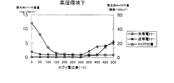
複数枚連続で画像形成を実施する場合、紙間における感光体の表面電位と現像バイアス電圧との電位差は、従来、通常の画像形成期間と同じ値に設定されている。しかしながら、この紙間を利用して、その前半期間と、後半期間とでカブリ電位差を切り換え制御することによって、各々の期間で帯電特性の異なる帯電不良トナーを感光体上へ強制付着させることができる。したがって、連続複写を行うにあたって、画質を維持するために帯電不良トナーを排出する期間を途中に設けなくてもよいから、機械の利用効率や画像形成の速度を特に低下させることなく良好な画質を維持することができる。
【0033】
(6)前記帯電不良トナー除去用クリーニング手段は、感光体表面の付着物に応じて切り換えることを特徴とする。
【0034】
帯電不良トナー除去用クリーニング手段を必要な場合以外は感光体に接触させないようにすることで、回収・除去部材の不必要な消耗や、感光体の損傷、回収・除去部材との接触に伴う感光体の回転抵抗が抑制される。
【0035】
(7)前記未帯電トナー回収用クリーニング手段の感光体への当接力は、前記帯電不良トナー除去用クリーニング手段の当接力よりも小さく設定されていることを特徴とする。
【0036】
未帯電トナー回収用クリーニング手段の感光体への当接力を相対的に小さくすることによって、このクリーニング手段で除去・回収して現像装置へ還流して再利用される未帯電トナーへの不必要なストレスが低減される。
【0037】
(8)上記(1)において、感光体表面の転写後の残留未転写トナーを感光体から除去・回収し、リサイクルトナーとして現像装置へ搬送する手段を備えたリサイクルトナー回収用クリーニング手段を、さらに備えたことを特徴とする。
【0038】
本発明では、転写後の感光体表面に残留する未転写トナーをクリーニングブレード等によって除去して回収し、これをリサイクルトナーとして現像装置へ搬送するスクリューコンベア等の搬送手段を備えたリサイクルトナー回収用クリーニング手段を設けたものであって、これによれば、リサイクルトナー回収用クリーニング手段によって、従来の複写装置と同様に残留未転写トナーをリサイクルトナーとして再利用できると共に、未帯電トナーや逆帯電トナーなどの帯電不良トナーを除去することができるから、現像装置内では大部分が正常な帯電特性を示すトナーで占められることになり、カブリのない良好な画質の複写物を安定的に得ることができる。
【0039】
(9)上記(8)において、前記制御部は、前回転時にカブリ電位差を可変制御し、
前記帯電不良トナー除去用クリーニング手段は、感光体停止時に感光体表面に当接され、帯電工程対向位置が該クリーニング手段を通過した後で勝つ画像形成前に離間されることを特徴とする。
【0040】
帯電不良トナー除去用クリーニング手段が感光体表面に当接した時における感光体の回転負荷に伴う回転ムラが発生しても、この当接動作は画像形成前に解除されて該クリーニング手段が画像形成時には感光体表面から離間された状態となるために、画像への影響を及ぼすこともなく、また、複写効率を損なうことなく良好な画像の複写物を安定していることができる。
【0041】
(10)上記(8)において、前記帯電不良トナー除去用クリーニング手段は、画像形成後の感光体停止後に離間され、次の感光体回転までの間は離間状態で待機することを特徴とする。
【0042】
帯電不良トナー除去用クリーニング手段は、次の感光体回転までの間は離間状態で待機するために、クリーニングブレードの永久変形を防止することができ、これにより長期にわたり安定したクリーニング特性を期待することができる。
【0043】
(11)前記帯電不良トナー除去用クリーニング手段と前記リサイクルトナー回収用クリーニング手段は、それぞれクリーニングブレードを有し、前記帯電不良トナー除去用クリーニング手段のブレード硬度は、前記リサイクルトナー回収用クリーニング手段のブレード硬度よりも低く設定されていることを特徴とする。
【0044】
リサイクルトナー回収用クリーニング手段のクリーニングブレードは、一般には常時感光体表面に対して当接状態にあるが、このクリーニングブレードの硬度よりも帯電不良用トナー除去用クリーニング手段のクリーニングブレードの硬度を低くすることによって、感光体への機械的ストレスの低減を図り、これにより膜質にダメージを与えることなく安定したトナー除去を行うことが可能となる。
【0045】
(12) 前記帯電不良トナー除去用クリーニング手段のクリーニングブレードの感光体へのくい込み量は、前記リサイクルトナー回収用クリーニング手段のクリーニングブレードのくい込み量よりも少なく設定されていることを特徴とする。
【0046】
上記(11)と同様に、感光体への機械的ストレスの低減を図ることによって、膜質へダメージを与えることなく安定したトナー除去を行うことが可能となる。
【0047】
(13)前記帯電不良トナー除去用クリーニング手段のクリーニングブレードの突き出し量は、前記リサイクルトナー回収用クリーニング手段のクリーニングブレードの突き出し量よりも少なく設定されていることを特徴とする。
【0048】
本発明も(11)および(12)と同様に、感光体への機械的ストレスの低減を図る。また、帯電不良トナー除去用クリーニング手段のクリーニングブレードの接触動作切り換え時におけるブレード反転現象を防止することも可能となる。
【0049】
(14)前記帯電不良トナー除去用クリーニング手段は、感光体へ強制付着させた帯電不良トナーの付着開始部が当接開始となるように当接制御されることを特徴とする。
【0050】
帯電不良トナー除去用クリーニング手段のクリーニングブレードの接触動作切り換え時におけるブレード反転現象を防止することが可能となる。
【0051】
(15)前記帯電不良トナー除去用クリーニング手段のクリーニングブレードの全長は、前記リサイクルトナー回収用クリーニング手段のクリーニングブレードの全長よりも短く設定されていることを特徴とする。
【0052】
感光体に対し離間・当接を繰り返す際に発生する帯電不良トナー除去用クリーニング手段のブレード端部からのすり抜けトナーを確実にリサイクルトナー回収用クリーニング手段のクリーニングブレードで回収可能となり、すり抜けトナーによる機内汚染を未然に防止することが可能となる。
【0053】
(16)上記(1)において、感光体表面の帯電不良トナーを検出する光学センサを有し、前記制御部は、該光学センサの検出結果に基づいてカブリ電位差の可変制御を行うことを特徴とする。
【0054】
本発明は、光学センサを用いることによって、必要な場合にのみカブリ電位差の可変制御を行い帯電不良トナーを除去するようにしたものである。これにより、機械の利用効率や画像形成の速度を大きく低下させることなく、カブリのない良好な画質の複写物を安定的に得ることができる。
【0055】
(17)前記光学センサは、画像形成累積枚数が設定値以上になったときにのみ帯電不良トナーを検出することを特徴とする。
【0056】
複写累積枚数がすくない場合には図32に示すように帯電不良トナーの全体に対する分布はそれほど増えることがない。そこで、複写累積枚数が設定以上となった時にのみ光学センサにより帯電不良トナーが所定値以上かどうかを検出するようにする。これにより、機械の利用効率を損なうことなく、リサイクルトナーとして適さない帯電不良トナーを強制除去することが可能となる。
【0057】
(18)前記光学センサは、現像装置の累積稼働時間が設定値以上になったときにのみ帯電不良トナーを検出することを特徴とする。
【0058】
同様に、現像装置の累積可動時間が設定以上となった時にのみ帯電不良トナーの検出を実行することにより、複写装置の使用頻度に関わらず安定したタイミングで帯電不良トナーの強制除去を行うことが可能となる。
【0059】
(19)前記光学センサは、非画像形成時で且つ前回転時または後回転時において検出動作を行い、前記制御部は該センサの検出結果に基づいてカブリ電位差の可変制御を行うととともに、前記帯電不良トナー除去用クリーニング手段は該センサの検出結果に基づいて感光体表面への接離制御が行われることを特徴とする。
【0060】
非画像形成時の前回転時または後回転時において、上記検出動作を行うことによって、機械の利用効率が悪くなったり画像形成の速度が特に低下することもなくなる。
【0061】
(20)感光体表面の顕像を用紙に転写した後、これを剥離するための剥離チャージャを有し、
前記制御部は、前記帯電不良トナー除去用クリーニング手段が感光体に当接しているとき、該剥離チャージャの電圧を制御して感光体表面上の残留電位のキャンセルを行うことを特徴とする。
【0062】
帯電不良トナーの除去前に感光体表面上の残留電位のキャンセルを行うことによって、該帯電不良トナーの除去を容易に行うことができ、帯電不良トナーによる機内汚れを未然に防止できる。
【0063】
(21)帯電工程位置の直前に配置され、感光体表面の残留電位をキャンセルするための除電ランプを有し、
前記制御部は、前記帯電不良トナー除去用クリーニング手段が感光体に当接しているとき、該除電ランプの光量を制御して感光体表面上の残留電位のキャンセルを行うことを特徴とする。
【0064】
上記(20)と同様に、感光体に付着させた帯電不良トナーの除去を容易に行うことができる共に、帯電不良トナーによる機内汚れを未然に防止することができる。
【0065】
(22)前記除電ランプの光量は、複写プロセス時に使用する除電ランプ光量よりも暗く設定することを特徴とする。
【0066】
上記のように、除電ランプの光量を通常よりも暗く設定することによって、感光体に過度の光疲労を与えることなく、感光体上に付着させた帯電不良トナーの除去を容易に行うことができると共に、帯電不良トナーによる機内汚れを未然に防止することができる。
【0067】
(23)前記制御部は、帯電不良トナー中の未帯電トナー除去時には前記カブリ電位差を画像形成時のカブリ電位差よりも小とし、帯電不良トナー中の逆帯電トナー除去時には前記カブリ電位差を画像形成時のカブリ電位差よりも大とすることを特徴とする。
【0068】
リサイクルトナーとして適さない未帯電トナーおよび逆帯電トナー双方を強制的に除去することによって、現像装置内は大部分が正常な帯電特性を示すトナーで占められることになり、これによりカブリのない良好な画質の複写物を安定的に得ることができる。
【0069】
(24)前記制御部は、前記カブリ電位差を周囲環境状況により異なった値に可変制御することを特徴とする。
【0070】
図31に示すカブリ電位差特性は湿度や温度などの周囲環境状況によって変動するために、本発明によれば、周囲環境条件に関わらず、帯電不良トナーのみを適切に感光体上に付着させることが可能となり、キャリア付着や機内汚染を防止することができる。
【0071】
(25) 前記制御部は、感光体の表面電位を画像形成時の表面電位以下にすることでカブリ電位差の可変制御を行うことを特徴とする。
【0072】
低電位にて帯電不良トナーのみを適切に感光体上に付着させることによって、感光体上に付着させたトナーの除去を容易に行うことができると共に、キャリア付着や機内汚染を防止することができる。
【0073】
(26)前記制御部は、画像形成装置本体の使用頻度に応じて感光体の表面電位を制御することでカブリ電位差の可変制御を行うことを特徴とする。
【0074】
輻射装置の使用頻度、つまり現像剤の帯電レベルに応じて感光体の帯電電位を決定することで、帯電不良トナー除去時において、現像剤の状態に関わらずキャリア付着および機内汚染を防止することができる。
【0075】
(27)前記制御部は、前記感光体の表面電位と現像剤坦持体へのバイアス電圧をパルス幅変調で制御することで前記カブリ電位差を可変制御するようにした。
【0076】
容量性の負荷である感光体および現像剤坦持体の電位は、所定の電流を通電する時間に比例するので、その通電時間を制御するパルス幅変調によって、容易に所望の電位を得ることができる。感光体の表面電位は、それに対向するグリッドへの印加電圧と同電位となり、現像剤坦持体の電位も現像バイアス電圧と同電位となる。現像バイアス電圧、感光体表面電位共に一定の傾きを維持しながら目標値へ到達させるためには、単純なオン−オフ制御では瞬時に到達して垂直状の変化となり制御が困難であるが、ぱパルス幅変調では、時間経過と共に電位変化させることができるので、電源装置の制御が高精度且つ効率的に行われ画像形成装置の性能向上につながる。
【0077】
【発明の実施の形態】
以下、本発明の実施形態について説明する。
【0078】
〔第1の実施形態〕
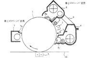
図1は、本発明の第1の実施形態に係る画像形成装置における画像形成部の概略構成図である。
【0079】
画像形成装置は、図1に示すように、感光体1に対向して帯電器2、露光装置3、現像装置4、転写器5および除電器6を備えており、これらの動作は従来の画像形成装置と同じである。
【0080】
また、上記画像形成装置は、クリーニング手段として第1のクリーニング装置(帯電不良トナー除去用クリーニング手段)7、および、第2のクリーニング装置(未帯電トナー回収用クリーニング手段)8を有している。第1のクリーニング装置7は、転写器5の下流に配置される。第2のクリーニング装置8は、第1のクリーニング装置7の下流、且つ、除電器6の上流に配置されると共に、ここで回収したトナーを現像装置4に戻して再利用可能となるように、現像装置4に対してトナーダクト9によって連通されている。また、少なくとも第1のクリーニング装置7は、感光体表面に対してクリーニングブレード接離可能となっている。なお、第2のクリーニング装置8においても感光体表面に対してクリーニングブレードを接離可能とすることが可能であり、この場合、第1のクリーニング装置7が感光体に当接している状態で第2のクリーニング装置8を待機状態とすることによって、回収・除去部材の不必要な消耗や感光体の損傷、回収・除去部材との接触に伴う感光体の回転抵抗が抑制される。
【0081】
上記の画像形成装置では、現像装置4内に存在する未帯電トナーや逆帯電トナーを、バイアス電圧を調整することによって選択的に感光体に強制付着させ、強制的に現像装置外へ排出することが可能である。未帯電トナーは、再度現像装置へ送り込んで撹拌することによって正常に帯電する可能性があるために、第2のクリーニング装置8によって回収される(この時第1のクリーニング装置7は感光体に対し離間される)。また、逆帯電トナーは正常に帯電する可能性が低いために、感光体に対し当接状態とされた第1のクリーニング装置7によって除去され、廃棄される。
【0082】
また、転写工程において生じる残留トナー(未転写トナー)は、紙粉やタルクなおの不純物を含んでおり、これを現像装置4へ還流することは不都合であるので、該残留トナーは第1のクリーニング装置7によって除去され、廃棄される。なお、本実施形態では、上記のように第1のクリーニング装置7によって逆帯電トナー除去と残留トナーの除去とを兼用するようにしている。後述の実施形態では、残留トナーを除去・ 回収して現像装置4に還流させるリサイクルトナー回収機構を設けている。
【0083】
次いで、未帯電トナーや逆帯電トナーからなる帯電不良トナーを、バイアス電圧を調整することで選択的に感光体に付着させ、強制的に現像装置外へ排出するための構成について説明する。
【0084】
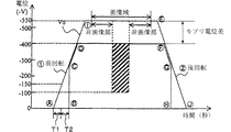
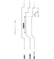
図2は、上記画像形成装置の画像形成動作を説明するためのタイミングチャートである。本実施形態では、トナーの特性は、図31に示すように、カブリ電位差が−150Vで未帯電トナーおよび+帯電トナーの付着が最小となる帯電特性を備えており画像域でのカブリ電位差はこの−150Vに設定されているものとする。また、画像域における感光体の表面電位V0 は−550Vであり、現像ローラ4c(図1参照)への現像バイアス電圧Vbは−400Vである。また、この図2に示すタイミングチャートは、1枚の転写材10へ複写を行うシングルモード時の動作を示している。
【0085】
図2において、複写動作が開始すると、現像ローラ4cの前回転が開始され、感光体1の表面電位V0 の立ち上げが開始されてから(タイミングA)、時間T1が経過して、表面電位V0 が−150Vに到達しても現像ローラ4cへのバイアス電圧Vbの立ち上げは開始されず、さらに遅延時間T2だけ経過した時点(タイミングB)からバイアス電圧Vbの立ち上げが開始される。このタイミングBでは、カブリ電位差は−250Vで、図31で示すように、+帯電トナー(逆帯電トナー)9が感光体に付着し、キャリアが付着しない電位差となっている。以降、V0 −Vb=−20Vに到達する(タイミングC)までの期間には、+帯電トナーを感光体に付着させることができる。
【0086】
その後、バイアス電圧Vbが所定の電圧の−400Vに到達する(タイミングD)まで、前記−20Vのカブリ電位差が維持され、この間に、図31から明らかなように、未帯電トナーが感光体に付着することになる。
【0087】
感光体表面電位V0 が−550Vに到達すると(タイミングI)、画像域となり、その間に原稿像の露光が行われる。画像形成が終了すると、感光体1が後回転となり、表面電位V0 の低下が開始される(タイミングE)。その後、カブリ電位差が前記−20V程度となると、バイアス電圧Vbの低下も開始され(タイミングF)、その後、所定期間に渡ってカブリ電位差が−20V程度で維持され、この間に、タイミングC〜D間と同様に、未帯電トナーが感光体へ付着する。
【0088】
感光体表面電位V0 が前記−250Vに到達すると(タイミングG)、バイアス電圧Vbは0となるまで(タイミングH)急激に立ち下げられ、表面電位V0 が0となるまで(タイミングJ)のタイミングG〜J間でにおいて、前記タイミングA〜C間と同様に、+帯電トナーが感光体に付着することになる。
【0089】
なお、前記タイミングC〜D間およびF〜G間で、V0 −Vb=−20Vとなっているが、これは感光体の使用条件、すなわち、印刷枚数および温度や湿度などを考慮し、表面電位V0 とバイアス電圧Vbとが逆転することによって生じる正規の帯電トナーの付着を抑えるためであり、この−20Vのカブリ電位差は、上記感光体の使用条件によって適宜変更される。
【0090】
このようにして、1枚の転写材に対して複写指令を出した後、前回転時においては、タイミングCまでの期間において+帯電トナーを感光体に強制付着させ、タイミングCからタイミングDまでの期間において未帯電トナーを感光体に強制付着させる。また、画像形成を終了して後回転時に入った時には、タイミングGまでの期間において未帯電トナーを感光体に強制付着させ、タイミングGからタイミングJまでの期間において+帯電トナーを感光体に強制付着させる。なお、T1とT2の加算時間は、複写開始時の帯電器対向位置(帯電器2が対向する感光体位置)が現像装置対向位置(現像ローラ4cが対向する感光体位置)まで進行する時間よりも長くなるように設定されている。同様に、後回転時におけるタイミングGからタイミングJまでの時間は、帯電器対向位置が現像装置対向位置まで進行する時間よりも長い時間に設定されている。
【0091】
一方、第1のクリーニング装置7の接離制御は以下のようにして行われる。
【0092】
感光体1が駆動開始前にクリーニングブレード7aが感光体表面に当接するように制御され、タイミングD以降で少なくとも画像域の先端が第1のクリーニング装置7に至る間に、該クリーニングブレード7aが感光体表面から離間されるように制御される。また、後回転時においては、画像域の後端が転写器5の対向位置を過ぎたタイミングでクリーニングブレード7aが感光体表面に当接するように制御され、感光体1の駆動が停止した以降に該クリーニングブレード7aが感光体表面から離間するように制御される。
【0093】
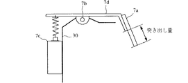
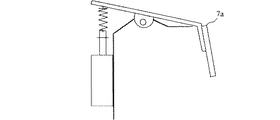
図3、4は第1のクリーニング装置7の一部構成図である。
【0094】
クリーニングブレード7aは、支点7bを中心に電磁ソレノイド7cの通電によって回動する支持板7dの一端に取り付けられており、このソレノイド7cのON−OFF動作によって、クリーニングブレード7aを感光体1の表面に対して当接または離間できるようになっている。図3はソレノイド7cがONすることにより当接した状態、図4はOFFすることにより離間した状態をそれぞれ示している。ソレノイド7cがOFF状態ではクリーニングブレード7aが離間しているために、複写機の電源をOFFしているときにはクリーニングブレード7aが必ず離間することになるため、同ブレード7cが変形することを防ぐことが出来る。
【0095】
なお、感光体の使用条件のうち、高湿環境下および低湿環境下におけるカブリ電位差特性を図5および図6にそれぞれ示す。このように、湿度の影響によってカブリ電位差に対する未帯電トナーおよび逆帯電トナーの付着量が変動する。この変動を考慮してカブリ電位差の微調整を行うことが可能である。具体的には、湿度センサを設け、このセンサ出力に基づいて現像バイアス電圧Vbの補正などの制御を行う。
【0096】
次に、制御部における、上記カブリ電位差の可変制御を行う回路構成について図7〜図9を参照して説明する。
【0097】
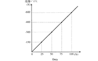
図7は、感光体の表面電位、すなわち帯電器2のグリッドに与える電位を制御する回路構成を示している。図示はしていないが、現像バイアス電圧Vbの電圧制御回路も図7に示す回路と同様な構成にある。ここでは、感光体1の表面電位を制御する回路について説明する。制御部Sは、電位制御のためのプロセスを行う図外のCPUと共に、メモリM、カウンタCNT、パルス発生器PG、AD変換器ADC、および反転回路を備えている。この回路は、感光体1の表面電位を均一にする帯電電圧を発生させるのに、出力電圧Voutが一定になるように制御する。すなわち、出力電圧Voutを2つの検出抵抗R、rで分圧し、Vout×r/(r+R)で得られる電圧を制御部Sの演算回路にフィードバックし(反転回路にフィードバックし)、ADCでAD変換された値をCNTによってメモリMに予め設定された目標値と比較し、これが等しくなるようパルス発生器PGをPWM制御する。具体的には、AD変換値が目標値よりも大きい場合にはPWM信号のDUTYを小さくし、目標値よりも小さい場合にはPWM信号のDUTYを大きくする。そして、そのPWM信号でトランジスタをON/OFFすることによって出力を得る。また、PWM信号のDUTYはトランスTが磁気飽和しないレベルで制限をしている。この回路を、現像バイアス電圧Vbの制御に使用する場合には、回路出力端子を現像バイアス用の端子に接続すればよい。
【0098】
上記の構成で、感光体1の表面電位を一定の傾きに維持しつつ所定の電位−550Vに到達させるためには、メモリMに設定する目標値を少しずつ変えながら上記PWM制御を行う。なお、図8は感光体表面電位とグリッド印加電圧との関係を示しているが、同図に示すように、グリッド印加電圧と感光体表面電位はほぼ同一である。また、図9は現像バイアス電圧VbとPWM信号のDUTYの関係を示しているが、例えば−400Vの現像バイアス電圧Vbを得るためにはDUTY100%であればよいことがわかる。
【0099】
このように、本実施形態では現像バイアス電圧Vbおよび感光体表面電位V0 共にパルス幅変調(PWM変調)を行っているが、これを単純にON−OFF制御すると、瞬時に目標電位へ到達してしまい電位変化が垂直状の変化となって電圧制御が困難である。これに対し、PWM制御であると、時間経過と共に一定の傾きを維持しながら比例関係で電位変化をさせることが容易であるために、電源装置の出力制御を高精度且つ効率的に行うことができ、画像形成装置の性能向上につながる。
【0100】
以上のようにして、帯電不良トナーを、その不良特性に応じて感光体1に付着させ、第1のクリーニング装置7によって強制的にこれを除去し、第2のクリーニング装置8によって回収されないようにしているため、現像装置4内では大部分が正常な帯電特性を示すトナーで占められる。これにより、カブリのない良好な画質の複写物を安定的に得ることができる。
【0101】
〔第2の実施形態〕
本発明の第2の実施形態では、複数枚連続の画像形成を行う時に、個々の画像形成期間においてカブリ電位差の制御が行われる。
【0102】
図10は、このカブリ電位差の制御を行うタイミングチャートを示している。同図のA〜Fの各タイミングは図2のA〜Fの各タイミングに類似するタイミングである。
【0103】
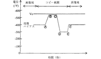
複数枚連続の画像形成を行うモード、すなわちマルチモードでは、感光体の表面電位V0 は、上述の−550Vの一定値で保持されている。一方、現像バイアス電圧Vbは、従来の装置であったなら−400Vで一定に保持されているところを、この実施形態では−530Vから─300Vの範囲で変化させている。すなわち、個々の画像形成期間における紙間を前半期間と後半期間にわけ、前半期間においては、タイミングA−B間において現像バイアス電圧Vbを−400Vから−530Vまで変化させ、この状態をタイミングB−タイミングC間で保持する。また、後半期間においては、タイミングC−タイミングD間において現像バイアス電圧Vbを−530Vから−300Vまで変化させ、この状態をタイミングD−タイミングE間保持し、次の画像域の直前のタイミングE−タイミングFにおいて現像バイアス電圧Vbを−400Vに戻す。このような制御によって、コピー紙間の前半期間のタイミングB−タイミンングCの期間においては未帯電トナーが除去され、後半期間のタイミングD−タイミングE間では逆帯電トナーが除去される。なお、クリーニグブレード7aは、タイミングAの前で当接制御され、タイミングFの前で離間制御される必要がある。
【0104】
〔第3の実施形態〕
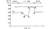
本発明の第3の実施形態では、第2の実施形態と同様に、複数枚連続の画像形成を行う時に、個々の画像形成期間に置いてカブリ電位差の制御が行われる。図11は、このカブリ電位差の制御を行うタイミングチャートを示している。図10に示すタイミングチャートと相違する点は、コピー紙間の前半期間において現像バイアス電圧Vbを−400Vから−300Vに上昇させて逆帯電トナーを除去し、後半期間において−530Vに低下させることによって未帯電トナーを除去するようにしている点である。なお、図10に示す第3の実施形態では、タイミングCからタイミングEにかけてクリーニングブレード7aが感光体1の表面に当接し、図11に示す第4の実施形態では、タイミングAからタイミングCにかけてクリーニングブレード7aが感光体1の表面に当接する。
【0105】
また、未帯電トナーを回収する第2のクリーニング装置8のクリーニングブレード8aの感光体1への当接力は、第1のクリーニング装置7のクリーニングブレード7aの感光体1への当接力よりも小さく設定されている。このように、クリーニングブレード8aの当接力をクリーニングブレード7aの当接力よりも低めの設定とすることによって、クリーニングブレード8aで除去されて再使用に供される未帯電トナーへの不必要なストレスをできるだけ低減することができる。
【0106】
また、第2のクリーニングの装置8のクリーニングブレード8aについては、第1のクリーニング装置7のクリーニングブレード7aと同様に、感光体1の表面への当接又は離間を感光体表面の付着物に応じて切り換えることも可能である。即ち、例えば、図2に示すシングルモード時の動作では、タイミングCからタイミングDにかけて及びタイミングFからタイミングGにかけての未帯電トナーを除去する期間に感光体1表面の未帯電トナーが除去されるよう適切なタイミング制御をしてブレード8aを感光体1の表面に当接する。また、図10や図11のマルチモード時の動作においては、タイミングBからタイミングCにかけて又はタイミングDからタイミングEにかけて感光体表面上の未帯電トナーが除去されるよう、ブレード8aを適切に制御して感光体1の表面へ当接させる。このような制御を行うと、第1のクリーニング装置7のクリーニングブレード7aが感光体1に当接している状態では、第2のクリーニング手装置8のクリーニングブレード8aが待避状態(離間状態)となり、第2のクリーニング装置8のクリーニングブレード8aを必要な場合以外は感光体1に接触させないように制御することとなり、回収・除去部材の不必要な消耗や、感光体1の損傷、回収・除去部材との接触に伴う感光体の回転抵抗を抑制することができる。
【0107】
〔第4の実施形態〕
図12は、本発明の第4の実施形態を示している。
【0108】
図29に示す従来の構成と相違する点は、この実施形態では、感光体1上の残留未転写トナーを感光体から除去・回収するためのリサイクルトナー回収用クリーニング装置11の上流側に、感光体表面から帯電不良トナーを除去する第1のクリーニング装置(帯電不良トナー除去用クリーニング装置)7を配置した点である。上記第1のクリーニング装置7のブレード7aは、図3および図4に示すように、支持板7dに取り付けられ、支点部7bを中心に電磁ソレノイド7cの通電により回動し、感光体1に対し当接・離間状態に切り換え可能となるように構成されている。画像形成装置自体の他の構成については、図29に示す従来のものと同様であるが、この実施形態では、図13に示すように、給紙系・プロセス系・搬送定着系のそれぞれが、単独で駆動可能となるようにこ個々の系に駆動モーターが設けられている。カブリ電位差の制御については、上記第1〜第3の実施形態と同様に、−150Vで制御される(画像域でのカブリ電位差)。なお、画像域における感光体1におけるV0 は−600Vに設定され、その時に現像ローラー4Cへのバイアス電圧Vbは−450Vに設定される。
【0109】
次に、この実施形態において帯電不良トナーを除去するための制御フローについて、図14〜図17を参照して説明する。
【0110】
図14は、帯電不良トナーを除去するための制御フローを示している。
【0111】
複写開始の指令がなされると、先ず、累積可動時間αtの参照を行い、予め設定された時間(例えば3600秒)以上であるかどうかでの判断を行い、その結果が設定時間未満の場合、図15に示すように、通常のカブリ電位差をもって、感光体表面電位及び現像バイアス電圧の立ち上げと立ち下げを行う。図14では、この制御をプロセスシーケンスAを採用することによって行う。
【0112】
・プロセスシーケンスA
このシーケンスでは、感光体表面電位V0 及び現像バイアス電圧Vbの立ち上げ時において未帯電トナーの除去を行う。即ち、ST2でクリーニングブレード7aを感光体1に当接し、その後t1経過した後に(ST3)各駆動系が回転を始め(ST4)、感光体表面電位V0 及び現像バイアス電圧Vbのカブリ電位差が−150Vで維持されるように立ち上げ動作がなされる。その後、t2経過後に電磁ソレノイド7c(図3及び図4参照)の通電が遮断され、クリーニングブレード7aが感光体1から離間する方向に回動する(ST6)。上記t2は、画像形成プロセスが実行される前で、且つ、帯電器2の直下に位置する感光体1の位置がクリーニングブレード7aに到達するまでの時間に設定されており、帯電器2の直下の帯電部分が現像装置4を通過する際(この部分はカブリ電位差が0Vとなっている)におこる未帯電トナーの付着を除去するために設定される時間である。なお、図17は全体のタイミングチャートである。この後、図示しない画像形成プロセスが実行される。
【0113】
・プロセスシーケンスB
累積可動時間がαt以上の場合に実行される。プロセスシーケンスBでは感光体表面電位及び現像バイアス電圧の制御を図16に示すように行う。
【0114】
まず、ST10〜ST14において、上記ST2〜ST6と同じ制御を行い、立ち上げ直後の感光体未帯電部分へ付着した未帯電トナーの付着を除去する。
【0115】
続いて、画像形成プロセスが終了すると、現像バイアス電圧Vbを−450Vから−300Vに切り換える。これにより、カブリ電位差を−300Vに設定する。カブリ電位差が−300Vでは、図31から明らかなように、逆帯電トナー(+帯電トナー)が感光体1へと移行する。ST15において、この現像バイアス電圧を切り換えた後現像ローラー4cの位置がクリーニングブレード7aへ到達するまでの時間t4経過するのを待ち、電磁ソレノイド7cへの通電を行ってこのクリーニングブレード7aを感光体1へと再び当接して、感光体上に付着している逆帯電トナー(+帯電トナー)を除去する(ST16、ST17)。次に、ST18において感光体表面電位V0 を−600Vから−300Vに切り換えてカブリ電位差を0Vに設定し、未帯電トナーを感光体表面へと移行させた後、感光体表面電位・現像バイアス電圧・駆動系を停止させる(ST19)。クリーニングブレード7aは、プロセス駆動系停止の指令発生から、t5経過(感光体停止後)に電磁ソレノイド7cへの通電が遮断されることによって感光体1から離間する(ST20、ST21)。この後、累積可動時間αtをリセットする(ST22)。
【0116】
上記の手順により図16に示すように、感光体の後回転時の時間TAにおいて逆帯電トナーが除去され、時間TBにおいて未帯電トナーが除去される。このようにして除去された帯電不良トナーは、第1のクリーニング装置7内に設けられている搬送手段7bによって、図示しない回収容器へと搬送され、廃棄トナーとして蓄えられる。
【0117】
クリーニングブレード7aを上記のように、長時間(累積可動時間がαt以上となる時間)開放された後、感光体1が停止状態にあるST10で当接動作を行わせることによって、当接時におけるブレードの反転を防止することができるが、更にこのブレードを、以下の設定
・ブレード突き出し量(図3参照)を8mm以下に設定
・ブレード食い込み量を1mm以下に設定
・ブレードのゴム硬度を60度以下に設定
とすることによって、感光体1の感光膜にダメージを与えることがなく、また、当接時におけるブレード反転現象を確実に防止できることがわかった。
【0118】
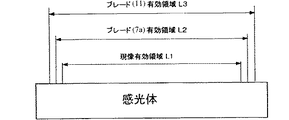
また、クリーニングブレード7aの当接・離間動作に伴い、どうしてもこのブレードの下流側にトナーのすり抜けを発生してしまうことがある。そこで、このクリーニングブレード7aの設定をL1<L2<L3
・L1 現像有効領域
・L2 クリーニングブレード7a有効領域
・L3 残留未転写トナー回収用のクリーニングブレード11有効領域
とすることによって、クリーニングブレード7a、特にその両端近傍からのすり抜けが発生した場合でも、その下流側にあるクリーニングブレード11によって確実にその回収を行うことができる。これによって、すり抜けトナーによる機内汚染を未然に防止することができる(図18参照)。
【0119】
上記実施形態のように、駆動源が給紙系、プロセス系、搬送・定着系にそれぞれ個別に配された画像形成装置においては、最終画像領域の現像工程が終了した直後より帯電不良トナーを除去するプロセスを実行することが可能となり、これにより複写効率を損なうことなく帯電不良トナーを除去することが可能になるが、少なくとも感光体と定着器が同一の駆動源で駆動される画像形成装置においては、クリーニングブレード7a当接時における感光体1への負荷変動は定着器へ伝達され、定着工程時での画像滲みなどの不具合が発生してしまう恐れがある。そこで、少なくとも感光体1と定着器が同一駆動源で駆動される画像形成装置においては、転写紙排出後より、現像バイアス電圧と感光体表面電位の切り換えによるカブリ電位差制御を行うことにより、帯電不良トナーを除去する。このようにすれば、複写効率は若干低下してしまうが、定着トラブル等を起こさずに帯電不良トナーの除去を確実に行うことが可能である。
【0120】
なお、この第4の実施形態においても、感光体表面電位V0 及び現像バイアス電圧Vbの制御は図7に示すようにパルス幅変調方式によって行われる。
【0121】
〔第5の実施形態〕
図19は本発明の第5の実施形態を示している。上記図12に示す第4の実施形態と相違する点は、帯電不良トナー除去用の第1のクリーニング装置7の上流側に光学センサ13を配置している点である。他の画像形成装置自体の構成については、図12に示すものと同様である。また、使用するトナーの特性についても、カブリ電位差が−150Vで未帯電トナー及び逆帯電トナー(+帯電トナー)の付着が最小となる特性を持ち、画像領域でのカブリ電位差はこの−150Vに設定される。なお、感光体1の表面電位V0 は−600Vに設定され、現像ローラー4cへのバイアス電圧Vbは−450Vに設定される。
【0122】
上記光学センサー13は複写開始指令後に、このセンサー出力が一定以上の場合にのみ帯電不良トナー除去用のプロセスを実行するのに用いられる。光学センサー13の特性は、図20に示している。同図より、感光体1上の付着トナー量が1mg/100cm2 以上のところに変曲点を有し、これにより、しきい値を3Vとしてセンサー出力電圧を判定する。センサー出力電圧が3V以上の場合に、帯電不良トナー除去用のプロセスを実行し、未満の場合には同プロセスを行わない。これにより、複写指令毎に毎回帯電不良トナーを除去するプロセスを実行するということが無くなるため、機械の利用効率を損なわず、リサイクルトナーとして適さない帯電不良トナーを強制的に除去することが可能となる。
【0123】
以下、図21を参照して、この実施形態の画像形成装置のカブリ電位差制御動作を説明する。
【0124】
まず、ST30において、複写開始指令と共に前回複写終了時の、光学センサー13による帯電不良トナー検出結果を参照する。帯電不良トナーを検出していた場合には、フラグがONである。フラグがON(帯電不良トナーを検出していた場合)の場合はプロセスシーケンスEを採用する。このプロセスシーケンスEのタイミングチャートは第4の実施形態のプロセスシーケンスB(図16)と同様である。
【0125】
・プロセスシーケンスE
このプロセスシーケンスEのタイミングチャートは図22の通りである。このプロセスシーケンスEでは、感光体表面電位Vo 及び現像バイアス電圧Vbの立ち上がりは、図30に示す従来の場合と同様であり、カブリ電位差−150Vを維持させて立ち上げ動作を行い画像形成プロセスへと移行する。
【0126】
図21のST40において画像形成が終了すると、第1のクリーニング装置7のブレード7aを感光体1に当接させる(ST41)。すでに述べたように、ブレード7aは、ソレノイド7cをオンすることによって感光体1に当接させることができる(図3参照)。ブレード7aを感光体1に当接させるとともにST42において現像バイアス電圧Vbを−250Vに切り換える。これによりカブリ電位差は−350Vとなり、図31に示すように現像装置4内の逆帯電トナー(+帯電トナー)が感光体1へと移行する。この時間はt5である。この時間が経過すると、次に感光体表面電位を−250Vに切り換える(ST44)。これにより、カブリ電位差が0Vとなり、図31に示すように現像装置4内の未帯電トナーが感光体1へと移行する。この時間はt6である(ST45)。
【0127】
以上の処理によって、図22の時間TAにおいて逆帯電トナー(+帯電トナー)が感光体1から除去され、時間TBにおいて未帯電トナーが感光体1から除去される。この後、感光体表面電位及び現像バイアス電圧をオフし(ST46)、フラグをOFFし(ST47)、αtをリセットし(ST48)、クリーニングブレード7aを感光体1から離間(ST49)する。
【0128】
図21のST30において、前回結果がフラグONの場合には、まず今回までの累積稼働時間αtの判断を行う(ST31)。なお、ここでは累積稼働時間αtの判断としているが、累積複写枚数などの、画像形成装置の使用状態(連続使用期間)に相関する値であるならばどのようなものであってもよい。累積稼働時間αtが予め設定された時間(ここでは3600秒としている)に満たない場合には、プロセスシーケンスCを採用する。ここでは、プロセスシーケンスCについての動作を示していないが、上記第4の実施形態の図15に示すプロセスシーケンスAと同様のシーケンス動作を行う。
【0129】
累積稼働時間αtが設定時間以上であれば、プロセスシーケンスDを採用する。プロセスシーケンスDについてはST32以下の動作が行われ、図24はその電位の変化を示すタイミングチャート、図25は全体のタイミングチャートを示す。
【0130】
・プロセスシーケンスD
駆動系が動作した後、所定の時間待って感光体表面電位Vo を−650Vまでリニア立ち上げを行う一方、現像バイアス電圧Vbは時間t1の間出力しない。つまり、時間t1が経過するまでの間では、カブリ電位差は0Vからマイナス350Vまで変化する。これにより、図31に示すように、未帯電トナー及び逆帯電トナー(+帯電トナー)が感光体1へ移行する。続いて、現像バイアス電圧Vbを、感光体表面電位が−350Vに到達するタイミングと同期させてONし、最終目標値である−450Vまで時間t2を持ってリニアに立ち上げる。この間のカブリ電位差は常に0Vで推移することとなり、未帯電トナーのみが感光体1へと移行する。
【0131】
上記のようにして移行した帯電不良トナーは、駆動スタート点を起点として光学センサ13へ達する時間t1’とt2’のタイミングで検出される(ST34、st37)。なお、この光学センサの特性は、図20に示すように、感光体1上の付着トナー量は1mg/100cm2 以上の所に変曲点を持っていて、発光部にて照射した光の感光体からの反射光を受光部で受ける仕組みになっている。このどちらの検出結果も3V未満と認識した場合にはフラグをONさせ、画像形成終了後の感光体表面電位Vo 及び現像−電圧Vbの立ち下げは、図21に示す従来の場合と同様に、カブリ電位差を−150Vに維持して立ち下げる。これに対して、どちらかのセンサの検出結果が3V以上と認識した場合には、図24及び図25に示すシーケンスが継続され、立ち上がりの場合と同様なカブリ電位差の制御が行われる。すなわち、画像形成終了後、感光体表面電位Vo を−450Vまでリニアに立ち下げ、その時点から時間t4が経過するまでカブリ電位差が0Vを維持するよう感光体表面電位Vo とともに現像バイアス電圧Vbを立ち下げる。このカブリ電位差が0Vの間において未帯電トナーが感光体1へ移行する。さらに、時間t4が経過した時に現像バイアス電圧Vbを0Vに急激に立ち下げる。したがって、この後、感光体表面電位Vo は0Vになるまでの間においてカブリ電位差は−350V近くからOVに移行することとなるから、この間において逆帯電トナー(+帯電トナー)が感光体1に移行することになる。このようにして、感光体1上に移行した(付着した)帯電不良トナーを第1のクリーニング装置7のクリーニングブレード7aによって除去する。
【0132】
なお、図21において、感光体表面電位Vo の立ち下げ開始はST50において行われ、このカブリ電位差の制御時においてST52及びST55においてそれぞれ光学センサ13による検出が行われる。そしていずれかの検出結果が3V以上の場合にはフラグをONし(ST57)、次回の複写開始指令において図25に示すプロセスシーケンスDが実行される準備を行う。また、ST58においてαtをリセットする。
【0133】
なお、光学センサ13による読み取りタイミングt1’、t2’、t3’、t4’は、それぞれ図25に示すようなタイミングに設定されている。同図で、トナー付着部から光学センサ13の位置に達するまでの時間がy時間、カブリ電位差ー350Vの状態がt1、t4、0V状態がt2、t3であり、t1、t2及びt3、t4の間隔は同じ時間xとする。同様にt1’、t2’及びt3’、t4’の間隔も同じ時間xとする。
【0134】
〔第6の実施形態〕
帯電不良トナーを感光体1上に強制的に付着する上記第5の実施形態において、さらに効率良く帯電不良トナーのみを強制付着させる方法について以下に説明する。
【0135】
すなわち、図5及び図6に示したように、高湿環境(湿度80%時)におけるカブリ電位差に対する帯電不良トナー及びキャリア付着の特性や、低湿環境(湿度20%時)における同様の特性より、上記第5の実施形態のようにカブリ電位設定を0Vから−350Vに制御する方法を用いると高湿環境化では過剰付着、低湿環境化ではキャリア付着を招く結果となる可能性がある。そこで、これを未然に防止するためには、周囲環境状態を検出して、その時の環境状態に応じて帯電不良トナーを光学センサによって検出して、一定以上の付着がある場合に感光体上に強制付着させるようカブリ電位設定を適切に決定するのが望ましい。すなわち、湿度センサを別途設け、この検出結果に基づいてカブリ電位差のコントロールを行うのが望ましい。また、図26はカブリ電位差2に対する感光体へのキャリア付着を示す図であるが、同図から分かるように、同じカブリ電位差であっても、感光体表面電位Vo を低く設定すれば感光体へのキャリア付着量を減少させることができる。そこで、たとえば、図27に示すように、逆帯電トナー付着プロセス時(後回転時)に、現像バイアス電圧Vpを0V、感光体表面電位Vo を−350Vに設定し、未帯電トナー付着プロセス時TBの期間には、現像バイアス電圧Vb及び感光体表面電位Vo とも0Vに設定する。このようにすると、キャリア付着の発生を抑制することが可能となる。なお、現像剤の使用状態、つまり攪拌時間に対するトナーの出入り(印字原稿パターン)状態による現像剤の帯電特性差に応じても、同じように隔離電位差の設定を変更するのが望ましい。
【0136】
〔その他の実施形態〕
強制付着トナーを効率良く回収するには、感光体1上の電荷をキャンセルするのが望ましく、そのため、図28に示すように、第1のクリーニング装置7の上流側に除電ランプ14を設ける構造が考えられる。この場合、感光体1の光疲労を考慮し、除電ランプ14の光量は除電ランプ6(図19参照)よりも低く設定するのが望ましい。
【0137】
上記除電ランプ14を設けることは、それ自体コストアップを招来することになるために、これに代えて除電器を用いる構造が考えられる。すなわち、図19において、除電器15には、通常の複写プロセス時において、転写紙にかかった+電界(トナーは負)をキャンセルさせ剥離性を持たせるために負特性のバイアス電圧を与えているが、このバイアス電圧の極性を+にする。たとえば、剥離バイアスが−200Vであるとすると、これを+200V以上とする。このようにすると、感光体表面電位の減衰が見られ、+600Vでほぼ残留電位レベルまで減衰することが分かる。この特性を利用して、帯電不良トナーの検出及び強制付着プロセス時において、剥離バイアス電圧を+600Vに切り換えることによって、感光体1の帯電不良トナーの付着力が低下し、クリーニングブレード7aによる同帯電不良トナーの除去を確実に行うことができる。また、除電ランプを用いないためにコストアップを招来することもない。
【0138】
なお、感光体表面電位Vo 及び現像バイアス電圧Vbの上記の制御は、他の実施形態と同様に図7に示すパルス幅変調回路によって行われる。
【0139】
【発明の効果】
本発明によれば以下の効果を奏することができる。
【0140】
(1)感光体の表面電位及び現像剤担持体へのバイアス電圧の電位差で表されるカブリ電位差を可変制御することによって、逆帯電トナーや未帯電トナーを感光体上に強制的に付着することができ、これを帯電不良トナー除去用クリーニング手段によって選択的に除去することにより、カブリのない良好な複写物を安定的に得ることができる。
【0141】
(2)帯電不良トナー除去用クリーニング手段によって逆帯電トナーを除去し、未帯電トナーを下流側に配置されている未帯電トナー回収用クリーニング手段によって除去回収することによって、未帯電トナーを再利用することができ、トナーの利用効率が向上する。この場合、現像装置内には逆帯電トナーのない大部分が正常な帯電特性を示すトナーで占められるから、カブリのない良好な画質の複写物を安定的に得ることができる。また、未帯電トナーの搬送を感光体自体で行うために、従来のような大規模なトナーリサイクルシステム(スクリューコンベア等からなる)が不要となり、トナーに加わる余分なストレスを排除しながらリサイクルトナーの搬送が最短経路で効率的に行うことができる。
【0142】
(3)前回転時と後回転時を利用してそれぞれ帯電不良トナーを感光体へ強制付着し、これをクリーニングすることによって、機械の利用効率や画像形成速度を特に低下させることなく、カブリのない良好な複写物を安定的に得ることができる。
【0143】
(4)複数枚連続画像形成を行うマルチモード時においても、機械の利用効率や画像形成速度を特に低下させることなく良好な画質を維持することができる。
【0144】
(5)カブリ電位差の制御をパルス幅変調回路で行うようにすることによって、所望の電位に容易に到達することができ、また電圧制御も高精度且つ効率的に行うことができる。
【図面の簡単な説明】
【図1】本発明の第1の実施形態の要部構成図
【図2】カブリ電位差制御時の電位変化を示すタイミングチャート
【図3】第1のクリーニング装置の一部構成図(当接時)
【図4】上記クリーニング装置の一部構成図(離間時)
【図5】高湿環境下におけるカブリ電位差に対するトナー及びキャリア付着量の特性を示す図
【図6】低湿環境下におけるカブリ電位差に対するトナー及びキャリア付着量の特性を示す図
【図7】パルス幅変調回路を示す図
【図8】パルス幅変調回路によるグリッド印加電圧に対する感光体表面電位の変化を示す図
【図9】パルス幅変調回路におけるデューテイに対する現像バイアス電圧の変化を示す図
【図10】マルチモード時における電位変化を示すタイミングチャート
【図11】マルチモード時における電位変化を示すタイミングチャート
【図12】本発明の他の実施形態の要部構成図
【図13】駆動系を示す図
【図14】制御フローチャートを示す図
【図15】プロセスシーケンスAの電位変化を示すタイミングチャート
【図16】プロセスシーケンスBの電位変化を示すタイミングチャート
【図17】全体のタイミングチャート
【図18】各ブレードの有効領域を示す図
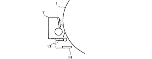
【図19】本発明の他の実施形態の要部構成図
【図20】光学センサの特性図
【図21】カブリ電位差を制御する動作を示す制御フローチャート
【図22】プロセスシーケンスEの電位変化を示すタイミングチャート
【図23】プロセスシーケンスEの全体のタイミングチャート
【図24】プロセスシーケンスDの電位変化を示すタイミングチャート
【図25】プロセスシーケンスDの全体のタイミングチャート
【図26】カブリ電位差に対する感光体キャリア付着量を示す図
【図27】プロセスシーケンスEの変形例を示すタイミングチャート
【図28】本発明の更に他の実施形態の一部構成図
【図29】従来の画像形成装置の要部構成図
【図30】従来の画像形成装置における電位変化を示すタイミングチャート
【図31】カブリ電位差に対する帯電不良トナーの付着量を示す図
【図32】環境変化に対する帯電不良トナーの分布変化を示す図[0001]
TECHNICAL FIELD OF THE INVENTION
The present invention relates to an image forming apparatus such as an electrophotographic copying machine, a printer, and a facsimile machine, and more particularly, to maintain good image quality by selectively forcibly discharging poorly charged toner in a developing device to the outside of the developing device. The present invention relates to an image forming apparatus that can be designed.
[0002]
[Prior art]
An image forming apparatus using an electrophotographic method generally includes, as shown in FIG. 29, a
[0003]
When the
[0004]
In the transfer step in the series of image forming steps, not all of the toner forming the toner image on the surface of the
[0005]
Therefore, a cleaning device including a
[0006]
The toner removed from the surface of the photoreceptor by the cleaning unit is collected by a toner remover. Discarding all of the collected toner increases waste of toner. In recent years, in order to reduce waste of toner and make effective use of the toner, the toner collected in the toner remover is transported to a developing device. Various image forming apparatuses having a toner recycling mechanism for reuse after reuse have been proposed. In FIG. 29, the toner recycling mechanism includes a
[0007]
Next, control of the fog potential difference in the image forming apparatus having the above configuration will be described with reference to FIG. FIG. 2 shows a timing chart of the photosensitive member surface potential and the developing bias voltage in a so-called single mode in which copying is performed on one transfer material. The fog potential difference is represented by a potential difference between a surface potential of the photoconductor and a bias voltage (development bias voltage) applied to the developer carrier. This fog potential difference is set to an appropriate value so that the toner does not unnecessarily adhere to the photoconductor. In the example shown in FIG. 30, the toner is a negatively charged body, and the higher the developing potential indicated by reference numeral V1 (approaching to the + side), the larger the toner adhesion amount, while the excess toner has a negative potential. The higher (closer to the + side) the more difficult it is to adhere. The area indicated by the hatched portion in the drawing is a portion exposed by the laser, and the toner adheres to the hatched portion and is developed.
[0008]
However, the toner that is correctly controlled as shown in FIG. 30 is a normal toner that is negatively charged by stirring, and a reversely charged toner that is positively charged and an uncharged toner that is not charged are poorly adsorbed to the photoconductor. Or undesired adhesion. FIG. 31 is a diagram showing the amount of the photoreceptor adhered to the oppositely charged toner (+ charged toner), the uncharged toner and the carrier with respect to the fog potential difference. From this figure, the most desirable characteristic when the fog potential difference is -150 V, that is, It can be seen that the adhesion of the charged toner and the oppositely charged toner can be minimized. It can also be seen that there is no problem with an undesired carrier attached to the photosensitive member if the fog potential difference is in the range of 0 to 250 V. Thus, in the example shown in FIG. 30, the fog potential difference is maintained at -150 V to control the photoconductor surface potential and the developing bias voltage. That is, the surface potential V of the photoconductor, which has a high potential on the negative side, 0 From the start (timing a) of the surface potential V 0 Rises to -150 V (timing b), application of the developing bias voltage Vb is started while maintaining the fog potential difference of -150 V, and V 0 = −550 V and Vb = −400 V (timing c), and after a predetermined time elapses, an image area is formed. In the image area, the photoconductor is irradiated with the developed image, and the portion to which the toner is to be adhered is developed potential V1 (−). 100 V), and when the image area ends, the surface potential V of the photoconductor is maintained while maintaining the fog potential difference. 0 And the bias voltage Vb rises until both become the 0 level (timing e, f).
[0009]
[Problems to be solved by the invention]
However, the toner recycling section requires a large-scale and mechanically complicated toner conveying member such as a screw conveyor, and has a drawback that the number of components and the size of the apparatus cannot be avoided. Even if the control is performed at the timing shown in the above, the fog potential difference of the oppositely charged toner (+ charged toner) and the uncharged toner does not become 0 even if the fog potential difference is set to the optimal value of -150 V, so that it adheres to the photosensitive member surface. There is a problem of doing. In particular, as shown in FIG. 32, when the image formation progresses or the environment in which the developer is used such as high temperature and high humidity changes, the ratio of the oppositely charged toner and the uncharged toner to the whole increases relatively, and as a result, There was a problem that the image quality deteriorated more and more.
[0010]
Further, the toner recycled in the toner recycling unit is generally inferior in various characteristics to the toner originally in the developing tank of the developing device because the toner is stressed by repeated use. For this reason, when the recycled toner is recirculated, the above problem becomes more remarkable. When the proportion of the oppositely charged toner or the uncharged toner in the developing tank increases, the developing is performed even though the amount of the toner is sufficient. The magnetic permeability sensor cannot accurately detect the normal toner concentration in the developer, and new toner is replenished more than necessary from the toner hopper, increasing the image density, or conversely, the amount of new toner replenished is insufficient. There has been a problem that the image density is reduced.
[0011]
Japanese Patent Application Laid-Open No. 7-319356 discloses a recycling unit for re-transporting toner collected by a metal roller to a developing device. Japanese Patent Application Laid-Open No. 9-311541 discloses a method in which black toner is solidly charged when toner is excessively charged. Although a configuration is shown in which the charged toner is removed by forming an image, the removal of uncharged toner or oppositely charged toner is not disclosed. In Japanese Patent Application Laid-Open No. Hei 6-130810, a residual toner storage unit for storing residual toner collected from a photoconductor and a new toner storage unit are provided so that toner can be reused without using a large-scale toner recycling unit. However, this publication does not disclose removal of uncharged toner or oppositely charged toner.
[0012]
A first object of the present invention is to make it possible to easily remove uncharged toner remaining on the surface of a photoreceptor and poorly charged toner such as reversely charged toner.
[0013]
Another object of the present invention is to provide an image forming apparatus capable of removing poorly charged toner without affecting the rotation of the photoconductor and the image forming process.
[0014]
Still another object of the present invention is to provide an image forming apparatus capable of removing and discarding an oppositely charged toner that is difficult to reuse, and reusing an uncharged toner as a recycled toner.
[0015]
Still another object of the present invention is to provide an image forming apparatus capable of removing only the amount of defectively charged toner on the surface of a photoreceptor is equal to or more than a predetermined amount.
[0016]
[Means for Solving the Problems]
The present invention is configured as follows in order to solve the above problems.
[0017]
(1) In an image forming apparatus for supplying toner by a developing device to an electrostatic latent image formed on a photoreceptor surface by an electrophotographic method and visualizing the electrostatic latent image,
During the non-image forming period during the pre-rotation or post-rotation of the photoconductor, the fogging potential difference represented by the potential difference between the surface potential of the photoconductor and the bias voltage to the developer carrier is variably controlled to expose poorly charged toner. A control unit for forcibly attaching to the body,
Cleaning means for removing poorly charged toner from the surface of the photoreceptor which is provided so as to be capable of contacting and separating from the surface of the photoreceptor, and
Characterized by the provision of
As shown in FIG. 31, since the fog potential difference and the amount of adhesion of poorly charged toner (uncharged toner or oppositely charged toner) to the photoconductor have a certain relationship, by controlling the fog potential difference, This is forcibly adhering to the photoconductor and cleaning it. In this case, the control of the fog potential difference is performed during the non-image forming period at the time of the pre-rotation or post-rotation of the photoconductor. As a result, defectively charged toner can be removed without affecting the image forming process. Further, since the cleaning means for removing the poorly charged toner is provided so as to be able to contact and separate from the surface of the photoreceptor, the cleaning means is brought into contact with the surface of the photoreceptor only when necessary to remove the poorly charged toner. By doing so, abrasion of the surface of the photoconductor is prevented as much as possible, and even if the rotation period of the photoconductor is caused by adjusting the contact period to the non-image forming period, the image forming process is not affected.
[0018]
(2) the cleaning means for removing the poorly charged toner downstream And a communication unit with a developing device, and a cleaning unit for collecting uncharged toner that removes and recovers uncharged defective toner in the poorly charged toner from the photoreceptor surface when the cleaning unit is separated,
The cleaning means for removing the poorly charged toner removes the oppositely charged toner in the poorly charged toner at the time of contact.
[0019]
Of the uncharged toner, the uncharged toner is recovered, returned to the developing device, and re-stirred to be converted into a toner having a normal charging characteristic. The utilization efficiency of the toner can be improved. On the other hand, since the oppositely charged toner is removed and discarded, most of the developing device is eventually occupied by toner having normal charging characteristics, so that a copy having good image quality without fog can be stably obtained. Can be obtained.
[0020]
Further, since the transport of the recycled toner (uncharged toner) to the developing device is performed by the photoconductor, a large-scale toner recycling system (such as a screw conveyor) is not required. For this reason, the transport of the recycled toner can be efficiently performed in the shortest route while eliminating the extra stress applied to the toner.
[0021]
In the configuration of the present invention, when the cleaning means for removing the poorly charged toner is in contact with the surface of the photoreceptor, the untransferred toner, the oppositely charged toner and the foreign matter adhering to the photoreceptor are selectively removed by the cleaning means. When the cleaning unit is separated from the surface of the photoreceptor, only the uncharged toner adhering on the photoreceptor is selectively removed and recovered by the uncharged toner recovery cleaning unit.
[0022]
(3) The control unit performs the following controls (3-1) and (3-2).
[0023]
(3-1) When the power supply to the main charging device is started at the time of the pre-rotation, the photosensitive member is transferred to the developer carrier with a delay longer than the time required for the photosensitive member to advance from the charging process facing position to the developing process facing position. , And the oppositely charged toner and the uncharged toner are forcibly attached to the photoreceptor in this order.
[0024]
(3-2) When the power supply to the main charging device is stopped during the post-rotation, the photosensitive member is transferred to the developer carrier with a delay longer than the time required for the photosensitive member to advance from the charging process facing position to the developing process facing position. Is stopped, and the uncharged toner and the oppositely charged toner are forcibly adhered to the photoreceptor in this order.
[0025]
When the start of copying is instructed, there is a pre-rotation cycle first, followed by an image forming cycle, and finally a post-rotation cycle. In the present invention, the poorly charged toner is forcibly adhered to the photoreceptor at the time of the pre-rotation, and is also forcibly adhered to the photoreceptor at the time of the rotation after the image formation period. Of these poorly charged toners adhering to the photoreceptor, those of the oppositely charged toner are removed by the cleaning means for removing the oppositely charged toner, and those of the uncharged toner are removed and collected by the cleaning means for collecting the uncharged toner. Is done.
[0026]
As described above, the charge-defective toner is removed before and after image formation, and the reusable uncharged toner is collected, converted into a toner having normal charge characteristics, and then reused. The two types of poorly charged toner, which are different from each other, can be reliably removed, and most of the uncharged toner can be collected in the developing device. For this reason, it is possible to stably obtain a good copy with good toner use efficiency and no fog.
[0027]
(4) The fog potential difference at the time of removing the oppositely charged toner is set to a potential difference that is larger than the fog potential difference set for normal toner adhesion and does not induce carrier adhesion, and the uncharged toner is removed. The fog potential difference at the time of collection is set to a potential difference that is smaller than the fog potential difference set for regular toner adhesion and does not induce regular toner adhesion.
[0028]
As is apparent from FIG. 31, when the fog potential difference is larger than +250 V in the + potential direction, carrier adhesion to the photoreceptor hardly causes a problem. Therefore, assuming that the fog potential difference during image formation is $ 150 V, by controlling this fog potential difference to $ 250 V, the oppositely charged toner (+ charged toner) is transferred onto the photoreceptor in a state where the carrier does not adhere to the photoreceptor. Can be forcibly adhered to. The fog potential difference that does not induce the carrier adhesion according to the present invention means a potential difference of about 250 V in the example shown in FIG.
[0029]
Further, as the fog potential difference approaches 0 V, the amount of uncharged toner adhered to the photoconductor increases, but as the fog potential difference approaches or exceeds 0 V, the photoconductor surface potential and the developing bias voltage are reversed. Therefore, the fog potential difference is set so that only the uncharged toner adheres to the photoconductor.
[0030]
As a result, two types of poorly charged toner having different charging characteristics can be removed together, and the uncharged toner is recovered by the cleaning means for recovering the uncharged toner. Therefore, even if the operation immediately proceeds to the image forming operation, a good copy without fog can be stably obtained.
[0031]
(5) The control unit removes either the uncharged toner or the oppositely charged toner in each of the first half period and the second half period between the sheets in each image forming period when forming a plurality of continuous images, and The fog potential difference is controlled so that both toners are removed during the period.
[0032]
When image formation is performed continuously on a plurality of sheets, the potential difference between the surface potential of the photoconductor and the developing bias voltage between sheets is conventionally set to the same value as in a normal image forming period. However, by using the sheet interval to control switching of the fog potential difference between the first half period and the second half period, defectively charged toner having different charging characteristics can be forcibly adhered onto the photoconductor in each period. . Therefore, in performing continuous copying, it is not necessary to provide a period for discharging the poorly charged toner in order to maintain the image quality, so that good image quality can be obtained without particularly lowering the utilization efficiency of the machine and the speed of image formation. Can be maintained.
[0033]
(6) The cleaning means for removing the poorly charged toner is switched in accordance with the attached matter on the surface of the photoreceptor.
[0034]
By keeping the cleaning means for removing poorly charged toner out of contact with the photoreceptor unless it is necessary, unnecessary consumption of the collection / removal member, damage to the photoreceptor, and exposure to light due to contact with the collection / removal member The rotational resistance of the body is suppressed.
[0035]
(7) The contact force of the uncharged toner collecting cleaning means to the photoreceptor is set smaller than the contact force of the poorly charged toner removing cleaning means.
[0036]
By relatively reducing the contact force of the uncharged toner collecting cleaning means to the photoreceptor, unnecessary cleaning of the uncharged toner which is removed and collected by the cleaning means, returned to the developing device and reused, is performed. Stress is reduced.
[0037]
(8) In the above (1), a cleaning means for recovering and recycling the recycled toner, which is provided with a means for removing and recovering the untransferred toner remaining on the surface of the photoreceptor from the photoreceptor and conveying it as a recycled toner to the developing device, It is characterized by having.
[0038]
In the present invention, the untransferred toner remaining on the surface of the photoreceptor after transfer is removed and collected by a cleaning blade or the like, and a transporting unit such as a screw conveyor for transporting the unremoved toner to the developing device as a recycled toner is provided. According to the cleaning device, the remaining untransferred toner can be reused as recycled toner as in the conventional copying apparatus, and the uncharged toner or the oppositely charged toner can be reused by the recycled toner collecting cleaning device. In this way, most of the toner in the developing device is occupied by toner exhibiting normal charging characteristics, and it is possible to stably obtain a copy having good image quality without fogging. it can.
[0039]
(9) In the above (8), the control section variably controls the fog potential difference during the pre-rotation,
The cleaning means for removing poorly charged toner is brought into contact with the surface of the photoreceptor when the photoreceptor is stopped, and is separated before the image formation which prevails after the charging step facing position passes through the cleaning means.
[0040]
Even if rotation unevenness occurs due to the rotational load of the photoconductor when the cleaning unit for removing the poorly charged toner contacts the surface of the photoconductor, the contact operation is released before the image formation, and the cleaning unit performs image formation. In some cases, the copy is separated from the photoreceptor surface, so that a good copy of the image can be stabilized without affecting the image and without impairing the copy efficiency.
[0041]
(10) In the above (8), the cleaning means for removing defectively charged toner is separated after the photosensitive member is stopped after the image formation, and waits in a separated state until the next rotation of the photosensitive member.
[0042]
Since the cleaning means for removing poorly charged toner waits in a separated state until the next rotation of the photoconductor, it can prevent permanent deformation of the cleaning blade, thereby expecting stable cleaning characteristics for a long time. Can be.
[0043]
(11) The cleaning means for removing the poorly charged toner and the cleaning means for collecting the recycled toner each have a cleaning blade, and the blade hardness of the cleaning means for removing the poorly charged toner is determined by the blade of the cleaning means for collecting the recycled toner. It is characterized by being set lower than the hardness.
[0044]
Generally, the cleaning blade of the cleaning means for collecting the recycled toner is always in contact with the surface of the photoreceptor, but the hardness of the cleaning blade of the cleaning means for removing the toner for defective charging is made lower than the hardness of the cleaning blade. As a result, mechanical stress on the photoconductor can be reduced, and thereby stable toner removal can be performed without damaging the film quality.
[0045]
(12) The amount of biting of the cleaning blade of the cleaning means for removing defectively charged toner into the photoreceptor is set smaller than the amount of biting of the cleaning blade of the cleaning means for collecting recycled toner.
[0046]
As in (11) above, by reducing the mechanical stress on the photoreceptor, it is possible to perform stable toner removal without damaging the film quality.
[0047]
(13) The amount of protrusion of the cleaning blade of the cleaning means for removing defectively charged toner is set to be smaller than the amount of protrusion of the cleaning blade of the cleaning means for collecting recycled toner.
[0048]
In the present invention, similarly to (11) and (12), the mechanical stress on the photoconductor is reduced. Further, it is possible to prevent the blade reversal phenomenon at the time of switching the contact operation of the cleaning blade of the cleaning means for removing the poorly charged toner.
[0049]
(14) The cleaning means for removing the poorly charged toner is controlled so that the contact start portion of the poorly charged toner that has been forcibly adhered to the photoreceptor starts contacting.
[0050]
It is possible to prevent the blade reversal phenomenon at the time of switching the contact operation of the cleaning blade of the cleaning means for removing the poorly charged toner.
[0051]
(15) The cleaning blade for removing the defectively charged toner has a total length shorter than that of the cleaning blade for collecting the recycled toner.
[0052]
The toner passing through the blade end of the cleaning means for removing defectively charged toner, which is generated when the separation and contact with the photoreceptor are repeated, can be reliably collected by the cleaning blade of the cleaning means for collecting the recycled toner. It is possible to prevent contamination beforehand.
[0053]
(16) In the above (1), there is provided an optical sensor for detecting poorly charged toner on the surface of the photoreceptor, and the control unit performs variable control of the fog potential difference based on the detection result of the optical sensor. I do.
[0054]
The present invention uses an optical sensor to variably control the fog potential difference only when necessary to remove poorly charged toner. As a result, it is possible to stably obtain a copy having good image quality without fogging without greatly reducing the use efficiency of the machine and the speed of image formation.
[0055]
(17) The optical sensor detects a poorly charged toner only when the cumulative number of image formations becomes equal to or greater than a set value.
[0056]
When the cumulative number of copies is small, the distribution of the poorly charged toner with respect to the entirety does not increase so much as shown in FIG. Therefore, only when the cumulative number of copies exceeds a set value, the optical sensor detects whether or not the defectively charged toner is equal to or more than a predetermined value. This makes it possible to forcibly remove the poorly charged toner that is not suitable as the recycled toner without impairing the utilization efficiency of the machine.
[0057]
(18) The optical sensor detects a poorly charged toner only when the accumulated operating time of the developing device has exceeded a set value.
[0058]
Similarly, by performing the detection of the poorly charged toner only when the cumulative operating time of the developing device is equal to or longer than the set time, it is possible to forcibly remove the poorly charged toner at a stable timing regardless of the frequency of use of the copying apparatus. It becomes possible.
[0059]
(19) The optical sensor performs a detection operation at the time of non-image formation and at the time of pre-rotation or post-rotation, and the control unit performs variable control of a fog potential difference based on a detection result of the sensor, and The cleaning means for removing poorly charged toner performs control of contact and separation with the surface of the photoreceptor based on the detection result of the sensor.
[0060]
By performing the above detection operation at the time of pre-rotation or post-rotation at the time of non-image formation, the use efficiency of the machine is not deteriorated and the speed of image formation is not particularly reduced.
[0061]
(20) After transferring the visualized image on the surface of the photoreceptor onto paper, a peeling charger is provided for peeling off the transferred image.
The control unit controls the voltage of the peeling charger to cancel the residual potential on the surface of the photoconductor when the cleaning unit for removing the poorly charged toner is in contact with the photoconductor.
[0062]
By canceling the residual potential on the surface of the photoreceptor before removing the poorly charged toner, the poorly charged toner can be easily removed, and the inside of the apparatus due to the poorly charged toner can be prevented.
[0063]
(21) a static elimination lamp that is disposed immediately before the charging process position and cancels a residual potential on the surface of the photoconductor;
When the cleaning means for removing defectively charged toner is in contact with the photoreceptor, the control unit controls the amount of light of the discharge lamp to cancel the residual potential on the surface of the photoreceptor.
[0064]
Similarly to the above (20), it is possible to easily remove the poorly charged toner adhered to the photoreceptor, and also to prevent the inside of the apparatus due to the poorly charged toner from occurring.
[0065]
(22) The light amount of the discharging lamp is set to be lower than the light amount of the discharging lamp used in the copying process.
[0066]
As described above, by setting the light amount of the static elimination lamp to be darker than usual, it is possible to easily remove the poorly charged toner deposited on the photoconductor without giving excessive photo fatigue to the photoconductor. At the same time, it is possible to prevent in-machine contamination due to poor charging toner.
[0067]
(23) The control unit sets the fog potential difference to be smaller than the fog potential difference at the time of image formation when removing uncharged toner in the poorly charged toner, and sets the fog potential difference at the time of image formation when removing the oppositely charged toner in the poorly charged toner. The fog potential difference is set to be larger than the fog potential difference.
[0068]
By forcibly removing both the uncharged toner and the oppositely charged toner that are not suitable as the recycle toner, the developing device is mostly occupied by the toner exhibiting the normal charging characteristics, thereby providing a good fog-free toner. A copy having high image quality can be stably obtained.
[0069]
(24) The controller is characterized in that the fog potential difference is variably controlled to a different value depending on the surrounding environment.
[0070]
Since the fog potential difference characteristic shown in FIG. 31 varies depending on the surrounding environment such as humidity and temperature, according to the present invention, only the poorly charged toner can be appropriately adhered to the photoreceptor regardless of the surrounding environment conditions. This makes it possible to prevent carrier adhesion and in-machine contamination.
[0071]
(25) The control section performs variable control of the fog potential difference by setting the surface potential of the photoconductor to be equal to or lower than the surface potential at the time of image formation.
[0072]
By appropriately adhering only the poorly charged toner on the photoreceptor at a low potential, the toner adhering on the photoreceptor can be easily removed, and carrier adhesion and contamination in the apparatus can be prevented. .
[0073]
(26) The controller performs variable control of the fog potential difference by controlling the surface potential of the photoconductor in accordance with the frequency of use of the image forming apparatus main body.
[0074]
By determining the charging potential of the photoconductor in accordance with the frequency of use of the radiating device, that is, the charging level of the developer, it is possible to prevent carrier adhesion and contamination inside the machine regardless of the state of the developer when removing poorly charged toner. it can.
[0075]
(27) The control unit variably controls the fog potential difference by controlling the surface potential of the photoconductor and the bias voltage to the developer carrier by pulse width modulation.
[0076]
Since the potentials of the photosensitive member and the developer carrier, which are capacitive loads, are proportional to the time for supplying a predetermined current, a desired potential can be easily obtained by pulse width modulation for controlling the current supply time. it can. The surface potential of the photoconductor is the same as the voltage applied to the grid facing the photoconductor, and the potential of the developer carrier is also the same as the developing bias voltage. In order to reach the target value while maintaining a constant gradient for both the developing bias voltage and the photoconductor surface potential, simple on-off control instantaneously reaches and changes vertically, which is difficult to control. In the pulse width modulation, since the potential can be changed with the passage of time, the control of the power supply device is performed with high accuracy and efficiency, leading to an improvement in the performance of the image forming apparatus.
[0077]
BEST MODE FOR CARRYING OUT THE INVENTION
Hereinafter, embodiments of the present invention will be described.
[0078]
[First Embodiment]
FIG. 1 is a schematic configuration diagram of an image forming unit in the image forming apparatus according to the first embodiment of the present invention.
[0079]
As shown in FIG. 1, the image forming apparatus includes a
[0080]
The image forming apparatus has a first cleaning device (cleaning device for removing defectively charged toner) 7 and a second cleaning device (cleaning device for collecting uncharged toner) 8 as cleaning means. The
[0081]
In the above-described image forming apparatus, the uncharged toner or the oppositely charged toner existing in the developing
[0082]
Further, the residual toner (untransferred toner) generated in the transfer process contains impurities such as paper dust and talc, and it is inconvenient to return the residual toner to the developing
[0083]
Next, a description will be given of a configuration for selectively adhering the poorly charged toner composed of the uncharged toner or the oppositely charged toner to the photosensitive member by adjusting the bias voltage and forcibly discharging the toner out of the developing device.
[0084]
FIG. 2 is a timing chart for explaining an image forming operation of the image forming apparatus. In the present embodiment, as shown in FIG. 31, the toner has a charging characteristic in which the fog potential difference is -150 V and the adhesion of the uncharged toner and the + charged toner is minimized, and the fog potential difference in the image area is as shown in FIG. It is assumed that the voltage is set to -150V. Also, the surface potential V of the photoconductor in the image area 0 Is -550V, and the developing bias voltage Vb to the developing
[0085]
In FIG. 2, when the copying operation starts, the pre-rotation of the developing
[0086]
Thereafter, the fog potential difference of -20 V is maintained until the bias voltage Vb reaches a predetermined voltage of -400 V (timing D), during which time the uncharged toner adheres to the photoconductor, as is apparent from FIG. Will do.
[0087]
Photoconductor surface potential V 0 Reaches −550 V (timing I), an image area is formed, during which exposure of the original image is performed. When the image formation is completed, the
[0088]
Photoconductor surface potential V 0 Reaches −250 V (timing G), the bias voltage Vb is sharply dropped until it reaches 0 (timing H), and the surface potential V 0 In the period from timing G to timing J until timing becomes 0 (timing J), the + charged toner adheres to the photoconductor similarly to the timing A to timing C.
[0089]
Note that V between timings C to D and F to G 0 −Vb = −20 V, which is determined by considering the use conditions of the photoreceptor, that is, the number of prints, the temperature and the humidity, and the like. 0 The fog potential difference of −20 V is appropriately changed depending on the use condition of the photoconductor.
[0090]
In this way, after issuing a copy command for one transfer material, during the pre-rotation, the positively charged toner is forcibly adhered to the photosensitive member during the period up to timing C, and from time C to timing D During the period, the uncharged toner is forcibly attached to the photoconductor. When the image formation is completed and the post-rotation is started, the uncharged toner is forcibly attached to the photoconductor during a period from timing G to the time, and the positively charged toner is forcibly adhered to the photoconductor during a period from timing G to timing J. Let it. Note that the addition time of T1 and T2 is longer than the time required for the charging device facing position (photosensitive member position facing the charging device 2) to advance to the developing device facing position (photosensitive member position facing the developing
[0091]
On the other hand, control of contact and separation of the
[0092]
The
[0093]
3 and 4 are partial configuration diagrams of the
[0094]
The
[0095]
5 and 6 show fog potential difference characteristics under a high humidity environment and a low humidity environment among the usage conditions of the photoconductor. As described above, the adhesion amount of the uncharged toner and the oppositely charged toner with respect to the fog potential difference fluctuates due to the influence of humidity. Fine adjustment of the fog potential difference can be performed in consideration of this variation. Specifically, a humidity sensor is provided, and control such as correction of the developing bias voltage Vb is performed based on the sensor output.
[0096]
Next, a circuit configuration for performing variable control of the fog potential difference in the control unit will be described with reference to FIGS.
[0097]
FIG. 7 shows a circuit configuration for controlling the surface potential of the photoconductor, that is, the potential applied to the grid of the
[0098]
In the above configuration, in order to reach the predetermined potential −550 V while maintaining the surface potential of the
[0099]
As described above, in the present embodiment, the developing bias voltage Vb and the photoconductor surface potential V 0 In both cases, pulse width modulation (PWM modulation) is performed. However, if this is simply turned on and off, the target potential is instantaneously reached, and the potential change becomes a vertical change, making voltage control difficult. On the other hand, in the case of the PWM control, it is easy to change the potential in a proportional relationship while maintaining a constant slope with the passage of time, so that the output control of the power supply device can be performed with high accuracy and efficiency. This leads to an improvement in the performance of the image forming apparatus.
[0100]
As described above, the poorly charged toner is caused to adhere to the
[0101]
[Second embodiment]
In the second embodiment of the present invention, when forming a plurality of continuous images, the fog potential difference is controlled during each image forming period.
[0102]
FIG. 10 shows a timing chart for controlling the fog potential difference. The timings A to F in the same drawing are timings similar to the timings A to F in FIG.
[0103]
In a mode in which a plurality of sheets are continuously formed, that is, in a multi mode, the surface potential V 0 Is maintained at the above-mentioned constant value of -550V. On the other hand, the developing bias voltage Vb is kept constant at -400 V in a conventional apparatus, but is changed in the range of -530 V to -300 V in this embodiment. That is, the sheet interval in each image forming period is divided into a first half period and a second half period. In the first half period, the developing bias voltage Vb is changed from −400 V to −530 V between timings A and B, and this state is changed to timing B− It is held between timings C. In the latter half period, the developing bias voltage Vb is changed from −530 V to −300 V between the timing C and the timing D, and this state is maintained between the timing D and the timing E, and the timing E− immediately before the next image area is changed. At timing F, the developing bias voltage Vb is returned to -400V. By such control, the uncharged toner is removed during the timing B-timing C of the first half period between copy sheets, and the oppositely charged toner is removed during the timing D-timing E of the second half period. Note that the
[0104]
[Third embodiment]
In the third embodiment of the present invention, similarly to the second embodiment, when performing continuous image formation on a plurality of sheets, the fog potential difference is controlled in each image forming period. FIG. 11 shows a timing chart for controlling the fog potential difference. The difference from the timing chart shown in FIG. 10 is that the developing bias voltage Vb is increased from −400 V to −300 V in the first half period between copy sheets to remove the oppositely charged toner, and is reduced to −530 V in the second half period. The point is that uncharged toner is removed. In the third embodiment shown in FIG. 10, the
[0105]
The contact force of the
[0106]
As for the
[0107]
[Fourth embodiment]
FIG. 12 shows a fourth embodiment of the present invention.
[0108]
The difference from the conventional configuration shown in FIG. 29 is that, in this embodiment, the photosensitive unreacted toner remaining on the
[0109]
Next, a control flow for removing the poorly charged toner in this embodiment will be described with reference to FIGS.
[0110]
FIG. 14 shows a control flow for removing poorly charged toner.
[0111]
When a copy start command is issued, first, a reference is made to the cumulative movable time αt to determine whether or not the time is equal to or longer than a preset time (for example, 3600 seconds). As shown in FIG. 15, the rise and fall of the photosensitive member surface potential and the developing bias voltage are performed with a normal fog potential difference. In FIG. 14, this control is performed by employing the process sequence A.
[0112]
・ Process sequence A
In this sequence, the photoconductor surface potential V 0 In addition, when the developing bias voltage Vb rises, the uncharged toner is removed. That is, the
[0113]
・ Process sequence B
This is executed when the cumulative movable time is equal to or longer than αt. In the process sequence B, the control of the photosensitive member surface potential and the developing bias voltage is performed as shown in FIG.
[0114]
First, in ST10 to ST14, the same control as in ST2 to ST6 is performed to remove the adhesion of the uncharged toner that has adhered to the uncharged portion of the photoconductor immediately after startup.
[0115]
Subsequently, when the image forming process is completed, the developing bias voltage Vb is switched from -450V to -300V. Thereby, the fog potential difference is set to -300V. When the fog potential difference is −300 V, as shown in FIG. 31, the oppositely charged toner (+ charged toner) moves to the
[0116]
According to the above procedure, as shown in FIG. 16, the reversely charged toner is removed at the time TA during the post rotation of the photoconductor, and the uncharged toner is removed at the time TB. The poorly-charged toner removed in this way is transported to a collection container (not shown) by the transporting
[0117]
After the
-Set the blade protrusion amount (see Fig. 3) to 8mm or less
・ Blade penetration is set to 1mm or less
-Set the rubber hardness of the blade to 60 degrees or less
By doing so, it was found that the photosensitive film of the
[0118]
Further, with the contact / separation operation of the
・ L1 development effective area
・
・ L3 Effective area of
By doing so, even when the
[0119]
In the image forming apparatus in which the driving sources are individually arranged in the paper feeding system, the process system, and the conveyance / fixing system as in the above-described embodiment, the poorly charged toner is removed immediately after the development process of the final image area is completed. This makes it possible to remove the poorly charged toner without impairing the copying efficiency, but at least in an image forming apparatus in which the photoconductor and the fixing device are driven by the same drive source. In other words, a change in load on the
[0120]
Note that also in the fourth embodiment, the photoconductor surface potential V 0 The control of the developing bias voltage Vb is performed by a pulse width modulation method as shown in FIG.
[0121]
[Fifth Embodiment]
FIG. 19 shows a fifth embodiment of the present invention. The difference from the fourth embodiment shown in FIG. 12 is that an
[0122]
The
[0123]
Hereinafter, the fog potential difference control operation of the image forming apparatus of this embodiment will be described with reference to FIG.
[0124]
First, in ST30, the result of the detection of the poorly charged toner by the
[0125]
・ Process sequence E
The timing chart of the process sequence E is as shown in FIG. In this process sequence E, the photoconductor surface potential V o The rise of the developing bias voltage Vb is the same as in the conventional case shown in FIG. 30, and the fog operation is performed while maintaining the fog potential difference of -150 V to shift to the image forming process.
[0126]
When image formation is completed in ST40 of FIG. 21, the
[0127]
By the above processing, the oppositely charged toner (+ charged toner) is removed from the
[0128]
In ST30 of FIG. 21, if the previous result is the flag ON, first, the accumulated operation time αt up to this time is determined (ST31). Although the cumulative operation time αt is determined here, any value may be used as long as it is a value that correlates to the use state (continuous use period) of the image forming apparatus, such as the cumulative number of copies. If the accumulated operation time αt is less than a preset time (here, 3600 seconds), the process sequence C is adopted. Although the operation for the process sequence C is not shown here, the same sequence operation as the process sequence A shown in FIG. 15 of the fourth embodiment is performed.
[0129]
If the cumulative operation time αt is equal to or longer than the set time, the process sequence D is adopted. For the process sequence D, the operations after ST32 are performed. FIG. 24 is a timing chart showing a change in the potential, and FIG. 25 is an overall timing chart.
[0130]
・ Process sequence D
After the drive system operates, the photosensitive member surface potential V o Is linearly raised to -650 V, while the developing bias voltage Vb is not output during the time t1. That is, until the time t1 elapses, the fog potential difference changes from 0V to minus 350V. Thereby, as shown in FIG. 31, the uncharged toner and the oppositely charged toner (+ charged toner) move to the
[0131]
The poorly charged toner transferred as described above is detected at timings t1 ′ and t2 ′, which reach the
[0132]
In FIG. 21, the photoconductor surface potential V o Is started in ST50, and at the time of controlling the fog potential difference, detection by the
[0133]
The reading timings t1 ', t2', t3 ', and t4' of the
[0134]
[Sixth embodiment]
In the fifth embodiment in which the poorly charged toner is forcibly adhered onto the
[0135]
That is, as shown in FIG. 5 and FIG. 6, from the characteristics of poorly charged toner and carrier adherence to the fog potential difference in a high humidity environment (at a humidity of 80%) and similar characteristics in a low humidity environment (at a humidity of 20%), When the method of controlling the fog potential setting from 0 V to -350 V as in the fifth embodiment, excessive adhesion may be caused in a high humidity environment, and carrier adhesion may be caused in a low humidity environment. Therefore, in order to prevent this, the surrounding environmental condition is detected, and the poorly charged toner is detected by the optical sensor according to the environmental condition at that time. It is desirable that the fog potential setting is appropriately determined so as to cause forcible adhesion. That is, it is desirable to separately provide a humidity sensor and control the fog potential difference based on the detection result. FIG. 26 is a diagram showing the adhesion of the carrier to the photoconductor with respect to the fog
[0136]
[Other embodiments]
In order to efficiently collect the forcibly adhered toner, it is desirable to cancel the electric charge on the
[0137]
Since the provision of the above-mentioned
[0138]
The photoconductor surface potential V o The above control of the developing bias voltage Vb is performed by the pulse width modulation circuit shown in FIG. 7 as in the other embodiments.
[0139]
【The invention's effect】
According to the present invention, the following effects can be obtained.
[0140]
(1) Forcibly adhering a reversely charged toner or an uncharged toner to the photoreceptor by variably controlling the fog potential difference represented by the potential difference between the surface potential of the photoreceptor and the bias voltage to the developer carrier. By selectively removing the toner by the cleaning means for removing defectively charged toner, a good copy without fog can be stably obtained.
[0141]
(2) The uncharged toner is reused by removing the oppositely charged toner by the defectively charged toner removing cleaning unit and removing and collecting the uncharged toner by the uncharged toner recovery cleaning unit disposed on the downstream side. And the toner use efficiency is improved. In this case, most of the developing device without the oppositely charged toner is occupied by the toner having the normal charging characteristics, so that a copy having good image quality without fog can be stably obtained. Further, since the uncharged toner is transported by the photoconductor itself, a conventional large-scale toner recycling system (consisting of a screw conveyor or the like) is not required. The transport can be performed efficiently with the shortest route.
[0142]
(3) By using the pre-rotation time and the post-rotation time, the poorly charged toner is forcibly adhered to the photoreceptor, and the toner is cleaned. No good copy can be stably obtained.
[0143]
(4) Even in the multi-mode in which continuous image formation is performed on a plurality of sheets, good image quality can be maintained without particularly lowering the utilization efficiency of the machine and the image formation speed.
[0144]
(5) By controlling the fogging potential difference by the pulse width modulation circuit, a desired potential can be easily reached, and voltage control can be performed with high accuracy and efficiency.
[Brief description of the drawings]
FIG. 1 is a configuration diagram of a main part of a first embodiment of the present invention.
FIG. 2 is a timing chart showing a potential change during fog potential difference control.
FIG. 3 is a partial configuration diagram of a first cleaning device (at the time of contact).
FIG. 4 is a partial configuration diagram of the cleaning device (at the time of separation).
FIG. 5 is a diagram illustrating characteristics of toner and carrier adhesion amounts with respect to a fog potential difference in a high humidity environment.
FIG. 6 is a diagram illustrating characteristics of toner and carrier adhesion amounts with respect to fog potential difference in a low humidity environment.
FIG. 7 illustrates a pulse width modulation circuit.
FIG. 8 is a diagram showing a change in photoconductor surface potential with respect to a grid applied voltage by a pulse width modulation circuit.
FIG. 9 is a diagram illustrating a change in a developing bias voltage with respect to a duty in the pulse width modulation circuit.
FIG. 10 is a timing chart showing a potential change in a multi mode.
FIG. 11 is a timing chart showing a potential change in the multi mode.
FIG. 12 is a configuration diagram of a main part of another embodiment of the present invention.
FIG. 13 shows a drive system.
FIG. 14 is a diagram showing a control flowchart.
FIG. 15 is a timing chart showing a potential change in process sequence A;
FIG. 16 is a timing chart showing a potential change in a process sequence B;
FIG. 17 is an overall timing chart.
FIG. 18 is a diagram showing an effective area of each blade.
FIG. 19 is a configuration diagram of a main part of another embodiment of the present invention.
FIG. 20 is a characteristic diagram of an optical sensor.
FIG. 21 is a control flowchart showing an operation for controlling a fog potential difference.
FIG. 22 is a timing chart showing a potential change in a process sequence E;
FIG. 23 is an overall timing chart of a process sequence E;
FIG. 24 is a timing chart showing a potential change in a process sequence D;
FIG. 25 is an overall timing chart of a process sequence D.
FIG. 26 is a diagram showing the amount of photosensitive carrier attached to the fog potential difference.
FIG. 27 is a timing chart showing a modification of the process sequence E;
FIG. 28 is a partial configuration diagram of still another embodiment of the present invention.
FIG. 29 is a configuration diagram of a main part of a conventional image forming apparatus.
FIG. 30 is a timing chart showing a potential change in a conventional image forming apparatus.
FIG. 31 is a diagram showing the amount of adhesion of poorly charged toner with respect to the fog potential difference.
FIG. 32 is a diagram showing a change in distribution of poorly charged toner with respect to a change in environment
Claims (22)
感光体の前回転時または後回転時の非画像形成期間に、感光体の表面電位と現像剤坦持体へのバイアス電圧の電位差で表されるカブリ電位差を可変制御して帯電不良トナーを感光体へ強制付着させる制御部と、
感光体表面に接離可能に設けられ、当接時に感光体表面から前記帯電不良トナーを除去する帯電不良トナー除去用クリーニング手段と、
前記帯電不良トナー除去用クリーニング手段の下流側に設けられ、現像装置との連通部を備え、該クリーニング手段の離間時に感光体表面から前記帯電不良トナー中の未帯電不良トナーを除去・回収する未帯電トナー回収用クリーニング手段を備え、
前記帯電不良トナー除去用クリーニング手段は、当接時に帯電不良トナー中の逆帯電トナーを除去することを特徴とする画像形成装置。In an image forming apparatus that supplies toner with a developing device to an electrostatic latent image formed by electrophotography on the surface of a photoreceptor and visualizes the image,
The non-image forming period before during rotation or during post-rotation of the photosensitive member, the photosensitive improper charging toner fog potential difference represented by the potential difference between the bias voltage and the surface potential of the photosensitive member to the developer carrying member variably controlled to A control unit for forcibly attaching to the body,
Cleaning means for removing poorly charged toner from the surface of the photoreceptor which is provided so as to be capable of contacting and separating from the surface of the photoreceptor, and
The cleaning device for removing the poorly charged toner is provided downstream of the cleaning unit, and the communication unit with the developing device is provided. When the cleaning unit is separated, the uncharged poor toner in the poorly charged toner is removed and collected from the surface of the photoconductor. Equipped with cleaning means for collecting charged toner,
The image forming apparatus as claimed in claim 1, wherein the cleaning means for removing the poorly charged toner removes the oppositely charged toner in the poorly charged toner at the time of contact.
(1)前回転時に、主帯電装置への通電が開始されたときに、感光体が帯電工程対向位置から現像工程対向位置まで進行する時間よりも遅延して前記現像剤坦持体へのバイアス電圧の通電を開始して逆帯電トナーと未帯電トナーをこの順に感光体へ強制付着させる。
(2)後回転時に、主帯電装置への通電が停止されたときに、感光体が帯電工程対向位置から現像工程対向位置まで進行する時間よりも遅延して前記現像剤坦持体へのバイアス電圧の通電を停止して未帯電トナーと逆帯電トナーをこの順に感光体へ強制付着させる。The image forming apparatus according to claim 1, wherein the control unit performs the following controls (1) and (2).
(1) When the energization of the main charging device is started during the pre-rotation, the bias to the developer carrier is delayed more than the time that the photoconductor advances from the charging process facing position to the developing process facing position. The application of a voltage is started, and the oppositely charged toner and the uncharged toner are forcibly adhered to the photoreceptor in this order.
(2) When the power supply to the main charging device is stopped during the post-rotation, the bias to the developer carrier is delayed more than the time when the photoconductor advances from the charging process opposing position to the developing process opposing position. The energization of the voltage is stopped, and the uncharged toner and the oppositely charged toner are forcibly attached to the photoconductor in this order.
前記帯電不良トナー除去用クリーニング手段は、感光体停止時に感光体表面に当接され、帯電工程対向位置が該クリーニング手段を通過した後で且つ画像形成前に離間されることを特徴とする、請求項6記載の画像形成装置。The control unit variably controls the fog potential difference during the pre-rotation,
The cleaning means for removing the poorly charged toner is brought into contact with the surface of the photoreceptor when the photoreceptor is stopped, and is separated after the charging step facing position passes through the cleaning means and before image formation. Item 7. An image forming apparatus according to Item 6.
前記制御部は、前記帯電不良トナー除去用クリーニング手段が感光体に当接しているとき、該剥離チャージャの電圧を制御して感光体表面上の残留電位のキャンセルを行うことを特徴とする、請求項12〜15のいずれかに記載の画像形成装置。After transferring the visible image on the photoreceptor surface to the paper, having a peeling charger to peel it off,
The control unit controls the voltage of the peeling charger to cancel the residual potential on the surface of the photoconductor when the cleaning unit for removing the poorly charged toner is in contact with the photoconductor. Item 16. The image forming apparatus according to any one of Items 12 to 15.
前記制御部は、前記帯電不良トナー除去用クリーニング手段が感光体に当接しているとき、該除電ランプの光量を制御して感光体表面上の残留電位のキャンセルを行うことを特徴とする、請求項12〜16のいずれかに記載の画像形成装置。It has a static elimination lamp that is arranged immediately before the charging process position and cancels the residual potential on the photoconductor surface,
The control section, when the cleaning means for removing poorly charged toner is in contact with the photoconductor, controls the amount of light of the neutralization lamp to cancel a residual potential on the surface of the photoconductor. Item 17. An image forming apparatus according to any one of Items 12 to 16.
バイアス電圧をパルス幅変調で制御することで前記カブリ電位差を可変制御するようにした、請求項1〜21のいずれかに記載の画像形成装置。Wherein the control unit, the surface potential of the photosensitive member and the fog potential difference by controlling the bias voltage by a pulse width modulation to the developer carrying member so as to variably control, in any one of claims 1 to 21 The image forming apparatus as described in the above.
Priority Applications (1)
| Application Number | Priority Date | Filing Date | Title |
|---|---|---|---|
| JP19286199A JP3594841B2 (en) | 1999-07-07 | 1999-07-07 | Image forming device |
Applications Claiming Priority (1)
| Application Number | Priority Date | Filing Date | Title |
|---|---|---|---|
| JP19286199A JP3594841B2 (en) | 1999-07-07 | 1999-07-07 | Image forming device |
Publications (2)
| Publication Number | Publication Date |
|---|---|
| JP2001022240A JP2001022240A (en) | 2001-01-26 |
| JP3594841B2 true JP3594841B2 (en) | 2004-12-02 |
Family
ID=16298200
Family Applications (1)
| Application Number | Title | Priority Date | Filing Date |
|---|---|---|---|
| JP19286199A Expired - Lifetime JP3594841B2 (en) | 1999-07-07 | 1999-07-07 | Image forming device |
Country Status (1)
| Country | Link |
|---|---|
| JP (1) | JP3594841B2 (en) |
Families Citing this family (10)
| Publication number | Priority date | Publication date | Assignee | Title |
|---|---|---|---|---|
| JP3885030B2 (en) * | 2002-02-22 | 2007-02-21 | キヤノン株式会社 | Image forming apparatus |
| JP2006017769A (en) * | 2004-06-30 | 2006-01-19 | Kyocera Mita Corp | Image forming apparatus |
| JP4953588B2 (en) * | 2005-05-24 | 2012-06-13 | 株式会社沖データ | Image forming apparatus |
| JP4956972B2 (en) * | 2005-11-30 | 2012-06-20 | コニカミノルタビジネステクノロジーズ株式会社 | Image forming apparatus and program |
| JP4923560B2 (en) * | 2005-12-21 | 2012-04-25 | 富士ゼロックス株式会社 | Image forming apparatus |
| JP2009122558A (en) * | 2007-11-18 | 2009-06-04 | Fuji Xerox Co Ltd | Image forming apparatus |
| JP6781936B2 (en) * | 2017-06-27 | 2020-11-11 | 京セラドキュメントソリューションズ株式会社 | Image forming device |
| JP6796258B2 (en) * | 2017-06-27 | 2020-12-09 | 京セラドキュメントソリューションズ株式会社 | Image forming device |
| JP7459603B2 (en) | 2020-03-26 | 2024-04-02 | ブラザー工業株式会社 | Image forming device |
| JP2024163820A (en) | 2023-05-12 | 2024-11-22 | キヤノン株式会社 | Image forming device |
-
1999
- 1999-07-07 JP JP19286199A patent/JP3594841B2/en not_active Expired - Lifetime
Also Published As
| Publication number | Publication date |
|---|---|
| JP2001022240A (en) | 2001-01-26 |
Similar Documents
| Publication | Publication Date | Title |
|---|---|---|
| US5826144A (en) | Developing device for an electrophotographic recording apparatus including bias control of a toner supplying roller | |
| KR100197474B1 (en) | Electrophotographic recorder | |
| JP3594841B2 (en) | Image forming device | |
| JP3149176B2 (en) | Pre-transfer charging device for image forming apparatus | |
| JP3600065B2 (en) | Image forming device | |
| US20060269316A1 (en) | Color image forming apparatus and mono color printing method thereof | |
| EP1120693A2 (en) | Image forming apparatus and image forming method employing the same | |
| JP3553817B2 (en) | Image forming device | |
| JP2004333709A (en) | Developing device | |
| JP2001075450A (en) | Image forming device | |
| JP3248754B2 (en) | Image forming device | |
| JP4220743B2 (en) | Image forming apparatus | |
| JP2004226824A (en) | Image forming device | |
| JP2737009B2 (en) | Image forming device | |
| JP3553824B2 (en) | Image forming device | |
| JP2001350385A (en) | Image forming device | |
| JP3228553B2 (en) | Image forming device | |
| JP3539065B2 (en) | Image forming device | |
| JP2004069919A (en) | Image forming device | |
| JPH11125972A (en) | Image forming device | |
| JPH1165255A (en) | Image forming device | |
| KR0177094B1 (en) | Charge voltage control method to prevent contamination of contact charger | |
| JPH0973217A (en) | Two-stage development system | |
| JPH07181766A (en) | Electrophotographic device | |
| JP2000267365A (en) | Image forming device |
Legal Events
| Date | Code | Title | Description |
|---|---|---|---|
| A131 | Notification of reasons for refusal |
Free format text: JAPANESE INTERMEDIATE CODE: A131 Effective date: 20040113 |
|
| A521 | Written amendment |
Free format text: JAPANESE INTERMEDIATE CODE: A523 Effective date: 20040312 |
|
| A131 | Notification of reasons for refusal |
Free format text: JAPANESE INTERMEDIATE CODE: A131 Effective date: 20040427 |
|
| A521 | Written amendment |
Free format text: JAPANESE INTERMEDIATE CODE: A523 Effective date: 20040624 |
|
| A131 | Notification of reasons for refusal |
Free format text: JAPANESE INTERMEDIATE CODE: A131 Effective date: 20040713 |
|
| A521 | Written amendment |
Free format text: JAPANESE INTERMEDIATE CODE: A523 Effective date: 20040802 |
|
| TRDD | Decision of grant or rejection written | ||
| A01 | Written decision to grant a patent or to grant a registration (utility model) |
Free format text: JAPANESE INTERMEDIATE CODE: A01 Effective date: 20040824 |
|
| A61 | First payment of annual fees (during grant procedure) |
Free format text: JAPANESE INTERMEDIATE CODE: A61 Effective date: 20040901 |
|
| R150 | Certificate of patent or registration of utility model |
Free format text: JAPANESE INTERMEDIATE CODE: R150 Ref document number: 3594841 Country of ref document: JP Free format text: JAPANESE INTERMEDIATE CODE: R150 |
|
| FPAY | Renewal fee payment (event date is renewal date of database) |
Free format text: PAYMENT UNTIL: 20080910 Year of fee payment: 4 |
|
| FPAY | Renewal fee payment (event date is renewal date of database) |
Free format text: PAYMENT UNTIL: 20080910 Year of fee payment: 4 |
|
| FPAY | Renewal fee payment (event date is renewal date of database) |
Free format text: PAYMENT UNTIL: 20090910 Year of fee payment: 5 |
|
| FPAY | Renewal fee payment (event date is renewal date of database) |
Free format text: PAYMENT UNTIL: 20090910 Year of fee payment: 5 |
|
| FPAY | Renewal fee payment (event date is renewal date of database) |
Free format text: PAYMENT UNTIL: 20100910 Year of fee payment: 6 |
|
| FPAY | Renewal fee payment (event date is renewal date of database) |
Free format text: PAYMENT UNTIL: 20110910 Year of fee payment: 7 |
|
| FPAY | Renewal fee payment (event date is renewal date of database) |
Free format text: PAYMENT UNTIL: 20120910 Year of fee payment: 8 |
|
| FPAY | Renewal fee payment (event date is renewal date of database) |
Free format text: PAYMENT UNTIL: 20130910 Year of fee payment: 9 |
|
| EXPY | Cancellation because of completion of term |
