JP3592019B2 - Mixer container for toner / developer - Google Patents
Mixer container for toner / developer Download PDFInfo
- Publication number
- JP3592019B2 JP3592019B2 JP00969697A JP969697A JP3592019B2 JP 3592019 B2 JP3592019 B2 JP 3592019B2 JP 00969697 A JP00969697 A JP 00969697A JP 969697 A JP969697 A JP 969697A JP 3592019 B2 JP3592019 B2 JP 3592019B2
- Authority
- JP
- Japan
- Prior art keywords
- developer
- toner
- turning
- supply
- container
- Prior art date
- Legal status (The legal status is an assumption and is not a legal conclusion. Google has not performed a legal analysis and makes no representation as to the accuracy of the status listed.)
- Expired - Fee Related
Links
Images


Description
【0001】
【発明の属する技術分野】
本発明は、アナログ/デジタル複写機、ファクシミリ、プリンタ等の画像形成装置、特にキャリアとトナーとからなる2成分現像剤を用いて画像形成を行う電子写真式画像形成装置において現像装置に付設されるトナー/現像剤供給装置を構成する混合容器に関するもので、トナー/現像剤供給装置によって、トナー消費に伴うトナー補給と、経時劣化するキャリアの交換とを自動的に行うことができる。
【0002】
【従来の技術】
現像器へトナーを供給するボトルとして、例えば特開昭60−159769号公報、特開平7−20705号公報、特開平7−159769号公報に開示された構成のものが公知である。これら公報に開示された構成では、ボトル容器に内設された螺旋状のひれ(突起部)の回転時の作用によって、水平設置状態において、内部に収容したトナーを排出するものである。しかしながら、これらのボトルはトナー供給用にのみ使用され、他の用途を有していない。
【0003】
また2成分現像装置では、消費分を補うためのトナー補給の他に、劣化したキャリアの交換のために新キャリアを含んだ現像剤の供給と劣化キャリアを含んだ使用済み現像剤の回収とが必要である。特に現像剤の交換については、画像品質の変動を抑えるために、寿命毎の全量交換でなく、一定間隔毎の部分交換が主流となりつつある。トナー補給と現像剤交換に関しては、例えば特開平4−29271号公報において、使用済み現像剤の一部を排出する手段と新品現像剤を供給する手段とを備えた現像剤供排機構が示されていて、この機構では、新品現像剤を収容していた容器に、その現像剤を供給した後に、使用済み現像剤を回収することとしている。しかしながら、当該公報に開示された技術では、単に空になった容器をサービスマンが供給位置とは異なる回収位置に改めて装着するにすぎず、したがって供給位置においてそのまま現像剤供給後の容器に自動的に使用済み現像剤を回収するものではなく、更に当該装置では2つの容器を装着する必要が生じ、装置の大型化をもたらしている。
【0004】
特開平2−6978号公報では、補給容器部と回収容器部を一体構造とし、現像装置に着脱自在な構成としたトナー収納容器が開示されている。この容器では区切られた回収剤収納部にトナーの回収を行うとしているので、トナー補給容器としては回収部という別個の無駄なスペースが必要となり、装着されるべき装置を大型化するとともに、在庫スペース的にも無駄な空間を必要とする。
【0005】
そのために、装置を大型化することなく、しかもサービスマンやユーザーの手を煩わすことなく、劣化した使用済み現像剤を自動的に回収することが求められる。そして空間の有効利用という点では、補給トナー収容のためのトナー容器内へ、その使用後(補給後)、劣化した使用済み現像剤を回収するようにすることが望ましい。例えば、特開昭60−159769号公報の技術では螺旋状のひれが内設され、特開平7−20705号公報の技術では更に容器肩部内面の一部が開口部の径よりも大きな径の肩部内面部分から開口部の縁まで迫り出した形状をとっているが、これらトナー排出にとって有効な手段は、現像剤回収に関しては性能低下の要因ともなる。その結果、回収すべき予定の回収量が回収できないことも生じうる。
【0006】
本出願人は先に、2つの収容容器からなり環状部分を有した容器の中央空間に当該容器と同心円の円筒形容器が嵌まり込んで一体化し、各容器の同じ側に同心円状の開口部がそれぞれ設けられたトナー/現像剤収納の一体型ボトルを提案した(特開平8−185033号)。そして、この一体型ボトルを有効に使うために、当該一体型ボトルと現像装置の間に配設されるトナー補給並びに現像剤供給・回収機構についても、更に提案を行った(特願平7−262984号)。これは、ボトルから排出されるトナー/現像剤を回転動作によって現像部へ送り出す供給部と、現像部から送られてくる現像剤を回転動作によって持ち上げる回収部とを備えてなり、周囲側壁と内周壁とで規定され供給回転方向下流側にいくに従い浅くなる底部を有する空間及び回収回転の際に現像剤を回転移送可能とする掬い部を有する転回部材と、並びに当該転回部材の周囲側壁と内周壁の各上縁端に摺擦して供給スペースを形成可能とする平板部及び上記転回部材の回転に伴いトナー/現像剤を搬出入する供給孔と回収孔を有する蓋側板とでなるトナー/現像剤補給装置である。
【0007】
しかしながら、上記のようなボトルと補給装置とを用いてトナー/現像剤供給を行うにあたっては、ボトルから排出されたトナー/現像剤を転回部材の回転によって持ち上げて現像部へ排出供給するようになっているので、混合作用についてはあまり期待できない。特に現像部から直接的に現像剤をトナー/現像剤補給装置に戻して循環させる場合には、トナー/現像剤の混合は現像部でのみなされることになって濃度ムラが解消されないおそれがある。
【0008】
【発明が解決しようとする課題】
そこで本発明は、トナー/現像剤供給並びに現像剤回収を共通部材において行うことができ、しかも補給トナーと循環現像剤との混合性を積極的に高めることができるトナー/現像剤用の混合容器を提供することを課題とする。
【0009】
【課題を解決するための手段】
上記の課題は、本発明にしたがい、回転自在に嵌合される転回部材と蓋側板とで成り、現像剤/トナー収容容器に嵌め合わされるべきトナー/現像剤用混合容器にして、上記転回部材が、現像剤/トナー収容容器の開口に対応する中央開口を有した筒状であって、その内面には現像剤供給部と現像剤回収部を有し、現像剤供給部が、周囲側壁と内周壁とで規定され供給回転方向下流側にいくに従い浅くなる底部を有する空間であり、現像剤回収部が、その底面が現像剤供給部の上流端と同じ高さの平坦面で、上記現像剤供給部の下流側を構成する壁部と上記転回部材の周囲側壁とによって囲い部を形成しており、上記供給回転と逆向きの回収回転の際に回収現像剤を回転移送可能とし、上記蓋側板が、上記転回部材の周囲側壁と内周壁の各上縁端に摺擦して閉鎖供給スペースを形成可能とする平板部と、上記転回部材の供給回転に伴いトナー/現像剤を搬出入する流出孔と流入孔を有するようなトナー/現像剤用混合容器において、上記転回部材と上記蓋部材を嵌合することで画定され上記現像剤供給部及び/又は現像剤回収部を構成する転回スペースに、現像剤攪拌部片が突出して備えられていることによって、解決される。
【0010】
上記現像剤攪拌部片が転回スペース内で互い違いにずらされた位置関係をもって配置されていれば、効果的である。転回部材に固着された上記現像剤攪拌部片がフレキシブルで、その先端が上記蓋側板の平板部表面を擦りうる長さを有していれば、一層効果的である。
【0011】
上記現像剤攪拌部片が現像剤汲み上げ手段を兼ねていれば、現像剤回収時に好適である。更に当該現像剤汲み上げ手段が、上記転回部材の回収回転の際に汲み上げ側を開口した断面U形状を有していれば、より好ましい。
【0012】
【発明の実施の形態】
本発明の詳細を、図示の実施の形態に基づいて、説明する。
トナー/現像剤補給装置1を装着した現像装置2を図1に示す。現像装置2内の現像ローラ等(図示せず)を用いて、公知のように、不図示の感光体上の潜像を可視像化する。トナー/現像剤補給装置1は、トナー並びにトナーとキャリアからなる2成分現像剤を収容する粉体収容容器3と、当該容器から排出されるトナー及び現像剤を現像装置2へ、また現像装置2から導出される現像剤を循環するトナー/現像剤搬送装置4とからなる。
【0013】
トナー/現像剤搬送装置4は、図示のように、第1搬送スクリュー21と第2搬送スクリュー22をケース内に内蔵しており、現像装置2から第1搬送スクリュー21で送られた現像剤は、図面手前側で第2搬送スクリュー22に受渡し部材により送り渡され、当該第2搬送スクリュー22によって現像装置2に戻されるようになっている。この現像剤循環系はトナー/現像剤搬送装置4を介在させることなく、現像装置2と粉体収容容器3のみで形成させることも場合によっては可能である。第1搬送スクリュー21から第2搬送スクリュー22に受け渡された現像剤の少なくとも一部は、図2の右側に示されるように、第2搬送スクリュー22の下方に形成された落としスペース24から、搬送スクリュー用ケース23の側壁下側に設けられた孔25を介し、ケース用シャッター5及び容器3用シャッター6を貫通して粉体収容容器3側へ送り込まれ、当該容器3側から再びケース23の側壁上側に設けられた孔26から循環系に戻されるようになっている。
【0014】
新トナー/新現像剤を収容する着脱自在な粉体収容容器3の構成は次のようになる。当該容器3は見かけ上は1つの容器であるが、実際には図2の左側に示されるように、第1粉体容器9と第2粉体容器10と混合容器11とが一体的に連結されてなるもので、更にトナー、現像剤の供給を行う共通の端面側にはシャッター6が取り付けられている。第2粉体容器10は環状シリンダの形状を有し、当該容器と同心状の第1粉体容器9がこれに嵌め合わされている。言い換えれば、第1粉体容器9は第2粉体容器10の中央空間に差し込まれる突出部を有していて、この突出部と第2粉体容器の中央空間とで嵌合が実現する。これら容器の少なくとも一方には、内周面に螺旋突起が付されており(図示せず、図1参照)、所定方向の回転に応じて、その螺旋突起の作用によって収容した粉体(新トナー乃至新現像剤)を排出できるようになっている。両容器に螺旋突起が付されている場合、それぞれの螺旋の傾きは、相互に逆向きでもよいが、同じ方向に傾いていてもよい。同じ方向に傾いている場合には、粉体収容容器の一方向の回転によって、新トナーと新現像剤が同時に排出されることとなる。
【0015】
また第1粉体容器9と第2粉体容器10のそれぞれの開口は、閉鎖栓40によって開閉される。各開口の開閉タイミングに差を設けるべく、図示のように蓋部分の深さを異ならせてもよい。本実施例では、新トナーが第1粉体容器9に収容され、新現像剤が第2粉体容器10に収容されているが、容器容量やその他の構成に変更を加えて逆の関係で収容することも可能である。
【0016】
閉鎖栓40は最初、第1粉体容器9と第2粉体容器10のそれぞれの端部開口を塞ぎ、現像剤及びトナーの漏れを防ぎ、供給・回収の際には、図示のように各開口を開放するように不図示のチャック装置により所定量だけ引き出される。第1粉体容器9の閉鎖は中央栓部で行い、第2粉体容器10の閉鎖は外周栓部で行う。中央栓部は容器側に突き出た円錐面と、当該円錐面に均等に配された複数枚の羽根部(図示せず)とからなっている。円錐面は現像剤の安息角以上をとり、例えば最低20度とする。これにより落下した現像剤は自然力で容器に回収されることとなる。この円錐面と羽根部とは、劣化現像剤の回収の際に有効に機能するもので、上方より落下する現像剤は羽根部で確実に拾われ、円錐面を滑って第1粉体容器に回収されることとなる。
【0017】
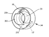
粉体容器9,10から排出されたトナー、現像剤を循環現像剤と混合するための混合容器11は、現像剤転回スペース15を形成する転回本体13と蓋側板14とからなる。蓋側板14は転回本体13に回転自在に嵌合されていて、現像剤転回スペース15の一端面となり、図3に示されるように、転回本体13側(即ち、図3での左手前側)から見て第2象限及び第4象限に位置した孔16,17及び中央開口を備えた平板部28と、これを取り囲む円筒部29と、並びに平板部中央開口を囲むように平板部28から転回本体側に突出した供給支持羽根30、回収支持羽根31を備えている。流出孔16と流入孔17を上下垂直位置でなく第2象限及び第4象限に位置させることによって、搬送スクリュー22端部をスペース効率に優れた箇所に位置させることができる。
【0018】
また転回本体13は、図4に示されるように、比較的大きな中央開口を有した筒状を有する。その外周側壁には不図示の駆動部からの回転駆動を伝達するためのギヤ34が取り付けられており、現像剤を循環系に戻す場合には例えば矢印Aの方向に回転する。また転回本体13の内面には、トナー乃至現像剤をトナー/現像剤搬送装置へ送り出すための現像剤供給部35と、回収現像剤を容器内に戻す現像剤回収部36とが形成されている。これら現像剤供給部35と現像剤回収部36とは少なくとも1対設けられる(図示の例では2対)。現像剤供給部35は、転回本体13の外周側壁内面と蓋側板14の支持羽根30の外側を摺擦する内周壁とで規定され、それら壁の間の底面は現像剤供給回転(A方向回転)の際の下流側が上流側より高くなっていて、斜面を構成している。現像剤回収部36は、その底面が現像剤供給部の上記上流端と同じ高さの平坦面であり、現像剤供給部の内壁の延長部によって囲い部37を形成し、現像剤回収の際の回転(B方向回転)の際に回収現像剤を搬送する。
【0019】
図2及び図4では略してあるが、転回本体13の現像剤供給部35及び/又は現像剤回収部36の傾斜乃至平坦底面には現像剤撹拌手段が設けられている。これを図5において断面的に示す。即ち、現像剤供給部35、現像剤回収部36の底面から蓋側板14の方へ突き出た現像剤撹拌部片38である。これは例えば円柱状に形成されており、平面的に見れば、図6のようになる。現像剤撹拌部片は、図7に示されるように、羽根形状(平細片形状)の部片38’であってもよく、また回収時に現像剤を汲み上げることとなる側を開口した断面U形状になった部片38’’を少なくとも部分的に備えれば、供給時にはそのU形状で供給トナー/現像剤をかきわけ、開口側にスペースを作ることで、そのスペース部に撹拌されているトナー/現像剤が流れ込み、撹拌効果が向上することとなる。また回収時にはトナー/現像剤を汲み上げることができ、閉鎖栓40を介しての容器3への現像剤回収が一層効率良くできる。図7から認識されるように、現像剤を汲み上げながら、閉鎖栓上に現像剤を振り落とすために、撹拌部片38’’のU断面は、回転中心に近い側が短く形成されているのがよい。同様の効果を奏するように、平細片部片38’も傾いて底面に設けられているのが好都合である。また転回本体13の外周側壁の内側に図7に示されたような傾き撹拌部位39を備えているようにすることができる。その傾きは、転回本体13の回収回転時に現像剤の汲み上げを補助し、供給回転時にはトナー/現像剤を中心範囲に寄せて蓋側板の孔16からの排出を補助することができるように付けられている。
【0020】
図6や図7の例では各撹拌部片が現像剤供給部35、現像剤回収部36の底面に規則的に分布しているが、不規則なレイアウト(図示せず)で配置し、現像剤/トナーを当該撹拌部片に不規則に接触させて撹拌性の向上を図るようにすることもできる。更に現像剤供給部35に備えられた現像剤撹拌部片38は図6では2列の同一円周に配列されているが、転回本体13がA方向に回転する際にトナー/現像剤が撹拌されやすいように例えば互い違いずらされた位置関係となるように配置されてもよい。また撹拌部片を例えばゴムのようなフレキシビリティのある材質で構成し、しかも転回部材13を蓋側板14と組み合わせた時に、当該撹拌部片の先端が蓋側板の平板部28に突き当たるような長さを有していれば、当該平板部に付着したトナー/現像剤を掻き取ることができ、また現像剤転回スペース15内のトナー/現像剤の粗密によって撹拌部片が不規則に動くことになって撹拌・混合性を高めることが可能となる。
【0021】
図8にシャッター6を取り付けた粉体収容容器3の外観を示す。シャッター6には、ケース用シャッターと係合するための突出部41、窪み部42が形成されている。これら突出部、窪み部は図示のように両方備えられていてもよいが、ケース側の切欠き部、突起部に合わせてどちらか一方だけが形成されていてもよい。蓋側板の孔に対応する孔44,45がシャッター平面部に形成されている。容器が装置本体にセットされ、突出部41とケース用シャッターの周辺切欠き部(図示せず)、窪み部42とケース用シャッター突起部(図示せず)の係合によって、シャッターの回動につれて孔の位置がずれ、蓋側板の孔16,17が開口し、結局、孔16と17はそれぞれ孔26と25と連通する。その際、シャッターの回動で誘導ガイド(図示せず)の位置も動き、栓40の先端に係合して、当該栓を容器より引き出すことになる。
【0022】
これら蓋側板14と転回本体13とが嵌合すると、蓋側板14の平板部28、転回本体13の供給部及び回収部の底面、転回本体13の周囲側壁及び内周壁、並びに蓋側板14の支持羽根30,31によって、現像剤転回スペース15が規定される。転回本体13の回転の際に、現像剤が入り込まないように、蓋側板14と転回本体13の間に第1シール部材48が装着されている(図2)。このシール部材48はゴム系のVリング、Gシール、あるいはそれらの代替物、例えばスポンジ等である。粉体収容容器3をトナー/現像剤補給装置にセットする際の保持及びシールのために、転回本体13の内周縁部にも第2シール部材49が付され、また蓋40と蓋側板14の間にも第3シール部材50が付されている。
【0023】
本実施例での一連の動作を以下に説明する。例えば、現像装置2のトナー濃度が低下し、トナー補給が必要になったにもかかわらず、粉体収容容器3にトナーが無いと判断された場合には、ユーザーに容器3の交換を促す。新しい容器3が装着されると、既述のようにして栓40を開く。栓40を開くにあたり、不図示の駆動部からギヤ34を介して転回本体13に駆動を与え、A方向に回転する。同時に粉体収容容器3も同じA方向に回転され、第1粉体容器9からトナーを転回スペース15へ排出する。第1粉体容器9の内周面に付けられた螺旋突起の螺旋状態(傾き)によっては、B方向に回転することでトナーを排出する場合もある。粉体収容容器の駆動は独立の駆動部によってなされてもよいが、伝動機構を介して転回本体の駆動をもらうようにしてもよい。また第2粉体容器10の内周面に付けられた螺旋突起の傾きが第1粉体容器9のものと同様の向きであれば、トナー補給の際に同時に現像剤も供給されることとなる。また螺旋突起の傾きが逆向きであれば、トナー補給の場合とは逆に回転することで現像剤を転回スペース15へ排出できる。
【0024】
開口から排出されたトナー乃至現像剤は転回スペース15に落下し、当該転回本体13のA方向回転によって、現像剤供給部35内で撹拌部片38によって撹拌作用を受けながら上方へ且つ供給部の斜面に沿ってトナー/現像剤搬送装置4に近づく方向へ移動され、やがて各々の側壁上側に設けられた孔16,44,26を介して回転駆動する第2搬送スクリュー22上へ送り出される。このとき、現像剤供給部35によって汲み上げられたトナー乃至現像剤の一部は、流出孔16から排出されず、転回スペース15にとどまる。これによって、当該残留トナー乃至現像剤が、粉体収容容器3から転回スペース15に新たに供給される新トナー/現像剤及び(あるいは)流入孔17から流入する循環現像剤と混合され、混合性が高まる。特に、現像剤供給部35と現像剤回収部36とが一対だけ設けられている場合のように、次に汲み上げられるトナー乃至現像剤が既に転回スペース15に準備されているときには、前記残留トナー乃至現像剤が自由落下によってふりそそぐ結果となり、トナーと現像剤との混合性がさらに高まる。これは、現像剤がトナーに比して大きな比重をもつために、トナーの上から現像剤がふりそそぐと、トナーの間をぬって現像剤がトナーの集団の内部に沈み込み、トナーと混合されるからである。そして再び上昇する際に撹拌部片38による撹拌混合作用を受けて一段と混合がすすむこととなる。
【0025】
トナー乃至現像剤を転回スペースの現像剤供給部35で回転搬送する際に、当該トナー乃至現像剤は傾斜底部と周囲側壁と内周側壁で規定された空間にあって搬送されるものであり、したがって内周側壁と摺擦する供給支持羽根30を省略することも可能である。第2搬送スクリュー22及び第1搬送スクリュー21は、粉体収容容器3が回転駆動する際には、少なくとも同時に駆動し始めているので、現像装置2から現像剤を循環搬送しており、特にトナーを補給する場合には、混合容器11の転回スペース15において前記の方法により混合されたトナーと現像剤とが現像装置2に至るまでにさらに混ざり合い、現像装置2内でのトナー濃度のむらを最低限に抑え込むことができる。
【0026】
トナーを所定量供給した後、粉体収容容器3の回転は停止する。この際、転回本体13並びに第1搬送スクリュー21及び第2搬送スクリュー22は駆動を停止してもよいし、駆動させたままにしておいてもよい。第1搬送スクリュー21及び第2搬送スクリュー22が現像装置2内の一部を構成している場合には、現像装置2内の現像剤攪拌の観点から常に駆動させておくのがよい。またケース用シャッター5を回動してケース23の孔25,26を塞ぎ、第1搬送スクリュー21及び第2搬送スクリュー22のみを駆動させてもよい。
【0027】
第1粉体容器9から新トナーがすべて排出されると、空になった当該粉体容器9は劣化現像剤のための回収容器として用いられることになる。劣化現像剤の回収の場合には、第1搬送スクリュー21及び第2搬送スクリュー22をトナー乃至現像剤供給の場合と同じように駆動するとともに、転回本体13をトナー乃至現像剤供給の場合と逆にB方向に回転させる。閉鎖栓は所定の回収位置に配置される。現像剤回収のタイミングは、現像装置2内の磁気型トナー濃度センサーや光学式トナー濃度センサー、感光体上でトナー濃度を感知するセンサー等によってトナー濃度の低下に伴いトナー補給が必要になった時点に合わせるのが合理的である。各種センサーによりトナー濃度の低下を判断し第1粉体容器9内にトナーがなくなった場合に現像剤回収モードとする。
【0028】
現像装置2から送り出された劣化現像剤は、第2搬送スクリュー22下方に形成された落としスペース24からケース23等の側壁下側に設けられた孔25,45,17を通って、回転する転回スペース15に入り込む。転回スペース15に入った現像剤は、転回本体13の周囲側壁と回収支持羽根31で囲まれた空間に溜り、現像剤回収部36の囲い部37あるいはU形状撹拌部材38’’によって上方に持ち上げられ、やがて回収支持羽根31の途切れる位置で落下し、栓40の羽根部で拾われ、円錐面を滑って第1粉体容器9へ回収される。この際、第1粉体容器9をトナー補給の際と逆向きに回転することで内周螺旋突起の作用により回収現像剤が容器奥側へ取り込まれる。転回スペース15と第1粉体容器9に回収された劣化現像剤の量が、第2粉体容器10に始め収容され現像装置2に供給された新現像剤の量に等しくなった時点で回収を終了する。現像剤の新旧交換は、現像装置2の容量中の一部の交換が一般的であるが、全量交換することも可能である。回収終了後にはトナーエンドとしてユーザーに容器の交換を促すことが前述した通りである。その場合、ケース用シャッター、容器用シャッターを回動してそれぞれの孔を塞ぐことで、現像剤漏れを完全に防ぐことができる。
【0029】
なお、第2粉体容器10に収容された新現像剤と等しい量の循環現像剤が転回スペース15に存在している場合には、上記のように回収動作を行わなくとも、粉体収容容器3を取り出すことで粉体混合容器部材の転回スペースに入った交換されるべき必要量の現像剤が自動的に回収されることになる。
【0030】
【発明の効果】
本発明によれば、回転自在に嵌合される転回部材と蓋側板とで成り、現像剤/トナー収容容器に嵌め合わされるべきトナー/現像剤用混合容器にして、上記転回部材は、現像剤/トナー収容容器の開口に対応する中央開口を有した筒状であって、その内面には現像剤供給部と現像剤回収部を有し、現像剤供給部は、周囲側壁と内周壁とで規定され供給回転方向下流側にいくに従い浅くなる底部を有する空間であり、現像剤回収部は、その底面が現像剤供給部の上流端と同じ高さの平坦面で、上記現像剤供給部の下流側を構成する壁部と上記転回部材の周囲側壁とによって囲い部を形成しており、上記供給回転と逆向きの回収回転の際に回収現像剤を回転移送可能とし、上記蓋側板は、上記転回部材の周囲側壁と内周壁の各上縁端に摺擦して閉鎖供給スペースを形成可能とする平板部と、上記転回部材の供給回転に伴いトナー/現像剤を搬出入する流出孔と流入孔を有するようなトナー/現像剤用混合容器において、上記転回部材と上記蓋部材を嵌合することで画定され上記現像剤供給部及び/又は現像剤回収部を構成する転回スペースに、現像剤攪拌部片が突出して備えられているので、転回部材の回転に際して現像剤の攪拌混合が行われることになって、別個に攪拌装置を設ける必要がなくなる。特に現像剤攪拌部片が転回スペース内で互い違いにずらされた位置関係をもって配置されていたり、転回部材に固着された上記現像剤攪拌部片がフレキシブルで、その先端が上記蓋側板の平板部表面を擦りうる長さを有していれば、混合性が一層向上する。
【0031】
また現像剤攪拌部片が現像剤汲み上げ手段を兼ねていれば、現像剤回収時に現像剤汲み上げを効率的に行うことができ、更に当該現像剤汲み上げ手段が、上記転回部材の回収回転の際に汲み上げ側を開口した断面U形状を有していれば、現像剤回収を効率化できる。
【図面の簡単な説明】
【図1】本発明に係るトナー/現像剤供給装置と現像装置の位置関係を示すもので、トナー/現像剤搬送装置を部分的に開放した概略図である。
【図2】本発明に係るトナー/現像剤用の混合容器の構成を示す概略断面図である。
【図3】混合容器を構成する蓋側板の斜視図である。
【図4】混合容器を構成する転回本体の斜視図である。
【図5】転回本体に付された撹拌部片を示す部分断面図である。
【図6】図5のC視方向から見た転回本体の部分平面図である。
【図7】図6とは異なる形状の撹拌部片を付した構成の部分平面図である。
【図8】シャッターが取り付けられた粉体収容容器の斜視図である。
【符号の説明】
13 転回本体
14 蓋側板
15 現像剤転回スペース
35 現像剤供給部
36 現像剤回収部
38 現像剤撹拌部片[0001]
TECHNICAL FIELD OF THE INVENTION
The present invention is attached to a developing device in an image forming apparatus such as an analog / digital copying machine, a facsimile, and a printer, and in particular, an electrophotographic image forming apparatus that forms an image using a two-component developer including a carrier and a toner. The present invention relates to a mixing container that constitutes a toner / developer supply device. The toner / developer supply device can automatically perform toner replenishment accompanying toner consumption and replacement of a carrier that deteriorates with time.
[0002]
[Prior art]
As a bottle for supplying a toner to a developing device, for example, a bottle having a configuration disclosed in Japanese Patent Application Laid-Open Nos. 60-159768, 7-20705, and 7-159768 is known. In the configurations disclosed in these publications, the toner contained inside is discharged in a horizontal installation state by the action of a spiral fin (projection) provided inside the bottle container during rotation. However, these bottles are used only for toner supply and have no other uses.
[0003]
In addition, in the two-component developing device, in addition to toner replenishment to supplement consumption, supply of a developer containing a new carrier and replacement of a used developer containing the deteriorated carrier for replacement of the deteriorated carrier are required. is necessary. In particular, regarding replacement of the developer, in order to suppress fluctuations in image quality, partial replacement at regular intervals is becoming the mainstream, instead of replacing the entire amount every lifetime. Regarding toner replenishment and developer replacement, for example, Japanese Patent Application Laid-Open No. 4-29271 discloses a developer supply / discharge mechanism including a unit for discharging a part of a used developer and a unit for supplying a new developer. In this mechanism, the used developer is collected after supplying the developer to a container containing the new developer. However, according to the technology disclosed in this publication, the serviceman simply re-attaches the empty container to a collection position different from the supply position, and therefore, the container is automatically attached to the container after the developer is supplied at the supply position. However, it is not necessary to collect the used developer, and it is necessary to mount two containers in the apparatus, resulting in an increase in the size of the apparatus.
[0004]
Japanese Patent Application Laid-Open No. 2-6978 discloses a toner container in which a replenishing container portion and a collecting container portion have an integral structure and are detachably attached to a developing device. In this container, the toner is collected in a separated collecting agent storage section. Therefore, a separate useless space called a collecting section is required as a toner supply container, so that the size of a device to be mounted is increased, and an inventory space is increased. It also requires useless space.
[0005]
Therefore, it is required that the deteriorated used developer is automatically collected without increasing the size of the apparatus and without bothering a service person or a user. From the viewpoint of effective use of space, it is desirable to collect the deteriorated used developer into the toner container for storing the replenished toner after use (after replenishment). For example, in the technique of JP-A-60-159768, a spiral fin is provided internally, and in the technique of JP-A-7-20705, a part of the inner surface of the container shoulder further has a diameter larger than the diameter of the opening. Although it has a shape protruding from the inner surface of the shoulder to the edge of the opening, these effective means for discharging toner also cause a decrease in performance with respect to developer collection. As a result, it may happen that the amount of the collection to be collected cannot be collected.
[0006]
The present applicant has previously described a cylindrical container which is concentric with the container and is integrated into the central space of a container having an annular portion, which is composed of two storage containers, and a concentric opening is formed on the same side of each container. (Japanese Patent Application Laid-Open No. 8-185033). Further, in order to effectively use the integrated bottle, the inventors have further proposed a toner supply and developer supply / recovery mechanism disposed between the integrated bottle and the developing device (Japanese Patent Application No. 7-1995). 262984). This is provided with a supply section for sending out the toner / developer discharged from the bottle to the developing section by a rotation operation, and a recovery section for lifting up the developer sent from the development section by a rotation operation. A turning member having a space defined by the peripheral wall and having a bottom portion which becomes shallower toward the downstream side in the supply rotation direction and a scooping portion capable of rotatably transporting the developer at the time of recovery rotation, and a peripheral side wall and an inner wall of the turning member; A flat plate portion that can form a supply space by rubbing against each upper edge of the peripheral wall, and a toner / container having a cover side plate having a supply hole and a recovery hole for carrying in / out the toner / developer with the rotation of the turning member. This is a developer supply device.
[0007]
However, when toner / developer is supplied using the bottle and the replenishing device as described above, the toner / developer discharged from the bottle is lifted by the rotation of the turning member and is supplied to the developing unit. So we can not expect much about the mixing effect. In particular, when the developer is returned directly from the developing unit to the toner / developer replenishing device and circulated, the mixing of the toner / developer is regarded as being performed in the developing unit, and the density unevenness may not be eliminated. .
[0008]
[Problems to be solved by the invention]
Therefore, the present invention provides a toner / developer mixing container which can perform toner / developer supply and developer collection in a common member, and can positively enhance the mixing property between the replenishment toner and the circulating developer. The task is to provide
[0009]
[Means for Solving the Problems]
According to the present invention, there is provided a toner / developer mixed container to be fitted into a developer / toner storage container, comprising a turning member rotatably fitted and a lid side plate according to the present invention. Has a central opening corresponding to the opening of the developer / toner storage container, and has a developer supply section and a developer recovery section on the inner surface thereof. A space defined by the inner peripheral wall and having a bottom portion which becomes shallower toward the downstream side in the supply rotation direction, and wherein the developer recovery portion has a flat bottom surface having the same height as the upstream end of the developer supply portion; An enclosure is formed by a wall constituting the downstream side of the developer supply unit and a peripheral side wall of the turning member, and the collected developer can be rotatably transferred at the time of the collection rotation in the opposite direction to the supply rotation, The lid side plate is located on each of the peripheral side wall and the inner peripheral wall of the turning member. A toner / developer mixing container having a flat plate portion capable of forming a closed supply space by rubbing against an end, and an outflow hole and an inflow hole for carrying in / out the toner / developer with the supply member rotating. In the above, the developer stirring portion piece is provided so as to protrude in a turning space defined by fitting the turning member and the lid member and constituting the developer supply portion and / or the developer collecting portion. Will be solved.
[0010]
It is effective if the developer stirring sections are arranged in a staggered positional relationship within the turning space. It is more effective if the developer stirring section fixed to the turning member is flexible and its tip has a length that can rub the flat plate surface of the lid side plate.
[0011]
If the developer stirring section also serves as a developer pumping unit, it is preferable when the developer is collected. Further, it is more preferable that the developer pumping means has a U-shaped cross section that is open on the pumping side when the rotating member is recovered and rotated.
[0012]
BEST MODE FOR CARRYING OUT THE INVENTION
The details of the present invention will be described based on the illustrated embodiment.
FIG. 1 shows a developing
[0013]
As shown, the toner / developer conveying device 4 has a first conveying
[0014]
The structure of the
[0015]
Further, the respective openings of the first powder container 9 and the
[0016]
The closure plug 40 first closes the respective end openings of the first powder container 9 and the
[0017]
The mixing container 11 for mixing the toner and the developer discharged from the
[0018]
Further, as shown in FIG. 4, the turning
[0019]
Although not shown in FIGS. 2 and 4, a developer stirring unit is provided on the inclined or flat bottom surface of the
[0020]
In the examples of FIGS. 6 and 7, the respective stirring sections are regularly distributed on the bottom surfaces of the
[0021]
FIG. 8 shows the appearance of the
[0022]
When the
[0023]
A series of operations in this embodiment will be described below. For example, if it is determined that there is no toner in the
[0024]
The toner or developer discharged from the opening falls into the turning
[0025]
When the toner or the developer is rotated and transported by the
[0026]
After a predetermined amount of toner is supplied, the rotation of the
[0027]
When all the new toner is discharged from the first powder container 9, the empty powder container 9 is used as a collection container for the deteriorated developer. In the case of collecting the deteriorated developer, the
[0028]
The deteriorated developer sent out from the developing
[0029]
When the same amount of the circulating developer as the new developer stored in the
[0030]
【The invention's effect】
According to the present invention, a toner / developer mixed container to be fitted into a developer / toner container, which is composed of a turning member rotatably fitted and a lid side plate, wherein the turning member is a developer. / A cylindrical shape having a central opening corresponding to the opening of the toner container, and having a developer supply portion and a developer recovery portion on its inner surface, the developer supply portion having a peripheral side wall and an inner peripheral wall. A space having a bottom that is defined and becomes shallower toward the downstream side in the supply rotation direction. The developer recovery unit is a flat surface whose bottom surface is the same height as the upstream end of the developer supply unit. An enclosure is formed by the wall constituting the downstream side and the peripheral side wall of the turning member, and the collected developer can be rotatably transferred during the collection rotation in the opposite direction to the supply rotation, and the lid side plate is Close the upper and lower peripheral edges of the turning member In a toner / developer mixing container having a flat plate portion capable of forming a supply space and an outflow hole and an inflow hole for carrying in / out the toner / developer with the supply / rotation of the rotation member, Since the developer agitating portion is protrudingly provided in the turning space defined by fitting the lid member and constituting the developer supply portion and / or the developer collecting portion, the developer is rotated when the turning member rotates. Is performed, and it is not necessary to provide a separate stirring device. In particular, the developer stirring section is arranged in a staggered positional relationship within the turning space, or the developer stirring section fixed to the turning member is flexible, and its tip is a flat plate surface of the lid side plate. If the length is such that it can be rubbed, the mixing property is further improved.
[0031]
Further, if the developer stirring section also serves as a developer pumping means, the developer can be efficiently pumped at the time of collecting the developer, and further, the developer pumping means can be used at the time of collecting and rotating the turning member. If the section has a U-shape with an opening on the pumping side, the efficiency of developer collection can be increased.
[Brief description of the drawings]
FIG. 1 is a schematic diagram showing a positional relationship between a toner / developer supply device and a developing device according to the present invention, in which a toner / developer conveying device is partially opened.
FIG. 2 is a schematic sectional view showing the configuration of a toner / developer mixing container according to the present invention.
FIG. 3 is a perspective view of a lid side plate constituting the mixing container.
FIG. 4 is a perspective view of a turning main body constituting the mixing container.
FIG. 5 is a partial cross-sectional view showing a stirring piece attached to the turning main body.
FIG. 6 is a partial plan view of the turning main body as viewed from a direction C in FIG. 5;
FIG. 7 is a partial plan view of a configuration provided with a stir piece having a shape different from that of FIG. 6;
FIG. 8 is a perspective view of a powder container to which a shutter is attached.
[Explanation of symbols]
13 turning
Claims (5)
上記転回部材は、現像剤/トナー収容容器の開口に対応する中央開口を有した筒状であって、その内面には現像剤供給部と現像剤回収部を有し、現像剤供給部は、周囲側壁と内周壁とで規定され供給回転方向下流側にいくに従い浅くなる底部を有する空間であり、現像剤回収部は、その底面が現像剤供給部の上流端と同じ高さの平坦面で、上記現像剤供給部の下流側を構成する壁部と上記転回部材の周囲側壁とによって囲い部を形成しており、上記供給回転と逆向きの回収回転の際に回収現像剤を回転移送可能とし、
上記蓋側板は、上記転回部材の周囲側壁と内周壁の各上縁端に摺擦して閉鎖供給スペースを形成可能とする平板部と、上記転回部材の供給回転に伴いトナー/現像剤を搬出入する流出孔と流入孔を有する
ようなトナー/現像剤用混合容器において、
上記転回部材と上記蓋部材を嵌合することで画定され上記現像剤供給部及び/又は現像剤回収部を構成する転回スペースに、現像剤攪拌部片が突出して備えられていることを特徴とする、混合容器。A toner / developer mixed container to be fitted into the developer / toner storage container, which comprises a turning member rotatably fitted and a lid side plate,
The turning member has a cylindrical shape having a central opening corresponding to the opening of the developer / toner storage container, and has a developer supply unit and a developer collection unit on the inner surface thereof. A space defined by the peripheral side wall and the inner peripheral wall and having a bottom portion which becomes shallower toward the downstream side in the supply rotation direction, and the developer recovery portion is a flat surface whose bottom surface is the same height as the upstream end of the developer supply portion. An enclosure is formed by a wall constituting the downstream side of the developer supply unit and a peripheral side wall of the turning member, and the collected developer can be rotationally transferred at the time of the collection rotation in the opposite direction to the supply rotation. age,
The lid side plate has a flat plate portion capable of forming a closed supply space by rubbing each upper edge of the peripheral side wall and the inner peripheral wall of the turning member, and carries out toner / developer with the supply rotation of the turning member. In a toner / developer mixing container having an inlet outlet and an inlet,
A developer stirring section is protruded and provided in a turning space defined by fitting the turning member and the lid member and constituting the developer supply section and / or the developer recovery section. Do, mixing container.
Priority Applications (1)
| Application Number | Priority Date | Filing Date | Title |
|---|---|---|---|
| JP00969697A JP3592019B2 (en) | 1997-01-22 | 1997-01-22 | Mixer container for toner / developer |
Applications Claiming Priority (1)
| Application Number | Priority Date | Filing Date | Title |
|---|---|---|---|
| JP00969697A JP3592019B2 (en) | 1997-01-22 | 1997-01-22 | Mixer container for toner / developer |
Publications (2)
| Publication Number | Publication Date |
|---|---|
| JPH10207208A JPH10207208A (en) | 1998-08-07 |
| JP3592019B2 true JP3592019B2 (en) | 2004-11-24 |
Family
ID=11727398
Family Applications (1)
| Application Number | Title | Priority Date | Filing Date |
|---|---|---|---|
| JP00969697A Expired - Fee Related JP3592019B2 (en) | 1997-01-22 | 1997-01-22 | Mixer container for toner / developer |
Country Status (1)
| Country | Link |
|---|---|
| JP (1) | JP3592019B2 (en) |
-
1997
- 1997-01-22 JP JP00969697A patent/JP3592019B2/en not_active Expired - Fee Related
Also Published As
| Publication number | Publication date |
|---|---|
| JPH10207208A (en) | 1998-08-07 |
Similar Documents
| Publication | Publication Date | Title |
|---|---|---|
| JP3352569B2 (en) | Supply cartridge for two-component developer and supply device provided with the cartridge | |
| JP3541691B2 (en) | Image forming apparatus and developer container | |
| JP4423140B2 (en) | Toner container, toner supply device, and image forming apparatus | |
| JPH11143196A (en) | Image forming device | |
| JP2008129336A (en) | Developer cartridge, developing device, and image forming apparatus | |
| JP3481772B2 (en) | Toner / developer supply device | |
| JP3537602B2 (en) | Toner / developer supply device | |
| JP3592019B2 (en) | Mixer container for toner / developer | |
| JP3492463B2 (en) | Toner / developer supply / collection mechanism and its replenishing device | |
| JP5648598B2 (en) | Image forming apparatus and toner bottle | |
| JP3315569B2 (en) | Toner / developer supply device | |
| JP4676079B2 (en) | Developing device and process cartridge | |
| JP3310506B2 (en) | Toner / developer supply device and toner / developer supply structure | |
| JPH11119530A (en) | Developing device | |
| JP3267455B2 (en) | Image forming device | |
| JP4687191B2 (en) | Developing device, process cartridge using the same, and image forming apparatus | |
| JP4687190B2 (en) | Developing device, process cartridge using the same, and image forming apparatus | |
| JPH10319698A (en) | Toner/developer replenishing device | |
| JP4770224B2 (en) | Developing device, process cartridge using the same, and image forming apparatus | |
| JP4004011B2 (en) | Developing device, image forming apparatus, and process cartridge | |
| JPH10293449A (en) | Toner and developer device | |
| JP3290294B2 (en) | Toner replenishing device and image forming apparatus having the toner replenishing device | |
| JP2006267933A (en) | Developing device, and process cartridge and image forming apparatus using the same | |
| JPH05313491A (en) | Toner replenishing device | |
| JP4383731B2 (en) | Rotating developer |
Legal Events
| Date | Code | Title | Description |
|---|---|---|---|
| A977 | Report on retrieval |
Free format text: JAPANESE INTERMEDIATE CODE: A971007 Effective date: 20040308 |
|
| A131 | Notification of reasons for refusal |
Free format text: JAPANESE INTERMEDIATE CODE: A131 Effective date: 20040316 |
|
| A521 | Written amendment |
Free format text: JAPANESE INTERMEDIATE CODE: A523 Effective date: 20040514 |
|
| TRDD | Decision of grant or rejection written | ||
| A01 | Written decision to grant a patent or to grant a registration (utility model) |
Free format text: JAPANESE INTERMEDIATE CODE: A01 Effective date: 20040810 |
|
| A61 | First payment of annual fees (during grant procedure) |
Free format text: JAPANESE INTERMEDIATE CODE: A61 Effective date: 20040824 |
|
| FPAY | Renewal fee payment (event date is renewal date of database) |
Free format text: PAYMENT UNTIL: 20080903 Year of fee payment: 4 |
|
| FPAY | Renewal fee payment (event date is renewal date of database) |
Free format text: PAYMENT UNTIL: 20080903 Year of fee payment: 4 |
|
| FPAY | Renewal fee payment (event date is renewal date of database) |
Free format text: PAYMENT UNTIL: 20090903 Year of fee payment: 5 |
|
| FPAY | Renewal fee payment (event date is renewal date of database) |
Free format text: PAYMENT UNTIL: 20090903 Year of fee payment: 5 |
|
| FPAY | Renewal fee payment (event date is renewal date of database) |
Free format text: PAYMENT UNTIL: 20100903 Year of fee payment: 6 |
|
| FPAY | Renewal fee payment (event date is renewal date of database) |
Free format text: PAYMENT UNTIL: 20110903 Year of fee payment: 7 |
|
| FPAY | Renewal fee payment (event date is renewal date of database) |
Free format text: PAYMENT UNTIL: 20120903 Year of fee payment: 8 |
|
| FPAY | Renewal fee payment (event date is renewal date of database) |
Free format text: PAYMENT UNTIL: 20130903 Year of fee payment: 9 |
|
| LAPS | Cancellation because of no payment of annual fees |