JP3592002B2 - Combine grain discharger - Google Patents
Combine grain discharger Download PDFInfo
- Publication number
- JP3592002B2 JP3592002B2 JP27312296A JP27312296A JP3592002B2 JP 3592002 B2 JP3592002 B2 JP 3592002B2 JP 27312296 A JP27312296 A JP 27312296A JP 27312296 A JP27312296 A JP 27312296A JP 3592002 B2 JP3592002 B2 JP 3592002B2
- Authority
- JP
- Japan
- Prior art keywords
- conveyor
- screw conveyor
- drive mechanism
- feed screw
- grain
- Prior art date
- Legal status (The legal status is an assumption and is not a legal conclusion. Google has not performed a legal analysis and makes no representation as to the accuracy of the status listed.)
- Expired - Fee Related
Links
Images


Landscapes
- Threshing Machine Elements (AREA)
- Screw Conveyors (AREA)
Description
【0001】
【発明の属する技術分野】
本発明は、縦送りコンベアの上部に、横送りコンベアを、起伏駆動機構の作動により横軸芯周りに起伏揺動自在で、かつ、旋回駆動機構の作動により縦軸芯周りに旋回揺動自在となるように装備するとともに、前記横送りコンベアを、伸縮駆動機構の作動により、その送り方向に伸縮自在となるように構成したコンバインの穀粒排出装置に関する。
【0002】
【従来の技術】
上記のようなコンバインの穀粒排出装置としては、例えば、特開平2‐120134号公報や特開平2‐195820号公報などで開示されているように、上記構成によって、穀粒収集箇所(例えば、トラックの荷台など)に対する横送りスクリューコンベアの先端部に設けられた穀粒排出口の遠近方向での適正な位置合わせを、機体を移動させることなく横送りスクリューコンベアの操作だけで容易に行えるようにするとともに、圃場と穀粒収集箇所との間に比較的に高い畦あるいは畦および用水などが介在していることにより機体と穀粒収集箇所との離間距離が長くなる場合であっても、横送りスクリューコンベアをその先端部が機体外方に大きく突出する状態に伸長させることによって、圃場から穀粒収集箇所への穀粒排出を行えるようにしているものがある。
【0003】
【発明が解決しようとする課題】
従来、これらコンバインの穀粒排出装置において、横送りスクリューコンベアを穀粒収集箇所へ移動させるに当たっては、格納位置にある横送りスクリューコンベアを上昇操作した後、旋回操作、その後、伸長させて横送りスクリューコンベアを所望の穀粒収集箇所へ移動させている。
【0004】
ところで、これらコンバインの穀粒排出装置において、横送りスクリューコンベアを昇降作動させるシリンダ、或いは、横送りスクリューコンベアを旋回させる旋回モータ、さらに、横送りスクリューコンベアを伸長作動させるシリンダの作動速度には停止時のショック等により限界があり、あまり素早く横送りスクリューコンベアを穀粒収集箇所に移動させることができないものとなっている。
【0005】
本発明は、横送りスクリューコンベアの穀粒収集箇所への移動を迅速に行わせて穀粒排出作業時間の短縮化を図ることを目的とする。
【0006】
【課題を解決するための手段】
請求項1に記載の発明は、縦送りコンベアの上部に、横送りコンベアを、起伏駆動機構の作動により横軸芯周りに起伏揺動自在で、かつ、旋回駆動機構の作動により縦軸芯周りに旋回揺動自在となるように装備するとともに、前記横送りコンベアは前記縦送りコンベアに連通接続された第一コンベア部とこの第一コンベア部に連通接続された第二コンベア部を備え、伸縮駆動機構の作動により、第一コンベア部に対して第二コンベア部を摺動させてその送り方向に伸縮自在となるように構成したコンバインの穀粒排出装置であって、格納位置にある横送りコンベアに穀粒排出指令を与えると、前記横送りコンベアが排出位置に向かって移動中に、横送りコンベアの第一コンベア部と第二コンベア部との穀粒移送経路が最も延びた最大伸長状態よりも短い設定量伸長状態となるように前記伸縮駆動機構の作動を制御する制御手段を装備してある。
【0007】
〔作用〕
上記請求項1記載の発明によると、横送りコンベアを穀粒収集箇所に移動させる際には、格納位置にある横送りコンベアに対して穀粒排出指令としての上昇指令を与えると、その上昇操作指令に基づいて伸縮駆動機構の作動によって、上昇と伸長が同時に行われ、上昇と伸長を別々に行なう場合に比して横送りコンベアの穀粒収集箇所への移動時間を短くし得る。しかも、最大伸長状態よりも短い設定量だけ伸長させるので、最大限伸長させる場合のように長くなり過ぎて旋回が行ない難くなったり、穀粒収集箇所で短縮させるような無駄も無くなる。
〔効果〕
上記構成によれば、横送りコンベアの穀粒収集箇所への移動時間を短くし得て穀粒排出作業時間を短くし得る。
【0008】
【発明の実施の形態】
以下、本発明の実施の形態を図面に基づいて説明する。
【0009】
図1には自脱型コンバインの全体側面が、図2には自脱型コンバインの全体平面が夫々示されており、このコンバインは、左右一対のクローラ式走行装置1を備えた走行機体2、走行機体2の前部に装着された刈取部3、刈取部3にて刈り取られた穀稈を脱穀して穀粒を選別回収する脱穀装置4、脱穀装置4にて選別回収された穀粒を貯留するグレンタンク5、および、グレンタンク5に貯留された穀粒をトラックTの荷台Taなどの穀粒収集箇所に排出する穀粒排出装置6などによって構成されている。
【0010】
前記穀粒排出装置6は、グレンタンク5の底部に前後方向に沿う状態に配備された底部スクリューコンベヤ7、底部スクリューコンベヤ7の搬送終端部から上方に向けて延設された縦送りスクリューコンベヤ8、縦送りスクリューコンベヤ8の上部に横軸芯X周りに起伏揺動自在でかつ縦軸芯Y周りに旋回揺動自在に装備されるとともに、その送り方向に伸縮自在に構成された横送りスクリューコンベヤ9、横送りスクリューコンベヤ9を縦送りスクリューコンベヤ8に対して横軸芯X周りに起伏駆動する起伏駆動機構10、横送りスクリューコンベヤ9を縦送りスクリューコンベヤ8に対して縦軸芯Y周りに旋回駆動する旋回駆動機構11、および、横送りスクリューコンベヤ9を伸縮駆動する伸縮駆動機構12などによって構成されている。底部スクリューコンベヤ7は、その搬送始端側の端部がグレンタンク5の前部側に露出する状態に延出されており、その延出端には、エンジン(図示せず)からの動力が伝達される入力プーリ13が装着されている。縦送りスクリューコンベヤ8は、コンベヤ本体14と、それを外囲するコンベヤケース15とによって構成されるとともに、コンベヤ本体14がベベルギヤ式連動機構(図示せず)を介して底部スクリューコンベヤ7に連動連結されている。横送りスクリューコンベヤ9は、縦送りスクリューコンベヤ8に連通接続される第一スクリューコンベヤ部9Aと、第一スクリューコンベヤ部9Aの下方に第一スクリューコンベヤ部9Aに対して摺動可能に連通接続される第二ベルトコンベヤ部9Bとによって構成されている。第一スクリューコンベヤ部9Aおよび第二ベルトコンベヤ部9Bは、夫々、コンベヤ本体16,17と、コンベヤ本体16,17を外囲するコンベヤケース18,19によって構成されている。第一スクリューコンベヤ部9Aは、コンベヤ本体16がベベルギヤ式連動機構(図示せず)を介して縦送りスクリューコンベヤ8に連動連結されるとともに、コンベヤケース18が接続ケース20を介して縦送りスクリューコンベヤ8のコンベヤケース15に連結されている。つまり、底部スクリューコンベヤ7、縦送りスクリューコンベヤ8、および、横送りスクリューコンベヤ9は、エンジンからの動力によって駆動されるようになっている。
【0011】
図3および図4に示すように、起伏駆動機構10は、横送りスクリューコンベヤ9の第一スクリューコンベヤ部9Aにおける搬送始端部と接続ケース20とに渡って架設された油圧シリンダ21、および、油圧シリンダ21に対する作動油の流動状態を切り換える電磁制御弁22によって構成されており、操縦部23に装備された上昇スイッチ24または下降スイッチ25の操作により、走行機体2に搭載された制御装置26に対して上昇または下降指令を指令することによって、手動による横送りスクリューコンベヤ9の所望高さへの起伏操作を行えるようになっている。旋回駆動機構11は、接続ケース20に形成された旋回用ギヤ20a、旋回用ギヤ20aに噛合するピニオン27、および、ピニオン27を駆動するように縦送りスクリューコンベヤ8のコンベヤケース15に固定された電動モータ28によって構成されており、操縦部23に装備された左旋回スイッチ29または右旋回スイッチ30の操作により、制御装置26に対して左旋回または右旋回指令を指令することによって、手動による横送りスクリューコンベヤ9の所望位置への旋回操作を行えるようになっている。
【0012】
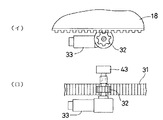
図7,図8に示すように、伸縮駆動機構12は、横送りスクリューコンベヤ9の第一スクリューコンベヤ部9Aにおけるコンベヤケース18の底部に穀粒搬送方向に沿う状態に装着されたラック31、ラック31に噛合するピニオン32、および、ピニオン32を駆動するように第二ベルトコンベヤ部9Bにおけるコンベヤケース19の後部に固定された電動モータ33によって構成されており、操縦部23に装備された伸長スイッチ34または収縮スイッチ35の操作により、制御装置26に対して伸長または収縮指令を指令することによって、手動による横送りスクリューコンベヤ9の所望位置への伸縮操作を行える。
【0013】
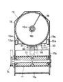
図9に示すように、前記第一スクリューコンベヤ部9Aのコンベヤケース18には、左右の遊転ローラ18aおよび案内レール19aを介して伸縮可能に第二ベルトコンベヤ部9Bのコンベヤケース19が外嵌され、このコンベヤケース19内の下部に前記第二ベルトコンベヤ部9Bが装着されている。
【0014】
図8に示すように、前記ベルトコンベア本体17は、水平軸支した前後一対のプーリドラム51,52に亘って幅広ゴム製の搬送ベルトを巻回張設して構成されており、搬送ベルトの搬送面には搬送方向に対して後退角をもって傾斜する搬送突起17aが備えられている。
【0015】
第一スクリューコンベヤ部9Aのコンベヤケース18に内装されたスクリュー本体16のスクリュー軸16aには、前部を第二コンベアケース19の前壁部に支持させたスプライン軸16bが伸縮可能に嵌入され、このスプライン軸16bの前端と前記ベルトコンベア本体17の前部のプーリドラム51とがベベルケース53に内装のベベルギヤ機構およびチェーン伝動機構54を介して連動連結されており、第一スクリューコンベヤ部9Aのスクリュー16の起動および停止に同調して前記ベルトコンベア本体17が起動および停止されるよう構成されている。
【0016】
図1および図2に示すように、走行機体2には、横送りスクリューコンベヤ9を格納位置Pにて受け止め支持する受止具38が装備されている。前記受止具38には、横送りスクリューコンベヤ9の格納に伴ってオン操作されるとともに、オン信号を制御装置26へ出力する圧力スイッチからなる格納検出センサ39が設けられている。
【0017】
図3および図4に示すように、起伏駆動機構10の油圧シリンダ21には、油圧シリンダ21の伸縮作動量を検出して制御装置26へ出力するスライド式のストロークセンサ40が装備されており、制御装置26は、このストロークセンサ40からの検出情報に基づいて横送りスクリューコンベヤ9の起伏操作角を演算するように構成されている。縦送りスクリューコンベヤ8の搬送終端部には、旋回駆動機構11のピニオン27と噛合するピニオン41を介して電動モータ28の回転数を検出して制御装置26へ出力する回転式のポテンショメータからなる回転センサ42が装備されており、制御装置26は、この回転センサ42からの検出情報に基づいて横送りスクリューコンベヤ9の旋回操作角を演算するように構成されている。図6に示すように、前記伸縮駆動機構12の電動モータ33には、電動モータ33の回転数を検出して制御装置26へ出力する回転式のポテンショメータからなる回転センサ43が装備されており、制御装置26は、この回転センサ43からの検出情報に基づいて横送りスクリューコンベヤ9の伸縮作動量を演算するように構成されている。また、図7および図8に示すように、横送りスクリューコンベヤ9における第一スクリューコンベヤ部9Aの搬送終端部下方には、前記収縮スイッチ35及び伸長スイッチ34による手動操作時に、第二ベルトコンベヤ部9Bの収縮限界位置への到達に伴ってラック31によりオン操作されるとともに、オン信号を制御装置26へ出力するリミットスイッチからなる収縮限界検出センサ44と、第二ベルトコンベヤ部9Bの伸長限界位置への到達に伴って電動モータ33のケースによりオン操作されるとともに、オン信号を制御装置26へ出力するリミットスイッチからなる伸長限界検出センサ46が装備されている。前記制御装置26は、前記収縮限界検出センサ44又は伸長限界検出センサ46からの検出信号を受けると前記電動モータ33に停止信号を出力する。操縦部23には、押圧操作されることによって横送りスクリューコンベア9を自動的に格納位置Pに位置させるための格納指令を制御装置26に対して出力するように構成された指令手段としての自動格納スイッチ47が装備されている。そして、制御装置26は、自動格納スイッチ47から格納指令が出力されると、その指令に基づいて、第二ベルトコンベヤ部9Bが収縮限界位置まで収縮操作された収縮状態で横送りスクリューコンベア9を格納位置に位置させるように、各駆動機構10,11,12の作動を制御するように構成されている。
【0018】
自動格納スイッチ47からの格納指令に基づく制御装置26の制御作動について詳述すると、制御装置26は、自動格納スイッチ47から格納指令が出力されると、その指令に基づいて、先ず、横送りスクリューコンベア9の第二ベルトコンベヤ部9Bが収縮限界位置まで収縮されるように伸縮駆動機構12を作動させる。伸縮駆動機構12の作動時において、回転センサ43からの検出情報に基づいて第二ベルトコンベヤ部9Bの収縮限界位置への到達が検出されると、伸縮駆動機構12の作動を停止させるとともに、横送りスクリューコンベア9が所定起立姿勢となるように起伏駆動機構10を作動させる。起伏駆動機構10の作動時においては、ストロークセンサ40からの検出情報に基づいて横送りスクリューコンベヤ9の起伏操作角を逐次演算するとともに、横送りスクリューコンベヤ9の起伏操作角と所定起立姿勢における起伏角とを比較する。そして、横送りスクリューコンベヤ9の起伏操作角と所定起立姿勢における起伏角とが一致すると、起伏駆動機構10の作動を停止させるとともに、横送りスクリューコンベア9が格納位置Pの直上方に位置するように旋回駆動機構11を作動させる。旋回駆動機構11の作動時においては、回転センサ42からの検出情報に基づいて横送りスクリューコンベヤ9の旋回操作角を逐次演算するとともに、横送りスクリューコンベヤ9の旋回操作角と格納位置Pにおける旋回角とを比較する。そして、横送りスクリューコンベヤ9の旋回操作角と格納位置Pにおける旋回角とが一致すると、旋回駆動機構11の作動を停止させるとともに、横送りスクリューコンベア9が格納位置Pに配備された受止具38にて受け止め支持されるように再び起伏駆動機構10を作動させる。起伏駆動機構10の再作動時においては、ストロークセンサ40からの検出情報に基づいて横送りスクリューコンベヤ9の起伏操作角を逐次演算するとともに、横送りスクリューコンベヤ9の起伏操作角と、受止具38にて受け止め支持された状態となるように設定された横送りスクリューコンベヤ9の格納角とを比較する。そして、横送りスクリューコンベヤ9の起伏操作角と格納角とが一致すると、起伏駆動機構10の作動を停止させて、自動格納スイッチ47から格納指令に基づく制御作動を終了するようになっている。つまり、横送りスクリューコンベア9を格納位置Pに位置させる際には、自動格納スイッチ47の操作を行うだけで、横送りスクリューコンベア9の起伏、旋回および伸縮の各操作を手動で行う手間がなく、自動的に横送りスクリューコンベア9を収縮状態で格納位置Pに位置させることができるようになる。
【0019】
図2および図4に示すように、横送りスクリューコンベア9における第二ベルトコンベヤ部9Bの搬送終端部には、トラックTの荷台Taの中央に配備された誘導装置48から出力される電磁誘導波を受信するとともに、その受信情報を制御装置26へ出力する受信器49が装備されており、制御装置26は、操縦部23に装備された排出移動スイッチ50が押圧操作されると、受信器49からの受信情報に基づいて、横送りスクリューコンベア9の穀粒排出口19bがトラックTの荷台Taを臨む状態となるように、起伏駆動機構10、旋回駆動機構11および伸縮駆動機構12の作動を制御するように構成されている。つまり、穀粒排出作業を行う際には、排出移動スイッチ50の押圧操作を行うだけで、手動による横送りスクリューコンベア9の起伏、旋回ならびに伸縮の各操作を行う手間なく、穀粒収集箇所となるトラックTの荷台Taに対する横送りスクリューコンベア9の穀粒排出口19bの適正な位置合わせを自動的に行えるようになっており、横送りスクリューコンベア9の穀粒収集箇所に対する位置合わせ操作の簡便化が図られている。
【0020】
制御装置26は、自動格納スイッチ47または排出移動スイッチ50からの指令に基づく制御作動中においては、上昇スイッチ24、下降スイッチ25、左旋回スイッチ29、右旋回スイッチ30、伸長スイッチ34、および、収縮スイッチ35の操作が行われても、それらからの指令に基づく制御作動を実行しないように構成されており、上昇スイッチ24、下降スイッチ25、左旋回スイッチ29、右旋回スイッチ30、伸長スイッチ34、および、収縮スイッチ35の誤操作による誤作動を阻止するように構成されている。
【0021】
前記制御装置26には、横送りスクリューコンベヤ9が機体格納位置にある状態で、手動操作により、上昇スイッチ24を操作すると、上昇駆動と同時に横送りスクリューコンベア9における第二ベルトコンベヤ部9Bを設定量伸長させる制御手段Aが設けられている。 前記制御手段Aは、横送りスクリューコンベヤ9の格納により、格納スイッチ47がオンにある状態で上昇スイッチ24がオンされると、前記制御手段Aにより、横送りスクリューコンベヤ9の上昇と同時に予め設定された量だけ伸長駆動される。横送りスクリューコンベヤ9が格納位置以外にある場合、つまり、格納スイッチ47がオフにある場合には、上昇スイッチ24による上昇操作のみが行われる。
【0022】
上記構成によれば、手動で横送りスクリューコンベア9の穀粒排出口19bをトラックTの荷台Taの穀粒収集箇所に移動させる場合には、横送りスクリューコンベア9の上昇操作、旋回操作、伸長操作を順次行なうこととなるが、上昇操作時に、横送りスクリューコンベア9の上昇と伸長が同時に行われるので、横送りスクリューコンベア9を上昇させてから旋回操作、旋回させてから伸長操作を行なう場合に比して穀粒収集箇所への移動時間の短縮化が図れる。
【0023】
〔別実施形態〕
上記実施形態においては、横送りスクリューコンベア9の穀粒収集箇所への移動時間の短縮化を図る手段として、手動による、横送りスクリューコンベア9の上昇操作と同時に横送りスクリューコンベア9を設定量伸長させたが、手動による、横送りスクリューコンベア9の旋回と同時に横送りスクリューコンベア9を設定量伸長させても良い。
【0024】
また、横送りスクリューコンベアの穀粒収集箇所への移動時間の短縮化を図る手段として、刈取作業中に、格納位置Pに格納される横送りスクリューコンベアを最大収縮状態より若干長めに収縮格納させることによって、次回の穀粒収集箇所への移動時に横送りスクリューコンベアを最大収縮状態から作動させる場合に比して、横送りスクリューコンベアの穀粒収集箇所への移動時間の短縮化を図るようにしても良い。
斯る場合には、図10に示されるように、制御装置26に、自動格納スイッチ47を操作すると横送りスクリューコンベア9の第二ベルトコンベヤ部9Bを収縮限界よりも少し長い状態で格納される制御手段Bを設けてある。
前記制御手段Bは、自動格納スイッチ47がオンされると、その指令に基づいて、先ず、横送りスクリューコンベア9の第二ベルトコンベヤ部9Bを予め設定された設定量に収縮させる。つまり、収縮限界よりも若干長めに収縮されるように伸縮駆動機構12を作動させる。伸縮駆動機構12の作動時において、回転センサ43からの検出情報に基づいて第二ベルトコンベヤ部9Bが設定量収縮されたことが検出されると、伸縮駆動機構12の作動を停止させるとともに、横送りスクリューコンベア9が所定起立姿勢となるように起伏駆動機構10を作動させる。起伏駆動機構10の作動時においては、ストロークセンサ40からの検出情報に基づいて横送りスクリューコンベヤ9の起伏操作角を逐次演算するとともに、横送りスクリューコンベヤ9の起伏操作角と所定起立姿勢における起伏角とを比較する。そして、横送りスクリューコンベヤ9の起伏操作角と所定起立姿勢における起伏角とが一致すると、起伏駆動機構10の作動を停止させるとともに、横送りスクリューコンベア9が格納位置Pの直上方に位置するように旋回駆動機構11を作動させる。旋回駆動機構11の作動時においては、回転センサ42からの検出情報に基づいて横送りスクリューコンベヤ9の旋回操作角を逐次演算するとともに、横送りスクリューコンベヤ9の旋回操作角と格納位置Pにおける旋回角とを比較する。そして、横送りスクリューコンベヤ9の旋回操作角と格納位置Pにおける旋回角とが一致すると、旋回駆動機構11の作動を停止させるとともに、横送りスクリューコンベア9が格納位置Pに配備された受止具38にて受け止め支持されるように再び起伏駆動機構10を作動させる。起伏駆動機構10の再作動時においては、ストロークセンサ40からの検出情報に基づいて横送りスクリューコンベヤ9の起伏操作角を逐次演算するとともに、横送りスクリューコンベヤ9の起伏操作角と、受止具38にて受け止め支持された状態となるように設定された横送りスクリューコンベヤ9の格納角とを比較する。そして、横送りスクリューコンベヤ9の起伏操作角と格納角とが一致すると、起伏駆動機構10の作動を停止させて、自動格納スイッチ47から格納指令に基づく制御作動を終了するようになっている。
この実施形態による場合には、ガレージや納屋への機体格納時には、収縮スイッチ35により横送りスクリューコンベア9を最大収縮状態に収縮させて格納することとなる。
(尚、この別実施の形態で前記実施の形態と同じ機能を有するものには実施の形態と共通の番号・符号を付している。)
【0025】
また、上記実施形態においては、本発明を自脱型コンバインに適用したものを例示したが、本発明は、伸縮自在に構成された横送りスクリューコンベア9を備えたものであれば、全稈投入型のコンバインに適用することも可能である。
【0026】
図11に示すように、トラックTの荷台Taの四隅に電磁誘導波を出力する誘導装置48を設けて、その誘導装置48の中心位置、つまり、トラックTの荷台Taの中心位置に横送りスクリューコンベア9の先端を誘導するようにしてもよい。
【0027】
上記実施の形態においては、伸縮駆動機構12の電動モータ33の回転数を検出するに当たって、電動モータ33の回転軸と同軸上に回転センサ43を設けたが、図12に示すように、ラック31に咬合するピニオン43aを備えたポテンショメータ式の回転センサ43を電動モータ33の近傍位置に設けて検出するようにしても良い。また、図13に示すように、電動モータ33のピニオンに咬合するピニオン43aを備えたポテンショメータ式の回転センサ43で検出するようにしてもよい。更に、図14に示すように、電動モータ33の回転軸によって収縮限界検出センサ44と伸長限界検出センサ46とを操作するようにしてもよい。
【図面の簡単な説明】
【図1】自脱型コンバインの全体側面図
【図2】穀粒排出状態を示す自脱型コンバインの全体平面図
【図3】起伏駆動機構および旋回駆動機構の構成を示す穀粒排出装置の要部側面図
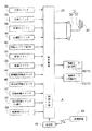
【図4】制御構成を示すブロック図
【図5】フローチャート
【図6】伸縮駆動機構の構成を示す(イ)要部側面図と(ロ)底面図
【図7】横送りスクリューコンベアの収縮状態を示す縦断側面図
【図8】横送りスクリューコンベアの伸長状態を示す縦断側面図
【図9】横送りスクリューコンベアの縦断正面図
【図10】別実施形態の制御構成を示すブロック図
【図11】誘導装置の別実施形態の平面図
【図12】伸縮駆動機構における回転センサの第2取付け構造を示す(イ)要部側面図と(ロ)底面図
【図13】同、第3別取付け構造を示す(イ)要部側面図と(ロ)底面図
【図14】伸縮限界スイッチの第2操作構造を示す(イ)要部側面図と(ロ)底面図
【符号の説明】
8 縦送りコンベア
9 横送りコンベア
10 起伏駆動機構
11 旋回駆動機構
12 伸縮駆動機構
A 制御手段
B 制御手段
P 格納位置
X 横軸芯
Y 縦軸芯[0001]
TECHNICAL FIELD OF THE INVENTION
The present invention provides a horizontal feed conveyor on the upper side of a vertical feed conveyor, which can be swung up and down around a horizontal axis by the operation of an up / down drive mechanism, and can be swiveled about the vertical axis by an operation of a swivel drive mechanism. The present invention also relates to a combine grain discharging device configured so that the horizontal feed conveyor can be expanded and contracted in the feed direction by operating a telescopic drive mechanism.
[0002]
[Prior art]
As the grain discharging device of the combine as described above, for example, as disclosed in JP-A-2-120134 and JP-A-2-195820, the above-described configuration allows the grain collecting point (for example, The grain discharge port provided at the tip of the horizontal feed screw conveyor with respect to the truck bed can be easily aligned in the near and far directions simply by operating the horizontal feed screw conveyor without moving the machine. In addition, even if the separation distance between the aircraft and the grain collection point becomes longer due to the presence of relatively high ridges or ridges and water between the field and the grain collection point, By extending the lateral feed screw conveyor so that its tip protrudes largely outside the machine body, it is possible to discharge the kernel from the field to the kernel collecting point. There are things you have.
[0003]
[Problems to be solved by the invention]
Conventionally, in the grain discharge devices of these combiners, in moving the horizontal feed screw conveyor to the grain collection point, the horizontal feed screw conveyor at the storage position is raised, then turned, and then extended and laterally fed. The screw conveyor has been moved to the desired grain collection point.
[0004]
By the way, in these grain discharge devices of the combine, the operating speed of the cylinder for raising and lowering the horizontal feed screw conveyor, or the turning motor for rotating the horizontal feed screw conveyor, and the cylinder for extending the horizontal feed screw conveyor are stopped. There is a limit due to the shock at the time and the like, and it is not possible to move the traverse screw conveyor to the grain collecting point too quickly.
[0005]
SUMMARY OF THE INVENTION It is an object of the present invention to reduce the time required for discharging a grain by promptly moving a horizontal feed screw conveyor to a grain collection point.
[0006]
[Means for Solving the Problems]
According to the first aspect of the present invention, a horizontal feed conveyor is provided on an upper part of a vertical feed conveyor so as to be able to swing up and down around a horizontal axis by an operation of an up-down drive mechanism, and to rotate around a vertical axis by an operation of a turning drive mechanism. The horizontal feed conveyor is equipped with a first conveyor section connected to the vertical feed conveyor and a second conveyor section connected to the first conveyor section. A combine grain discharging device configured to slide a second conveyor portion with respect to a first conveyor portion by operation of a drive mechanism so as to be expandable and contractible in a feed direction thereof, wherein a lateral feed at a storage position is provided. Given a grain discharge command to the conveyor, the maximum extended state where the transverse feed conveyor while moving toward the discharge position, grain transport path of the first conveyor unit a second conveyor unit of the transverse feed conveyor is most extended Remote it is equipped with a controller for controlling the operation of the telescopic drive mechanism so that the short set amount extended state.
[0007]
[Action]
According to the first aspect of the present invention, when the traversing conveyor is moved to the grain collecting point, when a raising command as a grain discharging command is given to the traversing conveyor at the storage position, the raising operation is performed. By operation of the telescopic drive mechanism based on the command, the ascending and elongating are performed at the same time, and the moving time of the traverse conveyor to the grain collecting point can be shortened as compared with the case where the ascending and elongating are performed separately. Moreover, since the elongation is performed by the set amount shorter than the maximum elongation state, as in the case of the maximum elongation, it becomes too long to make it difficult to turn, and there is no waste of shortening at the grain collection point.
〔effect〕
According to the above configuration, it is possible to shorten the moving time of the lateral feed conveyor to the grain collecting point and shorten the grain discharging work time.
[0008]
BEST MODE FOR CARRYING OUT THE INVENTION
Hereinafter, embodiments of the present invention will be described with reference to the drawings.
[0009]
FIG. 1 shows an overall side view of a self-contained combine, and FIG. 2 shows an entire plan view of the self-contained combine. The combine includes a
[0010]
The
[0011]
As shown in FIGS. 3 and 4, the undulating
[0012]
As shown in FIGS. 7 and 8, the
[0013]
As shown in FIG. 9, the
[0014]
As shown in FIG. 8, the belt conveyer
[0015]
A
[0016]
As shown in FIGS. 1 and 2, the traveling
[0017]
As shown in FIGS. 3 and 4, the
[0018]
The control operation of the
[0019]
As shown in FIGS. 2 and 4, an electromagnetically induced wave output from a guiding
[0020]
During the control operation based on the command from the
[0021]
When the
[0022]
According to the above configuration, when the
[0023]
[Another embodiment]
In the above-described embodiment, as a means for shortening the moving time of the horizontal
[0024]
In addition, as a means for shortening the moving time of the horizontal feed screw conveyor to the grain collecting point, during the harvesting operation, the horizontal feed screw conveyor stored in the storage position P is contracted and stored slightly longer than the maximum contracted state. By doing so, it is possible to shorten the time required for the lateral feed screw conveyor to move to the grain collection point, as compared to the case where the horizontal feed screw conveyor is operated from the maximum contracted state when moving to the next grain collection point. May be.
In this case, as shown in FIG. 10, when the
When the
In the case of this embodiment, when the machine is stored in a garage or barn, the horizontal
(Note that components having the same functions as those of the above-described embodiment are denoted by the same reference numerals and symbols as those of the embodiment.)
[0025]
Further, in the above embodiment, the present invention is applied to a self-removing type combine. However, the present invention applies to all culms as long as they are provided with a laterally feeding
[0026]
As shown in FIG. 11, a guiding
[0027]
In the above embodiment, the
[Brief description of the drawings]
FIG. 1 is an overall side view of a self-removing combine. FIG. 2 is an overall plan view of a self-removing combine showing a grain discharging state. FIG. 3 is a grain discharging device showing a configuration of an up-down driving mechanism and a swing driving mechanism. FIG. 4 is a block diagram showing a control configuration. FIG. 5 is a flow chart. FIG. 6 is a side view and (b) a bottom view showing a configuration of a telescopic drive mechanism. FIG. 8 is a vertical side view showing a contracted state of a conveyor. FIG. 8 is a vertical side view showing an extended state of a horizontal feed screw conveyor. FIG. 9 is a vertical front view of a horizontal feed screw conveyor. FIG. 10 is a block diagram showing a control configuration of another embodiment. FIG. 11 is a plan view of another embodiment of the guiding device. FIG. 12 is a side view of a main part and a bottom view of a second mounting structure of a rotation sensor in a telescopic drive mechanism. (A) Side view of main part showing third attachment structure And (b) bottom view Figure 14 shows a second operation structure of the stretch limit switch (a) partial side view and (b) bottom view EXPLANATION OF REFERENCE NUMERALS
Claims (1)
格納位置にある横送りコンベア(9)に穀粒排出位置への作動指令を与えると、前記横送りコンベア(9)が排出位置に向かって移動中に、横送りコンベア(9)の第一コンベア部(9A)と第二コンベア部(9B)との穀粒移送経路が最も延びた最大伸長状態よりも短い設定量伸長状態となるように前記伸縮駆動機構(12)の作動を制御する制御手段(A)を装備してあるコンバインの穀粒排出装置。On the upper part of the vertical feed conveyor (8), a horizontal feed conveyor (9) is rotatable up and down around a horizontal axis by the operation of an up / down drive mechanism (10) and vertically by the operation of a turning drive mechanism (11). In addition to being equipped so as to be able to swing and swing around the axis, the horizontal feed conveyor (9) is connected to a first conveyor portion (9A) connected to the vertical feed conveyor (8) and the first conveyor portion (9A). 9A), the second conveyor section (9B) is slid relative to the first conveyor section (9A) by the operation of the telescopic drive mechanism (12). Combine grain discharging device configured to be stretchable in the feeding direction,
When an operation command to the grain discharge position is given to the transverse conveyor (9) at the storage position, the first conveyor of the transverse conveyor (9) is moved while the transverse conveyor (9) is moving toward the discharge position. Control means for controlling the operation of the telescopic drive mechanism (12) such that the grain transfer path between the section (9A) and the second conveyor section (9B) is in a set amount extension state shorter than the maximum extension state in which the grain is most extended. Combine grain discharging device equipped with (A).
Priority Applications (1)
| Application Number | Priority Date | Filing Date | Title |
|---|---|---|---|
| JP27312296A JP3592002B2 (en) | 1996-10-16 | 1996-10-16 | Combine grain discharger |
Applications Claiming Priority (1)
| Application Number | Priority Date | Filing Date | Title |
|---|---|---|---|
| JP27312296A JP3592002B2 (en) | 1996-10-16 | 1996-10-16 | Combine grain discharger |
Publications (2)
| Publication Number | Publication Date |
|---|---|
| JPH10117576A JPH10117576A (en) | 1998-05-12 |
| JP3592002B2 true JP3592002B2 (en) | 2004-11-24 |
Family
ID=17523443
Family Applications (1)
| Application Number | Title | Priority Date | Filing Date |
|---|---|---|---|
| JP27312296A Expired - Fee Related JP3592002B2 (en) | 1996-10-16 | 1996-10-16 | Combine grain discharger |
Country Status (1)
| Country | Link |
|---|---|
| JP (1) | JP3592002B2 (en) |
Families Citing this family (1)
| Publication number | Priority date | Publication date | Assignee | Title |
|---|---|---|---|---|
| JP4714966B2 (en) * | 2000-07-10 | 2011-07-06 | 井関農機株式会社 | Combine harvester |
-
1996
- 1996-10-16 JP JP27312296A patent/JP3592002B2/en not_active Expired - Fee Related
Also Published As
| Publication number | Publication date |
|---|---|
| JPH10117576A (en) | 1998-05-12 |
Similar Documents
| Publication | Publication Date | Title |
|---|---|---|
| JP3592002B2 (en) | Combine grain discharger | |
| JPS6112193Y2 (en) | ||
| JP3874695B2 (en) | Operation device of auger for grain discharge in combine | |
| JPH09103184A (en) | Combine grain discharger | |
| JP3746320B2 (en) | Combine grain auger automatic operating device | |
| JP3596990B2 (en) | Grain discharging equipment in combine harvesters | |
| JP3849303B2 (en) | Combine grain auger control device | |
| JP4533174B2 (en) | Combine | |
| JP2006238897A (en) | Operation device of auger for grain discharge in combine | |
| JP3757593B2 (en) | Combine grain unloading device | |
| JP2688187B2 (en) | Auger operating device for grain discharge in combine harvesters | |
| JP2995746B2 (en) | Grain discharging device | |
| JP3302613B2 (en) | Combine unloader | |
| JP5060140B2 (en) | Combine | |
| JP2017012060A (en) | Grain discharger | |
| JP4257450B2 (en) | Combine | |
| JP2000300052A (en) | Telescopic auger equipment of combine harvester | |
| JPH10201355A (en) | Radio controller for discharging auger | |
| JP2664069B2 (en) | Auger operating device for grain discharge in combine harvesters | |
| JP2005065623A (en) | Grain discharger | |
| EP0945295B1 (en) | Automatic device for moving covering sheets for vehicles | |
| JPH03130011A (en) | Operating device for auger for grain discharge in a combine harvester | |
| JP3184936B2 (en) | Combine grain discharger | |
| JP2001238527A (en) | Operation device of auger for unloading grain in combine harvester | |
| JP2013230108A (en) | Grain discharge device of combine harvester |
Legal Events
| Date | Code | Title | Description |
|---|---|---|---|
| A977 | Report on retrieval |
Free format text: JAPANESE INTERMEDIATE CODE: A971007 Effective date: 20040326 |
|
| A131 | Notification of reasons for refusal |
Free format text: JAPANESE INTERMEDIATE CODE: A131 Effective date: 20040506 |
|
| A521 | Written amendment |
Free format text: JAPANESE INTERMEDIATE CODE: A523 Effective date: 20040625 |
|
| TRDD | Decision of grant or rejection written | ||
| A01 | Written decision to grant a patent or to grant a registration (utility model) |
Free format text: JAPANESE INTERMEDIATE CODE: A01 Effective date: 20040805 |
|
| A61 | First payment of annual fees (during grant procedure) |
Free format text: JAPANESE INTERMEDIATE CODE: A61 Effective date: 20040824 |
|
| R150 | Certificate of patent or registration of utility model |
Free format text: JAPANESE INTERMEDIATE CODE: R150 |
|
| LAPS | Cancellation because of no payment of annual fees |