JP3589397B2 - Flow pulse generating method and apparatus, and electronic gas meter - Google Patents
Flow pulse generating method and apparatus, and electronic gas meter Download PDFInfo
- Publication number
- JP3589397B2 JP3589397B2 JP19889199A JP19889199A JP3589397B2 JP 3589397 B2 JP3589397 B2 JP 3589397B2 JP 19889199 A JP19889199 A JP 19889199A JP 19889199 A JP19889199 A JP 19889199A JP 3589397 B2 JP3589397 B2 JP 3589397B2
- Authority
- JP
- Japan
- Prior art keywords
- volume
- passing volume
- value
- passing
- flow
- Prior art date
- Legal status (The legal status is an assumption and is not a legal conclusion. Google has not performed a legal analysis and makes no representation as to the accuracy of the status listed.)
- Expired - Fee Related
Links
- 238000000034 method Methods 0.000 title claims description 41
- 230000010354 integration Effects 0.000 claims description 43
- 238000004364 calculation method Methods 0.000 claims description 20
- 230000005856 abnormality Effects 0.000 claims description 6
- 230000001186 cumulative effect Effects 0.000 claims 1
- 238000005070 sampling Methods 0.000 description 47
- 230000008569 process Effects 0.000 description 30
- 238000012545 processing Methods 0.000 description 22
- 238000005259 measurement Methods 0.000 description 12
- 230000006870 function Effects 0.000 description 9
- 230000005540 biological transmission Effects 0.000 description 8
- 238000004904 shortening Methods 0.000 description 8
- 238000004891 communication Methods 0.000 description 6
- 238000010586 diagram Methods 0.000 description 6
- 230000033001 locomotion Effects 0.000 description 3
- 230000007246 mechanism Effects 0.000 description 3
- 230000004044 response Effects 0.000 description 3
- 235000014676 Phragmites communis Nutrition 0.000 description 2
- 238000012937 correction Methods 0.000 description 2
- 238000013500 data storage Methods 0.000 description 2
- 238000011161 development Methods 0.000 description 2
- 230000000630 rising effect Effects 0.000 description 2
- 238000005303 weighing Methods 0.000 description 2
- 230000002159 abnormal effect Effects 0.000 description 1
- 238000002485 combustion reaction Methods 0.000 description 1
- 230000008878 coupling Effects 0.000 description 1
- 238000010168 coupling process Methods 0.000 description 1
- 238000005859 coupling reaction Methods 0.000 description 1
- 230000007423 decrease Effects 0.000 description 1
- 230000000694 effects Effects 0.000 description 1
- 238000009434 installation Methods 0.000 description 1
- 239000012528 membrane Substances 0.000 description 1
- 230000010355 oscillation Effects 0.000 description 1
- 230000003068 static effect Effects 0.000 description 1
- 238000011144 upstream manufacturing Methods 0.000 description 1
Images


Landscapes
- Measuring Volume Flow (AREA)
- Details Of Flowmeters (AREA)
Description
【0001】
【発明の属する技術分野】
本発明は、ガスの流速に応じて変化する物理量を間欠的に、すなわち、サンプリング周期にて計測し、この計測した物理量によってガス流速を求め、この流速と流路の断面積とによって瞬時流量を求め、この瞬時流量に間欠時間を乗じて求めた通過体積に応じてガスの単位通過体積に対応した流量パルスを発生する流量パルス発生方法及び装置に関するものである。
本発明は更に、流量パルス発生装置において計測した通過体積を積算して表示する計量表示部と流量パルス発生装置の発生する流量パルスによってガス流の異常を検出する保安論理部とを内蔵した電子式ガスメータに関するものである。
【0002】
【従来の技術】
従来の膜式のガスメータでは、ダイヤフラムからなる隔膜によって仕切られた2つの部屋と、この2つの部屋の各々をガス入口部及びガス出口部に交互に接続する滑弁からなる切換弁と、隔膜と切換弁を連結して隔膜の移動を切換弁に伝達して切換弁を駆動する連結機構とを備えた構造を有している。このガスメータでは、ガスメータの下流側においてガス消費などがあってガス出口部のガス圧が低下すると、ガス入口部とガス出口部との間に差圧が生じ、ガス入口部につながっている一方の部屋にガスが流入し、このガスの流入により隔膜が移動してガス出口部につながっている他方の部屋のガスが排出される。一方の部屋に十分なガスが流入し、他方の部屋のガスが十分に排出される程に隔膜が移動すると、この隔膜の移動が連結機構を介して切換弁に伝達されて切換弁を駆動し、それまでガス入口部に接続されていた一方の部屋をガス出口部に接続し、ガス出口部に接続されていた他方の部屋をガス入口部に接続するようになる。
【0003】
よって、以後他方の部屋にガスが流入し、一方の部屋のガスが排出されるようになる。また、連結機構の途中から得た動力によって駆動され、隔膜が一往復して所定ガス量を排出したことに応じて1回転するNS極の着磁されたマグネットが取付られており、このマグネットの1回転によってリードスイッチがオン、オフして流量パルスを発生するようになっている。すなわち、隔膜の往復動に連動して回転するマグネットとリードスイッチによって流量センサが構成されている。また、ガスメータには、上述した流量センサからの流量パルスに基づいてガス流を監視してその異常を検出し、ガス事故を防止する各種の保安機能を実行する保安論理部が内蔵されている。
【0004】
ところで、上述の流量センサがガス流量を検出して発生する流量パルスは、隔膜が一往復して例えば0.7Lの単位計量体積を計量する毎に発生される2つのパルスからなっており、この流量パルスの周期はガス流量が大きくなると短くなり、小さくなると長くなる。この流量パルスを利用する保安論理部は、流量パルスの各パルスが入力される毎に前回パルスからの周期を計測処理してガス流量を求め、このガス流量に基づいて論理処理を行って保安のための機能を果たすようになっている。
【0005】
最近、上述した膜式のガスメータは機械的な動作を伴うため、構造が複雑でかつ小型化に制限があるほか、寿命の点でも問題があるので、膜式のガスメータに代えて完全に電子化した各種の電子ガスメータが提案されている。これらに共通していることは、ガス流の速度によって変化する物理量を計測することによってガス流速を求め、この求めた流速と流路の断面積とによって瞬時流量を求め、この瞬時流量を積分して通過体積を計算し、この通過体積を積算して積算流量を求めるようにしている。例えば、超音波式流量センサでは、ガス流の速度によって超音波の伝達時間が変化することを利用し、ガス流中に超音波を間欠的に発射してその到達時間を計測することによって、ガス流速を計測し、この計測した流速に流路の面積を乗じて瞬時流量を求め、この瞬時流量に間欠時間を乗じて通過流量を算出するようになっている。
【0006】
したがって、ガスメータの積算流量を求める機能だけを得ようとするのであれば、上述したように、流速と流路の断面積とによって瞬時流量を求め、この瞬時流量を積分して積算流量を求めるようにすればよいが、開発の手間や安全規格の再取得などの観点から、保安論理部に従来からのものを利用しようとした場合には、流量センサの出力によって計測した物理量に基づいて通過体積を求める流量計測部に、通過体積に応じた周期の流量パルスを出力させる機能を付加する必要がある。
【0007】
因みに、通過流量が100(m3 /h)で40(L/パルス)の流量パルスを出力する場合には、流量パルスの信号周波数は0.694Hz(周期は1.44秒)となるが、流量パルスを精度良く出力するためには、超音波式センサでは超音波を発射して流速を計測する周期、すなわち、サンプリング周期を1.44秒以下にしなければならない。これは、ガス流速或いはガス流量を反映した周期の流量パルスを出力しようとしたとき、その出力周期がくる前に計測を終わっていなければならないからである。このため、100(m3 /h)以上の通過流量のものを考えたときには、流量計測部におけるサンプリング周期が限りなく短くなっていく。
【0008】
【発明が解決しようとする課題】
上述したように、流量パルスを発生する毎にサンプリングを行うようにしたものにおいては、短い周期の流量パルスを発生する場合、サンプリング周期をそれに伴って短くしておくことが必要となる。例えば、超音波式の流量センサでは、サンプリング毎に超音波を発射して信号処理を行わなければならず、電力消費が大きくなり、電源として電池を使用しているが、電池交換をできるだけ避けたいガスメータに上述のような流量パルス発生方法及び装置を適用することが難しくなる。
【0009】
よって、本発明は、上述した点に鑑み、サンプリング周期を短くすることなく、ガスの通過体積に応じた周期のガスの単位通過体積に対応した流量パルスを発生できるようにした流量パルス発生方法及び装置を提供することを課題としている。
【0010】
本発明はまた、サンプリング周期を短くすることなく、ガスの通過体積に応じた周期のガスの単位通過体積に対応した流量パルスを発生できるようにした流量パルス発生装置と、該流量パルス発生装置の発生する流量パルスを利用する保安論理部とを有する電子式ガスメータを提供することを課題としている。
【0011】
【課題を解決するための手段】
上記課題を解決するため成された請求項1記載の発明は、通過体積を一定周期で間欠的に算出し、通過体積を算出する毎に、該算出した通過体積の1/N値を算出し、該算出した1/N値をそれ以前の積算値に順次積算し、該積算値が単位通過体積の1/2以上となる毎にその積算回数を求めるとともに積算値から単位通過体積の1/2の値を減算することを前記1/N値をN回積算するまで繰り返して求めた前記積算回数に前記一定周期の1/Nを乗じて出力を反転するタイミングを事前に決定し、その後、次の通過体積の算出までに、前記決定したタイミングで出力を反転して前記通過体積に応じた周期のガスの単位通過体積に対応した流量パルスを発生することを特徴とする流量パルス発生方法に存する。
【0012】
請求項1記載の流量パルス発生方法の手順によれば、一定周期で間欠的に算出した通過体積の1/N値を、その算出毎に、算出した通過体積の1/N値を算出し、該算出した1/N値をそれ以前の積算値に順次積算し、該積算値が単位通過体積の1/2以上となる毎にその積算回数を求めるとともに積算値から単位通過体積の1/2の値を減算することを1/N値をN回積算するまで繰り返す。積算回数に一定周期の1/Nを乗じて決定したタイミングで出力を反転して通過体積に応じた周期のガスの単位通過体積に対応した流量パルスを発生する。
【0013】
以上により、算出した通過体積が小さいときには1/N値が小さくなって、その積算値が単位通過体積の1/2以上となることがなく、次の通過体積が算出されるまでに出力を反転するタイミングが決定されることがない。また、通過体積が大きいときには1/N値が大きくなって、その積算値が単位通過体積の1/2以上となることが複数回となって、次の通過体積が算出されるまで出力を反転するタイミングが複数決定されることになる。よって、積算した通過体積が小さいときすなわち流量が小さいときには、1回間欠的に算出した通過体積によっても流量パルスを出力しなくなり、また積算した通過体積が大きいときすなわち流量が大きいときには、1回間欠的に算出した通過体積でも単位通過体積の1/2毎に反転する複数の流量パルスを出力するようになるので、通過体積が大きい場合にも、間欠的な通過体積の算出周期を短くすることなく、すなわち、サンプリング周期を短くすることなく、通過体積に応じた周期のガスの単位通過体積に対応した流量パルスを発生できる。また、流量パルスは単位通過体積の1/2すなわち半分の積算値毎に反転するので、流量パルスの立ち上がり又は立ち下がりから立ち下がり又は立ち上がりによって、単位通過体積を検出することができる。
【0014】
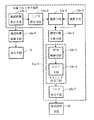
上記課題を解決するため成された請求項2記載の発明は、図1の基本構成図に示すように、通過体積を一定周期で間欠的に算出する通過体積算出手段14a−1と、該通過体積算手段によって通過体積が算出される毎に、前記通過体積の1/N値を算出する1/N算出手段14a−2と、前記1/N値を順次積算する積算手段14a−3と、前記1/N値をN回積算するまで、前記積算手段による積算値が単位通過体積の1/2以上となるまでの積算回数を計数することを繰り返す積算回数計数手段14a−4と、前記1/N値をN回積算するまで、前記積算値が単位通過体積の2分の1となる毎に前記積算値から単位通過体積の1/2の値を減算することを繰り返す減算手段14a−5と、前記積算回数に前記一定周期の1/Nを乗じ、前記通過体積算出手段が通過体積を次に算出するまでの出力を反転するタイミングを決定するタイミング決定手段14a−6と、該タイミング決定手段によって決定したタイミングで出力を反転して前記通過体積に応じた周期の単位通過体積に対応する流量パルスを発生するパルス発生手段14a−7とを備えることを特徴とする流量パルス発生装置に存する。
【0015】
請求項2記載の流量パルス発生装置によれば、通過体積算出手段14a−1が一定周期で間欠的に通過体積を算出し、その算出毎に、1/N算出手段14a−2が通過体積の1/N値を算出する。積算手段14a−3が1/N値を順次積算し、1/N値をN回積算するまで、積算手段による積算値が単位通過体積の1/2以上となるまでの積算回数を積算回数計数手段14a−4が計数することを繰り返す。また、1/N値をN回積算するまで、積算値が単位通過体積の2分の1となる毎に減算手段14a−5が積算値から単位通過体積の1/2の値を減算することを繰り返す。タイミング決定手段14a−6が積算回数に一定周期の1/Nを乗じ、通過体積算出手段が通過体積を次に算出するまでの出力を反転するタイミングを決定する。パルス発生手段14a−7がタイミング決定手段によって決定したタイミングで出力を反転して前記通過体積に応じた周期の単位通過体積に対応する流量パルスを発生する。
【0016】
以上により、算出した通過体積が小さいときには1/N値が小さくなって、その積算値が単位通過体積の1/2以上となることがなく、次の通過体積が算出されるまでに出力を反転するタイミングが決定されることがない。また、通過体積が大きいときには1/N値が大きくなって、その積算値が単位通過体積の1/2以上となることが複数回となって、次の通過体積が算出されるまで出力を反転するタイミングが複数決定されることになる。よって、積算した通過体積が小さいときすなわち流量が小さいときには、1回間欠的に算出した通過体積によっても流量パルスを出力しなくなり、また積算した通過体積が大きいときすなわち流量が大きいときには、1回間欠的に算出した通過体積でも単位通過体積の1/2毎に反転する複数の流量パルスを出力するようになるので、通過体積が大きい場合にも、間欠的な通過体積の算出周期を短くすることなく、すなわち、サンプリング周期を短くすることなく、通過体積に応じた周期のガスの単位通過体積に対応した流量パルスを発生できる。また、流量パルスは単位通過体積の1/2すなわち半分の積算値毎に反転するので、流量パルスの立ち上がり又は立ち下がりから立ち下がり又は立ち上がりによって、単位通過体積を検出することができる。
【0017】
請求項3記載の発明は、請求項2記載の流量パルス発生装置において、前記タイミング決定手段は、前記積算回数に前記一定周期の1/Nを乗じて求めた時間を格納する時間格納手段14c−1と、該時間格納手段に格納された時間を順次読み出し計時するタイマ手段14c−2とを有し、該タイマ手段が前記読み出した時間を計時した時点を、前記通過体積算出手段が通過体積を次に算出するまでの出力を反転するタイミングとして決定することを特徴とする流量パルス発生装置に存する。
【0018】
請求項3記載の流量パルス発生装置によれば、時間格納手段14c−1が積算回数に一定周期の1/Nを乗じて求めた時間を格納し、タイマ手段14c−2が格納されている時間を順次読み出し計時し、タイマ手段が読み出した時間を計時した時点を、通過体積算出手段が通過体積を次に算出するまでの出力を反転するタイミングとして決定するので、通過体積を算出した直前に積算値があるときの積算回数は前の積算値を反映し1/N値を積算する回数が小さく、その後の積算回数は大きくなる。よって、時間格納手段14c−1には、積算回数に一定周期の1/Nを乗じて求めた複数の時間が格納されることがあるが、タイマ手段14c−2が格納された時間を順次読出して計時し、ガスの通過体積に応じた周期のガスの単位通過体積に対応した流量パルスに変換して出力することができる。
【0019】
請求項4記載の発明は、請求項2又は3記載の流量パルス発生装置と、該流量パルス発生装置の前記通過体積算出手段によって求めた通過体積を積算する通過体積積算手段14a−8と、該通過体積積算手段により積算した通過体積を表示する表示手段15と、前記流量パルス発生装置の発生する流量パルスによってガス流の異常を検出する保安論理手段20とを備えることを特徴とする電子式ガスメータに存する。
【0020】
請求項4記載の電子式ガスメータによれば、流量パルス発生装置が通過体積に応じた周期の流量パルスを発生するので、保安論理手段20として流量パルスの各パルスの周期によってガス流の異常を検出するものを使用することができる。
【0021】
【発明の実施の形態】
以下、本発明の実施の形態を図面に基づいて説明する。
図2は本発明による流量パルス発生方法を実施する装置及び流量計測装置を組み込んだ電子式ガスメータ1を示している。図示の電子式ガスメータ1は流量計測部100と保安論理部20とを有する。
【0022】
流量計測部100は、ガスの流速に応じて変化する物理量を間欠的に、すなわち、サンプリング周期にて計測し、この計測した物理量によってガス流速を求め、この流速と流路の断面積とによって瞬時流量を求め、この瞬時流量に間欠時間を乗じて通過体積を求めると共に、この求めた通過体積によりガスの単位通過体積に対応した流量パルスを発生し、この流量パルスを保安論理部20に供給するようになっている。保安論理部20は、流量計測部100からの流量パルスによってガス流の異常を検出する。
【0023】
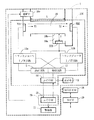
流量計測部100として、図3に示す超音波式のものを例にして以下説明する。超音波式の流量計測部100は、ガスを流すガスメータ中の流路としてのガス流路10内にガス流方向において距離Lだけ離され互いに対向して配置された超音波周波数で作動する例えば圧電式振動子からなる2つの音響トランスジューサTD1及びTD2と、ガス流路10に連通した空所10a内に距離lだけ離れた管壁10bに対向して配置された音響トランスジューサTD3とを有する。ガス流路10には、両音響トランスジューサTD1、TD2の上流側に弁閉によってガス流路10を遮断する遮断弁10cが設けられている。
【0024】
各トランスジューサTD1及びTD2、TD3はトランスジューサインタフェース(I/F)回路11a及び11bをそれぞれ介して送信回路12及び受信回路13に接続されている。送信回路12は、マイクロコンピュータ(μCOM)14の制御の下で、トランスジューサTD1、TD2の一方を駆動して超音波信号を発生させる信号をパルスバーストの形で送信し、このための発振回路(図示せず)を内蔵している。受信回路13は、ガス流路10を通過した超音波信号を受信した他方のトランスジューサTD1、TD2からの信号を入力して超音波信号を処理する前置増幅器(図示せず)を内蔵している。トランスジューサTD3については、トランスジューサTD1及びTD2に対するとは別のタイミングでμCOM14が送信回路12と受信回路13を制御し、トランスジューサTD3を駆動して超音波信号を発生させるように送信回路12を制御するとともに、同じトランスジューサTD3が管壁10bから反射されてくる超音波信号を受信して発生する信号を入力させるように受信回路13を制御する。
【0025】
μCOM14はまた、MODEM(変復調回路)18、NCU(網制御ユニット)19を介して公衆通信網である電話回線に接続され、遠隔の管理センタとの間で通信を行う通信処理も行うようになっている。
【0026】
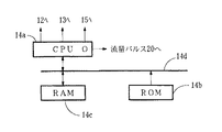
なお、μCOM14は、図4に示すように、プログラムに従って各種の処理を行う中央処理ユニット(CPU)14a、CPU14aが行う処理のプログラムなどを格納した読み出し専用のメモリであるROM14b、CPU14aでの各種の処理過程で利用するワークエリア、各種データを格納するデータ格納エリアなどを有する読み出し書き込み自在のメモリであるRAM14cなどを内蔵し、これらがバスライン14dによって相互接続されている。
【0027】
μCOM14内のCPU14aは、送信回路12から信号を供給するトランスジューサと受信回路13で超音波信号を受信するトランスジューサとを交互に切り替える制御を行うと共に、2つのトランスジューサ間で交互に送受信した超音波信号の伝搬時間を測ってガス流路10内を流れているガスの流速を間欠的に求めるための流速算出処理の他に、この算出した流速とガス流路10の断面積とに基づいて瞬時流量を求める流量算出処理、算出した瞬間流量に間欠時間を乗じて通過体積を算出する通過体積算出処理、算出した通過体積を積算して積算通過体積を求める通過体積積算処理、この通過体積積算処理によって求めた通過体積積算値を表示器15に表示させる表示処理を行う。これらはガスメータとしての本来の機能にかかわるものである。この他、μCOM14内のCPU14aは、算出した通過体積を利用してガスの単位通過体積に対応した流量パルスを出力ポートOに発生する流量パルス発生処理を行うようになっている。
【0028】
上述したガスメータとして働くための流量計測の原理を以下に説明する。μCOM14の内蔵するCPU14aは、送信回路12にトリガ信号を出力してパルスバースト信号を発生させ、これを一方のトランスジューサTD1、TD2に供給させて、この一方のトランスジューサに超音波信号を発生させる。また、一方のトランスジューサから送信された超音波信号を受信する他方のトランスジューサからの信号を受信回路13に受信させ、これに応じて受信回路13が発生する信号を取り込む。その後、μCOM14の内蔵するCPU14aは、超音波信号を発生するトランスジューサと超音波信号を受信するトランスジューサを逆にして同じ動作をもう一度繰り返す制御を行う。そして、μCOM14のCPU14aは、送信回路12にトリガ信号を出力して一方のトランスジューサに超音波信号を発生させて、この超音波信号を受信する他方のトランスジューサが発生する信号を受信回路13を介して取り込むまでの時間T1、T2をそれぞれ測り、この測った時間T1、T2からガス流の流速を後述のようにして求める。
【0029】
また、μCOM14のCPU14aは、トランスジューサTD1、TD2についての制御とは別のタイミングで、トランスジューサTD3についての制御を行い、送信回路12にトリガ信号を出力してパルスバースト信号を発生させ、これをトランスジューサTD3に印加させて、このトランスジューサTD3に超音波信号を発生させる。また、トランスジューサTD3から送信され管壁10bで反射された超音波信号を受信する同じトランスジューサTD3からの信号を受信回路13に受信させ、これに応じて受信回路13が発生する信号を取り込む。そして、CPU14aは、送信回路12にトリガ信号を出力してトランスジューサTD3に超音波信号を発生させて、この超音波信号の反射の第1波と第2波を受信する同じトランスジューサTD3が発生する信号を受信回路13を介して取り込むまでの時間Tr1、Tr2をそれぞれ測り、この測った時間Tr1、Tr2からガス流路10内と同じ温度、圧力、ガス種であるが、ガス流のない雰囲気における音速を後述のようにして求める。
【0030】
今、静止ガス中での音の伝搬速度(音速)をc、ガス流の流速をvとすると、ガス流の順方向の超音波信号の伝搬速度は(c+v)となる。トランスジューサTD1及びTD2間の距離をLとすると、トランスジューサTD1からの超音波信号がガス流と同じ方向に進んでトランスジューサTD2に到達する時間T1と、トランスジューサTD2からの超音波信号がガス流と逆方向に進んでトランスジューサTD1に到達する時間T2とは、
T1=L/(c+v) (1)
T2=L/(c−v) (2)
となる。(1)、(2)式より
v=(L/2)・(1/T1−1/T2)
=(L/2)・((T2−T1)/(T2・T1)) (3)
となり、Lが既知であるときには、T1及びT2を計測することによって流速vを求めることができる。
【0031】
なお、T2・T1=L/(c+v)・(c−v)=L/(c2 −v2 )であり、流速vは音速cに比べて極めて小さな数値であるので、式中のv2 はc2 に比べて極めて小さく無視でき、T2・T1=L/c2
とすることができる。そして、上式(3)は最終的には、

となる。
【0032】
流速vが求められたときには、瞬時流量Qiはガス流路10の既知の断面積をS、物の構造その他によって変化する補正係数をαとすると、
K=α・S・k (6)
とする。なお、Kは上述の説明から明らかなように、音速、ガス温度、ガス圧力など多くの要素を含んだ補正のための係数である。
【0033】
なお、式(6)中の静止ガス中の音速cについては、図3に示したように、ガス流路10に連通しているが、ガス流路10中のガス流に影響されない静止ガスの空所10a中において、第3の音響トランスジューサTD3から発した超音波信号が管壁10bの内表面で反射してトランスジューサに戻ってくるまでの時間を計測し、この時間によってトランスジューサTD3から管壁10bまでの往復距離2lを割ることによって求めることができるので、この計測を適宜行って求めた音速cを用いるようにすればよい。
【0034】
従って、瞬時流量Qiを求める毎に、すなわち、サンプリングする毎に、この流量Qiに前回求めた(サンプリングした)時点からの経過時間(サンプリング間隔の時間)を乗じることによって通過体積Qtが求まり、これを積算することによって、積算した積算体積Qs、すなわち、ガス供給量(ガス使用量)を求めることができるようになる。そして、この積算通過体積Qsを表示器15に表示させることによって電子式ガスメータを構成することができる。
【0035】
次に、算出した通過体積を利用してガスの単位通過体積に対応した流量パルスをCPU14aが出力ポートOに出力する処理を以下説明する。
【0036】
流量計測処理において、CPU14aが一定周期のサンプリング時間の経過毎にサンプリングして計測した物理量であるガスの流速に流路の断面積を乗じて求めた瞬時流量にサンプリング間隔の時間を乗じる計算を行うことによって、サンプリング間隔の間に通過したガス体積を通過体積として算出する。この算出した通過体積を、RAM14cの所定エリアに形成した通過体積格納手段に一時格納する。次に、通過体積格納手段に一時格納した通過体積をN分の1して1/N値を算出し、これをRAM14cの他の所定エリアに形成した1/N値格納手段に一時格納する。
【0037】
続いて、算出した1/N値を順次積算するが、それ以前にパルス出力すべき積算値がなければ、順次積算した1/N値が予め定められた単位通過流量の2分の1の値すなわち1/2以上になるときまでの積算回数を計数して求めるとともに積算値から単位通過流量の1/2の値を減算して積算値を0にし、この処理を1/N値をN回積算するまで繰り返す。また、それ以前にパルス出力すべき積算値があれば、その積算値に1/N値を順次積算し、順次積算した1/N値が予め定められた単位通過流量の2分の1の値すなわち1/2以上になるときまでの積算回数を求めるとともに積算値から単位通過流量の1/2の値を減算して積算値を0にし、この処理を1/N値をN回積算するまで繰り返す。なお、順次積算した1/N値が予め定められた単位通過流量の1/2以上になるときまでの積算回数が求まる毎に、これをRAM14cの他の所定エリアに形成した積算回数格納手段に一時格納し、その後の出力を反転するタイミングを決定するために利用する。
【0038】
その後、積算回数格納手段に格納した積算回数に、一定周期のサンプリング時間、すなわちサンプリング周期をN分の1して求めたサンプリング周期の1/Nをそれぞれ乗じて出力を反転するタイミングを決定する。このために、サンプリング周期の1/Nをそれぞれ乗じて求めた時間をRAM14cの他の所定エリアに形成した時間格納手段に一時格納し、時間格納手段に格納した時間を順次読み出し、この読み出した時間を、RAM14cの他の所定エリアに形成したタイマ手段により計時する。そして、タイマ手段が読み出した時間を計時した時点を、通過体積を次に算出するまでの出力を反転するタイミングとして決定する。
【0039】
以上により、一定周期のサンプリング後に算出した1/N値を順次積算して求めた積算値が単位通過流量の1/2以上になるときまでの積算回数を求めるとともに積算値から単位通過流量の1/2の値を減算して、この処理を1/N値をN回積算するまで繰り返し、積算回数に、サンプリング周期の1/Nをそれぞれ乗じて出力を反転するタイミングを決定し、通過体積の値が流量パルスを形成している単位通過体積1個以上に相当する値になっているときには、その大きさに応じた周期のパルスからなる流量パルスを出力することができるようになる。
【0040】
上述の流量パルス出力処理によって発生される流量パルスは、保安論理部20に入力される。保安論理部20は、図4の流量計測部10のμCOM14と同様に、図5に示すように、プログラムに従って各種の処理を行う中央処理ユニット(CPU)21a、CPU21aが行う処理のプログラムなどを格納した読み出し専用のメモリであるROM21b、CPU21aでの各種の処理過程で利用するワークエリア、各種データを格納するデータ格納エリアなどを有する読み出し書き込み自在のメモリであるRAM21cなどがバスライン21dによって相互接続されているμCOM21によって形成されている。
【0041】
保安論理部20を形成しているμCOM21内のCPU14aは、流量計測部10から入力する流量パルスを形成している各パルス毎に処理を行って、保安論理によって実行される機能の1つ、例えば合計流量遮断機能において、ガスメータの設置先の燃焼器具の合計ガス消費量が学習により自動設定された遮断値を越えた場合、元栓の誤開放やゴムホースの抜けなどによる大量のガス漏れと判断して遮断弁10cを弁閉しガスを遮断する。また、増加流量遮断機能において、ガスの流量が増大したとき、設置先の燃焼器具のうち、最大消費のガス器具に比べて異常に大きな流量の増加があった場合、元栓の誤開放やゴムホースの抜けなどによるガス漏れと判断して遮断弁10cを弁閉しガスを遮断するなどの保安動作を行わせる。また、保安動作によって何らかの警報を行う場合には警報部22の発音装置やインジケータに警報を発生させる。またさらに、遠隔の管理センタに警報を通報するときには、MODEM(変復調回路)18、NCU(網制御ユニット)19を介して公衆通信網である電話回線に接続され、遠隔の管理センタとの間で通信を行う通信処理も行うようになっている。
【0042】
以上、電子式ガスメータの概略動作を説明したが、CPU14aが行う流量パルス出力処理を示す図6のフローチャートを参照して、以下、流量パルス発生装置としての動作の詳細を説明する。
【0043】
CPU14aは流量計測処理の一環として流量パルス出力処理を行い、その最初のステップS1においてサンプリング時間が経過したか否かを判定し、サンプリング時間が経過するのを待つ。この待っている時間の間、小電力モードに入る。そして、サンプリング時間が経過すると、ステップS2に進んでサンプリングを実行する。このサンプリングには、上述した超音波式の流量計測処理では超音波の発射処理、受信処理及び超音波の伝搬時間を算出する処理等が含まれる。次に、ステップS3に進み、ここでサンプリングの実行によって計測されるガス流速より得られる瞬時流量にサンプリング時間を乗じる計算を行うことによって通過体積を算出する。
【0044】
ステップS3において算出されたサンプリング間隔の間に通過するガスの通過体積は、RAM14cの所定エリアに形成した通過体積格納手段に一時格納される。次にステップS4に進んで、RAM14cの所定エリアに形成した積算回数カウンタ手段のカウント値である積算回数iをクリアして0にすると共に反転回数カウンタ手段のカウント値である反転回数jもクリアして0にする。続いてステップS5に進んで、RAM14cの所定エリアに形成した積算値格納手段の積算値に通過体積のN分の1の値すなわち1/N値を積算してからステップS6に進む。
【0045】
ステップS6においては、上記ステップS5において1/N値を積算した後の積算値格納手段の積算値が単位通過体積の2分の1すなわち1/2以上であるか否かを判定し、このステップS6の判定がNOのときにはステップS7及びS8を飛ばしてステップS9に進む。ステップS9においては、積算回数カウンタ手段のカウント値である積算回数iをインクリメントしてからステップS10に進んで、積算値iがNに等しいか否かを判定する。ステップS10の判定がNOのときには、上記ステップS5に戻ってRAM14cの所定エリアに形成した積算値格納手段の積算値に通過体積のN分の1の値すなわち1/N値を積算してステップS6に進むが、ステップS6の判定がYESのときにはステップS7に進む。
【0046】
ステップS7においては、そのときの積算回数カウンタ手段のカウント値である積算回数iに、サンプリング時間をN分の1した(サンプリング時間/N)を乗じて求めた時間をそのときの反転回数j番目の反転タイミング時間t(j)としてRAM14cの所定エリアに形成した反転タイミング格納手段に格納する。例えばj=0のときには、t(0)、j=1のときはt(1)として格納する。また、ステップS7においては、RAM14cの所定エリアに形成した反転回数カウンタ手段のカウント値である反転回数jをインクリメントする。続いてステップS8に進んで、RAM14cの所定エリアに形成した積算値格納手段をの積算値から単位通過体積の1/2の値を減算してからステップS10に進む。
【0047】
ステップS10の判定がYESのとき、すなわち、積算回数カウンタ手段のカウント値である積算回数iがNに等しいときには、ステップS11に進んでRAM14cの所定エリアに形成した反転回数カウンタ手段のカウント値である反転回数jが0であるか否かを判定する。ステップS11の判定がYESで通過体積の1/N値をN回積算しても単位通過体積の1/2に満たないときには、流量パルスを発生すべき通過体積のガス量がないとして上記ステップS1に戻り、次のサンプリングを行うべくサンプリング時間の経過を待つ。この待機中は小電力モードとなる。
【0048】
ステップS11の判定がNOのときには、通過体積の1/N値をN回積算した時点で反転回数カウンタ手段のカウント値である反転回数jが1以上となり、単位通過体積の1/2以上となった回数が少なくとも1回あったときには、ステップS12に進んでRAM14cの所定エリアに形成した実際に出力を反転した回数を計数する反転実行カウンタ手段のカウント値Jをクリアして0にしてからステップS13に進む。ステップS13においては、反転実行カウンタ手段のカウント値Jの値に対応する反転タイミングt時間(j)を読み出し、この読み出した反転タイミング時間の計時をRAM14cの所定エリアに形成したタイマ手段に開始させてからステップS14に進む。
【0049】
ステップS14においては、反転タイミングt時間(j)が経過したか否かを判定し、時間が経過するのを待つ。この待っている時間の間、小電力モードに入る。そして、時間が経過すると、ステップS15に進んで出力を反転すると共にカウント値JをインクリメントしてからステップS16に進んで実際に出力を反転した回数を計数するカウント値Jが反転回数iに等しいか否かを判定する。ステップS16の判定がNOのときには上記ステップS13に戻ってインクリメントしたカウント値Jの値に対応する次の反転タイミングt時間(j)を読み出し、ステップS16の判定がYESとなるまでステップS14〜S16を繰り返し実行する。ステップS16の判定がYESとなったときには、上記ステップS1に戻って次のサンプリングを待つ。
【0050】
なお、ステップS6の判定がYESとならないステップS5における積算値があるときには、この残余の積算値に次のサンプリングによって算出された通過体積の1/N値が積算されるようになるので、相前後するサンプリングによって算出された通過体積を反映した流量パルスが単位通過体積毎に出力されるようになる。また、出力される流量パルスは、通過体積が小さいときには長い周期にて、大きいときには短い周期となることは勿論のことである。
【0051】
図6のフローチャートに従って行った説明から明らかなように、CPU14aは、通過体積を一定周期で間欠的に算出する通過体積算出手段14a−1として、通過体積が算出される毎に、通過体積の1/N値を算出する1/N算出手段14a−2として、1/N値を順次積算する積算手段14a−3として、1/N値をN回積算するまで、積算値が単位通過体積の1/2以上となるまでの積算回数を計数することを繰り返す積算回数計数手段14a−4として、1/N値をN回積算するまで、積算値が単位通過体積の2分の1となる毎に積算値から単位通過体積の1/2の値を減算することを繰り返す減算手段14a−5として、積算回数に一定周期(サンプリング時間)の1/Nを乗じ、通過体積を次に算出するまでの出力を反転するタイミングを決定するタイミング決定手段14a−6として、決定したタイミングで出力を反転して通過体積に応じた周期の単位通過体積に対応する流量パルスを発生するパルス発生手段14a−7として、求めた通過体積を積算する通過体積積算手段14a−8としてそれぞれ働いている。
【0052】
また、RAM14cは、積算回数に一定周期の1/Nを乗じて求めた(反転タイミング)時間を格納する時間格納手段14c−1と、格納された時間を順次読み出し計時するタイマ手段14c−2とを形成している。
【0053】
以上説明した流量パルス発生装置によれば、流量、サンプリングタイミング、積算値、出力反転タイミングの関係を示す図7からも明らかなように、サンプリング毎に前回のサンプリングからの通過体積を算出し、この算出した通過体積をN分割して、次回のサンプリングまでをN分割したタイミングで積算したとき、単位通過体積の1/2を越えるタイミングを算出して出力を反転する。積算値は出力反転毎に単位通過体積の1/2を減算する。また、CPU14aは、サンプリング時間毎に、流速センサの出力を読み込み、上述した処理を行った後、出力を反転する時間まで、省電力の待機モードとなる。
【0054】
なお、上述の実施の形態では流量センサとして超音波式のものを例示したが、本発明はガス流量に応じて変化する物理量をサンプリングによって計測する超音波式以外のものにも等しく適用することができる。
【0055】
【発明の効果】
以上説明したように請求項1記載の発明によれば、通過体積が大きい場合にも、間欠的な通過体積の算出周期を短くすることなく、すなわち、サンプリング周期を短くすることなく、通過体積に応じた周期のガスの単位通過体積に対応した流量パルスを発生できるので、電力消費の小さな流量パルス発生方法が得られ、また流量パルスの立ち上がり又は立ち下がりから立ち下がり又は立ち上がりによって、単位通過体積を検出することもできる。
【0056】
更に、請求項2記載の発明によれば、通過体積が大きい場合にも、間欠的な通過体積の算出周期を短くすることなく、すなわち、サンプリング周期を短くすることなく、通過体積に応じた周期のガスの単位通過体積に対応した流量パルスを発生できる。また、流量パルスは単位通過体積の1/2すなわち半分の積算値毎に反転するので、流量パルスの立ち上がり又は立ち下がりから立ち下がり又は立ち上がりによって、単位通過体積を検出することができる流量パルス発生装置が得られる。
【0057】
請求項3記載の発明によれば、積算回数に一定周期の1/Nを乗じて求めた複数の時間が格納されることがあるが、格納された時間を順次読出して計時し、ガスの通過体積に応じた周期のガスの単位通過体積に対応した流量パルスに変換して出力することができるので、流量パルスを通過体積に応じた正確な周期で発生することのできる流量パルス発生装置が得られる。
【0058】
請求項4記載の発明によれば、保安論理手段として流量パルスの各パルスの周期によってガス流の異常を検出するものを使用でき、開発の手間や安全規格の再取得などの観点から有利な電子式ガスメータが得られる。
【図面の簡単な説明】
【図1】本発明による流量パルス発生装置及び電子式ガスメータの基本構成を示す図である。
【図2】本発明による電子式ガスメータの一実施の形態を示すブロック図である。
【図3】図2中の各部の具体的な構成を示す図である。
【図4】図3中の一部分の具体的な構成を示す図である。
【図5】図3中の他の一部分の具体的な構成を示す図である。
【図6】図3中の流量計測部のμCOMのCPUが行う流量パルス出力処理を示すフローチャートである。
【図7】図6の処理によって出力される流量パルスとサンプリング間隔との関係を示すタイミングチャート図である。
【符号の説明】
15 表示手段(表示器)
20 保安論理手段(保安論理部)
14a−1 通過体積算出手段(CPU)
14a−2 1/N算出手段(CPU)
14a−3 積算手段(CPU)
14a−4 積算回数計数手段(CPU)
14a−5 減算手段(CPU)
14a−6 タイミング決定手段(CPU)
14a−7 パルス発生手段(CPU)
14a−8 通過体積積算手段(CPU)
14c−1 時間格納手段(RAM)
14c−2 タイマ手段(RAM)[0001]
TECHNICAL FIELD OF THE INVENTION
The present invention intermittently measures a physical quantity that changes in accordance with the gas flow velocity, that is, measures a physical quantity at a sampling cycle, obtains a gas flow velocity based on the measured physical quantity, and determines an instantaneous flow rate based on the flow velocity and the cross-sectional area of the flow path. The present invention relates to a flow pulse generating method and apparatus for generating a flow pulse corresponding to a unit passing volume of a gas in accordance with a passing volume obtained by multiplying the instantaneous flow by the intermittent time.
The present invention further provides an electronic type having a built-in weighing display unit for integrating and displaying the passing volume measured by the flow pulse generator, and a security logic unit for detecting an abnormal gas flow by the flow pulse generated by the flow pulse generator. It relates to a gas meter.
[0002]
[Prior art]
In a conventional membrane-type gas meter, two rooms separated by a diaphragm made of a diaphragm, a switching valve consisting of a sliding valve that connects each of the two rooms to a gas inlet and a gas outlet alternately, and a diaphragm. A connection mechanism for connecting the switching valve to transmit the movement of the diaphragm to the switching valve to drive the switching valve. In this gas meter, when the gas pressure at the gas outlet decreases due to gas consumption or the like on the downstream side of the gas meter, a pressure difference is generated between the gas inlet and the gas outlet, and one of the gas meters is connected to the gas inlet. The gas flows into the room, and the gas flows in the chamber to move the diaphragm, and the gas in the other room connected to the gas outlet is discharged. When sufficient gas flows into one room and the diaphragm moves so that gas in the other room is sufficiently exhausted, the movement of the diaphragm is transmitted to the switching valve via the connection mechanism to drive the switching valve. Then, one room connected to the gas inlet is connected to the gas outlet, and the other room connected to the gas outlet is connected to the gas inlet.
[0003]
Therefore, the gas flows into the other room and the gas in one room is discharged thereafter. Further, an NS pole magnetized magnet that is driven by power obtained from the middle of the coupling mechanism and makes one rotation in response to the reciprocation of the diaphragm to discharge a predetermined amount of gas is attached. The reed switch is turned on and off by one rotation to generate a flow pulse. That is, a flow sensor is constituted by a magnet and a reed switch that rotate in conjunction with the reciprocating motion of the diaphragm. Further, the gas meter has a built-in security logic unit that monitors a gas flow based on a flow pulse from the flow sensor described above, detects an abnormality thereof, and executes various security functions for preventing a gas accident.
[0004]
By the way, the flow rate pulse generated by detecting the gas flow rate by the flow rate sensor described above is composed of two pulses generated each time the diaphragm makes one reciprocation and measures a unit weighing volume of 0.7 L, for example. The cycle of the flow pulse becomes shorter as the gas flow rate becomes larger, and becomes longer as the gas flow rate becomes smaller. The security logic unit using the flow rate pulse measures the cycle from the previous pulse every time each pulse of the flow rate pulse is input, obtains the gas flow rate, performs logic processing based on the gas flow rate, and performs security processing. To fulfill the function.
[0005]
Recently, the above-mentioned membrane gas meter involves mechanical operation, so its structure is complicated and there are limitations on miniaturization, and there is also a problem in terms of life. Various types of electronic gas meters have been proposed. What is common to these is that the gas flow velocity is obtained by measuring a physical quantity that changes according to the gas flow velocity, the instantaneous flow rate is obtained from the obtained flow velocity and the cross-sectional area of the flow path, and this instantaneous flow rate is integrated. To calculate the passing volume, and integrate the passing volume to obtain an integrated flow rate. For example, an ultrasonic flow sensor utilizes the fact that the transmission time of an ultrasonic wave varies depending on the speed of a gas flow, and intermittently emits an ultrasonic wave in a gas flow to measure the arrival time. The flow velocity is measured, the instantaneous flow rate is obtained by multiplying the measured flow velocity by the area of the flow path, and the passing flow rate is calculated by multiplying the instantaneous flow rate by the intermittent time.
[0006]
Therefore, if only the function of obtaining the integrated flow rate of the gas meter is to be obtained, as described above, the instantaneous flow rate is obtained from the flow velocity and the cross-sectional area of the flow path, and the integrated flow rate is obtained by integrating this instantaneous flow rate. However, from the viewpoints of development effort and reacquisition of safety standards, when using a conventional one for the security logic unit, the passing volume is determined based on the physical quantity measured by the output of the flow rate sensor. It is necessary to add a function of outputting a flow pulse having a cycle corresponding to the passing volume to the flow measurement unit for determining the flow rate.
[0007]
By the way, the passing flow rate is 100 (m3/ H), when a flow pulse of 40 (L / pulse) is output, the signal frequency of the flow pulse is 0.694 Hz (the cycle is 1.44 seconds). In the ultrasonic sensor, the period for measuring the flow velocity by emitting ultrasonic waves, that is, the sampling period must be 1.44 seconds or less. This is because, when an attempt is made to output a flow pulse having a cycle reflecting the gas flow rate or the gas flow rate, the measurement must be completed before the output cycle comes. Therefore, 100 (m3/ H) When considering a flow rate of more than or equal to, the sampling cycle in the flow rate measurement unit becomes infinitely short.
[0008]
[Problems to be solved by the invention]
As described above, in the case where sampling is performed each time a flow pulse is generated, when a flow pulse having a short cycle is generated, it is necessary to shorten the sampling cycle accordingly. For example, in an ultrasonic type flow sensor, signal processing must be performed by emitting an ultrasonic wave every sampling, which increases power consumption and uses a battery as a power source. It becomes difficult to apply the above-described flow pulse generating method and apparatus to a gas meter.
[0009]
Accordingly, in view of the above, the present invention provides a flow pulse generating method and a flow pulse generating method capable of generating a flow pulse corresponding to a unit passing volume of a gas having a period according to a gas passing volume without shortening a sampling period. It is an object to provide a device.
[0010]
The present invention also provides a flow rate pulse generator that can generate a flow rate pulse corresponding to a unit passage volume of gas having a cycle corresponding to the gas passage volume without shortening a sampling cycle, and a flow rate pulse generator. It is an object of the present invention to provide an electronic gas meter having a security logic unit using generated flow pulses.
[0011]
[Means for Solving the Problems]
The invention according to
[0012]
According to the procedure of the flow rate pulse generating method according to
[0013]
As described above, when the calculated passing volume is small, the 1 / N value becomes small, and the integrated value does not become 1 / or more of the unit passing volume, and the output is inverted until the next passing volume is calculated. The timing to perform is not determined. Also, when the passing volume is large, the 1 / N value becomes large, and the integrated value becomes 1/2 or more of the unit passing volume several times, and the output is inverted until the next passing volume is calculated. A plurality of timings are determined. Therefore, when the integrated passage volume is small, that is, when the flow rate is small, the flow pulse is not output even by the intermittently calculated passage volume, and when the integrated passage volume is large, that is, when the flow rate is large, one intermittent pulse is output. A plurality of flow pulses that are inverted every 1/2 of the unit passing volume will be output even with the calculated passing volume. Therefore, even if the passing volume is large, the calculation cycle of the intermittent passing volume should be shortened. That is, a flow pulse corresponding to a unit passing volume of gas having a cycle corresponding to the passing volume can be generated without shortening the sampling cycle. In addition, since the flow pulse is inverted every half of the unit passage volume, that is, every half of the integrated value, the unit passage volume can be detected from the rise or fall to the fall or rise of the flow pulse.
[0014]
In order to solve the above-mentioned problem, the invention according to
[0015]
According to the flow rate pulse generator of the second aspect, the passing volume calculating means 14a-1 intermittently calculates the passing volume at a constant period, and every time the calculation is performed, the 1 / N calculating means 14a-2 calculates the passing volume. Calculate the 1 / N value. Until the integrating means 14a-3 sequentially integrates the 1 / N value and integrates the 1 / N value N times, counting the number of integrations until the integrated value by the integrating means becomes equal to or more than の of the unit passage volume. The counting by the
[0016]
As described above, when the calculated passing volume is small, the 1 / N value becomes small, and the integrated value does not become 1 / or more of the unit passing volume, and the output is inverted until the next passing volume is calculated. The timing to perform is not determined. Also, when the passing volume is large, the 1 / N value becomes large, and the integrated value becomes 1/2 or more of the unit passing volume several times, and the output is inverted until the next passing volume is calculated. A plurality of timings are determined. Therefore, when the integrated passage volume is small, that is, when the flow rate is small, the flow pulse is not output even by the intermittently calculated passage volume, and when the integrated passage volume is large, that is, when the flow rate is large, one intermittent pulse is output. A plurality of flow pulses that are inverted every 1/2 of the unit passing volume will be output even with the calculated passing volume. Therefore, even if the passing volume is large, the calculation cycle of the intermittent passing volume should be shortened. That is, a flow pulse corresponding to a unit passing volume of gas having a cycle corresponding to the passing volume can be generated without shortening the sampling cycle. In addition, since the flow pulse is inverted every half of the unit passage volume, that is, every half of the integrated value, the unit passage volume can be detected from the rise or fall to the fall or rise of the flow pulse.
[0017]
According to a third aspect of the present invention, in the flow rate pulse generator according to the second aspect, the timing determining means stores a time obtained by multiplying the integration number by 1 / N of the predetermined period. 1 and timer means 14c-2 for sequentially reading the time stored in the time storage means and counting the time. The passage volume calculation means determines the passage volume when the timer means measures the read time. The present invention is characterized in that a flow rate pulse generating device is characterized in that it is determined as a timing for inverting an output until the next calculation.
[0018]
According to the flow rate pulse generator of the third aspect, the time storage means 14c-1 stores the time obtained by multiplying the number of
[0019]
According to a fourth aspect of the present invention, there is provided a flow rate pulse generator according to the second or third aspect, and a passing volume integrating means 14a-8 for integrating a passing volume obtained by the passing volume calculating means of the flow rate pulse generating apparatus. An electronic gas meter, comprising: display means 15 for displaying a passing volume integrated by a passing volume integrating means; and security logic means 20 for detecting a gas flow abnormality by a flow pulse generated by the flow pulse generator. Exists.
[0020]
According to the electronic gas meter of the present invention, since the flow pulse generator generates the flow pulse having a cycle corresponding to the passing volume, the security logic means 20 detects an abnormality in the gas flow by the cycle of each pulse of the flow pulse. Can be used.
[0021]
BEST MODE FOR CARRYING OUT THE INVENTION
Hereinafter, embodiments of the present invention will be described with reference to the drawings.
FIG. 2 shows an
[0022]
The flow
[0023]
The
[0024]
Each of the transducers TD1, TD2, and TD3 is connected to a
[0025]
The
[0026]
As shown in FIG. 4, the
[0027]
The
[0028]
The principle of flow measurement for working as the gas meter described above will be described below. The
[0029]
Further, the
[0030]
Now, assuming that the propagation speed of sound (sound speed) in the stationary gas is c and the flow velocity of the gas flow is v, the propagation speed of the ultrasonic signal in the forward direction of the gas flow is (c + v). Assuming that the distance between the transducers TD1 and TD2 is L, the ultrasonic signal from the transducer TD1 travels in the same direction as the gas flow and reaches the transducer TD2, and the ultrasonic signal from the transducer TD2 is opposite to the gas flow. Time T2 to reach the transducer TD1
T1 = L / (c + v) (1)
T2 = L / (cv) (2)
It becomes. From equations (1) and (2)
v = (L / 2) · (1 / T1-1 / T2)
= (L / 2) · ((T2−T1) / (T2 · T1)) (3)
When L is known, the flow velocity v can be obtained by measuring T1 and T2.
[0031]
Note that T2 · T1 = L / (c + v) · (cv) = L / (c2-V2), And the flow velocity v is an extremely small value compared to the sound velocity c.2Is c2T2 · T1 = L / c2
It can be. Then, the above equation (3) finally becomes
It becomes.
[0032]
When the flow velocity v is obtained, the instantaneous flow rate Qi is represented by S, where S is the known cross-sectional area of the
K = α ・ S ・ k (6)
And Note that K is a coefficient for correction including many factors such as sound speed, gas temperature, and gas pressure, as is apparent from the above description.
[0033]
The sound velocity c in the stationary gas in the equation (6) is, as shown in FIG. 3, the static velocity of the stationary gas which communicates with the
[0034]
Therefore, every time the instantaneous flow rate Qi is obtained, that is, every time sampling is performed, the flow volume Qt is obtained by multiplying the flow rate Qi by the elapsed time (time of the sampling interval) from the last time obtained (sampled). Is integrated, the integrated volume Qs, that is, the gas supply amount (gas usage amount) can be obtained. Then, an electronic gas meter can be configured by displaying the accumulated passing volume Qs on the
[0035]
Next, a process in which the
[0036]
In the flow rate measurement processing, the
[0037]
Subsequently, the calculated 1 / N values are sequentially integrated, but if there is no integrated value to be pulsed before that, the sequentially integrated 1 / N value is a half of a predetermined unit flow rate. That is, the number of times of integration until it becomes 1/2 or more is counted and obtained, the value of 1/2 of the unit passing flow rate is subtracted from the integrated value to make the
[0038]
After that, the timing for inverting the output is determined by multiplying the integration number stored in the integration number storage means by a sampling period of a fixed period, that is, 1 / N of the sampling period obtained by dividing the sampling period by N. For this purpose, the times obtained by multiplying by 1 / N of the sampling period are temporarily stored in time storage means formed in another predetermined area of the
[0039]
As described above, the number of integrations until the integrated value obtained by sequentially integrating the 1 / N values calculated after the sampling at a fixed period becomes equal to or more than 1/2 of the unit passing flow rate is obtained, and the unit passing flow rate of 1 is obtained from the integrated value. This process is repeated until the 1 / N value is integrated N times, and the number of integration times is multiplied by 1 / N of the sampling period to determine the timing for inverting the output, and When the value is a value corresponding to one or more unit passage volumes forming a flow pulse, a flow pulse composed of pulses having a cycle corresponding to the magnitude can be output.
[0040]
The flow pulse generated by the above-described flow pulse output processing is input to the
[0041]
The
[0042]
The schematic operation of the electronic gas meter has been described above. The operation of the flow rate pulse generator will be described in detail below with reference to the flowchart of FIG. 6 showing the flow rate pulse output process performed by the
[0043]
The
[0044]
The passing volume of the gas passing during the sampling interval calculated in step S3 is temporarily stored in a passing volume storage means formed in a predetermined area of the
[0045]
In step S6, it is determined whether or not the integrated value of the integrated value storage means after the integration of the 1 / N value in step S5 is equal to or more than 1/2 of the unit passage volume. If the determination in S6 is NO, steps S7 and S8 are skipped and the process proceeds to step S9. In step S9, the count i of the count of the count counter is incremented, and the process proceeds to step S10 to determine whether the count i is equal to N. When the determination in step S10 is NO, the process returns to step S5, and the value of 1 / N of the passing volume, that is, the 1 / N value, is integrated with the integrated value of the integrated value storage means formed in the predetermined area of the
[0046]
In step S7, the time obtained by multiplying the integration number i, which is the count value of the integration number counter means at that time, by dividing the sampling time by 1 / N (sampling time / N) is used as the j-th inversion number at that time. Is stored in the inversion timing storage means formed in a predetermined area of the
[0047]
When the determination in step S10 is YES, that is, when the integration number i, which is the count value of the integration number counter means, is equal to N, the process proceeds to step S11, where the count value of the inversion number counter means formed in a predetermined area of the
[0048]
When the determination in step S11 is NO, the inversion number j, which is the count value of the inversion number counter means, becomes 1 or more when the 1 / N value of the passing volume is integrated N times, and becomes 1/2 or more of the unit passing volume. When the number of times of inversion has been at least one, the process proceeds to step S12, in which the count value J of the inversion execution counter means for counting the number of times of actually inverting the output formed in the predetermined area of the
[0049]
In step S14, it is determined whether or not the reversal timing t time (j) has elapsed, and the process waits until the time has elapsed. During this waiting time, the low power mode is entered. When the time has elapsed, the process proceeds to step S15 to invert the output and increment the count value J, and then proceeds to step S16 to determine whether the count value J for counting the number of times the output is actually inverted is equal to the number of inversions i. Determine whether or not. If the determination in step S16 is NO, the process returns to step S13 to read the next inversion timing t time (j) corresponding to the incremented count value J, and repeats steps S14 to S16 until the determination in step S16 becomes YES. Execute repeatedly. When the determination in step S16 is YES, the process returns to step S1 to wait for the next sampling.
[0050]
If there is an integrated value in step S5 in which the determination in step S6 is not YES, 1 / N value of the passing volume calculated by the next sampling is added to the remaining integrated value. The flow pulse reflecting the passing volume calculated by the sampling performed is output for each unit passing volume. Also, the output flow pulse has a long cycle when the passing volume is small, and has a short cycle when the passing volume is large.
[0051]
As is clear from the description made in accordance with the flowchart of FIG. 6, the
[0052]
The
[0053]
According to the flow rate pulse generator described above, as is clear from FIG. 7 showing the relationship among the flow rate, the sampling timing, the integrated value, and the output inversion timing, the passing volume from the previous sampling is calculated for each sampling. When the calculated passing volume is divided by N and integrated until the next sampling at the timing of dividing by N, a timing exceeding 1/2 of the unit passing volume is calculated and the output is inverted. The integrated value subtracts の of the unit passing volume every time the output is inverted. Further, the
[0054]
In the above-described embodiment, an ultrasonic sensor is exemplified as the flow sensor. However, the present invention can be equally applied to sensors other than the ultrasonic sensor that measures a physical quantity that changes according to a gas flow rate by sampling. it can.
[0055]
【The invention's effect】
As described above, according to the first aspect of the present invention, even when the passing volume is large, the passing volume can be reduced without shortening the calculation cycle of the intermittent passing volume, that is, without shortening the sampling cycle. Since a flow pulse corresponding to the unit passage volume of the gas in the corresponding cycle can be generated, a flow pulse generation method with low power consumption can be obtained, and the unit passage volume can be reduced by rising or falling from the rising or falling of the flow pulse. It can also be detected.
[0056]
Furthermore, according to the second aspect of the present invention, even when the passing volume is large, the period according to the passing volume is not reduced without shortening the calculation cycle of the intermittent passing volume, that is, without shortening the sampling period. The flow pulse corresponding to the unit passage volume of the gas can be generated. Further, since the flow pulse is inverted every half of the unit passage volume, that is, every half value of the integrated value, a flow pulse generator capable of detecting the unit passage volume from the rise or fall to the fall or rise of the flow pulse. Is obtained.
[0057]
According to the third aspect of the invention, a plurality of times obtained by multiplying the number of times of integration by 1 / N of a predetermined period may be stored. However, the stored times are sequentially read out and timed to measure the passage of gas. Since a gas can be converted into a flow pulse corresponding to the unit passing volume of the gas having a cycle corresponding to the volume and output, a flow pulse generator capable of generating the flow pulse at an accurate cycle corresponding to the passing volume is obtained. Can be
[0058]
According to the fourth aspect of the present invention, it is possible to use a means for detecting a gas flow abnormality based on the period of each pulse of the flow rate pulse as the security logic means, which is advantageous from the viewpoints of development time and reacquisition of safety standards. A gas meter is obtained.
[Brief description of the drawings]
FIG. 1 is a diagram showing a basic configuration of a flow pulse generator and an electronic gas meter according to the present invention.
FIG. 2 is a block diagram showing one embodiment of an electronic gas meter according to the present invention.
FIG. 3 is a diagram showing a specific configuration of each unit in FIG. 2;
FIG. 4 is a diagram showing a specific configuration of a part in FIG. 3;
FIG. 5 is a diagram showing a specific configuration of another part in FIG. 3;
6 is a flowchart showing a flow rate pulse output process performed by the CPU of the μCOM of the flow rate measurement unit in FIG. 3;
FIG. 7 is a timing chart illustrating a relationship between a flow rate pulse output by the process of FIG. 6 and a sampling interval.
[Explanation of symbols]
15 Display means (display)
20 Security logic means (Security logic unit)
14a-1 Passing volume calculation means (CPU)
14a-2 1 / N calculation means (CPU)
14a-3 Integrator (CPU)
14a-4 Integrated frequency counting means (CPU)
14a-5 Subtraction means (CPU)
14a-6 Timing determination means (CPU)
14a-7 Pulse generation means (CPU)
14a-8 Passing volume integrating means (CPU)
14c-1 Time storage means (RAM)
14c-2 Timer means (RAM)
Claims (4)
通過体積を算出する毎に、該算出した通過体積の1/N値を算出し、該算出した1/N値をそれ以前の積算値に順次積算し、該積算値が単位通過体積の1/2以上となる毎にその積算回数を求めるとともに積算値から単位通過体積の1/2の値を減算することを前記1/N値をN回積算するまで繰り返して求めた前記積算回数に前記一定周期の1/Nを乗じて出力を反転するタイミングを事前に決定し、
その後、次の通過体積の算出までに、前記決定したタイミングで出力を反転して前記通過体積に応じた周期のガスの単位通過体積に対応した流量パルスを発生する
ことを特徴とする流量パルス発生方法。Calculate the passing volume intermittently at regular intervals,
Each time the passing volume is calculated, the 1 / N value of the calculated passing volume is calculated, and the calculated 1 / N value is sequentially integrated with the integrated value before that , and the integrated value is 1 / N of the unit passing volume. wherein said 1 / N value by subtracting the 1/2 of the units passing volume from the integrated value with determining the number of integrations for each is 2 or more prior Symbol cumulative number of repeated seeking until the accumulated N times The timing of inverting the output by multiplying by 1 / N of the fixed period is determined in advance ,
Thereafter, by the time the next passing volume is calculated , the output is inverted at the determined timing to generate a flow pulse corresponding to a unit passing volume of the gas having a cycle corresponding to the passing volume. Method.
該通過体積積算手段によって通過体積が算出される毎に、前記通過体積の1/N値を算出する1/N算出手段と、
前記1/N値を順次積算する積算手段と、
前記1/N値をN回積算するまで、前記積算手段による積算値が単位通過体積の1/2以上となるまでの積算回数を計数することを繰り返す積算回数計数手段と、
前記1/N値をN回積算するまで、前記積算値が単位通過体積の2分の1となる毎に前記積算値から単位通過体積の1/2の値を減算することを繰り返す減算手段と、
前記積算回数に前記一定周期の1/Nを乗じ、前記通過体積算出手段が通過体積を次に算出するまでの出力を反転するタイミングを決定するタイミング決定手段と、
該タイミング決定手段によって決定したタイミングで出力を反転して前記通過体積に応じた周期のガスの単位通過体積に対応した流量パルスを発生するパルス発生手段と
を備えることを特徴とする流量パルス発生装置。Passing volume calculating means for calculating the passing volume intermittently at a constant cycle;
1 / N calculating means for calculating a 1 / N value of the passing volume each time the passing volume is calculated by the passing volume integrating means,
Integrating means for sequentially integrating the 1 / N value;
Until the 1 / N value is integrated N times, an integration number counting unit that repeats counting the number of integrations until the integration value by the integration unit is equal to or more than の of the unit passage volume;
A subtraction means for repeating subtraction of a half of the unit passage volume from the integrated value each time the accumulated value becomes a half of the unit passage volume until the 1 / N value is integrated N times; ,
A timing determining means for multiplying the integration number by 1 / N of the predetermined period and determining a timing of inverting an output until the passing volume calculating means next calculates a passing volume;
A pulse generating means for inverting the output at the timing determined by the timing determining means and generating a flow pulse corresponding to a unit passing volume of the gas having a cycle corresponding to the passing volume. .
前記積算回数に前記一定周期の1/Nを乗じて求めた時間を格納する時間格納手段と、
該時間格納手段に格納された時間を順次読み出し計時するタイマ手段とを有し、
該タイマ手段が前記読み出した時間を計時した時点を、前記通過体積算出手段が通過体積を次に算出するまでの出力を反転するタイミングとして決定する
ことを特徴とする請求項2記載の流量パルス発生装置。The timing determining means includes:
Time storage means for storing a time obtained by multiplying the integration number by 1 / N of the predetermined period;
Timer means for sequentially reading the time stored in the time storage means and counting the time,
3. The flow rate pulse generation according to claim 2, wherein the time point when the timer means measures the read time is determined as a timing for inverting an output until the passing volume calculation means next calculates a passing volume. apparatus.
該流量パルス発生装置の前記通過体積算出手段によって求めた通過体積を積算する通過体積積算手段と、
該通過体積積算手段により積算した通過体積を表示する表示手段と、
前記流量パルス発生装置の発生する流量パルスによってガス流の異常を検出する保安論理手段と
を備えることを特徴とする電子式ガスメータ。A flow pulse generator according to claim 2 or 3,
Passing volume integrating means for integrating the passing volume determined by the passing volume calculating means of the flow rate pulse generator,
Display means for displaying the passing volume integrated by the passing volume integrating means,
An electronic gas meter, comprising: security logic means for detecting a gas flow abnormality by a flow pulse generated by the flow pulse generator.
Priority Applications (1)
| Application Number | Priority Date | Filing Date | Title |
|---|---|---|---|
| JP19889199A JP3589397B2 (en) | 1999-07-13 | 1999-07-13 | Flow pulse generating method and apparatus, and electronic gas meter |
Applications Claiming Priority (1)
| Application Number | Priority Date | Filing Date | Title |
|---|---|---|---|
| JP19889199A JP3589397B2 (en) | 1999-07-13 | 1999-07-13 | Flow pulse generating method and apparatus, and electronic gas meter |
Publications (2)
| Publication Number | Publication Date |
|---|---|
| JP2001027554A JP2001027554A (en) | 2001-01-30 |
| JP3589397B2 true JP3589397B2 (en) | 2004-11-17 |
Family
ID=16398664
Family Applications (1)
| Application Number | Title | Priority Date | Filing Date |
|---|---|---|---|
| JP19889199A Expired - Fee Related JP3589397B2 (en) | 1999-07-13 | 1999-07-13 | Flow pulse generating method and apparatus, and electronic gas meter |
Country Status (1)
| Country | Link |
|---|---|
| JP (1) | JP3589397B2 (en) |
Cited By (1)
| Publication number | Priority date | Publication date | Assignee | Title |
|---|---|---|---|---|
| CN102445258A (en) * | 2011-12-09 | 2012-05-09 | 上海安恒燃气科技有限公司 | Pulse counter analog counting system and method |
Families Citing this family (2)
| Publication number | Priority date | Publication date | Assignee | Title |
|---|---|---|---|---|
| JP5310001B2 (en) * | 2009-01-07 | 2013-10-09 | パナソニック株式会社 | Ultrasonic gas meter |
| RU2650720C1 (en) * | 2014-07-08 | 2018-04-17 | Майкро Моушн, Инк. | Vibration flowmeter and a method for generating digital frequency output signals |
-
1999
- 1999-07-13 JP JP19889199A patent/JP3589397B2/en not_active Expired - Fee Related
Cited By (1)
| Publication number | Priority date | Publication date | Assignee | Title |
|---|---|---|---|---|
| CN102445258A (en) * | 2011-12-09 | 2012-05-09 | 上海安恒燃气科技有限公司 | Pulse counter analog counting system and method |
Also Published As
| Publication number | Publication date |
|---|---|
| JP2001027554A (en) | 2001-01-30 |
Similar Documents
| Publication | Publication Date | Title |
|---|---|---|
| JP5402620B2 (en) | Flow measuring device | |
| TWI386629B (en) | Flow measurement device | |
| JP5524972B2 (en) | Flow measuring device | |
| JP2002174542A (en) | Gas combustion appliance discriminating apparatus and method | |
| JP3589397B2 (en) | Flow pulse generating method and apparatus, and electronic gas meter | |
| JP3666725B2 (en) | Flow rate measuring method and apparatus, and electronic gas meter | |
| JP4241630B2 (en) | Gas meter having gas appliance discrimination function and gas appliance | |
| JP3637628B2 (en) | Flow measuring device | |
| JP2000314644A (en) | Flow measurement device and electronic gas meter | |
| JP3689973B2 (en) | Flow measuring device | |
| JP3695031B2 (en) | Flow measuring device | |
| JP2000180238A (en) | Gas meter and gas leak detection method | |
| JPH11258018A (en) | Flow rate measuring method and apparatus, pulsating flow detecting method, and electronic gas meter | |
| JP2000314643A (en) | Flow pulse generator, flow measurement device, and electronic gas meter | |
| RU2165598C1 (en) | Ultrasonic gas flowmeter-counter | |
| JP2002236037A (en) | Measuring apparatus and leak detection method | |
| JP3508993B2 (en) | Flow rate measuring method and apparatus and electronic gas meter | |
| JP4760115B2 (en) | Fluid flow measuring device | |
| JP3427839B1 (en) | Flow measurement device | |
| JP4266117B2 (en) | Ultrasonic flow meter | |
| JP2006292377A (en) | Ultrasonic gas meter | |
| JP2001165745A (en) | Recovery safety confirmation method, flow measurement device for electronic gas meter, and electronic gas meter | |
| JP4443701B2 (en) | Gas shut-off device | |
| JP5239876B2 (en) | Flow measuring device | |
| JPH11281451A (en) | Electronic gas meter |
Legal Events
| Date | Code | Title | Description |
|---|---|---|---|
| A977 | Report on retrieval |
Free format text: JAPANESE INTERMEDIATE CODE: A971007 Effective date: 20040415 |
|
| A131 | Notification of reasons for refusal |
Free format text: JAPANESE INTERMEDIATE CODE: A131 Effective date: 20040420 |
|
| A521 | Written amendment |
Free format text: JAPANESE INTERMEDIATE CODE: A523 Effective date: 20040617 |
|
| TRDD | Decision of grant or rejection written | ||
| A01 | Written decision to grant a patent or to grant a registration (utility model) |
Free format text: JAPANESE INTERMEDIATE CODE: A01 Effective date: 20040810 |
|
| RD01 | Notification of change of attorney |
Free format text: JAPANESE INTERMEDIATE CODE: A7426 Effective date: 20040812 |
|
| RD03 | Notification of appointment of power of attorney |
Free format text: JAPANESE INTERMEDIATE CODE: A7423 Effective date: 20040812 |
|
| A61 | First payment of annual fees (during grant procedure) |
Free format text: JAPANESE INTERMEDIATE CODE: A61 Effective date: 20040812 |
|
| R150 | Certificate of patent or registration of utility model |
Free format text: JAPANESE INTERMEDIATE CODE: R150 |
|
| LAPS | Cancellation because of no payment of annual fees |