JP3589194B2 - Ejector and refrigeration system - Google Patents
Ejector and refrigeration system Download PDFInfo
- Publication number
- JP3589194B2 JP3589194B2 JP2001141597A JP2001141597A JP3589194B2 JP 3589194 B2 JP3589194 B2 JP 3589194B2 JP 2001141597 A JP2001141597 A JP 2001141597A JP 2001141597 A JP2001141597 A JP 2001141597A JP 3589194 B2 JP3589194 B2 JP 3589194B2
- Authority
- JP
- Japan
- Prior art keywords
- primary fluid
- ejector
- fluid
- flow
- primary
- Prior art date
- Legal status (The legal status is an assumption and is not a legal conclusion. Google has not performed a legal analysis and makes no representation as to the accuracy of the status listed.)
- Expired - Fee Related
Links
Images


Classifications
-
- F—MECHANICAL ENGINEERING; LIGHTING; HEATING; WEAPONS; BLASTING
- F25—REFRIGERATION OR COOLING; COMBINED HEATING AND REFRIGERATION SYSTEMS; HEAT PUMP SYSTEMS; MANUFACTURE OR STORAGE OF ICE; LIQUEFACTION SOLIDIFICATION OF GASES
- F25B—REFRIGERATION MACHINES, PLANTS OR SYSTEMS; COMBINED HEATING AND REFRIGERATION SYSTEMS; HEAT PUMP SYSTEMS
- F25B2341/00—Details of ejectors not being used as compression device; Details of flow restrictors or expansion valves
- F25B2341/001—Ejectors not being used as compression device
- F25B2341/0011—Ejectors with the cooled primary flow at reduced or low pressure
Description
【0001】
【発明の属する技術分野】
本発明は、真空生成、圧縮、昇圧などに供されるエジェクタに関し、特に一次流体の流れを非定常流とするようにしたエジェクタ、およびこれを用いた冷凍システムに関する。
【0002】
【従来の技術】
従来のエジェクタは、図9に示すように、ノズル100とディフューザ102を備え、ノズル100から一次流体を高速度で噴射することによって低圧の二次流体を吸引し、一次流体と二次流体の間で圧力変換(エネルギー交換)を伴ってディフューザ102から流出させることにしている。エジェクタを用いて冷凍サイクルを構成する場合には、上記二次流体が液相の状態で入っている蒸発器をエジェクタに接続し、上記二次流体が蒸発・吸引される際に発生する気化熱(蒸発潜熱)により発生する冷熱を利用する。
従来のエジェクタでは、一次流体と二次流体が接する界面104において、一次流体の噴流によりせん断的に二次流体を巻き込みつつ混合させるものであるため、つまり吸引過程が一次流体と二次流体の速度差などに起因する両流体間境界領域での乱れや渦による巻き込みに基づいているため、エントロピの増大すなわち有効エネルギーの損失は避けられないものとなっていた。また、高エネルギー状態の一次流体と低エネルギー状態の二次流体が直接混合するため、ここでも有効エネルギーの損失は避けられないものとなっていた。これらの要因により、従来のエジェクタは効率が非常に低いものであった。
【0003】
有効エネルギーの損失を抑制し、エジェクタの効率を向上させるためには、高エネルギー流体と低エネルギー流体が直接接触する際、両流体の界面が、それらの流れ方向に対して鉛直なっていることが望ましい。言い換えれば、両流体界面の法線方向に流体が流れていることが望ましい。この状態では、両流体が極力交じり合わないような状態で流体間の界面を介してエネルギー(圧力)の授受が可逆的に行われる。さらに、高エネルギー流体と低エネルギー流体は界面を介してエネルギーを交換し、概略同一エネルギー状態となった後に混合する。このため、吸引・混合時の有効エネルギー損失は、せん断による場合に比較して大幅に低減される。
このような、高エネルギー流体と低エネルギー流体の界面がそれらの流れ方向に対して鉛直になっている状態は、従来のエジェクタの如く一次流体噴流が定常的に流れている場合には実現不可能である。
【0004】
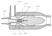
USP6,138,456公報に開示されているエジェクタは、上記の状態を実現する一つの方策を提供している。図10は同公報に示されたエジェクタの断面図である。図10において、110は一次流体供給配管、111は二次流体供給配管、112は一次流体供給配管110の先端部に取り付けられたノズル、113はディフューザ、114はノズル112に対向して回転自在に設けられた円錐体状のロータで、その円錐表面には複数の羽根115が取り付けられている。116はロータ114を支持する軸、117はディフューザ113内に同心に固定されたスピンドルで、ロータ114を同心軸上で支持する紡錘形状の部材である。
【0005】
このエジェクタは、ノズル112の噴射口に対向して極低摩擦で自由回転する円錐体状のロータ114を配設し、このロータ114の円錐面上に複数の傾斜した羽根115を設け、この羽根115付きロータ114をディフューザ113内に同軸に支持する構成となっている。かかるエジェクタの構成によると、ノズル112からの一次流体の噴流がロータ114に取り付けられた羽根115に作用し、ロータ114が自由回転する。回転しているロータ114の羽根115が横切る下流側には、一次流体のらせん流が形成される。このらせん流の速度成分は、エジェクタ軸方向に大きな速度成分を持つ。二次流体はこの一次流体らせん流のらせんとらせんの間に保持され、あたかもらせん形状のピストンで押されるようにして運搬される。この際、一次流体と二次流体の界面が、流体の速度方向に対して平行ではなく、らせんの強さに応じた角度を有するため、容積ポンプ的な現象に近くなり、せん断により巻き込む従来方式に比較してエントロピの増大、すなわち有効エネルギーの損失を低減することができる。さらに、一次流体と二次流体が、その界面を介してエネルギー(圧力)を交換して概略等エネルギー状態となった後に混合するため、エネルギー状態の異なる流体が直接混合する場合に比較して有効エネルギー損失を抑制することができる。これらの効果により、エジェクタの効率が向上する。この一次流体および二次流体のらせん流は「非定常流(non-steady flow)」と呼ばれている。ここに、非定常流とは、流量、速度、圧力、温度などの状態が時間的、空間的に変化する流れをいう。
【0006】
【発明が解決しようとする課題】
上記のようにUSP6,138,456公報によるエジェクタは、一次流体の非定常らせん流を生成し、これによりエジェクタの効率を向上させている。
しかしながら、このエジェクタでは、自由回転する羽根付きロータをノズル下流側に設置する必要があるため、エジェクタ構造が従来のものに比較して複雑となり、また、稼働部となる回転体の回転軸、軸受の耐久性などから、メンテナンスの必要が生じる。さらに、一次流体と二次流体の界面が流体の速度方向に対して鉛直にはなり得ないという問題点もある。一次流体と二次流が、その界面を介してエネルギー(圧力)を最も効率よく交換するためには、界面が流体の速度方向に対して鉛直であることが望ましい。界面が速度方向に対して鉛直でない場合には、界面と平行方向の速度成分に起因するせん断による巻き込みが発生し、効率が低下してしまうためである。USP6,138,456公報のらせん流は、羽根付きロータの羽根取付角度によりらせんの強さを調整可能である。羽根取付角度を一次流体噴流速度方向に対して鉛直に近づけることにより、一次流体/二次流体界面の速度方向に対する角度を鉛直に近づけることは可能であるが、真の鉛直にはなり得ない。また、羽根取付角度を一次流体噴流速度方向に対して鉛直に近づけることは、一次流体流れに対して抵抗となり、別の意味で効率を低下させてしまう。
【0007】
本発明は、かかる課題を解決するためになされたもので、比較的簡単な構成で一次流体を非定常流とし、さらに一次流体と二次流体の界面が流体流れ方向に対してほぼ鉛直となるようにすることにより、有効エネルギーの損失を抑制し、エジェクタの効率を向上することができるエジェクタおよびこれを用いた冷凍システムを提供することを目的としている。
【0008】
【課題を解決するための手段】
本発明に係るエジェクタは、一次流体を供給するノズルと、二次流体を供給する導入部を有するディフューザとを備え、一次流体の噴流によって二次流体の吸引および/または昇圧を行うエジェクタにおいて、
一次流体供給制御装置の周期的流量制御により一次流体の非定常流を生成し、一次流体塊と二次流体塊を交互に流動させてなることを特徴とするものである。
この構成によって、一次流体と二次流体の界面がエジェクタ軸方向に対してほぼ垂直となるように、一次流体の非定常流が生成される。なお、ここでいう界面とは、必ずしも明確な境界があるものだけではなく、遷移層のようなものも含める。
【0009】
本発明のエジェクタにおいては、非定常流の形態を間欠流または脈動流とするものである。
ここに、「間欠流」とは、間欠的に流体が一方向に流動する流れをいい、流体の流量が0となる瞬間があるものである。「脈動流」は、流体の流量が主流方向に時間変動する形態で、流量が最小となった瞬間でも0にはならないものを指す。
このような間欠流あるいは脈動流とすることによって、一次流体の非定常流を生成することが可能となる。二次流体は一次流体塊同士の狭間にはさまれ保持される状態となり、両流体間の界面は流体の流れ方向に対してほぼ鉛直となる。
【0010】
以上のような、一次流体の非定常流は、(1)一次流体供給配管内に設けた内管の周期的加熱制御、(2)一次流体供給装置の周期的供給制御、(3)一次流体供給制御装置の周期的流量制御、(4)一次流体加熱装置への高電場の周期的印加制御のいずれかの方法により生成することができる。
【0011】
(1)の方法では、一次流体供給配管内に設けた内管を周期的に加熱することによって、内管内の液を蒸発させ、その気泡によって液を吐出させる。これをノズルに導き、気相となった一次流体をノズル先端から噴出させることにより、一次流体の非定常流を生成することができる。
【0012】
(2)の方法では、一次流体供給装置として、例えばダイヤフラムポンプの如き間欠押し出し式のものを用い、これを周期的に制御するものである。
【0013】
(3)の方法では、一次流体供給制御装置として、例えば電磁弁等を用い、これを周期的に開閉制御するものである。
【0014】
(4)の方法では、一次流体加熱装置内に、例えば絶縁被覆電極を設け、これに高電場を周期的に印加することにより、加熱装置内の一次流体の蒸発量の増減を間欠的に行うものである。
【0016】
本発明の冷凍システムは、請求項1乃至9のいずれかに記載のエジェクタを用いて冷凍サイクルを構成したことを特徴とする。
【0017】
本発明のエジェクタは、一次流体を非定常流かつ二次流体との界面を流れ方向に鉛直としたことにより、二次流体の吸引・混合時の有効エネルギー損失が低減し、エジェクタの効率が向上する。言い換えれば、一次流体に対する二次流体の流量比(=[二次流体流量]/[一次流体流量])が増大し、単位量の二次流体を吸引するに必要な一次流体量が低減される。因みに、図9の従来例を用いた冷凍システムと比較すると、本発明では同一量の二次流体を吸引するに必要な一次流体量が1/3以下に低減され、すなわち、効率が3倍以上に向上する。
【0018】
【発明の実施の形態】
以下、本発明の実施の形態を図面を用いて説明する。
【0019】
実施の形態1.
図1は、本発明の実施の形態1によるエジェクタの概要を示す図である。
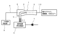
このエジェクタ1は、ノズル2と、内部にノズル2を同心状に配したディフューザ3とから主として構成されている。ディフューザ3は上流側に導入部4を有し、ノズル2はこの導入部4を貫く一次流体供給配管5の先端部に取り付けられている。ノズル2は、一次流体供給配管5により、一次流体加熱装置6を介してポンプなどからなる一次流体供給装置7に接続されており、また、ディフューザ3の導入部4には、二次流体供給配管8を介して二次流体の供給元である二次流体供給部9が接続されている。ディフューザ3は流出配管10を介して他のプロセス、凝縮器、あるいは大気などへ接続されている。
【0020】
図1には、一次流体の非定常流生成手段の一例として、内管を細管群11により構成したものが示されている。この細管群11は、一次流体供給配管5の内部上流側に設置され、一次流体加熱装置6に接続されている。また、細管群11は、図2に示すように、細管12を複数本束ねた構成となっており、それぞれの細管12の先端部に加熱手段13を設けたものである。加熱手段13は、例えば電気ヒータであり、細管12を周期的、かつ、瞬間的に加熱するものである。
【0021】
図3は、加熱手段13によって細管12を加熱したときの一次流体の吐出現象を模式的に示したものである。すなわち、一次流体加熱装置6を通過後、過熱液相状態となっている一次流体が細管12に充填されている状態で、加熱手段13により瞬間的に加熱した場合、液の一部が蒸発し、蒸発した気泡14が一気に膨張することにより、細管12内の加熱部13より先端側に存在する加熱液を細管12より押し出す。押し出された加熱液の液滴15は蒸発、膨張しつつノズル2に至り、ノズル2から高速度で噴出することになる。細管群11における細管12の本数は一次流体の流量に応じて任意の数としてよい。
【0022】
このように、加熱手段13で瞬間加熱を周期的に繰り返すことにより、間欠的な一次流体流れが生成される。図4はその間欠的な一次流体流れがエジェクタ1内部で生成されている状況を図示したものである。間欠的な一次流体流れにより、一次流体塊16が図4の右方向に流動し、それら一次流体塊16の狭間に二次流体が吸引され、二次流体塊17が形成され、やはり右方向へ流動する。一次流体塊16と二次流体塊17の間の界面は、流体塊の流れ方向に対し、概略垂直面をなし、一次流体塊16と二次流体塊17の間ではエネルギーの授受が行われる。エネルギーの授受後、ほぼ同一エネルギー状態となった一次流体塊16と二次流体塊17は混合し、ディフューザ3で速度エネルギーを圧力エネルギーに回復しつつ流出配管10へと流出する。したがって、一次流体塊16と二次流体塊17のエネルギー授受は垂直界面を介して行われ、また、両流体のエネルギー状態が近くなってから混合するため、有効エネルギーの損失が抑制され、エジェクタの効率が向上する。
なお、加熱手段13は、上記のように電気ヒータを用い、これにパルス電流を周期的に印加することにより上記機能を持たせることが可能となるが、電気ヒータ以外の加熱手段で断続的に各細管12を加熱しても構わない。
【0023】
実施の形態2.
図5は、本発明の実施の形態2によるエジェクタの概略図である。この実施の形態では、図1に示したような細管群11に代えて、一次流体の非定常流生成手段の他の例を示すものであり、一次流体供給装置7として、間欠流もしくは脈動流を発生させる構造のものを使用することにより、間欠的もしくは脈動的な一次流体流れを生成するものである。このような一次流体供給装置7の例として、ダイヤフラムポンプやチューブポンプなどがある。
【0024】
実施の形態3.
図6は、本発明の実施の形態3によるエジェクタの概略図である。この実施の形態では、実施の形態2と異なり、一次流体供給装置7と一次流体加熱装置6との間に、一次流体供給制御装置18を設置したもので、一次流体供給制御装置18によって一次流体の流れに間欠流もしくは脈動流を発生させるものである。このような一次流体供給制御装置18の例として、電磁弁などがある。なお、図6では一次流体供給制御装置18は、一次流体供給装置7と一次流体加熱装置6の間に設置してあるが、一次流体加熱装置6の下流側や、一次流体供給装置7の上流側など、任意の位置に設置可能である。
【0025】
実施の形態4.
図7は、本発明の実施の形態4によるエジェクタの概略図である。この実施の形態では、一次流体の非定常流生成手段のさらに他の例として、いわゆる「浅川効果」と称される方法を狙いとするものである。すなわち、一次流体加熱装置6は、内部に熱交換器19などを備えており、内部で一次流体を蒸発させる構造となっている。この加熱装置6の内部には、気相部に高圧電場を印加するための絶縁被覆電極20が設置してあり、高電圧電源21により電圧が印加されている。高圧電場を印加することにより、流体の表面張力の低下、粘性の低下が生じ、一次流体の蒸発が促進される(浅川効果)。したがって、高圧電場をパルス的、周期的に印加することにより、間欠的もしくは脈動的な一次流体流れが生成される。なお、図7では高電圧電源21は直流電源となっているが、交流電源であっても構わない。
【0026】
上述した一次流体の非定常流は、数Hz〜数十Hzの間欠流または脈動流となるように制御される。
【0027】
実施の形態5.
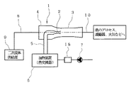
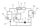
図8は、本発明のエジェクタを用いて冷凍サイクルを構成した実施の形態を示す概要図である。
エジェクタ1は、ノズル2、ディフューザ3により主として構成される。ノズル2は、一次流体供給配管5を介して、一次流体加熱装置6、一次流体供給装置7に接続されている。また、エジェクタ1は二次流体供給配管8を介して蒸発器51に接続されている。エジェクタ1の流出側には流出配管10を介して凝縮器52が接続されている。凝縮器52に流入する一次流体と二次流体の混合気は凝縮器52に接続されている冷却水配管54により冷却され、凝縮する。凝縮した液は、配管58を流れ、一次流体供給装置7により一次流体加熱装置6に戻されると同時に、二次流体戻り配管59、減圧弁57を介して蒸発器51に戻る。
蒸発器51内の二次流体がエジェクタ1により吸引される際に発生する二次流体の気化熱(蒸発潜熱)により温度低下、すなわち冷凍が発生し、蒸発器51に接続されている冷熱負荷56を冷却する。
【0028】
このエジェクタ1を用いることにより、上述したようにエジェクタの効率が向上するため、一次流体に対する二次流体の流量比(=[二次流体流量]/[一次流体流量])が増大し、冷凍機としての効率(COP)が向上する。
【0029】
なお、一次流体加熱装置6に接続されている熱交換器19の熱源としては、電力や燃料の燃焼によるもののほか、工場排熱や排ガス熱なども利用される。また、一次、二次流体の冷媒としては、水、フロン、アルコール、アンモニア、あるいはこれらの混合物などが利用される。
【0030】
【発明の効果】
以上のように、本発明のエジェクタは、簡単な構成であるうえに、ノズルから噴出する一次流体の流れを、一次流体と二次流体の界面がエジェクタ軸方向に対してほぼ垂直となるような非定常流とするものであるので、有効エネルギーの損失が抑制され、エジェクタの効率を大幅に向上させる効果がある。
また、本発明のエジェクタを用いた冷凍システムでは、単位量の二次流体を吸引するに必要な一次流体の流量が低減できることから、一次流体に対する二次流体の流量比が増大し、冷凍機の効率が向上する効果が得られる。
【図面の簡単な説明】
【図1】本発明の実施形態1によるエジェクタの概要図である。
【図2】図1の細管群を示す概略図である。
【図3】細管群における一次流体の吐出現象を示す説明図である。
【図4】本発明のエジェクタにおける一次流体と二次流体の流れを示す作用説明図である。
【図5】本発明の実施形態2によるエジェクタの概要図である。
【図6】本発明の実施形態3によるエジェクタの概要図である。
【図7】本発明の実施形態4によるエジェクタの概要図である。
【図8】本発明の実施形態5による冷凍システムの概要図である。
【図9】従来のエジェクタの概要図である。
【図10】USP6,138,456公報に示されたエジェクタの断面図である。
【符号の説明】
1 エジェクタ
2 ノズル
3 ディフューザ
4 導入部
5 一次流体供給配管
6 一次流体加熱装置
7 一次流体供給装置
8 二次流体供給配管
9 二次流体供給部
10 流出配管
11 細管群
12 細管
13 加熱手段
16 一次流体塊
17 二次流体塊
18 一次流体供給制御装置
20 絶縁被覆電極
21 高電圧電源
51 蒸発器
52 凝縮器[0001]
TECHNICAL FIELD OF THE INVENTION
The present invention relates to an ejector used for vacuum generation, compression, pressure increase, and the like, and more particularly, to an ejector in which the flow of a primary fluid is an unsteady flow, and a refrigeration system using the same.
[0002]
[Prior art]
As shown in FIG. 9, a conventional ejector includes a
In the conventional ejector, the primary fluid and the secondary fluid are mixed and sheared by the primary fluid at the
[0003]
In order to suppress the loss of effective energy and improve the efficiency of the ejector, when the high-energy fluid and the low-energy fluid are in direct contact, the interface between the two fluids must be perpendicular to their flow direction. desirable. In other words, it is desirable that the fluid flows in the normal direction of the interface between the two fluids. In this state, transfer of energy (pressure) is reversibly performed via the interface between the fluids in a state where the two fluids do not mix as much as possible. Further, the high-energy fluid and the low-energy fluid exchange energy via the interface, and are mixed after being in a substantially same energy state. For this reason, the effective energy loss at the time of suction / mixing is significantly reduced as compared with the case of shearing.
Such a state in which the interface between the high-energy fluid and the low-energy fluid is perpendicular to the direction of their flow cannot be realized when the primary fluid jet flows constantly as in a conventional ejector. It is.
[0004]
The ejector disclosed in US Pat. No. 6,138,456 provides one way to achieve the above condition. FIG. 10 is a cross-sectional view of the ejector disclosed in the publication. In FIG. 10, 110 is a primary fluid supply pipe, 111 is a secondary fluid supply pipe, 112 is a nozzle attached to the tip of the primary
[0005]
In this ejector, a
[0006]
[Problems to be solved by the invention]
As described above, the ejector according to US Pat. No. 6,138,456 produces an unsteady spiral flow of the primary fluid, thereby improving the efficiency of the ejector.
However, in this ejector, it is necessary to install a freely-rotating bladed rotor downstream of the nozzle, so that the ejector structure is more complicated than that of the conventional one, and the rotating shaft of the rotating body and the bearing, Maintenance is required due to the durability of the device. Further, there is a problem that the interface between the primary fluid and the secondary fluid cannot be vertical to the velocity direction of the fluid. In order for the primary fluid and the secondary flow to exchange energy (pressure) through the interface most efficiently, it is desirable that the interface be perpendicular to the velocity direction of the fluid. This is because if the interface is not perpendicular to the speed direction, entrainment due to shearing due to the speed component in the direction parallel to the interface occurs, and the efficiency is reduced. In the spiral flow disclosed in US Pat. No. 6,138,456, the strength of the spiral can be adjusted by adjusting the blade mounting angle of the bladed rotor. By making the blade mounting angle close to the vertical direction with respect to the primary fluid jet velocity direction, it is possible to make the angle of the primary fluid / secondary fluid interface with respect to the velocity direction close to vertical, but it cannot be true vertical. Further, making the blade mounting angle perpendicular to the primary fluid jet velocity direction becomes a resistance to the primary fluid flow, and lowers the efficiency in another sense.
[0007]
The present invention has been made to solve such a problem, and makes the primary fluid an unsteady flow with a relatively simple configuration, and furthermore, the interface between the primary fluid and the secondary fluid is substantially vertical to the fluid flow direction. By doing so, an object of the present invention is to provide an ejector capable of suppressing the loss of effective energy and improving the efficiency of the ejector, and a refrigeration system using the ejector.
[0008]
[Means for Solving the Problems]
An ejector according to the present invention includes a nozzle for supplying a primary fluid, and a diffuser having an introduction unit for supplying a secondary fluid, and an ejector that suctions and / or pressurizes a secondary fluid by a jet of the primary fluid.
An unsteady flow of the primary fluid is generated by periodic flow control of the primary fluid supply control device, and the primary fluid mass and the secondary fluid mass are caused to flow alternately .
With this configuration, the unsteady flow of the primary fluid is generated such that the interface between the primary fluid and the secondary fluid is substantially perpendicular to the ejector axis direction. It should be noted that the term “interface” as used herein does not necessarily mean a boundary having a clear boundary but also a transition layer.
[0009]
In the ejector of the present invention, the form of the unsteady flow is an intermittent flow or a pulsating flow.
Here, the “intermittent flow” refers to a flow in which the fluid intermittently flows in one direction, and there is a moment when the flow rate of the fluid becomes zero. “Pulsating flow” refers to a form in which the flow rate of a fluid fluctuates in the main flow direction with time, and does not become 0 even at the moment when the flow rate becomes minimum.
With such intermittent flow or pulsatile flow, it is possible to generate a non-steady flow of the primary fluid. The secondary fluid is sandwiched and held between the primary fluid masses, and the interface between the two fluids is substantially perpendicular to the flow direction of the fluid.
[0010]
The unsteady flow of the primary fluid as described above includes (1) periodic heating control of the inner pipe provided in the primary fluid supply pipe, (2) periodic supply control of the primary fluid supply device, and (3) primary fluid. It can be generated by any of the following methods: periodic flow control of the supply control device, and (4) periodic application control of a high electric field to the primary fluid heating device.
[0011]
In the method (1), the liquid in the inner pipe is evaporated by periodically heating the inner pipe provided in the primary fluid supply pipe, and the liquid is discharged by the bubbles. This is guided to the nozzle, and the primary fluid in the gas phase is ejected from the nozzle tip, whereby an unsteady flow of the primary fluid can be generated.
[0012]
In the method (2), an intermittent extrusion type device such as a diaphragm pump is used as a primary fluid supply device, and this is periodically controlled.
[0013]
In the method (3), for example, an electromagnetic valve or the like is used as the primary fluid supply control device, and this is periodically controlled to open and close.
[0014]
In the method (4), for example, an insulating coating electrode is provided in the primary fluid heating device, and a high electric field is periodically applied to the electrode to intermittently increase or decrease the evaporation amount of the primary fluid in the heating device. Things.
[0016]
A refrigeration system according to the present invention is characterized in that a refrigeration cycle is configured using the ejector according to any one of claims 1 to 9 .
[0017]
In the ejector of the present invention, the primary fluid is unsteady flow and the interface with the secondary fluid is vertical in the flow direction, so that the effective energy loss during suction and mixing of the secondary fluid is reduced, and the efficiency of the ejector is improved. I do. In other words, the flow rate ratio of the secondary fluid to the primary fluid (= [secondary fluid flow rate] / [primary fluid flow rate]) increases, and the amount of primary fluid required to suction a unit amount of secondary fluid is reduced. . By the way, in comparison with the refrigeration system using the conventional example of FIG. 9, in the present invention, the amount of the primary fluid required to suck the same amount of the secondary fluid is reduced to 1/3 or less, that is, the efficiency is 3 times or more. To improve.
[0018]
BEST MODE FOR CARRYING OUT THE INVENTION
Hereinafter, embodiments of the present invention will be described with reference to the drawings.
[0019]
Embodiment 1 FIG.
FIG. 1 is a diagram showing an outline of an ejector according to Embodiment 1 of the present invention.
The ejector 1 mainly includes a
[0020]
FIG. 1 shows an example of the means for generating an unsteady flow of a primary fluid in which an inner tube is constituted by a group of
[0021]
FIG. 3 schematically shows a primary fluid discharge phenomenon when the
[0022]
Thus, by intermittently repeating the instantaneous heating by the heating means 13, an intermittent primary fluid flow is generated. FIG. 4 illustrates a situation where the intermittent primary fluid flow is generated inside the ejector 1. Due to the intermittent primary fluid flow, the
The heating means 13 can use the electric heater as described above and apply the pulse current to the electric heater periodically to provide the above function. However, the heating means other than the electric heater is intermittently used. Each
[0023]
FIG. 5 is a schematic diagram of an ejector according to
[0024]
FIG. 6 is a schematic diagram of an ejector according to
[0025]
Embodiment 4 FIG.
FIG. 7 is a schematic diagram of an ejector according to Embodiment 4 of the present invention. This embodiment aims at a method referred to as the so-called "Asakawa effect" as still another example of the means for generating the unsteady flow of the primary fluid. That is, the primary
[0026]
The unsteady flow of the primary fluid described above is controlled so as to be an intermittent flow or a pulsating flow of several Hz to several tens Hz.
[0027]
FIG. 8 is a schematic diagram showing an embodiment in which a refrigeration cycle is configured using the ejector of the present invention.
The ejector 1 mainly includes a
A temperature drop, that is, freezing occurs due to heat of vaporization (latent heat of evaporation) of the secondary fluid generated when the secondary fluid in the
[0028]
By using the ejector 1, the efficiency of the ejector is improved as described above, so that the flow rate ratio of the secondary fluid to the primary fluid (= [secondary fluid flow rate] / [primary fluid flow rate]) increases, and the refrigerator Efficiency (COP) is improved.
[0029]
In addition, as a heat source of the
[0030]
【The invention's effect】
As described above, the ejector of the present invention has a simple structure, and furthermore, the flow of the primary fluid ejected from the nozzle is such that the interface between the primary fluid and the secondary fluid is substantially perpendicular to the ejector axial direction. Since the flow is unsteady, the loss of effective energy is suppressed, and the efficiency of the ejector is greatly improved.
Further, in the refrigeration system using the ejector of the present invention, since the flow rate of the primary fluid required to suck the unit amount of the secondary fluid can be reduced, the flow rate ratio of the secondary fluid to the primary fluid increases, and The effect of improving the efficiency is obtained.
[Brief description of the drawings]
FIG. 1 is a schematic diagram of an ejector according to a first embodiment of the present invention.
FIG. 2 is a schematic view showing a group of thin tubes in FIG. 1;
FIG. 3 is an explanatory view showing a discharge phenomenon of a primary fluid in a thin tube group.
FIG. 4 is an operation explanatory diagram showing flows of a primary fluid and a secondary fluid in the ejector of the present invention.
FIG. 5 is a schematic diagram of an ejector according to a second embodiment of the present invention.
FIG. 6 is a schematic diagram of an ejector according to a third embodiment of the present invention.
FIG. 7 is a schematic diagram of an ejector according to a fourth embodiment of the present invention.
FIG. 8 is a schematic diagram of a refrigeration system according to
FIG. 9 is a schematic view of a conventional ejector.
FIG. 10 is a sectional view of an ejector disclosed in US Pat. No. 6,138,456.
[Explanation of symbols]
DESCRIPTION OF SYMBOLS 1
Claims (9)
一次流体供給制御装置の周期的流量制御により一次流体の非定常流を生成し、一次流体塊と二次流体塊を交互に流動させてなることを特徴とするエジェクタ。 An ejector comprising a nozzle for supplying a primary fluid and a diffuser having an inlet for supplying a secondary fluid, wherein the ejector for suctioning and / or increasing the pressure of the secondary fluid by a jet of the primary fluid,
An ejector characterized in that an unsteady flow of a primary fluid is generated by periodic flow control of a primary fluid supply control device , and a primary fluid mass and a secondary fluid mass alternately flow .
一次流体供給配管内に設けた内管の周期的加熱制御により一次流体の非定常流を生成し、一次流体塊と二次流体塊を交互に流動させてなることを特徴とするエジェクタ。 An ejector comprising a nozzle for supplying a primary fluid and a diffuser having an inlet for supplying a secondary fluid, wherein the ejector for suctioning and / or increasing the pressure of the secondary fluid by a jet of the primary fluid,
An ejector characterized in that an unsteady flow of a primary fluid is generated by periodic heating control of an inner pipe provided in a primary fluid supply pipe, and a primary fluid mass and a secondary fluid mass flow alternately .
一次流体供給装置の周期的供給制御により一次流体の非定常流を生成し、一次流体塊と二次流体塊を交互に流動させてなることを特徴とするエジェクタ。 An ejector comprising a nozzle for supplying a primary fluid and a diffuser having an inlet for supplying a secondary fluid, wherein the ejector for suctioning and / or increasing the pressure of the secondary fluid by a jet of the primary fluid,
An ejector characterized in that an unsteady flow of a primary fluid is generated by periodic supply control of a primary fluid supply device , and a primary fluid mass and a secondary fluid mass alternately flow .
一次流体加熱装置への高電場の周期的印加制御により一次流体の非定常流を生成し、一次流体塊と二次流体塊を交互に流動させてなることを特徴とするエジェクタ。 An ejector comprising a nozzle for supplying a primary fluid and a diffuser having an inlet for supplying a secondary fluid, wherein the ejector for suctioning and / or increasing the pressure of the secondary fluid by a jet of the primary fluid,
An ejector characterized in that an unsteady flow of a primary fluid is generated by periodic application control of a high electric field to a primary fluid heating device, and a primary fluid mass and a secondary fluid mass alternately flow .
Priority Applications (1)
| Application Number | Priority Date | Filing Date | Title |
|---|---|---|---|
| JP2001141597A JP3589194B2 (en) | 2001-05-11 | 2001-05-11 | Ejector and refrigeration system |
Applications Claiming Priority (1)
| Application Number | Priority Date | Filing Date | Title |
|---|---|---|---|
| JP2001141597A JP3589194B2 (en) | 2001-05-11 | 2001-05-11 | Ejector and refrigeration system |
Related Child Applications (1)
| Application Number | Title | Priority Date | Filing Date |
|---|---|---|---|
| JP2003360104A Division JP2004076742A (en) | 2003-10-21 | 2003-10-21 | Method of improving efficiency of ejector and method of suppressing effective energy loss of ejector |
Publications (3)
| Publication Number | Publication Date |
|---|---|
| JP2002333000A JP2002333000A (en) | 2002-11-22 |
| JP2002333000A5 JP2002333000A5 (en) | 2004-10-28 |
| JP3589194B2 true JP3589194B2 (en) | 2004-11-17 |
Family
ID=18988028
Family Applications (1)
| Application Number | Title | Priority Date | Filing Date |
|---|---|---|---|
| JP2001141597A Expired - Fee Related JP3589194B2 (en) | 2001-05-11 | 2001-05-11 | Ejector and refrigeration system |
Country Status (1)
| Country | Link |
|---|---|
| JP (1) | JP3589194B2 (en) |
Cited By (1)
| Publication number | Priority date | Publication date | Assignee | Title |
|---|---|---|---|---|
| CN105452676A (en) * | 2013-08-01 | 2016-03-30 | 株式会社电装 | Ejector |
Families Citing this family (10)
| Publication number | Priority date | Publication date | Assignee | Title |
|---|---|---|---|---|
| FI122836B (en) * | 2008-12-05 | 2012-07-31 | Boildec Oy | Method and apparatus for emptying the bottom of a soda pan |
| JP5920110B2 (en) * | 2012-02-02 | 2016-05-18 | 株式会社デンソー | Ejector |
| JP6090104B2 (en) | 2012-12-13 | 2017-03-08 | 株式会社デンソー | Ejector |
| JP6119566B2 (en) | 2012-12-27 | 2017-04-26 | 株式会社デンソー | Ejector |
| JP6064862B2 (en) * | 2013-01-11 | 2017-01-25 | 株式会社デンソー | Ejector |
| JP6036592B2 (en) * | 2013-07-31 | 2016-11-30 | 株式会社デンソー | Ejector |
| JP6070465B2 (en) * | 2013-07-31 | 2017-02-01 | 株式会社デンソー | Ejector |
| JP6003844B2 (en) * | 2013-08-09 | 2016-10-05 | 株式会社デンソー | Ejector |
| CN108302014B (en) * | 2017-12-07 | 2024-02-23 | 中铁隧道局集团建设有限公司 | Air compressor economizer system |
| CN111520355B (en) * | 2020-05-18 | 2021-06-22 | 南京航空航天大学 | Adjustable phase and frequency unsteady flow control device based on bevel gear transmission |
-
2001
- 2001-05-11 JP JP2001141597A patent/JP3589194B2/en not_active Expired - Fee Related
Cited By (2)
| Publication number | Priority date | Publication date | Assignee | Title |
|---|---|---|---|---|
| CN105452676A (en) * | 2013-08-01 | 2016-03-30 | 株式会社电装 | Ejector |
| CN105452676B (en) * | 2013-08-01 | 2017-06-20 | 株式会社电装 | Injector |
Also Published As
| Publication number | Publication date |
|---|---|
| JP2002333000A (en) | 2002-11-22 |
Similar Documents
| Publication | Publication Date | Title |
|---|---|---|
| JP3589194B2 (en) | Ejector and refrigeration system | |
| CN102022387B (en) | Ejector | |
| KR101441765B1 (en) | A jet pump system for heat and cold management, apparatus, arrangement and methods of use | |
| CN101464069B (en) | Thermal injection and vortex flow combined air conditioner | |
| US7178360B2 (en) | Ejector | |
| WO2009070728A1 (en) | Thermally driven heat pump for heating and cooling | |
| CN101153757A (en) | Novel solar gas-injection refrigerating system | |
| JP2009299609A (en) | Ejector | |
| JP2004076742A (en) | Method of improving efficiency of ejector and method of suppressing effective energy loss of ejector | |
| JP2002333000A5 (en) | ||
| JP2002349500A (en) | Ejector and freezing system | |
| CN115523141A (en) | Vortex tube vapor recompression device | |
| JPH1137577A (en) | Nozzle device | |
| JP2003254300A (en) | Ejector and refrigeration system | |
| JP2005264747A (en) | Ejector, its operation method, and refrigerating system | |
| JP2005155571A (en) | Ejector and refrigerating system | |
| JPH0339867A (en) | Jet ejector type refrigeration method and apparatus | |
| CN101886855A (en) | Pressure-and-suction type refrigerating system | |
| JP2003247500A (en) | Ejector and refrigeration system | |
| CN109755193A (en) | power module life test cooling device | |
| JP2005016412A (en) | Ejector and freezing system | |
| CN217636209U (en) | Water tank of heat pump water heater | |
| CN219415328U (en) | Heating device for exhaust pipe of oil-gas separator | |
| JP2001124427A (en) | Cooling and heating device | |
| CN113074467B (en) | Ejector, and absorption type cooler and heater including the same |
Legal Events
| Date | Code | Title | Description |
|---|---|---|---|
| A131 | Notification of reasons for refusal |
Free format text: JAPANESE INTERMEDIATE CODE: A131 Effective date: 20031202 |
|
| A521 | Written amendment |
Free format text: JAPANESE INTERMEDIATE CODE: A523 Effective date: 20040129 |
|
| A131 | Notification of reasons for refusal |
Free format text: JAPANESE INTERMEDIATE CODE: A131 Effective date: 20040224 |
|
| A521 | Written amendment |
Free format text: JAPANESE INTERMEDIATE CODE: A523 Effective date: 20040420 |
|
| TRDD | Decision of grant or rejection written | ||
| A01 | Written decision to grant a patent or to grant a registration (utility model) |
Free format text: JAPANESE INTERMEDIATE CODE: A01 Effective date: 20040727 |
|
| A61 | First payment of annual fees (during grant procedure) |
Free format text: JAPANESE INTERMEDIATE CODE: A61 Effective date: 20040809 |
|
| R150 | Certificate of patent or registration of utility model |
Free format text: JAPANESE INTERMEDIATE CODE: R150 |
|
| FPAY | Renewal fee payment (event date is renewal date of database) |
Free format text: PAYMENT UNTIL: 20080827 Year of fee payment: 4 |
|
| S531 | Written request for registration of change of domicile |
Free format text: JAPANESE INTERMEDIATE CODE: R313531 |
|
| FPAY | Renewal fee payment (event date is renewal date of database) |
Free format text: PAYMENT UNTIL: 20080827 Year of fee payment: 4 |
|
| R350 | Written notification of registration of transfer |
Free format text: JAPANESE INTERMEDIATE CODE: R350 |
|
| FPAY | Renewal fee payment (event date is renewal date of database) |
Free format text: PAYMENT UNTIL: 20090827 Year of fee payment: 5 |
|
| FPAY | Renewal fee payment (event date is renewal date of database) |
Free format text: PAYMENT UNTIL: 20100827 Year of fee payment: 6 |
|
| LAPS | Cancellation because of no payment of annual fees |