JP3589052B2 - Winding device and winding inspection method - Google Patents
Winding device and winding inspection method Download PDFInfo
- Publication number
- JP3589052B2 JP3589052B2 JP32977198A JP32977198A JP3589052B2 JP 3589052 B2 JP3589052 B2 JP 3589052B2 JP 32977198 A JP32977198 A JP 32977198A JP 32977198 A JP32977198 A JP 32977198A JP 3589052 B2 JP3589052 B2 JP 3589052B2
- Authority
- JP
- Japan
- Prior art keywords
- winding
- wire
- shaft
- axial direction
- bobbin
- Prior art date
- Legal status (The legal status is an assumption and is not a legal conclusion. Google has not performed a legal analysis and makes no representation as to the accuracy of the status listed.)
- Expired - Lifetime
Links
Images


Description
【0001】
【発明の属する技術分野】
本発明は、コイル用の線材が巻付けられるボビン軸部において巻乱れの発生を巻線中に高精度で検査できる巻線装置および巻線検査方法に関する。
【0002】
【従来の技術】
一般に直状の軸部を有するボビンに線材を巻付けコイル、トランス類を製作する巻線方法は、ボビンまたは線材繰出用ノズルを往復動させ、回転するボビンの軸部に線材を該軸部の接線方向に輪状に巻きつける。その往復動の回数が層数となる。このような巻線方法を採るコイル、トランスでは各層ごとに線材が別れ、かつ一層内では等間隔に整列して巻かれることが好ましい。
【0003】
巻乱れを検査するため、例えば特開平8−124777号公報(以下、文献1という)では、ボビンまたは巻線繰出用ノズルの往復回数から線材の巻層数を求め、この巻層数に基づいて該巻層数の線材が正常にボビン上に巻付積層されたときの標準巻付外径を算出し、ボビンに巻付けられた線材の外周位置を検出する外径センサによりコイル実外径を計測し、このコイル実外径と前記標準巻付外径の差が所定値より大となったときに巻乱れが発生したと判定している。
【0004】
また、特開平9−55329号公報(以下、文献2という)では、レーザ発生源とその受光センサとからなるレーザセンサを用い、線材巻付け工程終了後に、レーザ発生源からのレーザ光がボビン軸部に直角に照射するようにレーザセンサを該軸部の軸方向に沿って走査し、その反射光が線材に当って反射する場合と、線材の下にある絶縁フィルムに当って反射する場合とで反射強度が変ることにより、巻乱れがあると判定している。
【0005】
【発明が解決しようとする課題】
従来の巻乱れ検査方法において、文献1では、線材巻付け工程の終了後に巻乱れの検査を行っており、巻乱れを検出したときには、その製品を破棄するしかなく、資源の無駄が多くなり生産性が極めて悪い。また、文献2では一層分の巻付けを終えるごとにその層について巻乱れの検査を行っている。従って、この従来技術では巻乱れを検出した場合には1層分全部を巻戻す等しなければならず、生産性がよいとはいえない。
【0006】
巻き乱れは、特に、巻線方法として、ボビン軸部の軸方向の一端側から徐々に巻端を他端側に進行させ、該一端側から他端側にかけて巻数が増減し巻端が階段状となる斜向巻きを行う場合は、巻端を形成する往復動のエンド位置が一往復ごとに変化するため、該エンド位置付近で巻乱れが発生しやすい。
また、文献1に記載された巻線検査方法では、層数が多い場合や線径が細い線材を巻く場合、必要検出精度を満足できない問題が発生する。
【0007】
また、文献2に記載された巻線検査方法では、検査工程の時間が必要であり、巻線作業全体からみた1つのコイル製作時間を長くする欠点がある。
本発明は、線材巻付け工程中に巻付け乱れを検出できる巻線装置および巻線検査方法並びにそれらを用いたコイル製造方法を提供することを解決すべき課題とする。
【0008】
【課題を解決するための手段】
本発明によれば、ボビンの軸部に線材を巻付けつつ、同時に線材の巻付け進行端近傍における線材の軸方向位置に関する情報を光学的に抽出し、この情報に基づいて線材の巻き乱れを検査する。
このようにすれば、線材巻付けが完了してから巻き乱れ検査を行うのではなく、巻き付け工程と同時にその巻き乱れ検査工程を実施するので、生産性に優れるとともに、巻き付け途中で巻き乱れを検出したらただちに巻き付けを終了することができるので、線材の無駄を低減することができる。
【0009】
更に、本発明では、線材の巻付け進行端近傍における線材の軸方向位置に関する情報を光学的に抽出するので、巻き乱れが生じれば、他の部位に比較して巻き乱れにより大きな反射率の変動を得ることができ、検出精度の向上を図ることができる。すなわち、巻付け進行端近傍での線材の有無を検出する場合には、僅かな巻き乱れでも確実に検出することができる。
【0010】
なお、上記光学的な情報抽出は、線材の巻付け進行端近傍にレーザー光などの光ビームのスポットを集中し、その反射ビームの強度で線材とそれ以外の地肌(軸部外周面やフィルム表面など)との反射率の差異を検出する他、線材の巻付け進行端近傍を含む領域をリニアセンサやエリアセンサなどの撮像手段で撮像することによっても上記反射率の差異を検出することができる。
【0011】
ここで、巻付け進行端とは、線材を普通に輪状に巻付ける場合の線材が巻き進む端をいい、斜向巻きの場合は、線材が巻き進む端または階段状に進む斜向部分の下側の端をいう。
たとえば、この巻付け進行端の所定部位、すなわち、巻付けられた線材の直前のターンの進行側に隣接する部位に線材が存在すれば、巻き乱れは存在せず、存在しなければ巻き乱れが生じたと判定することができる。もしくは、この巻付け進行端から軸方向進行側へ所定距離離れた部位に線材が巻付けられていれば巻き乱れが生じたと判定し、そうでなければ巻き乱れは存在しないと判定することができる。
【0012】
好適な態様において、照射ビームは、巻付け進行端から軸方向進行側に50〜1200μm離れた位置に照射する。換言すれば、巻付け進行端から軸方向進行側に50〜1200μm離れた位置における線材存在情報を光学的に検出する。線径が30〜600μm程度の通常の小型コイルでは、巻き乱れが生じると線材は、巻付け進行端から軸方向進行側に50〜1200μm離れた位置にずれるので、このようにすれば精度よく巻き乱れを判定することができる。なお、巻付け進行端から逸脱した線材を判定する場合、巻付け進行端から軸方向進行側に50μm未満の位置を光学的に調べる場合には巻き乱れかどうかを判定することが容易でなく、一方、それが1200μm以上離れた位置を光学的に調べる場合には巻き乱れが生じていたとしても線材を検出することが困難なために巻き乱れを検出することが容易でない。
【0013】
好適な態様において、時間順次に連続して所定回数、好適には4回以上、巻き乱れと判定する場合に、巻き乱れと最終判定する。このようにすれば、なんらかの原因により一時的に線材が巻付け進行端から軸方向進行側に所定距離ずれて、その後、また正常な巻付け進行端に復帰する場合に、それを巻き乱れと誤検出することがない。
【0014】
好適な態様において、ボビンの軸部に輪状に巻付けられる線材の予定された巻付け進行端あるいは該巻付け進行端より所定間隔離れた位置での前記線材の有無を照射ビームを発しその反射ビームを受信して該反射ビームの強度を示す信号を出力するセンサ手段を用いて検査することを特徴とする。
また、上記課題を同様に解決した本発明の巻線装置は、ボビンの軸部に輪状に巻付けられる線材の予定された巻付け進行端あるいは該巻付け進行端より所定間隔離れた位置での前記線材の有無を検査しつつ前記線材を前記軸部に巻付ける巻線装置であって、該軸部を一致して前記ボビンが装着される主軸と、該線材を繰出すノズル部をもつ線材供給手段と、該ノズル部から繰出される該線材が該ボビンの軸部に輪状に巻付けられるように該主軸を回転させつつ該軸部の軸方向に該ノズル部を該主軸に対して相対移動させる第1の駆動手段と、照射ビームを発しその反射ビームを受信して該反射ビームの強度を示す信号を出力するセンサ手段と、該センサ手段を保持する検査ヘッドをもち、該巻付け進行端に該センサ手段の照射ビームが同期するように該検査ヘッドを該主軸に対して該軸方向に相対移動させる第2の駆動手段とを具備したことを特徴とする。
【0015】
本発明の好適な態様では、線材が巻付けられる巻付け進行端あるいは該巻付け進行端より所定間隔離れた位置を狙ってセンサ手段の照射ビームが移動し、その巻付け進行端あるいは該巻付け進行端より所定間隔離れた位置での線材の有無を検出する。従って、線材巻付け工程中に線材が適正な位置に巻かれたか否かを検査することができる。なお、巻付け進行端より所定間隔離れた位置での線材の有無を検出するこの態様は、ある程度の巻き乱れが許される場合に特に有効である。
【0016】
照射ビームは、前記軸部に直角に交差する方向より巻付け進行側又はその反対側に傾斜した角度で該軸部に入射させることができる。この方法では、線材が巻付け進行端に有るときと無いときとで散乱による反射ビームの強弱差が明確となり、照射ビームを軸部に直角に照射する場合より正確に線材の有無を検査することができる。なお、巻付け進行側又はその反対側に傾斜させる角度は、5〜85°の範囲が好ましい。
【0017】
巻付け進行端あるいは巻付け進行端より所定間隔離れた位置での線材の有無は、軸部の表面あるいはその表面に被着される絶縁フィルムもしくは軸部に層状に巻付けられる線材の各層間に介装される絶縁フィルムと前記線材との反射率の相違に基づき反射ビームの前記信号がレベル変化することによって判定することができる。
【0018】
なお、本発明の方法では、線材の巻線方法として、巻端を軸部の軸方向の一端側から他端側へ徐々に進行させることにより一端側から他端側に向けて線材を上層側へ階段状に巻き付け、巻端が最上層のターンに到達後、巻端を軸部の軸方向の他端側から一端側へ徐々に進行させる斜向巻き方式を採用している。なお、上記巻端とは、本巻線方法によるその時点における最終巻き付け部を意味する。
【0019】
本発明の巻線装置は、前記センサ手段からの前記信号を入力しそのレベルの変化により前記巻付け進行端あるいは巻付け進行端より所定間隔離れた位置への前記線材の有無を判定する判定手段をもつことができる。これにより、線材巻付け工程中に巻乱れが発生したか否かを自動的に判定することができる。
【0020】
【発明の効果】
従って、本発明によれば、線材巻付け工程中に巻乱れの検査が同時に行われ、検査工程の時間を要しない。これによりコイル等の製作サイクルタイムを短くできると共に、資源の無駄を無くして生産性を高めることができる。
【0021】
【発明の実施の形態】
本発明の巻線検査方法は、ボビンの軸部に輪状に巻付けられる線材の予定された巻付け進行端の前記線材の有無を照射ビームを発しその反射ビームを受信して該反射ビームの強度を示す信号を出力するセンサ手段を用いて検査する。
ボビンは、その軸部の軸方向を回転する主軸の軸方向と一致して該主軸に装着することが好ましい。線材はノズル部をもつ線材供給手段より所定の張力で繰出す。該ノズル部は前記軸方向に沿って往復移動させる。これにより主軸によって回転する軸部に線材が巻付けられる。
【0022】
本発明において、通常の輪状にコイル等を巻く場合は、ノズル部と検査ヘッドとを一体化し、共通の駆動手段で移動させることができる。
斜向巻きを行う場合は、例えば軸部の一端側から他端側にかけて徐々に巻付け領域を増加させ、該一端側から他端側に巻数が傾斜状態に増減し巻端が階段状となるように巻付ける。この場合の検査ヘッドは、巻付け進行端が更新される斜向巻き部の下側巻端(巻端の更新端)と同期するように移動させ、ノズル部の移動に同期させる必要はない。
【0023】
センサ手段の照射ビームは、軸部の軸方向と直角より巻付け進行側又はその反対側に傾斜した角度で該軸部に入射させることが好ましい。
また、照射ビームは、レーザのようなコヒーレント光でも自然光でも使用できる。また、照射ビームは、軸部と直角に交差するように該軸部に照射してもよい
【0024】
。
【実施例】
以下に本発明の実施例を説明する。
(第1実施例)
第1実施例の巻線装置は、図1に示すように、サーボモータ1および該サーボモータ1によって回転駆動される装着用軸2を備えた主軸装置3と、該装着用軸2に装着されたボビン10に線材11を繰出すノズル部4aをもつ線材供給部材4と、該線材供給部材4を軸方向に移動自在となるようボールナットを介して支持したボールネジ5および該ホールネジ5を回転駆動するサーボモータ6からなるノズル駆動治具7と、該装着用軸2と平行に延びるボールネジ8、該ボールネジ8を回転駆動するサーボモータ9および該ボールネジ8にボールナットを介して軸方向に移動自在に支持された検査ヘッド12からなり、第2の駆動手段を構成する走査治具13と、照射窓および受光窓を有するプローブ部14が該検査ヘッド12に保持され、レーザ等の光源15および受光器16を具備したセンサ手段17とを主要素として構成され、第1の駆動手段は、該サーボモータ1、6によって構成されている。
【0025】
前記線材供給部材4は、図示しない線材供給機構から線材を引出しノズル部4aから所定の張力でボビン10へ繰出すように構成されている。なお、線材供給部材4は、ノズル部4aから突き出た線材10の先端をボビン10の巻付け初期位置へ係合させる手段をもつ。
センサ手段17のプローブ部14は、その照射窓から照射ビームをボビン10の軸部10aに対し巻付け進み側に傾斜した角度で入射させる。入射させる位置は、線材11が巻付けられる予定の巻付け進行端Tの位置である。また、照射ビームは図4に示すように、線材11の例えば軸心を狙って入射される。なお、プローブ部14は、それぞれ光源15および受光器16とそれぞれのファイバー18を介して接続されている。
【0026】
本実施例の検査装置では、受光器16の出力16aを判定する判定手段としての検査用コントローラ19を備えている。検査用コントローラ19は、巻付け進行端における線材11の有無を示す出力19aをサーボ系コントローラ20に入力している。サーボ系コントローラ20は、サーボモータ1、6および9を制御する信号1a、6aおよび9aを該サーボモータ1、6および9に出力している。これにより、巻線方法、巻付けピッチ等に応じた主軸2の回転速度、ノズル部4の移動速度および方向の切換え移動パターン等が所定の関係に制御される。検査ヘッド12の移動速度および方向の切換え移動パターンは、通常の輪状コイルを巻線する場合は、ノズル部4の移動速度および方向の切換え移動パターンと同じになる。斜向巻き部をもつコイルの場合は、斜向部分の巻端に同期させ、ノズル部4の移動速度および方向の切換え移動パターンと同じにする必要はない。
【0027】
ここで、斜向巻きは、図2に示すように、軸部10aの一端側から他端側へ徐々に巻端が進行し、外側の巻端が上層へ階段状になる巻き方である。この斜向巻きでは、巻付け進行端Tが符号T1に示すように既に巻かれた部分の上に重なる場合は問題でなく、そのまま上層に巻付けていってもかまわない。しかし、符号T2に示すように軸部10aの未巻付け部分に突出して巻付けが進行することは、後の巻付け状態を更に悪化するので巻乱れとする。
【0028】
次に上記巻線装置を用いた線材の巻付け工程を図2に示す斜向巻きを行う場合を例にして図3および図4を参照しつつ説明する。なお、図4において、照射ビームを示す2点鎖線は光軸を示すものである。図3に示すフローチャートは、検査用コントローラ19の動作の流れを示し、主軸2にボビン10がチャックされると開始され、初期設定としてのステップS1、S2が実行される。S1ではS1では巻線方法(ここでは斜向巻き)等を設定し、ステップS2ではノズル部4aの移動速度および移動パターン、主軸2の回転速度、照射ビーム走査位置および移動速度および移動パターン等を設定する。ノズル部4aの移動パターンは、斜向巻きの場合、往復ストロークが軸部10aの一端側から他端側へ徐々に大きくなるパターンとなる。検査ヘッド12の移動速度と移動パターンは、ノズル部4aの往復動に追従させる必要はなく、斜向巻き端が他端側へ広がる速度に合わせて低速で他端側への移動だけでよい。これによりプローブ部14から照射ビームが軸部10aに巻付けられる線材11の巻付け進行端Tを走査することになる。これらの初期設定は検査用コントローラ19からサーボ系コントローラ20に設定される。
【0029】
ステップS3により巻付けが開始されると、ステップS4〜S6が繰返される。即ち、S4〜S7は線材巻付け工程中に行われる巻乱れ検査工程であり、本実施例では斜向巻きを行うので、巻付け進行端Tが更新されるごとに行われる。巻付け進行端Tは、線材11が一端側から他端側に向う場合に、未巻付けの軸部10aに線材11が巻付けられたときに更新される。
【0030】
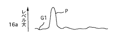
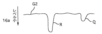
続くステップS5は検査用コントローラ19が受光器16からの出力16aを取込む処理である。ステップS6は取込んだ出力16aをレベル判定している。巻乱れの判定は、図4に示すように、巻付け進行端Tに線材11が存在するか否かで出力16aのレベルが図5、図6に示すように基準レベルG1、G2より上方向に突出するか基準レベルG1、G2かを調べる。出力16aのレベル変化は、実施例のように照射ビームを斜めに入射する場合、線材11が巻付け進行端Tに無いとき、線材11の表面と軸部10aの表面の反射率の相違によって図5または図6のようになる。線材11の表面の反射率が軸部10aの表面の反射率より小さいとき、図5のように巻乱れによりG1の上方向(レベル大)に変化する。線材11の表面の反射率が軸部10aの表面の反射率より大きいとき、図5のように巻乱れによりG2の下方向(レベル小)に変化する。軸部10aに表面が絶縁フィルムで覆われているとすると、線材11の絶縁物質の表面より反射率が大きく、その散乱分が反射ビームとなり、図5に示すように上方向に突出する。
【0031】
ステップS6の巻乱れ検出の詳細な動作を説明する。線材11が図4のAに示すように正常な巻付け進行端Tに位置していれば、反射ビームは大半が線材表面から反射した成分となり、出力16aにレベル変化は生じない。線材11が図4のBに示す位置に巻付けられた場合、反射ビームはLBに示すように照射ビームの反対側に逸れ、反射ビームとしてプローブ部14に戻る成分が小さくなる(図6の波形Q)。
【0032】
線材11が図4のCに示す位置に巻付けられた場合、照射ビームは軸部10aの表面だけに当って散乱する。このとき、主たる反射ビームは、Bの場合よりLC成分の散乱分が多くなり、出力16aは、Q波形より低いレベルのR波形に示す。検査用コントローラ19はこのレベル変化を巻乱れとして判定する。
ステップS6で巻乱れが無い(Y)と判定されると、検査用コントローラ19は巻終端か否かを判定し、巻終端でない場合(N)はステップS4に戻り、巻終端の場合(Y)は一つのコイルの巻付け工程を終了する(S8)。
【0033】
ステップS6で巻乱れ有り(N)と判定されると、検査用コントローラ19は、ステップS9に進み巻付け作業を停止する。この場合は、警報を発したり自動的に別の修正プログラムを実行等するか、人手により巻き乱れを修正することができる。
他の実施例として、照射ビームは軸部10aに直角に交差するように該軸部10aに入射させてもよい。この場合に得られる出力16aは、巻乱れを検出すると、図5に示す正方向に突出したレベル変化が現れる。
【0034】
照射ビームを軸部10aに直角に交差するように入射させる場合と、本実施例のように斜めに入射させる場合との相違は、本実施例では、反射率の大きい線材と小さい軸部であり、軸部の表面の反射率が前者の場合より大きくなっても検出可能である。
(第2実施例)
上記第1実施例においては、照射ビームを巻線の巻付け進行端Tに照射することによって、巻線の乱れを検出していたが、本第2実施例においては、巻線の進行方向の所定間隔はなれた箇所に、照射することを特徴とするものである。
【0035】
本第2実施例を図7を用いて説明する。
図7に示されるように、図示しない光源からの照射ビームBEは、赤色のLED光であり、巻付け進行端Tより、約1000μm離れた箇所を常にボビン10に対して垂直方向に照射するようになっている。
そのため、照射ビームBEを発する検査ヘッド12は、ノズル部(図示略)の横方向の移動に伴って、同横方向に移動できるようになっている。
【0036】
上記構成とすることによって、線材11が巻き乱れが生じない正常な時には、照射ビームBEがボビン10に照射されることになる。
ところが、巻き乱れが生じた場合には、照射ビームBEは、線材11に照射することになる。この時、巻線11に照射した場合の反射光の光量とボビン10に照射した場合の反射光の光量とが図7のA円内とB円内に模式的に示すように異なり、具体的には、巻線11に照射した場合の反射光の光量を約22mVとすると、ボビン10に照射した場合の反射光は、B円内に示すように散乱し、この時の光量は約20mVとなり、巻線11に照射した場合の光量の方が、大きいため、この光量の差を検出することによって、線材の巻き乱れを検出することができる。
【0037】
さらに、本第2実施例においては、光源からの照射ビームBEを、巻付け進行端Tより約1000μm離れた箇所を照射するようにした。
そのため、本第2実施例を採用すれば、巻き乱れがある程度(本第2実施例の場合では、約1000μm)以上の場合になって初めて巻き乱れであることを検出したい場合には、有効な手段である。
【0038】
(第3実施例)
本第3実施例においては、第2実施例に対して、更に照射ビームBEをボビン10の軸方向の直角方向に対する角度θとして、20゜斜めより照射することを特徴とする。この場合、検査ヘッド12は、光源部12Aと受光部12Bとに分れて配置される。
【0039】
その概略構成図を図8に示す。なお、図9にボビン10に対して垂直に照射した場合の照射部分を示し、図10にボビン10に対して斜めに照射した場合の照射部分を示す。
図9の場合では、ボビン10からの反射光も検出しているが、図10のように、斜めから照射ビームを照射した場合には、ボビン10からの反射光は、検出することがない。
【0040】
そのため、巻線11に照射した場合の反射光の光量(約22mV)の方が、ボビン10に照射した場合の反射光の光量(約16mV)よりも、垂直に照射ビームを照射した場合よりもはるかに大きいため、この光量の差を大きくすることができ、より精度よく線材の巻き乱れを検出することができる。
さらに、本第3実施例においては、照射ビームを斜めから照射しているため、線材の巻線方向に対して平行な線材の箇所では、照射ビームに対して、正反射により、反射光を検出することができる。それに対して、巻端と巻き乱れ部分の端部との間に存在する線材の箇所に照射ビームが照射された場合には、巻端と巻き乱れ部分の端部との間に存在する線材は、巻線方向に対して平行ではない。そのため、照射ビームによる反射光は検出することができない。
【0041】
以上のように、本第3実施例を採用することによって、巻き乱れがある程度(本第3実施例の場合では約1000μm)以上の場合になって初めて巻き乱れであることをより正確に検出することができる。
本第3実施例においては、照射ビームの照射角度θを20゜としたが、図11に示すように、5゜以上であれば、ボビン10からの反射光量を小とすることができ、線材からの反射光との差を大きくすることができる。
【0042】
しかしながら、85゜以下とした場合には、照射ビームで線材の巻き乱れを検出することができなくなるという問題が生じる。そのため、本第3実施例においては、照射ビームの照射角度は、ボビンの軸方向に対して直角方向より5〜85゜の範囲内で傾けるのが好ましい。
(第4実施例)
この第4実施例では、斜向巻きを行う際に巻線ノズルから斜向巻きによってノズルが移動する分(斜向巻き部分の幅(ボビン軸方向長さ))のオフセット長と規格幅分を離した位置にノズルと一体でセンサを取付ける(図12)。これにより斜向巻きの巻端の移動と同期してセンサを移動する軸が必要であったのが、ノズルの移動軸だけで巻き乱れの検出が可能となる。
(第5実施例)
上記第2実施例においては、巻線の巻付け進行端Tから進行方向へ所定間隔(50〜1200μm、更に好ましくは1000μm)離れた位置に照射ビームで照射して、線材11の有無を検査したが、この実施例では、図3に示すステップS5にて検査は一定インタバル(ここでは1mse)で順次実施される。そして、S6における判定においては、直前の連続する複数回(ここでは4回)の検査結果がすべて巻き乱れ(すなわち線材有り)と判定した場合に、最終的に巻き乱れと判定してステップS9に進み、そうでなければ巻き乱れなしと判定してステップS9に進む。
【0043】
このようにすれば、なんらかの原因により一時的に線材が巻付け進行端から軸方向進行側に所定距離ずれて、その後、また正常な巻付け進行端に復帰する場合に、それを巻き乱れと誤検出することがない。なお、このような線材11の軸方向進行側へのずれは、たとえば、線材が軸部上を滑ったり、押し出されたりして生じる場合がある。しかし、このようなずれは多くの場合には、線材11の張力により正規の位置すなわち巻付け進行端に復帰し、巻き乱れは解消される。したがって、この実施例により一時的な線材ずれを誤検出することがなく、検出精度の向上を実現することができる。
(変形態様)
なお、この第5実施例では、巻線の巻付け進行端Tから進行方向へ所定間隔(50〜1200μm、更に好ましくは100〜1000μm)離れた位置での時間的に連続する複数回の線材存在結果により初めて巻き乱れを判断したが、同じく実施例1で説明した巻付け進行端での時間的に連続する複数回の線材不存在結果により初めて巻き乱れと判定することもできる。
【0044】
更に、巻付け進行端での検査と巻付け進行端から進行側に所定距離離れた位置での検査を同時に行ってもよく、あるいはリニアセンサの画素セルを軸方向にならべて常時、線材位置をモニタすることもできる。
なお、線材の軸方向への一時的な位置ずれの発生からその解消までの時間は、通常、ボビンの回動角度で1440度すなわちこの実施例ではボビンが4回転する期間内に生じることから、反射光から一定インタバルで順次サンプリングされたデータをそれぞれ判定した各検査結果のうち、少なくとも一つの検査結果と、この検査結果を得たボビン角度位置に対して、このボビンの回動角度で1440度を超える角度位置にて検査した検査結果とを含む上記複数の検査結果がすべて巻き乱れを示す場合に最終的に巻き乱れと判定することが、上記一時的な線材ずれ(直後にずれ解消)を巻き乱れと誤判定しないために好ましい。
【図面の簡単な説明】
【図1】本発明の実施例に用いた巻線装置を示す概略構成図である。
【図2】斜向巻きと巻乱れを説明する説明図である。
【図3】実施例での動作を示すフロチャートである。
【図4】実施例の照射ビームを巻付け進行側に斜めの角度で軸部に交差させて入射させた場合の様子を示す動作説明図である。
【図5】実施例の受光器から得られる信号を示す波形図である。
【図6】上記信号の別の例を示す波形図である。
【図7】本発明の第2実施例を示す概略構成図である。
【図8】本発明の第3実施例を示す概略構成図である。
【図9】上記第3実施例の作用を説明するため、ボビンに対して垂直に照射した場合の照射部分を示す説明図である。
【図10】上記第3実施例の作用を説明するため、ボビンに対して斜めに照射した場合の照射部分を示す説明図である。
【図11】照射ビームを斜めにする場合の角度範囲を示すグラフであって、縦軸は反射強度、横軸は角度を表す。
【図12】本発明の第4実施例を示す説明図である。
【符号の説明】
1、6…サーボモータ、2…主軸、4a…ノズル部、5、8…ボールネジ、7…ノズル駆動手段(第1の駆動手段)、9…第2の駆動手段、10…ボビン、10a…軸部、12…検査ヘッド、13…走査治具、14…プローブ部、T…巻付け進行端。[0001]
TECHNICAL FIELD OF THE INVENTION
BACKGROUND OF THE
[0002]
[Prior art]
In general, a winding method of winding a wire around a bobbin having a straight shaft portion to produce a coil and a transformer is performed by reciprocating a bobbin or a wire feeding nozzle, and winding the wire around the shaft portion of a rotating bobbin. Wind tangentially in a ring. The number of reciprocating movements is the number of layers. In a coil and a transformer employing such a winding method, it is preferable that the wire material is separated for each layer, and that the wires are wound at equal intervals within one layer.
[0003]
In order to inspect the winding turbulence, for example, in Japanese Patent Application Laid-Open No. 8-124777 (hereinafter referred to as Document 1), the number of windings of the wire is obtained from the number of reciprocations of the bobbin or the nozzle for winding out, and the number of windings is determined based on the number of windings The standard winding outer diameter when the wire having the number of winding layers is normally wound and laminated on the bobbin is calculated, and the actual outer diameter of the coil is calculated by an outer diameter sensor that detects an outer peripheral position of the wire wound on the bobbin. When the difference between the actual coil outer diameter and the standard winding outer diameter becomes larger than a predetermined value, it is determined that the turbulence has occurred.
[0004]
In Japanese Patent Application Laid-Open No. 9-55329 (hereinafter referred to as Document 2), a laser sensor including a laser source and a light receiving sensor thereof is used, and after the wire winding process is completed, the laser beam from the laser source is supplied to a bobbin shaft. Scanning the laser sensor along the axial direction of the shaft portion so as to irradiate the portion at a right angle, and the case where the reflected light hits the wire and reflects, and the case where the light hits the insulating film under the wire and reflects. , It is determined that there is a turbulence.
[0005]
[Problems to be solved by the invention]
In the conventional winding disturbance inspection method, in
[0006]
In particular, as a winding method, the winding end gradually advances from one end in the axial direction of the bobbin shaft portion to the other end, and the number of windings increases and decreases from the one end to the other end, and the winding end is stepped. When the oblique winding is performed, the end position of the reciprocating motion forming the winding end changes every one reciprocation, so that winding disturbance is likely to occur near the end position.
Further, in the winding inspection method described in
[0007]
In addition, the winding inspection method described in
The present invention relates to a winding device and a winding inspection method capable of detecting winding disturbance during a wire winding process. And coil manufacturing method using the same Is to be solved.
[0008]
[Means for Solving the Problems]
According to the present invention While the wire is wound around the bobbin shaft, information about the axial position of the wire near the winding end of the wire is optically extracted at the same time, and the winding disturbance of the wire is inspected based on this information.
In this way, instead of conducting a winding disturbance inspection after the wire winding is completed, the winding disturbance inspection process is performed at the same time as the winding process, thereby improving productivity and detecting winding disturbance during winding. Then, the winding can be completed immediately, so that the waste of the wire can be reduced.
[0009]
Further, according to the present invention, since information on the axial position of the wire near the winding end of the wire is optically extracted, if the turbulence occurs, the turbulence has a higher reflectivity than the other parts. Variations can be obtained, and detection accuracy can be improved. That is, when detecting the presence or absence of a wire near the winding end, even a slight winding disturbance can be reliably detected.
[0010]
In the optical information extraction, the spot of a light beam such as a laser beam is concentrated near the winding end of the wire rod, and the intensity of the reflected beam is used to extract the wire rod and the other background (shaft outer peripheral surface or film surface). In addition to detecting the difference in reflectance, the difference in reflectance can also be detected by imaging an area including the vicinity of the winding end of the wire with an imaging unit such as a linear sensor or an area sensor. .
[0011]
Here, the winding progress end means the end where the wire is wound when the wire is normally wound in a ring shape, and in the case of oblique winding, the end where the wire is wound or below the inclined portion where the wire progresses stepwise. Side edge.
For example, if the wire is present at a predetermined portion of the winding advancing end, that is, at a portion adjacent to the advancing side of the turn immediately before the wound wire, the winding is not disturbed. It can be determined that it has occurred. Alternatively, if the wire is wound at a position separated by a predetermined distance from the winding advancing end to the axially advancing side, it is determined that a winding disturbance has occurred, and otherwise, it can be determined that there is no winding disturbance. .
[0012]
In a preferred embodiment, the irradiation beam is applied to a position 50 to 1200 μm away from the winding end in the axial direction. In other words, the wire rod presence information at a position 50 to 1200 μm away from the winding progress end toward the axial advance side is optically detected. In a normal small coil having a wire diameter of about 30 to 600 μm, if winding disturbance occurs, the wire is displaced from the winding end to a position 50 to 1200 μm away from the winding advance end in the axial direction, so that accurate winding can be achieved. Disorder can be determined. In addition, when judging the wire rod deviating from the winding advance end, when optically examining a position of less than 50 μm on the axial advance side from the winding advance end, it is not easy to determine whether the winding is disordered, On the other hand, when optically examining a position at a distance of 1200 μm or more, it is difficult to detect a wire even if a turbulence has occurred, so that it is not easy to detect the turbulence.
[0013]
In a preferred embodiment, when it is determined that the turbulence has occurred a predetermined number of times, preferably four times or more consecutively in time sequence, it is finally determined that the turbulence has occurred. In this way, if the wire rod temporarily shifts by a predetermined distance from the winding advance end to the axial advance side for some reason, and then returns to the normal winding advance end, it is mistaken as a winding disorder. There is no detection.
[0014]
In a preferred embodiment, an irradiation beam is emitted to determine the presence or absence of the wire at a predetermined winding proceeding end of the wire wound around the bobbin shaft portion at a predetermined interval or at a position spaced apart from the winding proceeding end by a predetermined distance. The inspection is performed using sensor means for receiving a signal and outputting a signal indicating the intensity of the reflected beam.
In addition, the winding device of the present invention, which also solves the above-described problem, is provided at a predetermined winding progress end of a wire rod wound around the bobbin shaft portion at a predetermined distance or at a position separated by a predetermined distance from the winding progress end. What is claimed is: 1. A winding device for winding said wire around said shaft while checking for the presence or absence of said wire, said wire comprising a main shaft on which said bobbin is mounted so that said shaft is aligned, and a nozzle portion for feeding said wire Supply means, and rotating the main shaft so that the wire rod fed from the nozzle portion is wound around the shaft portion of the bobbin in a ring shape, while moving the nozzle portion relative to the main shaft in the axial direction of the shaft portion. A first driving means for moving the sensor, a sensor means for emitting an irradiation beam, receiving the reflected beam and outputting a signal indicating the intensity of the reflected beam, and an inspection head for holding the sensor means; The irradiation beam of the sensor means is synchronized with the end. The inspection head, characterized by comprising a second driving means for relatively moving the axial direction relative to the spindle so.
[0015]
Departure Clear In a preferred aspect, the irradiation beam of the sensor means moves at a winding advancing end where the wire is wound or at a position separated by a predetermined distance from the winding advancing end, and is moved from the winding advancing end or the winding advancing end. The presence or absence of a wire at a position separated by a predetermined distance is detected. Therefore, it is possible to inspect whether or not the wire is wound at an appropriate position during the wire winding process. This mode of detecting the presence or absence of a wire at a position separated by a predetermined distance from the winding end is particularly effective when a certain degree of turbulence is allowed.
[0016]
The irradiation beam can be made incident on the shaft at an angle that is inclined to the winding progress side or the opposite side from the direction perpendicular to the shaft. In this method, the difference in the intensity of the reflected beam due to scattering between when the wire is at the winding end and when it is not is clear, and the presence or absence of the wire should be inspected more accurately than when irradiating the irradiation beam at right angles to the shaft Can be. The angle of inclination to the winding progress side or the opposite side is preferably in the range of 5 to 85 °.
[0017]
The presence or absence of a wire at a predetermined distance from the winding progress end or the winding progress end is determined between the surfaces of the shaft or an insulating film applied to the surface or between each layer of the wire wound in a layer on the shaft. The determination can be made by changing the level of the signal of the reflected beam based on the difference in reflectance between the interposed insulating film and the wire.
[0018]
The method of the present invention Then, as a winding method of the wire, as the winding end is gradually advanced from one end side in the axial direction of the shaft portion to the other end side, the wire is wound stepwise from one end side to the other end side toward the upper layer side, After the winding end reaches the turn of the uppermost layer, the oblique winding method is adopted, in which the winding end is gradually advanced from the other end in the axial direction of the shaft to one end. are doing . In addition, the said winding end means the last winding part at that time by this winding method.
[0019]
The winding device according to the present invention is characterized in that the signal from the sensor means is input, and the presence or absence of the wire at a predetermined distance from the winding end or the winding end is determined based on a change in the level. Can be included. Thereby, it is possible to automatically determine whether or not winding disturbance has occurred during the wire winding process.
[0020]
【The invention's effect】
Therefore, according to the present invention, the inspection for the turbulence is simultaneously performed during the wire winding process, and the time for the inspection process is not required. As a result, the cycle time for manufacturing coils and the like can be shortened, and the productivity can be increased by eliminating waste of resources.
[0021]
BEST MODE FOR CARRYING OUT THE INVENTION
According to the winding inspection method of the present invention, an irradiation beam is emitted to determine the presence or absence of the wire at a predetermined winding advancing end of the wire wound around the bobbin shaft portion in a loop shape, the reflected beam is received, and the intensity of the reflected beam is received. The inspection is performed using a sensor unit that outputs a signal indicating
The bobbin is preferably mounted on the main shaft so as to coincide with the axial direction of the main shaft rotating in the axial direction of the shaft portion. The wire is fed out at a predetermined tension from a wire supply means having a nozzle portion. The nozzle portion reciprocates along the axial direction. As a result, the wire is wound around the shaft that is rotated by the main shaft.
[0022]
In the present invention, when a coil or the like is wound in a normal ring shape, the nozzle portion and the inspection head can be integrated, and can be moved by common driving means.
When performing oblique winding, for example, the winding area is gradually increased from one end side to the other end side of the shaft portion, and the number of turns is increased and decreased from the one end side to the other end side, and the winding end becomes step-like. And wrap it. In this case, the inspection head is moved so that the winding progress end is synchronized with the lower winding end (renewal end of the winding end) of the oblique winding to be updated, and need not be synchronized with the movement of the nozzle unit.
[0023]
It is preferable that the irradiation beam of the sensor means is incident on the shaft at an angle inclined to the winding progress side or the opposite side from the direction perpendicular to the axial direction of the shaft.
As the irradiation beam, either coherent light such as laser light or natural light can be used. The irradiation beam may irradiate the shaft so as to intersect the shaft at a right angle.
[0024]
.
【Example】
Hereinafter, embodiments of the present invention will be described.
(First embodiment)
As shown in FIG. 1, the winding device of the first embodiment is provided with a
[0025]
The
The
[0026]
The inspection apparatus according to the present embodiment includes an
[0027]
Here, the oblique winding is, as shown in FIG. 2, a winding method in which the winding end gradually advances from one end side to the other end side of the
[0028]
Next, a wire winding process using the above-described winding device will be described with reference to FIGS. 3 and 4 by taking the case of performing oblique winding shown in FIG. 2 as an example. In FIG. 4, the two-dot chain line indicating the irradiation beam indicates the optical axis. The flowchart shown in FIG. 3 shows a flow of the operation of the
[0029]
When the winding is started in step S3, steps S4 to S6 are repeated. That is, S4 to S7 are winding disorder inspection steps performed during the wire winding step. In the present embodiment, since oblique winding is performed, the inspection is performed every time the winding progress end T is updated. The winding progress end T is updated when the
[0030]
The following step S5 is a process in which the
[0031]
The detailed operation of the winding turbulence detection in step S6 will be described. If the
[0032]
When the
If it is determined in step S6 that there is no winding disturbance (Y), the
[0033]
If it is determined in step S6 that there is winding turbulence (N), the
As another example, the irradiation beam may be incident on the
[0034]
The difference between the case where the irradiation beam is incident on the
(Second embodiment)
In the first embodiment, the turbulence of the winding is detected by irradiating the irradiation beam to the winding advance end T of the winding. In the second embodiment, however, the turbulence of the winding in the traveling direction is determined. It is characterized by irradiating a portion separated by a predetermined interval.
[0035]
The second embodiment will be described with reference to FIG.
As shown in FIG. 7, the irradiation beam BE from a light source (not shown) is a red LED light, and always irradiates the
For this reason, the
[0036]
With the above configuration, the irradiation beam BE is applied to the
However, when winding disturbance occurs, the irradiation beam BE irradiates the
[0037]
Further, in the present second embodiment, the irradiation beam BE from the light source is applied to a portion about 1000 μm away from the winding advance end T.
Therefore, if the second embodiment is adopted, it is effective when it is desired to detect the winding disturbance only when the winding disturbance is a certain degree (about 1000 μm in the case of the second embodiment). Means.
[0038]
(Third embodiment)
The third embodiment is characterized in that, compared to the second embodiment, the irradiation beam BE is irradiated obliquely at an angle θ of 20 ° with respect to the direction perpendicular to the axial direction of the
[0039]
FIG. 8 shows a schematic configuration diagram thereof. FIG. 9 shows an irradiated portion when the
In the case of FIG. 9, the reflected light from the
[0040]
Therefore, the amount of reflected light (approximately 22 mV) when irradiating the winding 11 is greater than the amount of reflected light (approximately 16 mV) when irradiating the
Further, in the third embodiment, since the irradiation beam is irradiated obliquely, the reflected light is detected by the regular reflection of the irradiation beam at the position of the wire parallel to the winding direction of the wire. can do. On the other hand, when the irradiation beam is irradiated to the wire portion existing between the winding end and the end of the winding disorder portion, the wire existing between the winding end and the end of the winding disorder portion is , Not parallel to the winding direction. Therefore, light reflected by the irradiation beam cannot be detected.
[0041]
As described above, by employing the third embodiment, it is possible to more accurately detect the occurrence of the turbulence only when the turbulence exceeds a certain level (about 1000 μm in the case of the third embodiment). be able to.
In the third embodiment, the irradiation angle θ of the irradiation beam is set to 20 °. However, as shown in FIG. 11, if the irradiation angle θ is 5 ° or more, the amount of light reflected from the
[0042]
However, if the angle is set to 85 ° or less, a problem arises in that it is not possible to detect winding disturbance of the wire with the irradiation beam. Therefore, in the third embodiment, it is preferable that the irradiation angle of the irradiation beam is inclined within a range of 5 to 85 ° from a direction perpendicular to the axial direction of the bobbin.
(Fourth embodiment)
In the fourth embodiment, when the oblique winding is performed, the offset length and the standard width corresponding to the movement of the nozzle from the winding nozzle by the oblique winding (width of the oblique winding portion (length in the bobbin axial direction)) are determined. The sensor is mounted integrally with the nozzle at the separated position (FIG. 12). Thus, an axis for moving the sensor in synchronization with the movement of the winding end of the oblique winding is required, but it is possible to detect a winding turbulence only with the movement axis of the nozzle.
(Fifth embodiment)
In the second embodiment described above, the position of a predetermined distance (50 to 1200 μm, more preferably 1000 μm) away from the winding advance end T of the winding in the traveling direction is irradiated with an irradiation beam, and the presence or absence of the
[0043]
In this way, if the wire rod temporarily shifts by a predetermined distance from the winding advance end to the axial advance side for some reason, and then returns to the normal winding advance end, it is mistaken as a winding disorder. There is no detection. Note that such a shift of the
(Modification)
In the fifth embodiment, a plurality of temporally continuous wire rods at predetermined distances (50 to 1200 μm, more preferably 100 to 1000 μm) apart from the winding advance end T of the winding in the traveling direction are used. Although the winding disturbance is determined for the first time based on the result, it is also possible to determine the winding disturbance only on the basis of the result of a plurality of temporally consecutive absences of the wire rod at the winding advancing end described in the first embodiment.
[0044]
Further, the inspection at the winding progression end and the inspection at a position away from the winding progression end by a predetermined distance from the winding progression end may be performed at the same time, or the position of the wire rod may be constantly determined by arranging the pixel cells of the linear sensor in the axial direction. You can also monitor.
Note that the time from the occurrence of the temporary displacement of the wire in the axial direction to the elimination thereof is usually 1440 degrees in the rotation angle of the bobbin, that is, in this embodiment, since the bobbin rotates four times, At least one inspection result among the inspection results obtained by sequentially judging data sequentially sampled at a constant interval from the reflected light and the bobbin angle position at which the inspection result was obtained is 1440 degrees in the rotation angle of the bobbin. If the plurality of inspection results including the inspection result inspected at an angle position exceeding the above all indicate winding disturbance, it is finally determined that the winding is disordered. This is preferable in order to prevent erroneous determination of winding disturbance.
[Brief description of the drawings]
FIG. 1 is a schematic configuration diagram showing a winding device used in an embodiment of the present invention.
FIG. 2 is an explanatory diagram illustrating oblique winding and winding disturbance.
FIG. 3 is a flowchart showing an operation in the embodiment.
FIG. 4 is an operation explanatory diagram showing a state in which the irradiation beam according to the embodiment is incident on the winding progress side at an oblique angle so as to intersect the shaft.
FIG. 5 is a waveform chart showing a signal obtained from the light receiver of the embodiment.
FIG. 6 is a waveform chart showing another example of the signal.
FIG. 7 is a schematic configuration diagram showing a second embodiment of the present invention.
FIG. 8 is a schematic configuration diagram showing a third embodiment of the present invention.
FIG. 9 is an explanatory view showing an irradiated portion when vertically irradiating a bobbin to explain the operation of the third embodiment.
FIG. 10 is an explanatory view showing an irradiated portion when obliquely irradiating a bobbin to explain the operation of the third embodiment.
FIG. 11 is a graph showing an angle range when the irradiation beam is inclined, wherein the vertical axis represents the reflection intensity and the horizontal axis represents the angle.
FIG. 12 is an explanatory view showing a fourth embodiment of the present invention.
[Explanation of symbols]
1, 6 servo motor, 2 spindle, 4a nozzle section, 5 8 ball screw, 7 nozzle driving means (first driving means), 9 second driving means, 10 bobbin, 10a axis Reference numeral 12: inspection head, 13: scanning jig, 14: probe part, T: winding end.
Claims (25)
前記情報は、前記線材の巻付け進行端近傍に照射ビームを発して受信した反射ビームの強度に関する情報からなり、
前記照射ビームを、前記巻付け進行端から軸方向進行側に所定間隔離れた位置に照射する巻線検査方法。 A winding inspection for optically extracting information on the axial position of the wire near the winding end of the wire while winding the wire around the shaft of the bobbin, and inspecting the winding disturbance of the wire based on the information. The method,
The information comprises information on the intensity of the reflected beam received by emitting an irradiation beam near the winding end of the wire rod,
The illumination beam, the winding examination how to irradiation at a distance predetermined distance axially advancing side from the winding progress end.
巻端を前記軸部の軸方向の一端側から他端側へ徐々に進行させることにより前記一端側から前記他端側に向けて前記線材を上層側へ階段状に巻き付け、前記巻端が最上層のターンに到達後、前記巻端を前記軸部の軸方向の他端側から一端側へ徐々に進行させる斜向巻き方式で前記軸部に巻き付けられた前記線材の前記巻付け進行端から軸方向に進行側に所定間隔離れた位置における前記線材の有無を光学的に検出することを特徴とする巻線検査方法。 A winding inspection for optically extracting information on the axial position of the wire near the winding end of the wire while winding the wire around the shaft of the bobbin, and inspecting the winding disturbance of the wire based on the information. The method,
By gradually advancing the winding end from one end side in the axial direction of the shaft portion to the other end side, the wire is wound stepwise from the one end side to the other end side toward the upper layer side, and the winding end is the most. After reaching the upper turn, the winding end of the wire rod wound around the shaft portion in an oblique winding method in which the winding end is gradually advanced from the other end side in the axial direction of the shaft portion to one end side. winding inspecting how to and detecting the presence or absence of the wire at a position spaced a predetermined distance in the traveling side in the axial direction optically.
ボビンの軸部に線材を巻付けつつ前記線材の巻付け進行端近傍における前記線材の軸方向位置に関する情報を光学的に抽出し、Optically extracting information on the axial position of the wire near the winding end of the wire while winding the wire around the bobbin shaft,
前記情報に基づいて前記線材の巻き乱れを判定し、Determine the turbulence of the wire based on the information,
巻乱れが無いと判定されると巻終端で巻付け工程を終了し、When it is determined that there is no winding disturbance, the winding process ends at the end of the winding,
巻乱れ有りと判定されると巻付けを停止することを特徴とするコイル製造方法。A method for manufacturing a coil, comprising: stopping winding when it is determined that winding disturbance is present.
前記照射ビームを、前記巻付け進行端から軸方向進行側に所定間隔離れた位置に照射することを特徴とする請求項19から22のいずれか1項に記載のコイル製造方法。The coil manufacturing method according to any one of claims 19 to 22, wherein the irradiation beam is applied to a position separated by a predetermined distance from the winding advance end to an axial advance side.
Priority Applications (1)
| Application Number | Priority Date | Filing Date | Title |
|---|---|---|---|
| JP32977198A JP3589052B2 (en) | 1997-11-19 | 1998-11-19 | Winding device and winding inspection method |
Applications Claiming Priority (3)
| Application Number | Priority Date | Filing Date | Title |
|---|---|---|---|
| JP31872097 | 1997-11-19 | ||
| JP9-318720 | 1997-11-19 | ||
| JP32977198A JP3589052B2 (en) | 1997-11-19 | 1998-11-19 | Winding device and winding inspection method |
Publications (2)
| Publication Number | Publication Date |
|---|---|
| JPH11233360A JPH11233360A (en) | 1999-08-27 |
| JP3589052B2 true JP3589052B2 (en) | 2004-11-17 |
Family
ID=26569480
Family Applications (1)
| Application Number | Title | Priority Date | Filing Date |
|---|---|---|---|
| JP32977198A Expired - Lifetime JP3589052B2 (en) | 1997-11-19 | 1998-11-19 | Winding device and winding inspection method |
Country Status (1)
| Country | Link |
|---|---|
| JP (1) | JP3589052B2 (en) |
Families Citing this family (4)
| Publication number | Priority date | Publication date | Assignee | Title |
|---|---|---|---|---|
| JP4821655B2 (en) * | 2007-02-28 | 2011-11-24 | マックス株式会社 | Wire rod cartridge and paper processing apparatus |
| CN102522195A (en) * | 2011-12-19 | 2012-06-27 | 吴江市合成电子机械厂 | Coiling machine for identical-weight coils |
| CN102522197A (en) * | 2011-12-21 | 2012-06-27 | 吴江市合成电子机械厂 | Automatic-rectification winding machine for mica plates |
| WO2022067756A1 (en) * | 2020-09-30 | 2022-04-07 | 深圳烯湾科技有限公司 | Control method for fiber winding and curing, and light-curing fiber winding device |
-
1998
- 1998-11-19 JP JP32977198A patent/JP3589052B2/en not_active Expired - Lifetime
Also Published As
| Publication number | Publication date |
|---|---|
| JPH11233360A (en) | 1999-08-27 |
Similar Documents
| Publication | Publication Date | Title |
|---|---|---|
| US10371507B2 (en) | Shape measurement device, structural object production system, shape measurement method, structural object production method, shape measurement program, and recording medium | |
| CN102792155B (en) | Surface inspection apparatus | |
| CN101952712A (en) | Device and method for optically detecting surface defect of round wire rod | |
| US10072925B2 (en) | Method and device for detection of rotated segments in a multi-segment rod transferred in a machine used in cigarette production industry | |
| JP2002508731A (en) | Method and apparatus for winding strand-like wound material on a spool | |
| JP3589052B2 (en) | Winding device and winding inspection method | |
| US6903814B1 (en) | Container sealing surface inspection | |
| CN1069602C (en) | Process and device for detecting the winding of thread on a rotating roller | |
| US20120075625A1 (en) | Optical surface defect inspection apparatus and optical surface defect inspection method | |
| JP2006301178A (en) | Bend sensor and its manufacturing method | |
| JP2008008689A (en) | Surface inspection device and surface inspection method | |
| EP3718939B1 (en) | Device and method for detecting the presence of abnormalities in a reel | |
| US5110065A (en) | Bobbin winding control | |
| JP5904195B2 (en) | Inspection device and inspection method for optical fiber ribbon | |
| JPH05310369A (en) | Winding state monitoring method | |
| US10031088B2 (en) | Measurement apparatus | |
| JP2014167429A (en) | Cylindrical body inspection apparatus | |
| WO2024090021A1 (en) | Pipe-like body cutting device and pipe-like body cutting method | |
| JP2001302093A (en) | Control method for regularly winding linear material around bobbin | |
| JP4723838B2 (en) | Surface defect inspection equipment | |
| JPS6358104A (en) | Measurement of fine interval | |
| WO2018101037A1 (en) | Method for positioning corrugated tube, method for manufacturing cut corrugated tube, device for positioning corrugated tube, and device for cutting corrugated tube | |
| JPH0382906A (en) | Detection of disturbance in aligned winding | |
| JP4407309B2 (en) | Strip width measuring method and apparatus, and carbon fiber manufacturing apparatus using the same | |
| JP4282108B2 (en) | Fuzz inspection device for yarn package |
Legal Events
| Date | Code | Title | Description |
|---|---|---|---|
| A977 | Report on retrieval |
Free format text: JAPANESE INTERMEDIATE CODE: A971007 Effective date: 20040209 |
|
| A131 | Notification of reasons for refusal |
Free format text: JAPANESE INTERMEDIATE CODE: A131 Effective date: 20040224 |
|
| A521 | Written amendment |
Free format text: JAPANESE INTERMEDIATE CODE: A523 Effective date: 20040416 |
|
| TRDD | Decision of grant or rejection written | ||
| A01 | Written decision to grant a patent or to grant a registration (utility model) |
Free format text: JAPANESE INTERMEDIATE CODE: A01 Effective date: 20040727 |
|
| A61 | First payment of annual fees (during grant procedure) |
Free format text: JAPANESE INTERMEDIATE CODE: A61 Effective date: 20040809 |
|
| R150 | Certificate of patent or registration of utility model |
Free format text: JAPANESE INTERMEDIATE CODE: R150 |
|
| FPAY | Renewal fee payment (event date is renewal date of database) |
Free format text: PAYMENT UNTIL: 20100827 Year of fee payment: 6 |
|
| FPAY | Renewal fee payment (event date is renewal date of database) |
Free format text: PAYMENT UNTIL: 20110827 Year of fee payment: 7 |
|
| FPAY | Renewal fee payment (event date is renewal date of database) |
Free format text: PAYMENT UNTIL: 20120827 Year of fee payment: 8 |
|
| FPAY | Renewal fee payment (event date is renewal date of database) |
Free format text: PAYMENT UNTIL: 20130827 Year of fee payment: 9 |
|
| R250 | Receipt of annual fees |
Free format text: JAPANESE INTERMEDIATE CODE: R250 |
|
| R250 | Receipt of annual fees |
Free format text: JAPANESE INTERMEDIATE CODE: R250 |
|
| R250 | Receipt of annual fees |
Free format text: JAPANESE INTERMEDIATE CODE: R250 |
|
| R250 | Receipt of annual fees |
Free format text: JAPANESE INTERMEDIATE CODE: R250 |
|
| R250 | Receipt of annual fees |
Free format text: JAPANESE INTERMEDIATE CODE: R250 |
|
| EXPY | Cancellation because of completion of term |