JP3588198B2 - Leak detecting device and leak detecting method for valve device - Google Patents
Leak detecting device and leak detecting method for valve device Download PDFInfo
- Publication number
- JP3588198B2 JP3588198B2 JP21749396A JP21749396A JP3588198B2 JP 3588198 B2 JP3588198 B2 JP 3588198B2 JP 21749396 A JP21749396 A JP 21749396A JP 21749396 A JP21749396 A JP 21749396A JP 3588198 B2 JP3588198 B2 JP 3588198B2
- Authority
- JP
- Japan
- Prior art keywords
- valve
- pressure
- leak
- chamber
- gate
- Prior art date
- Legal status (The legal status is an assumption and is not a legal conclusion. Google has not performed a legal analysis and makes no representation as to the accuracy of the status listed.)
- Expired - Fee Related
Links
Images
Landscapes
- Examining Or Testing Airtightness (AREA)
- Details Of Valves (AREA)
Description
【0001】
【発明の属する技術分野】
本発明は弁装置のリーク検出装置及びリーク検出方法に係り、特に圧力媒体を用いてシール部のリーク検出を行なう弁装置のリーク検出装置及びリーク検出方法に関する。
【0002】
例えば、ドライエッチャー等の半導体製造装置には真空処理装置が接続されており、この半導体製造装置と真空処理装置とが接続されるゲート部には各装置を気密に画成する弁装置(ゲートバルブ)が配設されている。また、一般にゲートバルブはシール部材としてOリングを用いており、ゲートバルブが閉弁した状態においてOリングによりゲート部はシールされ、これにより各装置は気密に画成される構成とされている。
【0003】
一方、半導体製造装置は半導体の製造過程において腐食性ガスを使用するため、この腐食性ガスによりOリングが劣化することが知られている。Oリングが劣化すると、ゲートバルブが閉弁した際に腐食性ガスのリークが発生し、製造される半導体集積回路に異常が発生するおそれがある。よって、Oリング(シール部材)の劣化を確実に検出し、腐食性ガスのリークによる影響を最小限に抑える必要がある。
【0004】
【従来の技術】
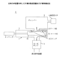
図3は、弁装置1(ゲートバルブ)を設けた半導体製造装置2(ドライエッチャー)を示している。半導体製造装置2は、大略するとゲートバルブ1,チャンバー3,真空圧センサ4,ターボポンプ5,及び図示しない真空排気装置等により構成されている。
【0005】
チャンバー3は下部にゲート部6が形成されており、このゲート部6にはゲートバルブ1が配設されている。また、ゲートバルブ1の下部にはターボポンプ5及び真空排気装置(以下、これらを合わせていう場合には真空系という)が配設されており、ゲートバルブ1が開弁した状態においてゲート部6を介してチャンバー3に対して真空引きを行い、チャンバー3内を所定の真空度とする構成とされている。
【0006】
また、チャンバー3には真空圧センサ4が配設されており、チャンバー3内の真空圧を検出しうる構成となっている。そして、ドライエッチングが行なわれる半導体基板は、上記構成とされたチャンバー3内に装着され、図示しない導入配管より反応ガス(腐食性ガス)が導入されることにより所定のエッチング処理が実施される。
【0007】
また、ゲートバルブ1は、ハウジング7内に図中矢印A1,A2方向に移動する弁体10を有しており、この弁体10をシリンダー8で駆動するとによりゲート部6を開閉する構成とされている。また、弁体10にはシール部材としてOリング9が配設されており、弁体10が閉弁位置(図3に示す状態)に移動した状態においてOリング9はゲート部6をシールし、これによりチャンバー3は真空系に対して気密に画成された状態となる。
【0008】
このように、ゲート部6がOリング9によりシールされた状態においてハウジング7内に反応ガス(腐食性ガス)が供給されると、Oリング9は反応ガス(腐食性ガス)に触れた状態となり、経時的にOリング9には劣化が発生する。ここで、Oリング9に劣化が発生した場合に半導体製造装置2に発生する不都合について説明する。
【0009】
ゲートバルブ1がゲート部6を閉弁する時として、チャンバー3のリーク検査時が挙げられる。このチャンバー3のリーク検査は、チャンバー3内を真空系を用いて所定の真空圧にした後、ゲートバルブ1によりゲート部6を閉弁し、その後に真空圧センサ4によりチャンバー3内の圧力変化を検出する。
【0010】
仮にチャンバー3にリークがある場合には、真空圧センサ4により検出される圧力は上昇するため、これによりチャンバー3にリークが発生しているか否かを検出することができる。尚、このリーク検査時においても真空系は駆動した状態を維持しており、検査終了した後に直ちにチャンバー3の真空引き処理が行ないうる構成とされている。
【0011】
ところで、Oリング9が劣化しリークが発生していると、ゲートバルブ1は完全にゲート部6を閉弁していないため、真空系が発生する負圧によりチャンバー3が真空引きされてしまい、本来のチャンバー3の外部リークを検出できなくなってしまう。
【0012】
よって、実際にはチャンバー3に外部リークがあるにも拘わらず、Oリング9の劣化に起因して正常であると誤判定された場合には、ドライエッチング処理時において所定の真空度が実現できず、また外部リークにより大気等の不純物が混入するため、加工処理される半導体基板に異常が発生するおそれがある。
【0013】
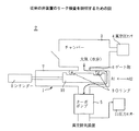
また、半導体基板をチャンバー3に出し入れする時や、後述する従来のゲートバルブ1のリーク検査時(後に詳述する)においては、図4に示されるように、ゲートバルブ1を閉弁した状態でチャンバー3を大気開放する。しかるに、この大気開放状態では、チャンバー3内には水分を含む大気が入り込む。更に、大気開放状態においても真空系は駆動した状態を維持している。
【0014】
従って、Oリング9が劣化しリークが発生していると、水分を含む大気がターボポンプ5等の真空系に侵入し真空系を構成する装置を腐食させたり、またリーク量が多い場合にはターボポンプ5を破損してしまうおそれがある。
よって、半導体基板に対する加工処理を精度良く行なうと共に、真空系の損傷を防止するためには、Oリング9の劣化を早期にかつ正確に検出することが重要となる。
【0015】
ここで、従来実施されていたOリング9の劣化を検出する方法の一例を図4を用いて説明する。
従来実施されていたOリング9の劣化検出方法は、ターボポンプ5の排出側配管に圧力センサ11を取り付けると共に、ゲートバルブ1を閉弁した状態でチャンバー3を大気開放する。そして、この状態において真空系を駆動して真空引きを実施する。いま、Oリング9が劣化しゲートバルブ1にリークが発生している場合を想定すると、大気はOリング9を介して真空系側にリークするため、圧力センサ11の検出値は上昇する。よって、圧力センサ11の検出値の変動を見ることによりOリング9の劣化を検出することが行なわれていた。
【0016】
また、他のOリング9の劣化検出方法としては、半導体製造装置2を停止させた上でゲートバルブ1を分解してOリング9を取り外し、検査者が直接目視によりOリング9の劣化を判定する検査が行なわれていた。
【0017】
【発明が解決しようとする課題】
しかるに、上記したチャンバー3を大気圧にしてOリング9の劣化を検出する方法は、半導体基板に対する加工処理を停止させる必要があり、加工処理の効率が低下してしまう。また、チャンバー3を大気開放する際、チャンバー3内に流入する空気により塵が舞い上がってしまい、検査終了後に半導体基板をチャンバー3に装着した際にこの塵が半導体基板に付着するおそれがある。更に、検査を行ない再び半導体製造装置2を復旧させるまでに約1〜2時間程度の長い時間が必要となり、半導体装置の製造効率を考慮すると日常的にOリング9の劣化検出を行なうことができなかった。
【0018】
また、ゲートバルブ1を分解してOリング9を取り外して点検を行なう方法では、ゲートバルブ1の分解作業に半日〜1日程度の時間が必要となり、これを日常点検するのは非現実的であり、この点検方法は殆ど実施されていなかった。
本発明は上記の点に鑑みてなされたものであり、弁装置のリーク検出を容易かつ正確に行ないうる弁装置のリーク検出装置及びリーク検出方法を提供することを目的とする。
【0019】
【課題を解決するための手段】
上記課題を解決するために本発明では、次の手段を講じたことを特徴とするものである。
請求項1記載の発明では、
シール部を有する弁体をハウジング内の開弁位置と閉弁位置との間で移動させることによりゲート部の開閉を行なう構成とされた弁装置のリーク検出装置において、
前記弁体が前記ハウジング内の開弁位置にある時、前記シール部に対し圧力媒体を印加する加圧装置と、
前記シール部に印加する圧力媒体の圧力を検出する圧力検出装置と、
前記圧力検出装置が検出する前記圧力媒体の圧力に基づき、前記シール部のリークを検出するリーク検出手段とを設けたことを特徴とするものである。
【0020】
また、請求項2記載の発明では、
前記請求項1記載の弁装置のリーク検出装置において、
前記シール部に印加した前記圧力媒体の放出量を制御する放出量制御手段を設けたことを特徴とするものである。
【0021】
また、請求項3記載の発明では、
前記請求項1または2記載の弁装置のリーク検出装置において、
前記ゲート部を半導体製造装置のチャンバーに設けると共に、前記圧力検出装置を前記チャンバーに配設したことを特徴とするものである。
【0022】
また、請求項4記載の発明では、
シール部を有する弁体をハウジング内の開弁位置と閉弁位置との間で移動させることによりゲート部の開閉を行なう構成とされた弁装置のリーク検出方法において、
前記弁体を前記ハウジング内の開弁位置に移動させ、
次に前記弁体に形成されたシール部に対し圧力媒体を印加し、
前記圧力媒体の圧力を検出すると共に、検出される圧力変化に基づき前記シール部のリークを検出することを特徴とするものである。
【0023】
上記した手段は、次のように作用する。
請求項1記載の発明によれば、
加圧装置は、弁装置の弁体がハウジング内の開弁位置にある時、シール部に対して圧力媒体を印加する。また、圧力検出装置は、シール部に印加される圧力媒体の圧力を検出する。更に、リーク検出手段は圧力検出装置が検出する圧力媒体の圧力に基づきシール部のリークを検出する。
【0024】
ところで、シール部にリークが発生している場合には、圧力媒体はシール部を通過するためシール部の上流側における圧力媒体の圧力は低下する。この圧力媒体の圧力低下は、圧力検出装置により検出することができる。
従って、リーク検出手段は圧力検出装置が出力する圧力媒体の圧力変化に基づき、シール部にリークが発生しているか否かを検出することができる。また、この検査は人手を必要としないため、弁装置のリーク検出を自動的に行なうことが可能となる。
【0025】
更に、シール部のリーク検出は、弁体がハウジング内の開弁位置にある状態で行なわれるため、弁装置が取り付けられた装置・機器を稼働した状態を維持しつつリーク検出を行なうことができる。従って、弁装置のリーク検査を日常的に実施することが可能となり、弁装置が配設される装置・機器の稼働効率を向上させることができる。
【0026】
また、請求項2記載の発明によれば、
シール部に印加した圧力媒体の放出量を制御する放出量制御手段を設けたことにより、リーク検出処理の終了直後に弁体を移動させる必要が生じても、圧力媒体は放出量制御手段によりその放出量が制御されるため、圧力媒体が急激に弁体に印加されることを防止することができる。これにより、リーク検出処理の終了直後における弁体の移動を円滑に行なうことができる。
【0027】
また、請求項3記載の発明によれば、
ゲート部を半導体製造装置のチャンバーに設けると共に、圧力検出装置をチャンバーに配設したことにより、通常時(リーク検出を行なわない時)において圧力検出装置をチャンバー内の圧力検出センサとして用いることができ、またリーク検出時においては圧力検出装置をリーク検出用センサとして用いることができる。このように、圧力検出装置に二つのセンサ機能を持たせることにより、半導体製造装置の構成を簡単化することができる。
【0028】
また、請求項4記載の発明によれば、
弁装置のリーク検出を行なうに際し、先ず弁体をハウジング内の開弁位置に移動させ、次に弁体に形成されたシール部に対し圧力媒体を印加し、続いて圧力媒体の圧力を検出すると共に検出される圧力変化に基づきシール部のリークを検出することにより、人手を必要とすることなく弁装置のリーク検出を実施できるため、リーク検出の自動化を図ることができ、よってリーク検出を容易に行なうことが可能となる。
【0029】
【発明の実施の形態】
次に、本発明の実施の形態について図面と共に説明する。
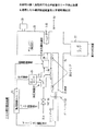
図1は本発明の第1実施例である弁装置のリーク検出装置を適用した半導体製造装置20を示す概略構成図である。半導体製造装置20は、大略すると弁装置であるゲートバルブ21,加圧装置22,チャンバー23,圧力検出装置となる圧力センサ24,リーク検出手段となる監視制御ユニット25,放出量制御手段となる放出量制御弁26,ターボポンプ27,及び図示しない真空排気装置等により構成されている。
【0030】
チャンバー23は下部にゲート部28が形成されており、ゲートバルブ21はこのゲート部28に配設されている。また、ゲートバルブ21の下部にはターボポンプ27及び真空排気装置(以下、これらを合わせていう場合には真空系という)が配設されており、ゲートバルブ21が開弁した状態においてゲート部28を介してチャンバー23に対して真空引きを行い、チャンバー23内を所定の真空度とする構成とされている。また、チャンバー23には真空圧センサ29が配設されており、チャンバー23内の真空圧を検出しうる構成となっている。
【0031】
加工処理(例えばドライエッチング)が行なわれる半導体基板は、上記構成とされたチャンバー23内に装着され、図示しない導入配管より反応ガス(腐食性ガス)が供給されることにより所定のエッチング処理が実施される。
また、ゲートバルブ21は、ハウジング30内に図中矢印A1,A2方向に移動する弁体31を有しており、この弁体31をシリンダー32で駆動することによりゲート部28を開閉する構成とされている。このシリンダー32は、例えばエアシリンダーであり、後述する監視制御ユニット25からゲートバルブ開閉命令が送信されることにより弁体31開弁方向(A1方向)または閉弁方向(A2方向)に選択的に移動させる構成となっている。
【0032】
一方、上記した弁体31にはシール部材としてOリング33が配設されており、弁体31が閉弁位置に移動した状態においてOリング33はゲート部28をシール(閉弁)し、これによりチャンバー23は真空系に対して気密に画成された状態となる。尚、図1は弁体31が開弁位置にある状態を示している。
【0033】
加圧装置22は、大略すると圧力媒体供給装置(図示せず),バルブ34,供給配管35等により構成されている。圧力媒体供給装置は圧力媒体を圧送する装置であり、例えばピストンポンプ等の使用が考えられる。また、本実施例では圧力媒体としてヘリウム(He)ガスを用いている。圧力媒体供給装置で加圧されたHeガスは、供給配管35に向け圧送される。
【0034】
また、圧力媒体供給装置と供給配管35との間にはバルブ34が配設されている。このバルブ34は例えば電磁弁として構成されており、監視制御ユニット25から送信されるバルブ開閉信号により開閉する構成とされている。従って、バルブ34が監視制御ユニット25からの信号に基づき開弁することにより、Heガスは供給配管35に流入する。
【0035】
供給配管35は、一端部が前記のようにバルブ34に接続されると共に、他端部が前記したゲートバルブ21のハウジング30に接続されている。また、供給配管35がハウジング30に接続される位置は、弁体31が開弁位置にある状態において、一対のOリング33の間位置となるよう構成されている。
【0036】
従って、バルブ34が開弁し高圧のHeガスが供給配管35に流入すると、このHeガスは一対のOリング33の間位置に供給されることとなる。ハウジング30と弁体31との間には微小な隙間が形成されており、この隙間が一対のOリング33によりシールされた構成とされているため、供給された高圧のHeガスは一対のOリング33に印加されることとなる。
【0037】
一方、供給配管35には圧力センサ24が配設されている。この圧力センサ24は供給配管35内の圧力を検出する構成とされており、また圧力センサ24で検出された供給配管内圧力は圧力信号として監視制御ユニット25に送信される構成とされている。
【0038】
更に、供給配管35にはゲート部28と接続された放出配管36が接続されており、この放出配管36の途中には放出制御弁26が配設されている。放出配管36は供給配管35に供給された高圧のHeガスを放出する(逃がす)ために設けられており、放出制御弁26が開弁することにより供給配管35内のHeガスは放出配管36を通りゲート部28に放出される。
【0039】
上記した放出制御弁26は監視制御ユニット25に接続されており、監視制御ユニット25から送信される流量制御信号によりその開弁度が制御される構成とされている。尚、上記構成において、放出配管36の接続位置はゲート部28に限定されるものではなく、他の部位(例えばターボポンプ27の下流側)に配設してもよい。
【0040】
一方、監視制御ユニット25はマイクロコンピュータにより構成されており、前記した放出量制御弁26,シリンダー32,及びバルブ34の駆動制御を行なうと共に、圧力センサ24から供給される圧力信号に基づきOリング33にリークが発生しているか否か(即ち、Oリング33に劣化が発生しているか否か)を検出する処理(以下、この処理をリーク検出処理という)を行なう。
【0041】
以下、本実施例において監視制御ユニット25が実施するリーク検出処理について説明する。
半導体製造装置20がリーク検出処理モードとなると、監視制御ユニット25は、先ずゲートバルブ21の弁体31が閉弁状態にある場合にはシリンダー32を駆動して弁体31を開弁方向(A1方向)に移動させる。尚、半導体製造装置20がリーク検出処理モードとなった時点で弁体31が開弁状態にある場合には、この処理は行なわない。
【0042】
弁体31が開弁位置にあることを確認すると、続いて監視制御ユニット25はバルブ34を開弁すると共に、放出量制御弁26を閉弁する。これにより、圧力媒体供給装置から高圧のHeガスはバルブ34を介して供給配管35に供給され、更に前記したようにハウジング30と弁体31との間の隙間を介して一対のOリング33に印加される。この際、放出量制御弁26は閉弁されているため、Heガスが放出配管36を通りゲート部28に放出されることはない。
【0043】
この弁体31が開弁された状態において、監視制御ユニット25は圧力センサ24から送信される圧力信号に基づき、供給配管35内の圧力変化を監視する。いま、シール部となるOリング33が劣化することによりリークが発生している場合には、高圧のHeガス(圧力媒体)はOリング33を通過し、このためOリング33の上流側に位置する供給配管35内の圧力は低下する。この供給配管35内におけるHeガスの圧力低下は、圧力センサ24により検出することができる。
【0044】
従って、リーク検出手段となる監視制御ユニット25は圧力センサ24から送信されてくるHeガスの圧力変化に基づき、Oリング33にリークが発生しているか否かを検出することができる。また、この検査は人手を必要としないため、弁装置のリーク検出を自動的にかつ正確に行なうことが可能となる。
【0045】
また、上記のようにリーク検出処理は弁体31がハウジング30内の開弁位置にある状態で行なわれる。この弁体31が開弁した状態は、チャンバー23内で半導体基板に対し加工処理を行なう状態と同じである。
更に、ターボポンプ27及び真空排気装置により構成される真空系は、リーク検出処理には影響を及ぼさないため、稼働させた状態を維持することができる。即ち、本実施例の構成では、チャンバー23内で半導体基板に対し加工処理を実施しつつ、Oリング33に対するリーク検出処理を実施することができる。
【0046】
これにより、半導体基板に対する加工処理を停止することなくOリング33に対するリーク検出処理を実施できるため、リーク検出処理を日常的に実施することが可能となり、ゲートバルブ21が配設される半導体製造装置20の稼働効率を向上させることができる。
【0047】
続いて、リーク検出処理が終了した後の動作について説明する。いま、リーク検出処理が終了した直後に弁体31を移動させる必要が生じたとする。リーク検出処理が終了することにより、監視制御ユニット25から送信されるバルブ開閉信号によりバルブ34は閉弁するが、リーク検出処理の終了直後では弁体31にはまだ高圧のHeガスが作用している。従って、この状態において弁体31を移動させると高圧のHeガスにより弁体31が急激に移動し、ゲートバルブ21を損傷するおそれがある。更に、大量のHeガスによりターボポンプ27を損傷するおそれがある。
【0048】
しかるに本実施例では、リーク検出処理が終了した後に監視制御ユニット25は放出量制御弁26を開弁制御することによりHeガスをゲート部28に排出する。よって、高圧のHeガスが急激に弁体31に印加されることを防止することができ、これによりリーク検出処理の終了直後における弁体31の移動を円滑に行なうことができる。
【0049】
また、Heガスをゲート部28に排出することにより、チャンバー23内の圧力が急激に変化するおそれがあるが、監視制御ユニット25はチャンバー23内の圧力が急激に変化しないように放出量制御弁26を開弁制御する処理も行なう。尚、弁体31に印加されるHeガスの圧力が高い間は、監視制御ユニット25からシリンダー32に対しゲートバルブ閉弁信号は送信されないようロックされる構成とされており、ゲートバルブ21やターボポンプ27の損傷を確実に防止できる構成とされている。
【0050】
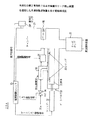
続いて、本発明の第2実施例について説明する。
図2は本発明の第2実施例であるリーク検出装置を適用した半導体製造装置20Aを示している。尚、図2において、図1に示した第1実施例に係るリーク検出装置を適用した半導体製造装置20と同一構成については同一符号を附してその説明を省略する。
【0051】
前記した第1実施例に係るリーク検出装置を適用した半導体製造装置20は、チャンバー23内の真空度を検出するセンサとして真空圧センサ29を設けると共に、リーク検出処理を行なうのに用いる圧力センサ24を別個設けた構成としていた。
【0052】
しかるに、真空圧センサ29も圧力センサであるため、真空圧センサ29をリーク検出処理を行なう圧力センサとして用いることも可能である。そこで、本実施例では真空圧センサ29Aをリーク検出処理を行なう圧力センサとしても用いる構成としたことを特徴とするものである。このため、真空圧センサ29Aが検出する真空圧は、真空圧信号として監視制御ユニット25に送信される構成となっている。
【0053】
ここで、リーク検出処理においてOリング33に高圧のHeガスを印加した際、Oリング33にリークが発生した場合を想定する。Oリング33にリークが発生していると、高圧のHeガスはOリング33を通過してゲート部28に供給され、これによりチャンバー23内の圧力は上昇する現象が発生する。
【0054】
このチャンバー23内の圧力上昇は、チャンバー23に配設された真空圧センサ29Aにより検出することができる。従って、監視制御ユニット25は、真空圧センサ29Aから送信される真空圧信号に基づきチャンバー23内の圧力変化を監視することにより、Oリング33にリークが発生しているか否かを判定することができる。
【0055】
上記のように、本実施例の構成によれば、通常時(リーク検出処理を行なわない時)においては、真空圧センサ29Aを本来的なチャンバー23内の圧力検出センサとして用いることができ、またリーク検出処理時においては真空圧センサ29Aをリーク検出用センサとして用いることができる。このように、真空圧センサ29Aに二つのセンサ機能を持たせることにより、半導体製造装置20Aの構成を簡単化することができる。
【0056】
尚、上記した実施例においては、ゲートバルブ21を半導体製造装置20,20Aのゲート部28に配設した構成を示したが、半導体基板の搬送通路の途中に配設されるゲートバルブについても本願発明を適用することができる。
また、本実施例では圧力媒体としてHeガスを用いたが、圧力媒体はHeガスに限定されるものではなく、例えは窒素(N2 ) ガス,アルゴン(Ar)ガス等の他の不活性ガスを用いることも可能である。
【0057】
更に、本実施例ではシール部となるOリング33に高圧媒体を印加する構成としたが、逆にOリング33に高い負圧を印加し、この負圧の変化を検出することによりリークの検出を行なう構成とすることも可能である。
【0058】
【発明の効果】
上述の如く本発明によれば、次に述べる種々の効果を実現することができる。請求項1または請求項4記載の発明によれば、リーク検出手段は圧力検出装置が出力する圧力媒体の圧力変化に基づき、シール部にリークが発生しているか否かを検出することができる、またこの検査は人手を必要としないため、弁装置のリーク検出を自動的に行なうことが可能となる。
【0059】
また、シール部のリーク検出は、弁体がハウジング内の開弁位置にある状態で行なわれるため、弁装置が取り付けられた装置・機器を稼働した状態を維持しつつリーク検出を行なうことができ、従って弁装置のリーク検査を日常的に実施することが可能となり、弁装置が配設される装置・機器の稼働効率を向上させることができる。
【0060】
また、請求項2記載の発明によれば、リーク検出処理の終了直後に弁体を移動させる必要が生じても、圧力媒体は放出量制御手段によりその放出量が制御されるため、圧力媒体が急激に弁体に印加されることを防止することができ、これによりリーク検出処理の終了直後における弁体の移動を円滑に行なうことが可能となる。
【0061】
また、請求項3記載の発明によれば、通常時(リーク検出を行なわない時)において圧力検出装置をチャンバー内の圧力検出センサとして用いることができ、またリーク検出時においては圧力検出装置をリーク検出用センサとして用いることができるため、圧力検出装置は二つのセンサ機能を持つこととなり、リーク検出機能を有する半導体製造装置の構成を簡単化することができる。
【図面の簡単な説明】
【図1】本発明の第1実施例である弁装置のリーク検出装置を適用した半導体製造装置を示す概略構成図である。
【図2】本発明の第2実施例である弁装置のリーク検出装置を適用した半導体製造装置を示す概略構成図である。
【図3】従来の弁装置を有した半導体製造装置を示す概略構成図である。
【図4】従来の弁装置のリーク検査を説明するための図である。
【符号の説明】
20,20A 半導体製造装置
21 ゲートバルブ
22 加圧装置
23 チャンバー
24 圧力センサ
25 監視制御ユニット
26 放出量制御弁
27 ターボポンプ
28 ゲート部
29,29A 真空圧センサ
30 ハウジング
31 弁体
32 シリンダー
33 Oリング
34 バルブ
35 供給配管
36 放出配管[0001]
TECHNICAL FIELD OF THE INVENTION
The present invention relates to a leak detection device and a leak detection method for a valve device, and more particularly to a leak detection device and a leak detection method for a valve device that detects leak of a seal portion using a pressure medium.
[0002]
For example, a vacuum processing apparatus is connected to a semiconductor manufacturing apparatus such as a dry etcher, and a valve unit (gate valve) for defining each apparatus in an airtight manner is provided at a gate portion where the semiconductor manufacturing apparatus and the vacuum processing apparatus are connected. ) Is arranged. In general, the gate valve uses an O-ring as a sealing member, and the gate portion is sealed by the O-ring when the gate valve is closed, whereby each device is air-tightly defined.
[0003]
On the other hand, since a semiconductor manufacturing apparatus uses a corrosive gas in a semiconductor manufacturing process, it is known that the O-ring is deteriorated by the corrosive gas. When the O-ring is deteriorated, a leak of corrosive gas occurs when the gate valve is closed, which may cause an abnormality in a manufactured semiconductor integrated circuit. Therefore, it is necessary to reliably detect the deterioration of the O-ring (seal member) and minimize the influence of the leak of the corrosive gas.
[0004]
[Prior art]
FIG. 3 shows a semiconductor manufacturing apparatus 2 (dry etcher) provided with a valve device 1 (gate valve). The
[0005]
The
[0006]
Further, a vacuum pressure sensor 4 is provided in the
[0007]
In addition, the gate valve 1 has a
[0008]
As described above, when the reaction gas (corrosive gas) is supplied into the
[0009]
The time when the gate valve 1 closes the gate portion 6 includes a time when a leak test of the
[0010]
If there is a leak in the
[0011]
By the way, if the O-ring 9 is deteriorated and a leak is generated, the
[0012]
Therefore, in spite of the fact that the
[0013]
In addition, when the semiconductor substrate is taken in and out of the
[0014]
Therefore, if the O-ring 9 has deteriorated and a leak has occurred, the atmosphere containing moisture enters the vacuum system such as the
Therefore, it is important to detect the deterioration of the O-ring 9 early and accurately in order to perform the processing on the semiconductor substrate with high accuracy and to prevent the vacuum system from being damaged.
[0015]
Here, an example of a conventional method for detecting the deterioration of the O-ring 9 will be described with reference to FIG.
In the method of detecting deterioration of the O-ring 9 which has been conventionally performed, the pressure sensor 11 is attached to the discharge pipe of the
[0016]
As another method for detecting deterioration of the O-ring 9, the
[0017]
[Problems to be solved by the invention]
However, in the method of detecting the deterioration of the O-ring 9 by setting the
[0018]
Further, in the method of disassembling the gate valve 1 and removing the O-ring 9 for inspection, the disassembling operation of the gate valve 1 requires about half a day to one day, and it is impractical to perform a daily inspection. Yes, this inspection method was hardly implemented.
The present invention has been made in view of the above points, and an object of the present invention is to provide a leak detection device and a leak detection method for a valve device that can easily and accurately detect a leak from the valve device.
[0019]
[Means for Solving the Problems]
In order to solve the above problems, the present invention is characterized by taking the following means.
In the invention according to claim 1,
In a leak detection device of a valve device configured to open and close a gate portion by moving a valve body having a seal portion between a valve opening position and a valve closing position in a housing,
A pressurizing device for applying a pressure medium to the seal portion when the valve element is at an open position in the housing;
A pressure detector for detecting the pressure of the pressure medium applied to the seal portion,
And a leak detecting means for detecting a leak of the seal portion based on a pressure of the pressure medium detected by the pressure detecting device.
[0020]
In the invention according to
The leak detection device for a valve device according to claim 1,
A discharge amount control means for controlling a discharge amount of the pressure medium applied to the seal portion is provided.
[0021]
In the invention according to
The leak detection device for a valve device according to
The gate unit is provided in a chamber of a semiconductor manufacturing apparatus, and the pressure detecting device is provided in the chamber.
[0022]
In the invention according to claim 4,
In a leak detection method of a valve device configured to open and close a gate by moving a valve body having a seal portion between a valve opening position and a valve closing position in a housing,
Moving the valve body to a valve opening position in the housing;
Next, a pressure medium is applied to a seal portion formed on the valve body,
The pressure of the pressure medium is detected, and the leak of the seal portion is detected based on the detected pressure change.
[0023]
The above-described means works as follows.
According to the first aspect of the present invention,
The pressurizing device applies a pressure medium to the seal portion when the valve body of the valve device is in the valve open position in the housing. Further, the pressure detecting device detects the pressure of the pressure medium applied to the seal portion. Further, the leak detecting means detects a leak of the seal portion based on the pressure of the pressure medium detected by the pressure detecting device.
[0024]
By the way, when a leak occurs in the seal portion, the pressure medium passes through the seal portion, so that the pressure of the pressure medium on the upstream side of the seal portion decreases. This pressure drop of the pressure medium can be detected by a pressure detection device.
Therefore, the leak detecting means can detect whether or not a leak has occurred in the seal portion based on the pressure change of the pressure medium output by the pressure detecting device. In addition, since this inspection does not require any manpower, it is possible to automatically detect the leak of the valve device.
[0025]
Furthermore, since the leak detection of the seal portion is performed in a state where the valve body is in the valve open position in the housing, it is possible to perform the leak detection while maintaining a state in which the device / equipment to which the valve device is attached is operated. . Therefore, it is possible to carry out a leak test of the valve device on a daily basis, and it is possible to improve the operation efficiency of the device / equipment provided with the valve device.
[0026]
According to the second aspect of the present invention,
With the provision of the release amount control means for controlling the release amount of the pressure medium applied to the seal portion, even if the valve element needs to be moved immediately after the end of the leak detection processing, the pressure medium is controlled by the release amount control means. Since the release amount is controlled, it is possible to prevent the pressure medium from being rapidly applied to the valve body. Thereby, the movement of the valve element immediately after the end of the leak detection processing can be performed smoothly.
[0027]
According to the third aspect of the present invention,
By providing the gate part in the chamber of the semiconductor manufacturing equipment and arranging the pressure detection device in the chamber, the pressure detection device can be used as a pressure detection sensor in the chamber during normal times (when leak detection is not performed). In detecting a leak, the pressure detecting device can be used as a leak detecting sensor. As described above, by providing the pressure detecting device with two sensor functions, the configuration of the semiconductor manufacturing apparatus can be simplified.
[0028]
According to the fourth aspect of the present invention,
In performing the leak detection of the valve device, first, the valve body is moved to the valve opening position in the housing, and then the pressure medium is applied to the seal formed on the valve body, and then the pressure of the pressure medium is detected. By detecting the leak of the seal portion based on the pressure change detected together with the pressure, the leak detection of the valve device can be performed without requiring any manual operation, so that the leak detection can be automated, and the leak detection can be easily performed. Can be performed.
[0029]
BEST MODE FOR CARRYING OUT THE INVENTION
Next, embodiments of the present invention will be described with reference to the drawings.
FIG. 1 is a schematic configuration diagram showing a
[0030]
The chamber 23 has a gate portion 28 formed at a lower portion, and the gate valve 21 is disposed in the gate portion 28. Further, a
[0031]
A semiconductor substrate on which processing (eg, dry etching) is performed is mounted in the chamber 23 having the above-described configuration, and a predetermined etching process is performed by supplying a reactive gas (corrosive gas) from an introduction pipe (not shown). Is done.
Further, the gate valve 21 has a valve element 31 that moves in the directions of arrows A1 and A2 in the housing 30 in the housing 30, and the gate element 28 is opened and closed by driving the valve element 31 with the cylinder 32. Have been. The cylinder 32 is, for example, an air cylinder, and selectively receives a gate valve opening / closing command from a
[0032]
On the other hand, an O-ring 33 is disposed as a sealing member on the above-described valve element 31. When the valve element 31 is moved to the valve closing position, the O-ring 33 seals (closes) the gate portion 28. Thus, the chamber 23 is airtightly defined with respect to the vacuum system. FIG. 1 shows a state where the valve element 31 is at the valve opening position.
[0033]
The pressurizing device 22 includes a pressure medium supply device (not shown), a valve 34, a supply pipe 35, and the like. The pressure medium supply device is a device that pressure-feeds the pressure medium, and for example, a piston pump or the like can be used. In this embodiment, helium (He) gas is used as the pressure medium. The He gas pressurized by the pressure medium supply device is sent to the supply pipe 35 by pressure.
[0034]
Further, a valve 34 is provided between the pressure medium supply device and the supply pipe 35. The valve 34 is configured as, for example, an electromagnetic valve, and is configured to open and close according to a valve opening and closing signal transmitted from the
[0035]
The supply pipe 35 has one end connected to the valve 34 as described above, and the other end connected to the housing 30 of the gate valve 21 described above. Further, the position where the supply pipe 35 is connected to the housing 30 is configured to be between the pair of O-rings 33 when the valve element 31 is in the valve opening position.
[0036]
Therefore, when the valve 34 is opened and high-pressure He gas flows into the supply pipe 35, this He gas is supplied to a position between the pair of O-rings 33. Since a small gap is formed between the housing 30 and the valve element 31 and the gap is sealed by a pair of O-rings 33, the supplied high-pressure He gas is supplied by a pair of O-rings. This is applied to the ring 33.
[0037]
On the other hand, the
[0038]
Further, a discharge pipe 36 connected to the gate 28 is connected to the supply pipe 35, and a discharge control valve 26 is provided in the middle of the discharge pipe 36. The discharge pipe 36 is provided for discharging (releasing) the high-pressure He gas supplied to the supply pipe 35, and the He gas in the supply pipe 35 causes the discharge pipe 36 to be released by opening the discharge control valve 26. It is discharged to the gate 28.
[0039]
The above-mentioned discharge control valve 26 is connected to the
[0040]
On the other hand, the
[0041]
Hereinafter, a leak detection process performed by the
When the
[0042]
After confirming that the valve element 31 is at the valve opening position, the
[0043]
In a state where the valve element 31 is opened, the
[0044]
Therefore, the
[0045]
Further, as described above, the leak detection processing is performed in a state where the valve element 31 is in the valve opening position in the housing 30. The state in which the valve element 31 is opened is the same as the state in which the semiconductor substrate is processed in the chamber 23.
Further, the vacuum system constituted by the
[0046]
Accordingly, the leak detection process can be performed on the O-ring 33 without stopping the processing process on the semiconductor substrate, so that the leak detection process can be performed on a daily basis, and the semiconductor manufacturing apparatus in which the gate valve 21 is provided. 20 can be improved in operating efficiency.
[0047]
Subsequently, an operation after the end of the leak detection processing will be described. Now, it is assumed that it is necessary to move the valve element 31 immediately after the end of the leak detection processing. When the leak detection process is completed, the valve 34 is closed by the valve opening / closing signal transmitted from the
[0048]
However, in this embodiment, after the leak detection processing is completed, the
[0049]
Further, the discharge of the He gas to the gate unit 28 may cause a sudden change in the pressure in the chamber 23. However, the
[0050]
Next, a second embodiment of the present invention will be described.
FIG. 2 shows a semiconductor manufacturing apparatus 20A to which a leak detection device according to a second embodiment of the present invention is applied. In FIG. 2, the same components as those of the
[0051]
The
[0052]
However, since the vacuum pressure sensor 29 is also a pressure sensor, it is possible to use the vacuum pressure sensor 29 as a pressure sensor for performing a leak detection process. Therefore, the present embodiment is characterized in that the vacuum pressure sensor 29A is also used as a pressure sensor for performing a leak detection process. Therefore, the vacuum pressure detected by the vacuum pressure sensor 29A is transmitted to the
[0053]
Here, it is assumed that a leak occurs in the O-ring 33 when a high-pressure He gas is applied to the O-ring 33 in the leak detection processing. If a leak occurs in the O-ring 33, the high-pressure He gas is supplied to the gate section 28 through the O-ring 33, whereby a phenomenon occurs in which the pressure in the chamber 23 increases.
[0054]
The pressure increase in the chamber 23 can be detected by the vacuum pressure sensor 29A provided in the chamber 23. Therefore, the
[0055]
As described above, according to the configuration of the present embodiment, the vacuum pressure sensor 29A can be used as an original pressure detection sensor in the chamber 23 during normal times (when leak detection processing is not performed). During the leak detection processing, the vacuum pressure sensor 29A can be used as a leak detection sensor. As described above, by providing the vacuum pressure sensor 29A with two sensor functions, the configuration of the semiconductor manufacturing apparatus 20A can be simplified.
[0056]
In the above-described embodiment, the configuration in which the gate valve 21 is provided in the gate portion 28 of the
In this embodiment, He gas is used as the pressure medium. However, the pressure medium is not limited to He gas. 2 It is also possible to use other inert gases such as gas and argon (Ar) gas.
[0057]
Further, in this embodiment, the high-pressure medium is applied to the O-ring 33 serving as the seal portion. However, a high negative pressure is applied to the O-ring 33 and the change in the negative pressure is detected to detect the leak. Is also possible.
[0058]
【The invention's effect】
As described above, according to the present invention, the following various effects can be realized. According to the first or fourth aspect of the present invention, the leak detecting means can detect whether or not a leak has occurred in the seal portion based on a change in pressure of the pressure medium output by the pressure detecting device. In addition, since this inspection does not require any manpower, it is possible to automatically detect the leak of the valve device.
[0059]
In addition, since the leak detection of the seal portion is performed in a state where the valve body is in the valve open position in the housing, the leak detection can be performed while maintaining a state in which the device / equipment to which the valve device is attached is operated. Therefore, it is possible to carry out a leak test on the valve device on a daily basis, and it is possible to improve the operating efficiency of the device / equipment provided with the valve device.
[0060]
According to the second aspect of the present invention, even if it is necessary to move the valve immediately after the end of the leak detection processing, the discharge amount of the pressure medium is controlled by the discharge amount control means. It is possible to prevent the voltage from being suddenly applied to the valve element, thereby making it possible to smoothly move the valve element immediately after the end of the leak detection processing.
[0061]
According to the third aspect of the present invention, the pressure detection device can be used as a pressure detection sensor in the chamber during normal times (when leak detection is not performed), and when the leak is detected, the pressure detection device leaks. Since the pressure detection device can be used as a detection sensor, the pressure detection device has two sensor functions, and the configuration of a semiconductor manufacturing apparatus having a leak detection function can be simplified.
[Brief description of the drawings]
FIG. 1 is a schematic configuration diagram showing a semiconductor manufacturing apparatus to which a leak detection device for a valve device according to a first embodiment of the present invention is applied.
FIG. 2 is a schematic configuration diagram showing a semiconductor manufacturing apparatus to which a leak detection device for a valve device according to a second embodiment of the present invention is applied.
FIG. 3 is a schematic configuration diagram showing a semiconductor manufacturing apparatus having a conventional valve device.
FIG. 4 is a view for explaining a leak test of a conventional valve device.
[Explanation of symbols]
20,20A Semiconductor manufacturing equipment
21 Gate valve
22 Pressurizing device
23 chamber
24 Pressure sensor
25 Monitoring and control unit
26 Emission control valve
27 turbo pump
28 Gate
29,29A Vacuum pressure sensor
30 Housing
31 Valve
32 cylinders
33 O-ring
34 valve
35 Supply piping
36 Release piping
Claims (4)
前記弁体が前記ハウジング内の開弁位置にある時、前記シール部に対し圧力媒体を印加する加圧装置と、
前記シール部に印加する圧力媒体の圧力を検出する圧力検出装置と、
前記圧力検出装置が検出する前記圧力媒体の圧力に基づき、前記シール部のリークを検出するリーク検出手段と
を具備することを特徴とする弁装置のリーク検出装置。In a leak detection device of a valve device configured to open and close a gate portion by moving a valve body having a seal portion between a valve opening position and a valve closing position in a housing,
A pressurizing device for applying a pressure medium to the seal portion when the valve element is at an open position in the housing;
A pressure detector for detecting the pressure of the pressure medium applied to the seal portion,
A leak detecting device for a valve device, comprising: leak detecting means for detecting a leak of the seal portion based on a pressure of the pressure medium detected by the pressure detecting device.
前記シール部に印加した前記圧力媒体の放出量を制御する放出量制御手段を設けたことを特徴とする弁装置のリーク検出装置。The leak detection device for a valve device according to claim 1,
A leak detecting device for a valve device, further comprising a discharge amount control means for controlling a discharge amount of the pressure medium applied to the seal portion.
前記弁体を前記ハウジング内の開弁位置に移動させ、
次に前記弁体に形成されたシール部に対し圧力媒体を印加し、
前記圧力媒体の圧力を検出すると共に、検出される圧力変化に基づき前記シール部のリークを検出することを特徴とする弁装置のリーク検出方法。In a leak detection method of a valve device configured to open and close a gate by moving a valve body having a seal portion between a valve opening position and a valve closing position in a housing,
Moving the valve body to a valve opening position in the housing;
Next, a pressure medium is applied to a seal portion formed on the valve body,
A method for detecting a leak in a valve device, comprising: detecting a pressure of the pressure medium; and detecting a leak of the seal portion based on a detected pressure change.
Priority Applications (1)
| Application Number | Priority Date | Filing Date | Title |
|---|---|---|---|
| JP21749396A JP3588198B2 (en) | 1996-08-19 | 1996-08-19 | Leak detecting device and leak detecting method for valve device |
Applications Claiming Priority (1)
| Application Number | Priority Date | Filing Date | Title |
|---|---|---|---|
| JP21749396A JP3588198B2 (en) | 1996-08-19 | 1996-08-19 | Leak detecting device and leak detecting method for valve device |
Publications (2)
| Publication Number | Publication Date |
|---|---|
| JPH1062289A JPH1062289A (en) | 1998-03-06 |
| JP3588198B2 true JP3588198B2 (en) | 2004-11-10 |
Family
ID=16705109
Family Applications (1)
| Application Number | Title | Priority Date | Filing Date |
|---|---|---|---|
| JP21749396A Expired - Fee Related JP3588198B2 (en) | 1996-08-19 | 1996-08-19 | Leak detecting device and leak detecting method for valve device |
Country Status (1)
| Country | Link |
|---|---|
| JP (1) | JP3588198B2 (en) |
Families Citing this family (1)
| Publication number | Priority date | Publication date | Assignee | Title |
|---|---|---|---|---|
| CN113944802A (en) * | 2021-11-11 | 2022-01-18 | 安徽省屯溪高压阀门有限公司 | Leakage self-alarming valve |
-
1996
- 1996-08-19 JP JP21749396A patent/JP3588198B2/en not_active Expired - Fee Related
Also Published As
| Publication number | Publication date |
|---|---|
| JPH1062289A (en) | 1998-03-06 |
Similar Documents
| Publication | Publication Date | Title |
|---|---|---|
| US6820465B2 (en) | Apparatus for on-line detection of leaky valves | |
| EP4168767B1 (en) | Apparatus and method for automatic leak detection | |
| US7165443B2 (en) | Vacuum leakage detecting device for use in semiconductor manufacturing system | |
| JPH11214489A (en) | Vacuum processing equipment | |
| JP2006177810A (en) | Inspection device and inspection method | |
| JP3588198B2 (en) | Leak detecting device and leak detecting method for valve device | |
| KR100572700B1 (en) | A method and apparatus for detecting a vacuum leakage | |
| KR101664192B1 (en) | Apparatus and method for treating substrate | |
| EP0877246A2 (en) | In situ monitoring of contaminants in semiconductor processing chambers | |
| JP3149226B2 (en) | Leak detection device | |
| JPH11153508A (en) | Helium leakage detector apparatus for vacuum apparatus | |
| JP2004251798A (en) | High pressure air leak detection method | |
| JPH018714Y2 (en) | ||
| US12046456B2 (en) | Inspection method of plasma processing apparatus | |
| JP2826479B2 (en) | Gas supply device and operation method thereof | |
| JPH11241971A (en) | Leak test equipment | |
| KR200338202Y1 (en) | An apparatus for detecting a vacuum leakage | |
| JPH10213516A (en) | Helium leak detector | |
| CN223526322U (en) | Integrated special gas cylinder detection cabinet | |
| JP2001021436A (en) | Leak inspection apparatus and leakage inspection method | |
| JP2007095728A (en) | Device manufacturing apparatus and leak check method | |
| JP3385536B2 (en) | Gas supply source | |
| JP2024083171A (en) | Small amount gas supply method, small amount gas supply device, leak inspection method, and leak inspection device | |
| CN210071221U (en) | Assembly for measuring pressure of vacuum chamber and substrate processing equipment | |
| JPH07171374A (en) | Method for operating exhaust valve |
Legal Events
| Date | Code | Title | Description |
|---|---|---|---|
| A977 | Report on retrieval |
Free format text: JAPANESE INTERMEDIATE CODE: A971007 Effective date: 20040421 |
|
| A131 | Notification of reasons for refusal |
Free format text: JAPANESE INTERMEDIATE CODE: A131 Effective date: 20040518 |
|
| TRDD | Decision of grant or rejection written | ||
| A01 | Written decision to grant a patent or to grant a registration (utility model) |
Free format text: JAPANESE INTERMEDIATE CODE: A01 Effective date: 20040810 |
|
| A61 | First payment of annual fees (during grant procedure) |
Free format text: JAPANESE INTERMEDIATE CODE: A61 Effective date: 20040812 |
|
| R150 | Certificate of patent or registration of utility model |
Free format text: JAPANESE INTERMEDIATE CODE: R150 |
|
| LAPS | Cancellation because of no payment of annual fees |