JP3585196B2 - Crawler belt type vehicle suspension system - Google Patents
Crawler belt type vehicle suspension system Download PDFInfo
- Publication number
- JP3585196B2 JP3585196B2 JP20079196A JP20079196A JP3585196B2 JP 3585196 B2 JP3585196 B2 JP 3585196B2 JP 20079196 A JP20079196 A JP 20079196A JP 20079196 A JP20079196 A JP 20079196A JP 3585196 B2 JP3585196 B2 JP 3585196B2
- Authority
- JP
- Japan
- Prior art keywords
- crawler belt
- wheel
- vehicle body
- rear wheel
- vehicle
- Prior art date
- Legal status (The legal status is an assumption and is not a legal conclusion. Google has not performed a legal analysis and makes no representation as to the accuracy of the status listed.)
- Expired - Fee Related
Links
Images


Landscapes
- Body Structure For Vehicles (AREA)
Description
【0001】
【発明の属する技術分野】
本発明は、前輪をタイヤ、後輪をクローラとしたクローラベルト式車両(いわゆる、ハーフクローラ車)の改良に関する。
【0002】
【従来の技術】
従来、ハーフクローラ車として、例えば特開昭59−164270号公報「履帯を有する四輪駆動車」の技術がある。
上記技術は、その公報の第1図によれば、四輪駆動車2(番号は公報に記載されたものを引用した。以下同じ。)の車体前部に前輪3を取付け、車体後部にタイヤ付き後輪4及びタイヤ付き遊動輪5を取付け、これら後輪4及び遊動輪5にゴム製の履帯6を掛け渡したものである。
【0003】
【発明が解決しようとする課題】
ところで、このような一般のハーフクローラ車は、車体と車輪との間をスプリング、ダンパ等の懸架装置で連結している。このようなハーフクローラ車が斜面を横切って走行した場合、すなわち、車体を左右に傾けた場合に、前記懸架装置より上の部分が谷側へ移動する。このため、車体の重量バランスが偏り、操縦性に影響がでる。
【0004】
また、一般に、クローラベルトは、サイドドラッグ抵抗(横滑り抵抗)が大きいので、サイドスリップが発生しにくい。サイドドラッグ抵抗は、ハーフクローラ車を旋回した際のブレーキ要因となり、ハーフクローラ車の旋回性を低下させる(前輪で発生した旋回モーメントにとって、ブレーキ要因となる。)。しかし、ハーフクローラ車であっても、旋回性は高い方がよい。
【0005】
そこで本発明の目的は、(1)斜面での車体の安定性を高めることで、操縦性が良いハーフクローラ車を提供すること、(2)旋回性を高めたハーフクローラ車を提供することにある。
【0006】
【課題を解決するための手段】
上記目的を達成するための請求項1は、車体前部に空気入りタイヤ付き前輪を取付け、車体後部にリヤ懸架装置を介して中間輪及び後輪を取付け、これら中間輪及び後輪にクローラベルトを掛け渡したクローラベルト式車両において、車体から後方へスイングアームを上下揺動可能に延出し、このスイングアームのスイング基端部は、車体との揺動点の位置となっており、スイングアームの先端部は、後輪用駆動軸を取付けるとともに、前方へ延出させ且つ上下揺動可能に1対のサブビームの基部を取付け、これらサブビームの先端部に中間輪用支軸を取付け、これら中間輪用支軸に中間輪を取付け、前記後輪用駆動軸に駆動輪としての後輪を取付け、これら中間輪及び後輪を、前記車体に対して上下動のみ可能で車幅方向に移動不能に取付けたことを特徴とする。
【0007】
(1)後輪を、車体に対して上下動のみ可能で車幅方向に移動不能に取付けたので、斜面を横切って走行した場合でも、車体の重心は車幅方向に移動しない。そのため、車体の重量バランスが偏らず安定性が良く、操縦性に影響がでない。
【0008】
(2)後輪を、車体に対して上下動のみ可能で車幅方向に移動不能に取付けたので、クローラベルト式車両の旋回時に発生する横向加速度(一般に「横G」という。)によって、クローラベルトにサイドドラッグ力(横滑り力)が発生する。その結果、クローラベルトにサイドスリップが発生しやすい。このため、サイドスリップを積極的に利用することができるので、旋回性を高めることができる。
【0009】
(3)スイングアームの先端部に1対のサブビームを上下揺動可能に取付け、これらのサブビームを前方に延出し、その先端部に中間輪用支軸を取付け、これら中間輪用支軸に中間輪を取付けたので、1対の中間輪は互いに独立して上下動可能であり、路面の凹凸に対応して円滑に上下動することができる。このため、凹凸の多い路面でクローラベルト式車両を走行した場合に、各中間輪が上下動するので、車体は緩慢に上下動することになる。従って、路面追従性が良いので乗り心地が良く、また、車体に対して、左右の後輪を同時に上下動可能に取付けた場合であっても、車体の急激な上下動を抑制できる。
【0010】
(4)後輪を駆動輪としたので、クローラベルトを駆動した際に、それの反力により、クローラには中間輪を持上げようとするモーメントが生じる。その結果、クローラは、走行方向にある雪や泥などの堆積した所を容易に乗越えることができる。このため、クローラベルト式車両の走破性が高まる。
【0011】
請求項2は、前記サブビームは、クローラベルトの張力調整をするために走行方向に伸縮可能に構成したことを特徴とする。
【0012】
簡単な構成で、クローラベルトの張力調整をすることができる。
【0013】
請求項3は、前記左のサブビームと右のサブビームとを、前記中間輪用支軸の取付け位置近傍にて、揺動可能なクロスロッドで結合したことを特徴とする。
【0014】
クローラベルト式車両を旋回した際などに、中間輪の下方で、クローラベルトにサイドドラッグ力(横滑り力)が発生する。その結果、左右のサブビームに横方向の曲げモーメントが生じる。これに対して、左のサブビームと右のサブビームとをクロスロッドにて結合したので、左右のサブビームの曲げ剛性が高い。
また、左右のサブビームは、基部をスイングアームに取付け、先端部同士をクロスロッドで結合したものである。このため、後輪と中間輪のホイールアライメント(キャスター、キャンバー、トーインと称する車輪整列)が確保でき、直進安定性、ステアリング応答性を高めることができる。
【0015】
【発明の実施の形態】
本発明の実施の形態を添付図面に基づいて以下に説明する。なお、図面は符号の向きに見るものとする。
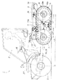
図1は本発明に係るクローラベルト式車両の側面図であり、クローラベルト式車両1は前輪をタイヤ、後輪をクローラとした、いわゆる、ハーフクローラ車である。
【0016】
詳しくは、クローラベルト式車両1は、前部のキャビン2と後部の荷台3とを備えた車体フレーム(車体)4に、駆動輪としての前輪5と、駆動輪としての後輪6と、これら前・後輪5,6の間に介在した遊転輪としての中間輪7と、これら後・中間輪6,7との間に介在したイコライザ8とを左右に取付け、後輪6と中間輪7とに(車輪間に)クローラベルト9を掛け渡すことでクローラを構成した、4輪駆動・クローラ式車両である。
【0017】
前輪5、後輪6及び中間輪7はゴム製空気入りタイヤを備え、このタイヤは、バルーンタイヤである。前輪5は、後輪6及び中間輪7よりも大径である。
クローラベルト9は、ゴム材などの可撓性材料からなり、内周面に且つ幅方向両側に、タイヤのショルダ部に対する多数のサイドガイド部9a…(…は複数を示す。以下同じ。)を起設し、接地面9bに所定の凹凸パターン(ラグパターン)を形成したものである。
車体フレーム4は、後部にトランスミッション11a付きエンジン11を取付けたものである。
【0018】
ところで、クローラベルト式車両1は、前輪5のタイヤの接地面圧を0.1〜0.15kg/cm2の範囲に設定し、一方、クローラベルト9の接地面圧を0.04〜0.05kg/cm2の範囲に設定したものである。
【0019】
雪上等の軟弱地において、クローラベルト式車両1を走行時に、前輪5のタイヤの接地面圧が0.1kg/cm2より小さいと、前輪タイヤの沈み深さが過小になる。沈み深さが過小であると、雪や泥などに沈んだ部分の側面からの投影面積が小さいので、操舵抵抗も小さくなる。このため、操舵抵抗が小さくなり過ぎて、軟弱地で十分に操縦性を確保しにくくなる。
また、前輪5のタイヤの接地面圧が0.15kg/cm2より大きいと、前輪タイヤの沈み深さが過大になる。沈み深さが過大であると、雪や泥などの抵抗が大きくなるので、旋回性を高めにくくなり、特に、新雪でしかも未踏の地では顕著となる。
【0020】
一方、クローラベルト9の接地面圧が0.04kg/cm2より小さいと、クローラベルト9の沈み深さが過小になり、また、接地面圧が0.05kg/cm2より大きいと、クローラベルト9の沈み深さが過大になる。クローラベルト9の沈み深さが過小であったり過大であると、走行路面の走行抵抗が大きくなるので、走破性を高めにくくなり、特に、新雪でしかも未踏の地では顕著となる。
【0021】
従って、前輪5のタイヤの接地面圧及びクローラベルト9の接地面圧は、上記の範囲に設定することが好ましい。
接地面圧をこのような範囲に設定するために、トランスミッション11a付きエンジン11は、全体をクローラベルト9の前端と後端との間に配設したものである。
エンジン11は、後輪6の中心と中間輪7の中心との間に配設することが好ましく、更には、エンジン11のクランクシャフトの中心Cから後輪6の中心までの第1の距離L1と、クランクシャフトの中心Cから中間輪7の中心までの第2の距離L2との比率を、約2:1に設定することが最も好ましい。
また、前記第1の距離L1は、前輪5と後輪6との中心間距離(第3の距離としてのホイールベース)L3の約30%の割合にすることが好ましい。
更に、側面視で(この図において)、クローラベルト9のループ内に、トランスミッション11a付きエンジン11の一部を配設した。
【0022】
なお、荷台3は車体フレーム4の後部上部に一体に取付けた構成とした。14はマフラ、15は乗員用シート、16はステアリングハンドル、17はチェンジレバー、18はアクセルペダル、19はブレーキペダル、21はサイドブレーキ、22はフロントフェンダである。
【0023】
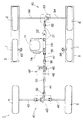
図2は本発明に係るクローラベルト式車両の平面図であり、キャビン2及び荷台3を外した姿を示す。なお、荷台3はこの図の想像線にて示す。
車体フレーム4は、前部にフロントサスペンション25と操舵装置30と前輪用駆動装置40とを備え、後部に後輪用駆動装置50とリヤ懸架装置60とを備える。
【0024】
操舵装置30は、想像線にて示すステアリングハンドル16の操舵力を伝達するためのタイロッド31、このタイロッド31の両端のタイロッドエンド32,32に連結したナックルアーム33,33、これらナックルアーム33,33と前輪5,5の支軸5a,5aとを連結したキングピン34,34等からなる。
リヤ懸架装置60は、後輪6及び中間輪7を車体フレーム4(車体)に対して上下動のみ可能で車幅方向に移動不能に取付けたものである。リヤ懸架装置60の詳細は後述する。
【0025】
次に、前輪用駆動装置40及び後輪用駆動装置50を説明する。
図3は本発明に係る前・後輪用駆動装置の概念図である。
クローラベルト式車両1は、エンジン11の動力をトランスミッション11aを介して、前輪5,5及び後輪6,6に伝達する前・後輪駆動式である。
前輪用駆動装置40は、トランスミッション11aの出力取出部11bから前方へ延出した前部推進軸41と、この前部推進軸41に連結した前輪用差動装置42と、この前輪用差動装置42と前輪5,5の支軸5a,5a(図2参照)との間に連結した左右の前輪用駆動軸43,43とからなる。
また、前輪用駆動装置40は、エンジン11と前輪用駆動軸43,43との間にギヤボックス44を介在したものである。詳しくは、ギヤボックス44は、前部推進軸41の途中に介在し、前輪5を変速する変速機構45及び前輪5への動力伝達を入り・切りするクラッチ機構46を内蔵したものである。
【0026】
後輪用駆動装置50は、トランスミッション11aの出力取出部11bから後方へ延出した後部推進軸51と、この後部推進軸51に自在継手52を介して連結した後輪用差動装置53と、この後輪用差動装置53に連結した左右の後輪用駆動軸54,54とからなり、これら後輪用駆動軸54,54の両端部に後輪6,6を連結した構成である。
56…は等速継手である。
【0027】
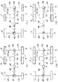
次に、上記構成の前輪用駆動装置40及び後輪用駆動装置50の作用を、図4に基づき説明する。
図4(a)〜(d)は本発明に係る前・後輪用駆動装置の作用図である。
(a)は、前輪5,5を小径タイヤとし、クローラベルト9,9を装着した場合を示す。クラッチ機構46は「入」状態にある。この場合は、変速機構45を第I段に設定して、前輪5,5の小径タイヤの速度とクローラベルト9,9の速度とを一致させる。その結果、クローラベルト式車両1は、前・後輪駆動による円滑な走行ができる。
【0028】
(b)は、前輪5,5を大径タイヤとし、クローラベルト9,9を装着した場合を示す。クラッチ機構46は「入」状態にある。この場合は、変速機構45を第II段に設定して、前輪5,5の大径タイヤの速度とクローラベルト9,9の速度とを一致させる。その結果、クローラベルト式車両1は、前・後輪駆動による円滑な走行ができる。
【0029】
(c)は、前輪5,5を大径タイヤとし、クローラベルト9,9を外した場合を示す。クラッチ機構46は「入」状態にある。この場合は、変速機構45を第III段に設定して、前輪5,5の大径タイヤの速度と後輪6,6のタイヤの速度とを一致させる。その結果、クローラベルト式車両1は、前・後輪駆動による円滑な走行ができる。
【0030】
(d)は、上記(b)において、クラッチ機構46を「切」状態にした場合を示す。この場合には、クローラベルト式車両1は、後輪駆動による走行ができる。
このように、クローラベルト式車両1は、クローラベルト9,9の着脱にかかわらず、また、前輪5,5のタイヤ径にかかわらず、円滑に走行可能である。
【0031】
次に、リヤ懸架装置60を説明する。
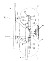
図5は本発明に係るリヤ懸架装置の斜視図であり、リヤ懸架装置60は、車体フレーム(車体)4から後方へスイングアーム61を上下揺動可能に延出し、このスイングアーム61の先端部に、後輪用駆動軸54,54を取付けるとともに、前方へ延出させ且つ上下揺動可能に1対のサブビーム63,63の基部を取付け、これらサブビーム63,63の先端部に中間輪用支軸66,66を取付け、これら中間輪用支軸66,66に中間輪7,7(図2参照)を取付け、前記後輪用駆動軸54,54に駆動輪としての後輪6,6(図2参照)を取付けたものである。
【0032】
詳しくは、スイングアーム61は、車幅方向に延出して車体フレーム4に回動可能に取付けた支持ビーム部61aと、この支持ビーム部61aから車体後方へ延出した3つのアーム部(左アーム部61b、中央アーム部61c、右アーム部61d)とからなる、平面視略E字状アームである。
中央アーム部61cは、先端部に後輪用差動装置53のハウジング53aを取付けた筒体であり、後輪用差動装置53に連結する後部推進軸51を挿通したものである。なお、後部推進軸51は、スイングアーム61の揺動点の位置に自在継手52を設けてあるので、スイングアーム61とともに上下揺動可能である。後輪用差動装置53のハウジング53aは、車幅方向両側に延出する連結筒部62,62を取付けたものであり、これらハウジング53aと両側の連結筒部62,62とからなる連結体は、3つのアーム部61b〜61dの先端部に掛け渡したビームとなる。
【0033】
連結筒部62,62は、後輪用駆動軸54,54を挿通し、しかも、これら後輪用駆動軸54,54を回転可能に且つ軸方向移動不能に取付けたものである。このため、スイングアーム61は先端部に、連結筒部62,62を介して、後輪用駆動軸54,54を回転可能に且つ軸方向移動不能に取付けたことになる。従って、後輪用駆動軸54,54に取付けた後輪6,6は、車体フレーム(車体)4に対して上下動のみ可能で車幅方向に移動不能である。
また、後輪用駆動軸54,54は、車体フレーム4に対して平行状態を維持しつつ上下揺動可能である。このため、左右の後輪6,6は、互いに連動して同時に上下動可能である。
なお、後輪用差動装置53及び後輪用駆動軸54,54と左右の連結筒部62,62とは、同心上に配設したものである。
【0034】
左右の連結筒部62,62は、車幅方向両端に1対のサブビーム63,63の基部を取付けたものであり、これらサブビーム63,63は前方へ延出したものである。
ところで、サブビーム63は、クローラベルト9(図1参照)の張力調整をするために、走行方向に伸縮可能に構成したものである。
詳しくは、サブビーム63は、連結筒部62,62に上下揺動可能に取付けたビーム部材64と、このビーム部材64の先端部側面に前後スライド可能に取付けたビーム延長部65とからなり、ビーム延長部65に中間輪支軸66を取付けたものである。そして、中間輪用支軸66,66は、中間輪7,7を取付けたものである。
従って、中間輪7,7は、車体フレーム(車体)4に対して上下動のみ可能で車幅方向に移動不能である。
【0035】
ビーム部材64とビーム延長部65とは、ターンバックル67にてスライド調整可能に連結したものであり、従って、クローラベルト9の張力調整作業を、ターンバックル67で行うことになる。64aはビーム延長部65を案内するガイド部、64b…はビーム部材64にビーム延長部65を止めるボルトである。
左のサブビーム63と右のサブビーム63とは、中間輪用支軸66,66の取付け位置近傍にて、揺動可能なクロスロッド68で結合したものである。
61e,61eは補強部材、69は後方ガードパイプである。
【0036】
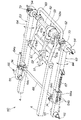
図6は本発明に係るリヤ懸架装置の側面図であり、リヤ懸架装置60は、車体後部としての荷台3又は車体フレーム4に、第1・第2オイルダンパ(ショックアブソーバ)71,72を介してサブビーム63の基端部及び先端部近傍を懸架したものである。
詳しくは、第1オイルダンパ71は、ブラケット73を介して左右の後輪用駆動軸54,54の近傍を左右2箇所懸架し、第2オイルダンパ72は、ブラケット74を介してビーム部材64の先端部(中間輪用支軸66の近傍)を左右2箇所懸架したものである。
なお、第1オイルダンパ71は、左右の後輪用駆動軸54,54の近傍を1箇所懸架したものでもよい。
【0037】
図7は本発明に係るクロスロッド取付け部分の分解斜視図である。
クロスロッド68は、ビーム部材64の延出方向に貫通した結合環68a,68aを車幅方向両端に取付け、これら結合環68a,68aにダンパ機能を有するゴムブッシュ75,75を圧入したものである。そして、クロスロッド68の端部は、ゴムブッシュ75,75を介して、ビーム部材64,64のブラケット64c,64cに上下揺動可能にボルト76,76にて結合する。
【0038】
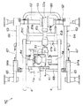
図8は本発明に係るリヤ懸架装置の平面図であり、車体フレーム4の後部に且つ車幅方向略中央に、ブラケット4a,4aを介してトランスミッション11a付きエンジン11を取付けた姿を示す。
【0039】
次に、上記構成のリヤ懸架装置60の作用を説明する。
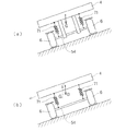
図9(a),(b)は本発明に係るリヤ懸架装置の作用図であり、(a)は本発明を示し、(b)は比較例を示す。
(b)の示す比較例のハーフクローラ車は、車体4と後輪6,6との間をオイルダンパ71,71で連結している。このようなハーフクローラ車が斜面を横切って走行した場合、すなわち、車体4を左右に傾けた場合に、オイルダンパ71,71より上の部分が谷側へ移動するので、車体重心Gが谷側へ移動する(G→G0)。このため、車体4の重量バランスが偏り、操縦性に影響がでる。
これに対して、(a)に示す本発明のハーフクローラ車は、後輪6,6を、車体に対して上下動のみ可能で車幅方向に移動不能に取付けたので、斜面を横切って走行した場合に、車体4の重心Gが車幅方向に移動しない。このため、車体4の重量バランスが偏らず安定性が良く、操縦性に影響がでない。
【0040】
一方、図2において、後輪6,6を、車体4に対して上下動のみ可能で車幅方向に移動不能に取付けたので、クローラベルト式車両1の旋回時に発生する横向加速度(一般に「横G」という。)によって、クローラベルト9,9にサイドドラッグ力(横滑り力)が発生する。その結果、クローラベルト9,9にサイドスリップが発生しやすい。このため、サイドスリップを積極的に利用することができるので、旋回性を高めることができる。
【0041】
また、スイングアーム31の先端部に1対のサブビーム63,63を上下揺動可能に取付け、これらのサブビーム63,63を前方に延出し、その先端部に中間輪用支軸66,66を取付け、これら中間輪用支軸66,66に中間輪7,7を取付けたので、1対の中間輪7,7は互いに独立して上下動可能であり、路面の凹凸に対応して円滑に上下動することができる。このため、凹凸の多い路面でクローラベルト式車両1を走行した場合に、各中間輪7,7が上下動するので、車体4は緩慢に上下動することになる。従って、路面追従性が良いので乗り心地が良く、また、車体4に対して、左右の後輪6,6を同時に上下動可能に取付けた場合であっても、車体4の急激な上下動を抑制できる。
【0042】
更に、後輪6,6を駆動輪としたので、クローラベルト9,9を駆動した際に、それの反力により、クローラには中間輪を持上げようとするモーメントが生じる。その結果、クローラは、走行方向にある雪や泥などの堆積した所を容易に乗越えることができる。このため、クローラベルト式車両1の走破性が高まる。
【0043】
なお、上記実施の形態において、変速機構45やクラッチ機構46は、エンジン11と前輪用駆動軸13,13との間、又はエンジン11と後輪用駆動軸54,54との間に介在したものであればよい。
また、変速機構45の変速段数は、用途に応じて任意に設定すればよい。
更に、クラッチ機構46の取付けは任意である。
更にまた、後輪6及び中間輪7は、車体フレーム(車体)4に対して上下動のみ可能で車幅方向に移動不能であればよい。例えば、スイングアーム61の先端部に、後輪用駆動軸54,54を上下動のみ可能で車幅方向に移動不能に直接取付け、これら後輪用駆動軸54,54に後輪6,6を取付けたものでもよい。
サブビーム63は、クローラベルト9の張力調整をするために走行方向に伸縮可能な構成であればよく、ビーム部材64とビーム延長部65とターンバックル67との組合せに限定するものではない。
【0044】
【発明の効果】
本発明は上記構成により次の効果を発揮する。
請求項1は、車体前部に空気入りタイヤ付き前輪を取付け、車体後部にリヤ懸架装置を介して中間輪及び後輪を取付け、これら中間輪及び後輪にクローラベルトを掛け渡したクローラベルト式車両において、車体から後方へスイングアームを上下揺動可能に延出し、このスイングアームのスイング基端部は、車体との揺動点の位置となっており、スイングアームの先端部は、後輪用駆動軸を取付けるとともに、前方へ延出させ且つ上下揺動可能に1対のサブビームの基部を取付け、これらサブビームの先端部に中間輪用支軸を取付け、これら中間輪用支軸に中間輪を取付け、前記後輪用駆動軸に駆動輪としての後輪を取付け、これら中間輪及び後輪を、前記車体に対して上下動のみ可能で車幅方向に移動不能に取付けたことを特徴とする。
【0045】
(1)後輪を、車体に対して上下動のみ可能で車幅方向に移動不能に取付けたので、斜面を横切って走行した場合でも、車体の重心は車幅方向に移動しない。そのため、車体の重量バランスが偏らず安定性が良く、操縦性に影響がでない。
【0046】
(2)後輪を、車体に対して上下動のみ可能で車幅方向に移動不能に取付けたので、クローラベルト式車両の旋回時に発生する横向加速度によって、クローラベルトにサイドドラッグ力が発生する。その結果、クローラベルトにサイドスリップが発生しやすい。このため、サイドスリップを積極的に利用することができるので、旋回性を高めることができる。
【0047】
(3)スイングアームの先端部に1対のサブビームを上下揺動可能に取付け、これらのサブビームを前方に延出し、その先端部に中間輪用支軸を取付け、これら中間輪用支軸に中間輪を取付けたので、1対の中間輪は互いに独立して上下動可能であり、路面の凹凸に対応して円滑に上下動することができる。このため、凹凸の多い路面でクローラベルト式車両を走行した場合に、各中間輪が上下動するので、車体は緩慢に上下動することになる。従って、路面追従性が良いので乗り心地が良く、また、車体に対して、左右の後輪を同時に上下動可能に取付けた場合であっても、車体の急激な上下動を抑制できる。
【0048】
(4)後輪を駆動輪としたので、クローラベルトを駆動した際に、それの反力により、クローラには中間輪を持上げようとするモーメントが生じる。その結果、クローラは、走行方向にある雪や泥などの堆積した所を容易に乗越えることができる。このため、クローラベルト式車両の走破性が高まる。
【0049】
請求項2は、サブビームは、クローラベルトの張力調整をするために走行方向に伸縮可能に構成したことを特徴とする。
【0050】
簡単な構成で、クローラベルトの張力調整をすることができる。
【0051】
請求項3は、前記左のサブビームと右のサブビームとを、前記中間輪用支軸の取付け位置近傍にて、揺動可能なクロスロッドで結合したことを特徴とする。
【0052】
クローラベルト式車両を旋回した際などに、中間輪の下方で、クローラベルトにサイドドラッグ力(横滑り力)が発生する。その結果、左右のサブビームに横方向の曲げモーメントが生じる。これに対して、左のサブビームと右のサブビームとをクロスロッドにて結合したので、左右のサブビームの曲げ剛性が高い。
また、左右のサブビームは、基部をスイングアームに取付け、先端部同士をクロスロッドで結合したものである。このため、後輪と中間輪のホイールアライメント(キャスター、キャンバー、トーインと称する車輪整列)が確保でき、直進安定性、ステアリング応答性を高めることができる。
【図面の簡単な説明】
【図1】本発明に係るクローラベルト式車両の側面図
【図2】本発明に係るクローラベルト式車両の平面図
【図3】本発明に係る前・後輪用駆動装置の概念図
【図4】本発明に係る前・後輪用駆動装置の作用図
【図5】本発明に係るリヤ懸架装置の斜視図
【図6】本発明に係るリヤ懸架装置の側面図
【図7】本発明に係るクロスロッド取付け部分の分解斜視図
【図8】本発明に係るリヤ懸架装置の平面図
【図9】本発明に係るリヤ懸架装置の作用図
【符号の説明】
1…クローラベルト式車両、5…前輪、6…後輪、7…中間輪、9…クローラベルト、11…エンジン、11a…トランスミッション、43…前輪用駆動軸、44…ギヤボックス、45…変速機構、46…クラッチ機構、54…後輪用駆動軸、60…リヤ懸架装置、61…スイングアーム、63…サブビーム、64…ビーム部材、65…ビーム延長部、66…中間輪支軸、67…ターンバックル、68…クロスロッド。[0001]
TECHNICAL FIELD OF THE INVENTION
The present invention relates to an improvement in a crawler belt type vehicle (a so-called half crawler vehicle) using a front wheel as a tire and a rear wheel as a crawler.
[0002]
[Prior art]
2. Description of the Related Art Conventionally, as a half crawler vehicle, for example, there is a technology disclosed in Japanese Patent Application Laid-Open No. Sho 59-164270 entitled "Four-wheel drive vehicle having crawler tracks".
According to FIG. 1 of the publication, the above-mentioned technology attaches a
[0003]
[Problems to be solved by the invention]
Incidentally, in such a general half-crawler vehicle, the vehicle body and the wheels are connected by a suspension device such as a spring or a damper. When such a half-crawler vehicle travels across a slope, that is, when the vehicle body is tilted left and right, a portion above the suspension device moves to the valley side. For this reason, the weight balance of the vehicle body is biased, and the maneuverability is affected.
[0004]
In general, the crawler belt has a large side drag resistance (side slip resistance), so that the side slip hardly occurs. The side drag resistance becomes a braking factor when turning the half crawler wheel, and lowers the turning performance of the half crawler wheel (it becomes a braking factor for the turning moment generated at the front wheels). However, even for a half-crawler vehicle, it is preferable that the turning performance be high.
[0005]
Therefore, an object of the present invention is to (1) provide a half-crawler vehicle with good maneuverability by improving the stability of the vehicle body on a slope, and (2) provide a half-crawler vehicle with improved turning performance. is there.
[0006]
[Means for Solving the Problems]
In order to achieve the above object, a front wheel with a pneumatic tire is mounted on a front portion of a vehicle body, an intermediate wheel and a rear wheel are mounted on a rear portion of the vehicle body via a rear suspension device, and a crawler belt is mounted on the intermediate wheel and the rear wheel. In the crawler belt type vehicle, the swing arm extends up and down from the vehicle The swing base end of the swing arm is the position of the swing point with the vehicle body, Swing arm tip Is Attaching the drive shaft for the rear wheel, attaching the base of a pair of sub-beams extending forward and swinging up and down, attaching the support for the intermediate wheel to the tip of these sub-beams, A rear wheel as a drive wheel is mounted on the rear wheel drive shaft, and the intermediate wheel and the rear wheel are mounted such that they can only move up and down with respect to the vehicle body but cannot move in the vehicle width direction. It is characterized by.
[0007]
(1) Since the rear wheel is mounted so that it can only move up and down with respect to the vehicle body and cannot move in the vehicle width direction, the center of gravity of the vehicle body does not move in the vehicle width direction even when traveling across a slope. Therefore, the weight balance of the vehicle body is not biased, the stability is good, and the maneuverability is not affected.
[0008]
(2) Since the rear wheel is mounted so that it can only move up and down with respect to the vehicle body and cannot move in the vehicle width direction, the crawler belt is driven by lateral acceleration (generally referred to as "lateral G") generated when the crawler belt type vehicle turns. Side drag force (side slip force) is generated on the belt. As a result, a side slip easily occurs in the crawler belt. For this reason, the side slip can be positively used, so that the turning property can be improved.
[0009]
(3) At the tip of the swing arm, a pair of sub-beams are mounted so as to be able to swing up and down, these sub-beams are extended forward, and a support shaft for an intermediate wheel is mounted at the tip thereof, and the support shaft for the intermediate wheel is attached to the intermediate shaft. Since the wheels are attached, the pair of intermediate wheels can move up and down independently of each other, and can move up and down smoothly according to the unevenness of the road surface. For this reason, when the crawler belt type vehicle travels on a road surface with a lot of unevenness, each intermediate wheel moves up and down, so that the vehicle body slowly moves up and down. Therefore, the vehicle has good road surface followability, so that the ride comfort is good, and even when the left and right rear wheels are attached to the vehicle body so as to be able to move up and down at the same time, it is possible to suppress sudden vertical movement of the vehicle body.
[0010]
(4) Since the rear wheels are the driving wheels, when the crawler belt is driven, a reaction force of the crawler belt generates a moment to lift the intermediate wheel on the crawler belt. As a result, the crawler can easily get over a place where snow, mud, and the like are accumulated in the traveling direction. Therefore, the traveling performance of the crawler belt type vehicle is enhanced.
[0011]
A second aspect of the present invention is characterized in that the sub-beam is configured to be extendable and contractible in a traveling direction in order to adjust a tension of a crawler belt.
[0012]
The tension of the crawler belt can be adjusted with a simple configuration.
[0013]
A third aspect of the present invention is characterized in that the left sub-beam and the right sub-beam are connected to each other by a swingable cross rod near a mounting position of the intermediate wheel support shaft.
[0014]
When a crawler belt type vehicle is turned, a side drag force (side slip force) is generated in the crawler belt below the intermediate wheel. As a result, a lateral bending moment is generated in the left and right sub-beams. On the other hand, since the left sub-beam and the right sub-beam are connected by the cross rod, the bending rigidity of the left and right sub-beams is high.
The left and right sub-beams have their bases attached to a swing arm and their ends joined by a cross rod. For this reason, wheel alignment (wheel alignment called casters, cambers, toe-in) between the rear wheel and the intermediate wheel can be ensured, and the straight running stability and steering response can be enhanced.
[0015]
BEST MODE FOR CARRYING OUT THE INVENTION
Embodiments of the present invention will be described below with reference to the accompanying drawings. The drawings should be viewed in the direction of reference numerals.
FIG. 1 is a side view of a crawler belt type vehicle according to the present invention. The crawler
[0016]
Specifically, the crawler
[0017]
The
The
The
[0018]
By the way, the crawler
[0019]
When traveling the crawler
The contact pressure of the tire of the
[0020]
On the other hand, the contact pressure of the
[0021]
Therefore, it is preferable that the contact surface pressure of the tire of the
In order to set the contact surface pressure in such a range, the
The
Further, the first distance L 1 Is the center-to-center distance between the
Further, a part of the
[0022]
The
[0023]
FIG. 2 is a plan view of the crawler belt type vehicle according to the present invention, showing a state where the
The
[0024]
The
In the
[0025]
Next, the front
FIG. 3 is a conceptual diagram of a front and rear wheel drive device according to the present invention.
The crawler
The front
The front
[0026]
The rear
56 are constant velocity joints.
[0027]
Next, the operation of the front
FIGS. 4A to 4D are operation diagrams of the front and rear wheel drive device according to the present invention.
(A) shows the case where the
[0028]
(B) shows the case where the
[0029]
(C) shows a case where the
[0030]
(D) shows a case where the
As described above, the crawler
[0031]
Next, the
FIG. 5 is a perspective view of a rear suspension device according to the present invention. In the
[0032]
Specifically, the
The
[0033]
The connecting
The rear
The rear wheel
[0034]
The left and right connecting
By the way, the sub-beam 63 is configured to be extendable and contractible in the traveling direction in order to adjust the tension of the crawler belt 9 (see FIG. 1).
More specifically, the sub-beam 63 is composed of a
Therefore, the
[0035]
The
The
61e and 61e are reinforcing members, and 69 is a rear guard pipe.
[0036]
FIG. 6 is a side view of a rear suspension device according to the present invention. The
More specifically, the
Note that the
[0037]
FIG. 7 is an exploded perspective view of a cross rod mounting portion according to the present invention.
The
[0038]
FIG. 8 is a plan view of the rear suspension device according to the present invention, and shows a state in which the
[0039]
Next, the operation of the
9 (a) and 9 (b) are action diagrams of the rear suspension device according to the present invention, where (a) shows the present invention and (b) shows a comparative example.
In the half-crawler vehicle of the comparative example shown in (b), the
On the other hand, in the half-crawler vehicle of the present invention shown in (a), since the
[0040]
On the other hand, in FIG. 2, since the
[0041]
Also, a pair of
[0042]
Further, since the
[0043]
In the above embodiment, the
Further, the number of gears of the
Further, the attachment of the
Furthermore, the
The
[0044]
【The invention's effect】
The present invention has the following effects by the above configuration.
A crawler belt type in which a front wheel with a pneumatic tire is mounted on a front portion of a vehicle body, an intermediate wheel and a rear wheel are mounted on a rear portion of the vehicle body via a rear suspension device, and a crawler belt is stretched over the intermediate wheel and the rear wheel. In the vehicle, the swing arm extends rearward from the vehicle body so that it can swing up and down. The swing base end of the swing arm is the position of the swing point with the vehicle body, Swing arm tip Is Attaching the drive shaft for the rear wheel, attaching the base of a pair of sub-beams extending forward and swinging up and down, attaching the support for the intermediate wheel to the tip of these sub-beams, A rear wheel as a drive wheel is mounted on the rear wheel drive shaft, and the intermediate wheel and the rear wheel are mounted such that they can only move up and down with respect to the vehicle body but cannot move in the vehicle width direction. It is characterized by.
[0045]
(1) Since the rear wheel is mounted so that it can only move up and down with respect to the vehicle body and cannot move in the vehicle width direction, the center of gravity of the vehicle body does not move in the vehicle width direction even when traveling across a slope. Therefore, the weight balance of the vehicle body is not biased, the stability is good, and the maneuverability is not affected.
[0046]
(2) Since the rear wheel is mounted so that it can only move up and down with respect to the vehicle body and cannot move in the vehicle width direction, a side drag force is generated on the crawler belt by the lateral acceleration generated when the crawler belt type vehicle turns. As a result, a side slip easily occurs in the crawler belt. For this reason, the side slip can be positively used, so that the turning property can be improved.
[0047]
(3) At the tip of the swing arm, a pair of sub-beams are mounted so as to be able to swing up and down, these sub-beams are extended forward, and a support shaft for an intermediate wheel is mounted at the tip thereof, and the support shaft for the intermediate wheel is attached to the intermediate shaft. Since the wheels are attached, the pair of intermediate wheels can move up and down independently of each other, and can move up and down smoothly according to the unevenness of the road surface. For this reason, when the crawler belt type vehicle travels on a road surface with a lot of unevenness, each intermediate wheel moves up and down, so that the vehicle body slowly moves up and down. Therefore, the vehicle has good road surface followability, so that the ride comfort is good, and even when the left and right rear wheels are attached to the vehicle body so as to be able to move up and down at the same time, it is possible to suppress sudden vertical movement of the vehicle body.
[0048]
(4) Since the rear wheels are the driving wheels, when the crawler belt is driven, a reaction force of the crawler belt generates a moment to lift the intermediate wheel on the crawler belt. As a result, the crawler can easily get over a place where snow, mud, and the like are accumulated in the traveling direction. Therefore, the traveling performance of the crawler belt type vehicle is enhanced.
[0049]
A second aspect of the present invention is characterized in that the sub-beam is configured to be extendable and contractible in the traveling direction in order to adjust the tension of the crawler belt.
[0050]
The tension of the crawler belt can be adjusted with a simple configuration.
[0051]
A third aspect of the present invention is characterized in that the left sub-beam and the right sub-beam are connected to each other by a swingable cross rod near a mounting position of the intermediate wheel support shaft.
[0052]
When a crawler belt type vehicle is turned, a side drag force (side slip force) is generated in the crawler belt below the intermediate wheel. As a result, a lateral bending moment is generated in the left and right sub-beams. On the other hand, since the left sub-beam and the right sub-beam are connected by the cross rod, the bending rigidity of the left and right sub-beams is high.
The left and right sub-beams have their bases attached to a swing arm and their ends joined by a cross rod. For this reason, wheel alignment (wheel alignment called casters, cambers, toe-in) between the rear wheel and the intermediate wheel can be ensured, and the straight running stability and steering response can be enhanced.
[Brief description of the drawings]
FIG. 1 is a side view of a crawler belt type vehicle according to the present invention.
FIG. 2 is a plan view of a crawler belt type vehicle according to the present invention.
FIG. 3 is a conceptual diagram of a front and rear wheel drive device according to the present invention.
FIG. 4 is an operation diagram of the front and rear wheel drive device according to the present invention.
FIG. 5 is a perspective view of a rear suspension device according to the present invention.
FIG. 6 is a side view of the rear suspension device according to the present invention.
FIG. 7 is an exploded perspective view of a cross rod mounting portion according to the present invention.
FIG. 8 is a plan view of a rear suspension device according to the present invention.
FIG. 9 is an operation diagram of the rear suspension device according to the present invention.
[Explanation of symbols]
DESCRIPTION OF
Claims (3)
Priority Applications (15)
| Application Number | Priority Date | Filing Date | Title |
|---|---|---|---|
| JP20079196A JP3585196B2 (en) | 1996-07-30 | 1996-07-30 | Crawler belt type vehicle suspension system |
| US08/893,831 US5975226A (en) | 1996-07-30 | 1997-07-11 | Crawler belt vehicle |
| CA002210818A CA2210818C (en) | 1996-07-30 | 1997-07-18 | Crawler belt vehicle |
| CA002476482A CA2476482C (en) | 1996-07-30 | 1997-07-18 | Crawler belt vehicle |
| IDP972625A ID19367A (en) | 1996-07-30 | 1997-07-29 | VEHICLES SHADTING WHEEL WHEEL |
| EP01101579A EP1106487B1 (en) | 1996-07-30 | 1997-07-30 | Crawler belt vehicle |
| CN97115489A CN1088667C (en) | 1996-07-30 | 1997-07-30 | Crawler belt vehicle |
| EP01101574A EP1097858B1 (en) | 1996-07-30 | 1997-07-30 | Crawler belt vehicle |
| DE69736787T DE69736787T2 (en) | 1996-07-30 | 1997-07-30 | Caterpillar |
| EP01101575A EP1097859B1 (en) | 1996-07-30 | 1997-07-30 | Crawler belt vehicle |
| DE69738303T DE69738303T2 (en) | 1996-07-30 | 1997-07-30 | Caterpillar |
| DE69719635T DE69719635T2 (en) | 1996-07-30 | 1997-07-30 | Crawler Vehicle |
| EP97305735A EP0823369B1 (en) | 1996-07-30 | 1997-07-30 | Crawler belt vehicle |
| DE69722683T DE69722683T2 (en) | 1996-07-30 | 1997-07-30 | Crawler Vehicle |
| US09/354,472 US6155363A (en) | 1996-07-30 | 1999-07-15 | Crawler belt vehicle |
Applications Claiming Priority (1)
| Application Number | Priority Date | Filing Date | Title |
|---|---|---|---|
| JP20079196A JP3585196B2 (en) | 1996-07-30 | 1996-07-30 | Crawler belt type vehicle suspension system |
Publications (2)
| Publication Number | Publication Date |
|---|---|
| JPH1045061A JPH1045061A (en) | 1998-02-17 |
| JP3585196B2 true JP3585196B2 (en) | 2004-11-04 |
Family
ID=16430257
Family Applications (1)
| Application Number | Title | Priority Date | Filing Date |
|---|---|---|---|
| JP20079196A Expired - Fee Related JP3585196B2 (en) | 1996-07-30 | 1996-07-30 | Crawler belt type vehicle suspension system |
Country Status (1)
| Country | Link |
|---|---|
| JP (1) | JP3585196B2 (en) |
Families Citing this family (1)
| Publication number | Priority date | Publication date | Assignee | Title |
|---|---|---|---|---|
| KR102150672B1 (en) * | 2018-10-18 | 2020-09-01 | 박원영 | Rear wheel vibration and impact diminution device of tricycles |
-
1996
- 1996-07-30 JP JP20079196A patent/JP3585196B2/en not_active Expired - Fee Related
Also Published As
| Publication number | Publication date |
|---|---|
| JPH1045061A (en) | 1998-02-17 |
Similar Documents
| Publication | Publication Date | Title |
|---|---|---|
| CA2192398C (en) | Crawler-belt vehicle | |
| US5575347A (en) | Suspension device for crawler vehicle | |
| US5845918A (en) | All terrain vehicle with semi-independent rear suspension | |
| US4650029A (en) | Off-the-road four-wheel drive vehicle | |
| JP3585196B2 (en) | Crawler belt type vehicle suspension system | |
| JP2801794B2 (en) | Traveling vehicle | |
| JP3365894B2 (en) | Crawler belt type vehicle | |
| JPH1045050A (en) | Crawler belt type vehicle | |
| JPS61160384A (en) | Car | |
| JP3365897B2 (en) | Crawler belt type vehicle | |
| JP3365895B2 (en) | Crawler belt type vehicle | |
| JPH07309264A (en) | Crawler belt fire engine | |
| JPH1045049A (en) | Crawler belt type vehicle | |
| JP3329426B2 (en) | Crawler belt type vehicle | |
| JPH088891Y2 (en) | Tire driven crawler belt | |
| JP2585903B2 (en) | Tricycle for rough terrain travel | |
| JP2500709Y2 (en) | Tire-driven crawler belt and tire-driven crawler traveling device | |
| JPH1045048A (en) | Crawler belt type vehicle | |
| JP2558910B2 (en) | Tire-driven crawler belt device | |
| JP3299625B2 (en) | Crawler belt type vehicle suspension system | |
| JP2502080Y2 (en) | Crawler type vehicle | |
| JP3623838B2 (en) | Crawler belt type vehicle | |
| JPH1045062A (en) | Crawler belt | |
| JP3618380B2 (en) | Rear wheel suspension system for saddle riding type vehicles | |
| JPH10152076A (en) | Crawler belt driving mechanism for crawler type vehicle |
Legal Events
| Date | Code | Title | Description |
|---|---|---|---|
| A977 | Report on retrieval |
Free format text: JAPANESE INTERMEDIATE CODE: A971007 Effective date: 20040408 |
|
| A131 | Notification of reasons for refusal |
Free format text: JAPANESE INTERMEDIATE CODE: A131 Effective date: 20040416 |
|
| A521 | Written amendment |
Free format text: JAPANESE INTERMEDIATE CODE: A523 Effective date: 20040614 |
|
| TRDD | Decision of grant or rejection written | ||
| A01 | Written decision to grant a patent or to grant a registration (utility model) |
Free format text: JAPANESE INTERMEDIATE CODE: A01 Effective date: 20040730 |
|
| A61 | First payment of annual fees (during grant procedure) |
Free format text: JAPANESE INTERMEDIATE CODE: A61 Effective date: 20040802 |
|
| R150 | Certificate of patent or registration of utility model |
Free format text: JAPANESE INTERMEDIATE CODE: R150 |
|
| FPAY | Renewal fee payment (event date is renewal date of database) |
Free format text: PAYMENT UNTIL: 20080813 Year of fee payment: 4 |
|
| FPAY | Renewal fee payment (event date is renewal date of database) |
Free format text: PAYMENT UNTIL: 20090813 Year of fee payment: 5 |
|
| LAPS | Cancellation because of no payment of annual fees |