JP3582902B2 - Traffic channel / control channel identification circuit and traffic channel / control channel identification method - Google Patents
Traffic channel / control channel identification circuit and traffic channel / control channel identification method Download PDFInfo
- Publication number
- JP3582902B2 JP3582902B2 JP21458095A JP21458095A JP3582902B2 JP 3582902 B2 JP3582902 B2 JP 3582902B2 JP 21458095 A JP21458095 A JP 21458095A JP 21458095 A JP21458095 A JP 21458095A JP 3582902 B2 JP3582902 B2 JP 3582902B2
- Authority
- JP
- Japan
- Prior art keywords
- decoding
- control channel
- channel
- signal
- identification
- Prior art date
- Legal status (The legal status is an assumption and is not a legal conclusion. Google has not performed a legal analysis and makes no representation as to the accuracy of the status listed.)
- Expired - Fee Related
Links
- 238000000034 method Methods 0.000 title claims description 69
- 238000012545 processing Methods 0.000 claims description 41
- 238000001514 detection method Methods 0.000 claims description 28
- 238000012790 confirmation Methods 0.000 claims description 15
- 238000007476 Maximum Likelihood Methods 0.000 claims description 6
- 206010009944 Colon cancer Diseases 0.000 description 34
- 238000010586 diagram Methods 0.000 description 9
- 230000001413 cellular effect Effects 0.000 description 7
- 238000006243 chemical reaction Methods 0.000 description 7
- 238000004364 calculation method Methods 0.000 description 5
- 108010076504 Protein Sorting Signals Proteins 0.000 description 3
- 230000000694 effects Effects 0.000 description 2
- 230000005540 biological transmission Effects 0.000 description 1
- 238000004891 communication Methods 0.000 description 1
- 230000009977 dual effect Effects 0.000 description 1
- 239000000284 extract Substances 0.000 description 1
- 230000006870 function Effects 0.000 description 1
- 238000012827 research and development Methods 0.000 description 1
- 230000004044 response Effects 0.000 description 1
- 238000004904 shortening Methods 0.000 description 1
- 238000012795 verification Methods 0.000 description 1
Images


Classifications
-
- H—ELECTRICITY
- H04—ELECTRIC COMMUNICATION TECHNIQUE
- H04L—TRANSMISSION OF DIGITAL INFORMATION, e.g. TELEGRAPHIC COMMUNICATION
- H04L1/00—Arrangements for detecting or preventing errors in the information received
- H04L1/20—Arrangements for detecting or preventing errors in the information received using signal quality detector
- H04L1/208—Arrangements for detecting or preventing errors in the information received using signal quality detector involving signal re-encoding
-
- H—ELECTRICITY
- H04—ELECTRIC COMMUNICATION TECHNIQUE
- H04L—TRANSMISSION OF DIGITAL INFORMATION, e.g. TELEGRAPHIC COMMUNICATION
- H04L1/00—Arrangements for detecting or preventing errors in the information received
- H04L1/004—Arrangements for detecting or preventing errors in the information received by using forward error control
- H04L1/0045—Arrangements at the receiver end
- H04L1/0054—Maximum-likelihood or sequential decoding, e.g. Viterbi, Fano, ZJ algorithms
-
- H—ELECTRICITY
- H04—ELECTRIC COMMUNICATION TECHNIQUE
- H04L—TRANSMISSION OF DIGITAL INFORMATION, e.g. TELEGRAPHIC COMMUNICATION
- H04L1/00—Arrangements for detecting or preventing errors in the information received
- H04L1/004—Arrangements for detecting or preventing errors in the information received by using forward error control
- H04L1/0056—Systems characterized by the type of code used
- H04L1/0057—Block codes
-
- H—ELECTRICITY
- H04—ELECTRIC COMMUNICATION TECHNIQUE
- H04L—TRANSMISSION OF DIGITAL INFORMATION, e.g. TELEGRAPHIC COMMUNICATION
- H04L1/00—Arrangements for detecting or preventing errors in the information received
- H04L1/20—Arrangements for detecting or preventing errors in the information received using signal quality detector
- H04L1/201—Frame classification, e.g. bad, good or erased
-
- H—ELECTRICITY
- H04—ELECTRIC COMMUNICATION TECHNIQUE
- H04L—TRANSMISSION OF DIGITAL INFORMATION, e.g. TELEGRAPHIC COMMUNICATION
- H04L1/00—Arrangements for detecting or preventing errors in the information received
- H04L1/004—Arrangements for detecting or preventing errors in the information received by using forward error control
- H04L1/0056—Systems characterized by the type of code used
- H04L1/0061—Error detection codes
-
- H—ELECTRICITY
- H04—ELECTRIC COMMUNICATION TECHNIQUE
- H04W—WIRELESS COMMUNICATION NETWORKS
- H04W52/00—Power management, e.g. TPC [Transmission Power Control], power saving or power classes
- H04W52/02—Power saving arrangements
- H04W52/0209—Power saving arrangements in terminal devices
- H04W52/0212—Power saving arrangements in terminal devices managed by the network, e.g. network or access point is master and terminal is slave
- H04W52/0216—Power saving arrangements in terminal devices managed by the network, e.g. network or access point is master and terminal is slave using a pre-established activity schedule, e.g. traffic indication frame
-
- Y—GENERAL TAGGING OF NEW TECHNOLOGICAL DEVELOPMENTS; GENERAL TAGGING OF CROSS-SECTIONAL TECHNOLOGIES SPANNING OVER SEVERAL SECTIONS OF THE IPC; TECHNICAL SUBJECTS COVERED BY FORMER USPC CROSS-REFERENCE ART COLLECTIONS [XRACs] AND DIGESTS
- Y02—TECHNOLOGIES OR APPLICATIONS FOR MITIGATION OR ADAPTATION AGAINST CLIMATE CHANGE
- Y02D—CLIMATE CHANGE MITIGATION TECHNOLOGIES IN INFORMATION AND COMMUNICATION TECHNOLOGIES [ICT], I.E. INFORMATION AND COMMUNICATION TECHNOLOGIES AIMING AT THE REDUCTION OF THEIR OWN ENERGY USE
- Y02D30/00—Reducing energy consumption in communication networks
- Y02D30/70—Reducing energy consumption in communication networks in wireless communication networks
Description
【0001】
【発明の属する技術分野】
本発明はトラヒックチャネル/コントロールチャネル識別回路及びトラヒックチャネル/コントロールチャネル識別方法に関し、例えば、北米TDMAセルラシステムにおける移動局装置などに適用し得る。
【0002】
【従来の技術】
近年、TDMAセルラシステムが使用されている。例えば、北米ではTIA
(Telecommunications Industry Association)において、IS−54BとしてTDMAデジタルセルラ方式が勧告されている。
【0003】
北米仕様TDMAセルラシステムは、各チャネル(帯域30kHz/1チャネル)ごとに、アナログ変調方式(例えば、FM)、いわゆるAdvanced Mobile Phone System(AMPS)か、デジタル変調方式
(π/4 シフトQPSK)などのいずれかを使用するデュアルモードシステムである。また、各変調方式とも、基地局への位置登録・着信待ち・発信要求のためのコントロールチャネル(アナログコントロールチャネル:ACC)、『デジタルコントロールチャネル』:DCCH、ユーザ情報をやりとりするためのトラヒック(通話)チャネル(アナログボイスチャネル:AVC)、『デジタルトラヒックチャネル』(DTC)などがある。
【0004】
即ち、デュアルモードシステムにおいては、あるチャネルにACC、AVC、DCCH、DTCのいずれかが割り当てられている。
【0005】
携帯端末で通話する場合、着信・発信を問わず、先ずACC或いはDCCHを受信しなければならない。コントロールチャネルでチャネル番号を(DTCの場合はスロット番号も)指示されて初めて、AVC或いはDTCを受信することができるわけである。ここで、コントロールチャネルが何チャネルにあるかをいかにして探すかという問題が生じる。
【0006】
ACCの場合は、常駐チャネルが決められているので、そのチャネルを受信すれば良いが、DCCHの場合は常駐チャネルは特に決められていない。但し、1000チャネル以上もあるチャネルを全て探すことは実用上無意味であるので、DCCHが存在する可能性が高い周波数エリアが決められている
いくつか区切られた周波数エリアの中から、DCCHが存在する可能性が高いエリアから順にDCCHを探していけば効率的だからである。但し、この場合でも受信チャネルがDCCHかどうかを識別する必要がある。特に受信チャネルがDTCかDCCHであるかを識別する方法は、DCCHを受信するまでの時間を短縮するために重要である。
【0007】
そこで、図2はDTCとDCCHのダウンリンク(基地局BSから移動局MS)のスロット構成を示す図である。この図2のようにDTCスロットとDCCHスロットとは、総ビット数とシンクパターンが同じである他は、データ部も含めて異なる符号化をなされた信号が配置されている。尚、図2において、SACCHはSlow Associated Control CHanelである。CDVCCはCoded Digital Verification Color Code(符号化されたデジタル確認カラーコード)である。CDLはCoded DCCH Locatorである。SCFはShared Control Feedback(割り当てられたコントロールフィードバック信号)であり、ランダムアクセス制御信号を表す。CSFPはCoded SuperFrame Phaseであり、スーパフレーム内での位置を表す位相情報である。
【0008】
ここで、あるチャネルがDCCHか否かを判断する場合、受信信号レベルは受信可能なレベルにあるとすると、移動局側では先ずシンクパターンの有無を探査する。シンクパターンがない場合、そのチャネルはAMPSである可能性が高いということになるので、他のチャネルに移って、再びシンクパターンの調査を開始する。
【0009】
シンクパターンが見つかった場合、そのチャネルがDTCかDCCHかを識別しなければならない。この識別の方法としては、以下の3つ、或いはいくつかの組み合わせが考えられる。
【0010】
(1)DATA部がDTCのものか、それともDCCHのものかを識別する。(2)CDVCCかCSFPか否かを判断する。
(3)SACCH/CDLかSCFかを判断する。
【0011】
上記(1)の方法は、DTCデータとDCCHデータの符号化の違いによるCRCの一致・不一致を利用する。DTC・DCCHのCRCの演算方法と、畳み込み符号化の違いは以下の通りである。
【0012】
DTCデータにおいて音声データに対してCRCはMSB12ビットから7ビット。レート1/2、拘束長6の畳み込み符号、スロットインタリーブありである。FACCH(Fast Associated Contorol CHanel)に対して、CRCはDVCCと共に、16ビットを算出する。レート1/4、拘束長6の畳み込み符号、スロットインタリーブありである。
【0013】
DCCHデータにおいて、FBCCH(Fast BroadCast CHanel)に対してDVCC=0とし、16ビットを算出後反転する。レート1/2、拘束長6の畳み込み符号、スロットインタリーブなしである。更に、SMSCH(Short Message Service CHanel)/PCH(Paging CHanel)/ARCH(Access Response CHanel)を総じてSPACH(Smsch,Pch and Arch CHanel)に対してDVCCを使用し、16ビットを算出する。レート1/2、拘束長6の畳み込み符号、スロットインタリーブなしとする。
【0014】
FBCCH、SPACH以外のスロットに対しては、DVCCを使用し、16ビットを算出後反転する。レート1/2、拘束長6の畳み込み符号、スロットインタリーブなしである。
【0015】
上述のように生成多項式、総ビット数、DVCCを使うかどうかなど、CRCを算出する方法が異なるので、受信データを復号した結果からCRCを算出できればどの種類が送信されたかを識別することができる。
【0016】
次に上述の(2)の方法については、先ず符号化の方法は、次のような違いがある。CDVCCについては、毎スロット同じ8ビット値(00hexを除く)が送信される。8ビットに対してハミング符号化し、4ビットの冗長係数を算出する。また、CSFPに対して、0hex(hexは16進数の意味)から1Fhexまでスロット毎に1づつカウントアップしていく。8ビットに対してハミング符号化し、算出された4ビットを反転して使用する。
【0017】
次に上述の(3)の方法について説明する。但し、SACCHを識別に使用することは、識別に要する時間の点で不利である。CDLについては、毎スロット同じ7ビット値が送信される。8ビット(MSB0を追加)に対して、ハミング符号化し、算出された4ビットを反転して使用する。また、SCFについては、CPE(11ビット)、R/N(5ビット)、BRI(6ビット)をインタリーブしている。CPEは7ビット値が送信される。8ビット(MSB0を追加)に対してハミング符号化し算出された4ビットを反転して使用するものである。
【0018】
【発明が解決しようとする課題】
しかしながら、上述の(1)の方法では、受信信号をDCCHの復号法に従って復号するがCRCが必ずしも計算できるとは限らないのである。つまり、CRCの計算方法が、SFP(Super Frame Phase)の位相によって変化するからである。CRCの演算法則は図3のように表すことができる。
【0019】
この図3において、F−BCCH、E−BCCH、S−BCCH、SPACHの数は、DCCHチャネルごとに異なる。尚、このF−BCCHはFast−BroadCast CHannelの略、E−BCCHはExtended−BCCHの略、S−BCCHはShort message service−BCCHの略、ReservedはReserved slotの略、SPACHはSmsch,Pch and Arch CHannelの略である。これらの機能の詳細については、文献:『沖電気研究開発』、1995年6月、第167号Vol.62,No.3内のページ79〜82の論文『米国TDMA方式セルラ携帯機のソフトウエア』で説明されている。
【0020】
F−BCCH、E−BCCH、S−BCCH、SPACHがそれぞれ何個あるか及びDVCC値は、F−BCCHを受信し、信号内容を解析して初めて明らかになるのである。
【0021】
従って、上述の(1)の方法で、DCCH復号を行う場合、DCCH同期直後は、F−BCCHしかCRCは一致しないという問題がある。また、DTC復号を行う場合は、スロットインタリーブを考慮すると、2スロット待たねばならず、受信信号を保存するためのメモリが必要となり、メモリ容量の増大の問題がある。
【0022】
また、上述の(2)の方法は、ハミング符号によるデコードができるどうかによって、DTCかDCCHかを判断するが、ハミング符号は3ビット以上の誤りの有無は検出できないので、より正確に判断するには、数スロット受信してから判断することが望まれ、判定に時間がかかるという問題がある。上述の(3)の方法も上述の(2)と同様な問題がある。
【0023】
以上のようなことから、非常に簡単な構成で、ハードウエア規模を大きくすることなく、能率的にしかも短時間に無線局装置からの受信信号がトラヒックチャネル/コントロールチャネルのいずれであるかを識別することができるトラヒックチャネル/コントロールチャネル識別回路及びその方法の提供が要請されている。
【0024】
【課題を解決するための手段】
そこで、請求項1の発明は、無線局装置からの受信信号がトラヒックチャネル又はコントロールチャネルのいずれであるかを識別するトラヒックチャネル/コントロールチャネル識別回路において、以下の特徴的な構成で上述の課題を解決するものである。
【0025】
即ち、請求項1の発明は、上記受信信号からコントロールチャネルロケータ信号(例えば、DCCHロケータ)を検出して復号し、コントロールチャネルが存在する周波数帯を表す符号情報を出力する『コントロールチャネルロケータ復号手段』と、上記受信信号からコントロールチャネルデータ(例えば、DCCHデータ)を復号する『コントロールチャネルデータ復号手段』と、上記受信信号から割り当てコントロールフィードバック信号(例えば、SCF)を検出して復号する『割り当てコントロールフィードバック復号手段』と、上記受信信号からスーパフレームフェーズ信号(例えば、SFP)を復号する『スーパフレームフェーズ復号手段』と、上記コントロールチャネルデータ復号手段と、上記割り当てコントロールフィードバック復号手段と、上記スーパフレームフェーズ復号手段との復号結果から、上記受信信号がトラヒックチャネル又はコントロールチャネルのいずれであるかを識別出力する『トラヒックチャネル/コントロールチャネル識別手段』とを備えたものである。
【0026】
尚、上記コントロールチャネルロケータ信号は、コントロールチャネルが存在する周波数帯を表す符号情報の信号であるので、このロケータ信号を検出して復号することでコントロールチャネルが存在する周波数帯を知ることができる。
【0027】
このような構成を採ることで、いくつかの復号手段の結果から、トラヒックチャネル/コントロールチャネル識別を能率的に行うことができ、回路構成も容易であることから小形化にも適している。更に、受信した信号に対するCRCと、計算したCRCとが一致しなくても、短時間に高い精度で識別することができる。
【0028】
更に、請求項2の発明は、上記請求項1の発明の構成に加え、更に、コントロールチャネル(例えば、DCCH)を識別出力後に、上記スーパフレームフェーズ信号(例えば、SFP)に対する予測値と復号結果とが一致しない場合に誤判定の検出を行う『誤判定検出手段』を備えるものである。
【0029】
このような構成を採ることで、簡単な回路構成で容易に識別に対する誤り判定検出を行うことができる。
【0030】
また、請求項3の発明は、無線局装置からの受信信号がトラヒックチャネル又はコントロールチャネルのいずれであるかを識別するトラヒックチャネル/コントロールチャネル識別方法において、以下の特徴的な構成で上述の課題を解決するものである。
【0031】
即ち、請求項3の発明は、トラヒックチャネル又はコントロールチャネルのいずれであるかの識別結果を保存して出力する『保存処理』と、上記識別結果の値を確認し、この識別結果の値がトラヒックチャネルに相当する第1の値である場合は、コントロールチャネルロケータ信号(例えば、DCCHロケータ)を検出して復号する『コントロールチャネルロケータ信号復号処理』と、上記識別結果の確認で、上記第1の値でない場合は、コントロールチャネルデータを復号する『コントロールチャネルデータ復号処理』と、割り当てコントロールフィードバック信号(例えば、SCF)を検出して復号する『割り当てコントロールフィードバック信号復号処理』と、スーパフレームフェーズ信号(例えば、SFP)を検出して復号する『スーパフレームフェーズ信号復号処理』と、上記保存処理の識別結果が不定又は不明に相当する第2の値であるか否かを確認する『識別結果確認処理』と、この確認で不定又は不明に相当する第2の値である場合は、次にトラヒックチャネル又はコントロールチャネルのいずれであるかの識別を行って、この識別結果を上記保存処理によって保存させる『トラヒックチャネル/コントロールチャネル識別処理』とから構成するものである。
【0032】
このような構成を採ることで、非常に能率的にトラヒックチャネル/コントロールチャネルの識別と、誤り判定検出とを行うことができ、構成的にも簡単な構成で実現することができる。
【0033】
更に、請求項4の発明は、上記請求項3の上記『コントロールチャネルデータ復号処理』として、受信信号に対するデインタリーブを行い、このデインタリーブ後の信号に対する最尤復号(例えば、ビタビ復号)を行い、この最尤復号結果に対して誤り検査(例えば、CRC)を行い、上記最尤復号結果に対して再符号化を行い、再符号化によって得られたビット列と受信信号ビット列とを比較して、異なる値をとるビットの数を誤り数とするものである。
【0034】
このような構成でコントロールチャネルデータの復号を行うことで、誤りの少ないデータを得ることができる。
【0035】
更にまた、請求項5の発明は、上記請求項3又は4記載の『トラヒックチャネル/コントロールチャネル識別処理』を、コントロールチャネルデータに対する復号結果に対する誤り検査でエラーがない場合に第1のカウンタをカウントアップし、上記誤り検査によって得られる誤り数が第3の値以下の場合に上記第1のカウンタをカウントアップし、上記スーパフレームフェーズ信号に対する復号結果に誤りがない場合に上記第1のカウンタをカウントアップし、上記スーパフレームフェーズ信号に対する予測値と復号結果とが一致する場合も上記第1のカウンタをカウントアップし、上記第1のカウンタのカウント数が第4の値に達している場合に、上記コントロールチャネルとして識別出力する『コントロールチャネル識別処理』と、受信信号から確認カラーコード信号を検出して復号し、この復号結果に誤りがない場合は第2のカウンタをカウントアップし、コントロールチャネルロケータ信号に対する復号結果に誤りがない場合に上記第2のカウンタをカウントアップし、上記第2のカウンタが第5の値に達している場合に、トラヒックチャネルとして識別出力する『トラヒックチャネル識別処理』とから構成するものである。
【0036】
このような構成で識別を行うことで、CRCが一致していなくても、短い受信信号から、能率的にしかも高い精度でトラヒックチャネル/コントロールチャネルの識別を行うことができる。
【0037】
更にまた、請求項6の発明は、上記請求項3〜5のいずれかの構成において、上記『識別結果確認処理』の識別結果が不定又は不明に相当する第2の値であるか否かの確認で、上記第2の値でない場合は、更に、上記スーパフレームフェーズに対する予測値と復号結果とが一致するか否かを確認し、一致しない場合に誤判定の検出を行う誤判定検出処理を行うものである。
【0038】
このような構成を採ることで、現チャネルをコントロールチャネル(例えば、DCCH)と判定後に、SFPの予測値と復号結果から容易にコントロールチャネル又はトラヒックチャネルに対する誤り判定を検出を簡単な構成で行うことができる。
【0039】
また、請求項7の発明は、上記請求項6の『誤判定検出処理』を、上記スーパフレームフェーズ信号(例えば、SFP)を検出するごとにその予測値と復号結果とが一致するか否かを確認し、一致しない場合には第3のカウンタでカウントし、この第3のカウンタのカウント値が第6の値に達すると誤判定とするものである。
【0040】
このような構成で判定することで、誤り判定を迅速にしかも簡単な構成で行うことができる。
【0041】
【発明の実施の形態】
次に本発明の好適な実施の形態を図面を用いて説明する。
そこで、本実施の形態のDTC/DCCH識別回路では、同じ領域に異なる符号化で割り当てられた2種類の信号系列(DTC/DCCH)のいずれであるかを判断するために、『DCCHロケータの復号手段』と、『SCFの復号手段』と、『SFPの復号手段』と、『DVCCの復号手段』と、『DCCHデータの復号手段』と、『DTC/DCCH判定手段』と、『誤判定検出手段』とを備える。
【0042】
上記『SCFの復号手段』は、デインタリーブの手段と、CPEの復号手段とを備える。上記『DCCHの復号手段』は、デインタリーブの手段と、ビタビ復号の手段と、CRC演算・比較手段と、再符号化手段と、受信系列と再符号化系列との比較手段と、受信系列の保存手段とを備える。
【0043】
上記『DTC/DCCH判定手段』は、SFPの予測値をインクリメントする手段と、DCCHの復号結果のCRCエラーがない場合はカウンタNDCCHを1インクリメントする手段と、誤り数が第1の設定値n以下の場合はNDCCHを1インクリメントする手段と、SFPの復号結果に誤りがない場合はNDCCHを1インクリメントする手段と、SFPの予測値と復号結果とが一致する場合は、NDCCHを1インクリメントする手段とを備える。
【0044】
更に、本実施の形態では、上述の構成に加え、DVCCの復号結果に誤りがない場合はカウンタNDTCを1インクリメントする手段と、DCCLの復号結果に誤りがない場合はカウンタNDTCを1インクリメントする手段とを備えると共に、NDCCHが第2の設定値に達した場合はDCCHであると判定し(判定フラグSYNC DCCH=1)、NDTCが第2の設定値に達した場合はDTCであると判定(判定フラグSYNC DCCH=−1)する手段を備える。
【0045】
また、上記『誤判定検出手段』は、現チャネルをDCCHと判定後に、SFPの予測値をインクリメントする手段と、SFPの予測値と復号結果とを比較する手段と、SFPの予測値と復号結果が一致する場合は、カウンタNOT SYNC=0とし、SFPの予測値と復号結果とが一致しない場合は、カウンタNOTSYNCを1インクリメントし、カウンタNOT SYNCが第4の閾値に達した場合は、NDTC=NDCCH=NOT SYNC=0とし、判定フラグSYNC DCCHを0とする手段とを備えて、DTC/DCCH識別回路を実現するものである。
【0046】
次に上述の構成を実現するための詳細な構成と動作を説明する。
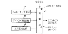
図1はDTC/DCCH識別回路の主な機能構成図である。この図1において、DTC/DCCH識別回路は、制御部1と、DCCHデータデコード部2と、DTC/DCCH判定部3と、誤判定検出部4とから構成されている。
【0047】
(制御部1): 制御部1は、1スロット受信毎に、先ずSYNC DCCHが、1、−1、0のいずれであるかを確認する。この確認で−1、即ちDTCであると確認されると、次にDCCHロケータの復号を行い、DTC識別結果を出力する。一方、上述のSYNC DCCHの確認で、−1でないと確認されると、DCCHデータ部のデコードを行うために、DCCHデータデコード部2に命令を与える。
【0048】
また、制御部1は、SCFのデコードを行う。即ち、CPE、R/N、BRIなどのデータのデコードを行って、SCFのデコードを行う。更に、SFPのデコードも行う。
【0049】
更にまた、制御部1は、SYNC DCCHが0であるか否かの確認も行う。この確認で0であると確認されると、DTC/DCCHの判定を行うようにDTC/DCCH判定部3に命令する。制御部1は、上述のSYNC DCCHが0であるか否かの確認で、0でないと判定されると、誤判定検出の命令を誤判定検出部4に与える。
【0050】
(DCCHデータデコード部2): DCCHデータデコード部2は、DCCHデータ部のデコードを行う。即ち、デインタリーブ、ビタビ復号、CRCチェック、再符号化などを行い、DCCHデータ部のデコードを行う。この処理の具体的な構成は後述する。
【0051】
DTC/DCCH判定部3は、先ずNFSPの値を更新することから始める。尚、FHALFは、0(フルレート)、又は1(ハーフレート)のいずれかの値をとる。NSFPは受信したSFPとは別にDSP自身で持つSFPの予測値であり、フルレートの場合は1づつ、ハーフレートの場合は2づつカウントアップする。次にDCCHのCRCがエラーしていたか否か、即ちCRC DCCH=0であるか否かを判断し、エラーしていない場合、即ち0の場合は、NDCCHを1カウントアップする。DCCHのCRCがエラーしている場合は、直ちに次の確認の、誤り数が閾値を超えているか否かを確認する。この確認で超えていない場合は、NDCCHを1カウントアップする。
【0052】
上記確認で誤り数が閾値を超えている場合は、SFPの復号結果に誤りがあるか否かを検出する。この確認で誤りがないと検出されると、NDCCHを1カウントアップする。次に受信したSFPと推定SFPとが一致するか否かを確認する。この確認で一致する場合は、NDCCHを1カウントアップする。
【0053】
また、上記受信したSFPと推定SFPとの一致の確認で、一致しない場合は、次に受信したSFPの値をNSFPに保存する。上記SFPの復号結果に誤りがあるか否かの検出で、誤りがある場合、又は上記NDCCHを1カウントアップする、又は受信したSFP(recvdSFP)の値をNSFPに保存するなどのいずれかの処理を終了すると、次にNDCCHが3以上か否かを確認する。この確認でNDCCHが3以上の場合はSYNC DCCH=1として、DCCH識別結果を出力する。
【0054】
しかしながら、上記NDCCHが3以上か否かの確認で、3以上でない場合は、DVCCの復号を行い、次にDCCHロケータの復号を行う。次にDVCCの復号の結果、誤りがあるか否かを確認する。この確認で誤りがない場合は、NDTCを1カウントアップする。
【0055】
上記DVCCの復号の結果に誤りがあるか否かの確認で、誤りがない場合、又はNDTCを1カウントアップした場合、次にDCCLの復号の結果を確認する。この確認で誤りなしと確認されると、次にNDTCを1カウントアップする。
【0056】
上記DCCLの復号の結果の確認で、誤り有り又は上記NDTCを1カウントアップすることを終了すると、次にNDTCが3以上であるか否かを確認する。この確認でNDTCが3以上である場合は、次にSYNC DCCH=−1とし、又はNDTCが3以上でない場合はDTCの識別結果を出力する。
【0057】
(誤判定検出部4): 誤判定検出部4は、先ずNFSPの値を更新する。具体的には、フルレートの場合は1づつカウントアップし、ハーフレートの場合は2づつカウントアップする。次に受信したSFPと推定SFPとが一致するか否かを確認する。この確認で受信したSFPと推定SFPとが一致する場合は、NOT SYNC=0として、誤判定検出処理を終了する。
【0058】
また、上述の受信したSFPと推定SFPとが一致するか否かの確認で、一致しない場合はNOT SYNCを1カウントアップする。次にNOT SYNCが閾値M2と一致するか否かを比較する。この比較でNOT SYNCが閾値M2と一致するときには、NDTC=0、NDCCH=0、SYNC DCCH=0、NOT SYNC=0として、誤判定検出処理を終了する。尚、上記NOTSYNCが閾値M2と一致するか否かの比較で、不一致と判定されると、そこで誤判定検出処理を終了する。
【0059】
(回路の全体動作フロー): 図5はDTC/DCCH識別回路の全体的な回路動作フローチャートである。この図5において、DTC/DCCH識別回路の処理は、1スロット受信毎(例えば、20msec程度)に一連の処理を行うものとする。また、図10に示すように、SYNC DCCHは、1のときにDCCHとし、−1のときにDTCとし、0のとき不明とする。先ず、1スロット毎の受信信号からSYNC DCCHが−1であるか否かを確認する(ステップS1)。この確認で−1、即ちDTCであると確認されると、次にDCCHロケータの復号だけを行って(ステップS2)、これで識別処理は終了することになる。
【0060】
一方、上述のSYNC DCCHの確認で(ステップS1)、−1でないと確認されると、次にDCCHデータ部のデコードを行う(ステップS3)。即ち、デインタリーブ、ビタビ復号、CRCチェック、再符号化などを行い、DCCHデータ部のデコードを行う。この処理の具体的な構成は後述する。次にSCFのデコードを行う(ステップS4)、即ち、CPE、R/N、BRIなどのデータのデコードを行って、SCFのデコードを行う。次にSFPのデコードを行う
(ステップS5)。
【0061】
次にSYNC DCCHが0であるか否かを確認する(ステップS6)。この確認で0であると確認されると、次にDTC/DCCHの判定を行い(ステップS7)、処理を終了する。このDTC/DCCHの判定方法については、更に詳しく後述する。一方、上述のSYNC DCCHが0であるか否かの確認で、0でないと判定されると、次に誤判定検出処理を行って(ステップS8)、処理を終了する。この処理の詳細は更に詳しく後述する。
【0062】
以上のような一連の処理を行うことで、DTC/DCCHの識別を能率的に、しかも迅速に行うことができるのである。そこで、更に、上述のDCCHデータ部のデコード(ステップS3)、DTC/DCCH判定(ステップS7)、誤判定検出(ステップS8)の詳細を説明する。
【0063】
(DCCHデータ部のデコード): 図6は上述の図5のDCCHデータ部のデコード処理の処理フローチャートである。この図6において、先ず、スロットに対するデインタリーブを行い(ステップS99)、次にレート(符号化率)1/2、拘束長6のビタビ復号を行う(ステップS100)。尚、畳み込み符号の復号法としては、ビタビ復号以外にも存在するが、ビタビ復号が最尤復号であることが知られている。また、ビタビ復号の方法としては、DSP内蔵のアクセラレータを使用する方法や、パスの絞り込みの方法を変えるなどを行うことも好ましい。
【0064】
次にCRCの演算を行い、受信したCRCと演算したCRCを比較する(ステップS101)。この比較で受信したCRCと演算したCRCとが一致した場合はCRCエラーなしとし、一致しない場合はCRCエラーありとする。次に復号結果を再びレート1/2、拘束長6で再符号化する(ステップS102)。ここで再符号化したビット列と受信したビット列とを比較し、異なる値をとるビット数の誤り数として(ステップS103)、DCCHデータ部のデコード処理を終了する。
【0065】
(DTC/DCCH判定): 図7は上述の図5のDTC/DCCHの判定の処理フローチャートである。この図7において、先ずNFSPの値を更新することから始める(ステップS10)。尚、FHALFは、0(フルレート)、又は1(ハーフレート)のいずれかの値をとる。NSFPは受信したSFPとは別にDSP自身で持つSFPの予測値であり、フルレートの場合は1づつ、ハーフレートの場合は2づつカウントアップする。尚、図11に示すようにデフォルトは、NDTC=0、NDCCH=0、SYNC DCCH=0、NSFP=0とする。
【0066】
次にDCCHのCRCがエラーしていたか否か、即ちCRC DCCH=0であるか否かを判断し(ステップS11)、エラーしていない場合、即ち0の場合は、NDCCHを1カウントアップ(NDCCH=NDCH+1)する(ステップS12)。DCCHのCRCがエラーしている場合は、直ちに次の確認の、誤り数が閾値を超えているか(REENC DCCH≦n)否かを確認する(ステップS13)。この確認で超えていない場合は、NDCCHを1カウントアップ(NDCCH=NDCCH+1)する(ステップS14)。
【0067】
上記確認で誤り数が閾値を超えている場合は、次にSFPの復号結果に誤りがあるか(ERSFP=0)否かを検出する(ステップS15)。この確認で誤りがない(ERSFP=0)と検出されると、NDCCHを1カウントアップする(ステップS16)。次に受信したSFP(recvdSFP)と推定SFP
(NSFP)とが一致するか否かを確認する(ステップS17)。この確認で一致する場合は、NDCCHを1カウントアップ(NDCCH=NDCH+1)する(ステップS18)。
【0068】
また、上記受信したSFPと推定SFPとの一致の確認で(ステップS17)、一致しない場合は、次に受信したSFP(recvdSFP)の値をNSFPに保存する(ステップS19)。
【0069】
上記SFPの復号結果に誤りがあるか否かの検出(ステップS15)で、誤りがある場合、上記NDCCHを1カウントアップする(ステップS18)、受信したSFP(recvdSFP)の値をNSFPに保存する(ステップS19)などのいずれかの処理を終了すると、次にNDCCHが3以上か否かを確認する(ステップS20)。この確認でNDCCHが3以上の場合はSYNC DCCH=1として(ステップS21)、DTC/DCCH判定の処理を終了する。
【0070】
しかしながら、上記NDCCHが3以上か否かの確認で(ステップS20)、3以上でない場合は、図8の一連の処理を行って、DTC/DCCH判定を終了する。即ち、DVCCの復号を行い(ステップS22)、次にDCCHロケータの復号を行う(ステップS23)。次にDVCCの復号の結果、誤りがあるか
(*(#ERDVCC)=0)否かを確認する(ステップS24)。この確認で誤りがない場合は、NDTCを1カウントアップ(*(#NDTC)=*(#NDTC)+1)する(ステップS25)。
【0071】
上記DVCCの復号の結果に誤りがあるか否かの確認で(ステップS24)、誤りがない場合、又はNDTCを1カウントアップした場合(ステップS25)、次にDCCLの復号の結果(*(#ERDCCL)=0)を確認する(ステップS26)。この確認で誤りなしと確認されると、次にNDTCを1カウントアップ(*(#NDTC)=*(#NDTC)+1)する(ステップS27)。
【0072】
上記DCCL(DCCHロケータ)の復号の結果の確認で(ステップS26)、誤り有り又は上記NDTCを1カウントアップする(ステップS27)ことを終了すると、次にNDTCが3以上であるか(*(#NDTC)≧3)否かを確認する(ステップS28)。この確認でNDTCが3以上である場合は、次にSYNC DCCH=−1とし(ステップS29)、又はNDTCが3以上でない場合はDTC/DCCHの判定の処理を終了する。
【0073】
(誤判定検出): 図9は上述の図5の誤判定検出の処理フローチャートである。この図9において、先ずNFSPの値を更新(NSFP=NSFP+1+FHALF)する(ステップS200)。具体的には、フルレートの場合は1づつカウントアップし、ハーフレートの場合は2づつカウントアップする。次に受信したSFP(recvdSFP)と推定SFP(NSFP)とが一致するか否かを確認する(ステップS201)。
【0074】
この確認で受信したSFPと推定SFPとが一致する場合は、NOT SYNC=0として(ステップS202)、誤判定検出処理を終了する。
【0075】
また、上述の受信したSFP(recvdSFP)と推定SFP(NSFP)とが一致するか否かの確認で(ステップS201)、一致しない場合はNOT SYNCを1カウントアップする(ステップS203)。次にNOT SYNCが閾値M2と一致するか否かを比較する(ステップS204)。この比較でNOT SYNCが閾値M2と一致するときには、NDTC=0、NDCCH=0、SYNC DCCH=0、、NOT SYNC=0として(ステップS205)、誤判定検出処理を終了する。尚、上記NOT SYNCが閾値M2と一致するか否かの比較で(ステップS204)、不一致と判定されると、そこで誤判定検出処理を終了する。
【0076】
(携帯装置の一例のハードウエア構成): 図4は上述の図1のDTC/DCCH識別回路の機能構成を実現するTDMAセルラシステム用の携帯装置の一例のハードウエア構成図である。図4において、携帯装置はアンテナ10と、高周波(RF)回路11と、アナログ/デジタル(A/D)変換回路12と、デジタルシグナルプロセス回路13と、CPU14とから構成されている。この図4においては、受信系の構成を中心として説明する。
【0077】
アンテナ10は基地局からのTDMAフレーム信号を捕捉し、捕捉した高周波信号は高周波回路11に与えられる。高周波回路11は高周波信号から周波数同調を行い、復調を行いベースバンドのTDMAフレーム信号を抽出し、アナログ/デジタル変換回路12に与える。アナログ/デジタル変換回路12は、ベースバンドのTDMAフレーム信号をデジタル信号に変換して、デジタル処理し易い信号形態に変換してデジタルシグナルプロセス回路13に与える。
【0078】
CPU14は、具体的にはマイクロプロセッサMPや、プログラムROM、ワーキングRAMなどから構成され、アナログ/デジタル変換回路12の変換を制御したり、デジタルシグナルプロセス回路13を制御して上述の『DCCHロケータの復号』、『SCFの復号』、『SFPの復号』、『DVCCの復号』、
『DCCHデータの復号』、『DTC/DCCH判定』などを行わせ、DTC/DCCHの識別結果を得る。
【0079】
デジタルシグナルプロセス回路13は、アナログ/デジタル変換回路12からのデジタル信号を、CPU14からの命令に従って処理して、上述の『DCCHロケータの復号』、『SCFの復号』、『SFPの復号』、『DVCCの復号』、『DCCHデータの復号』、『DTC/DCCH判定』などを行い、DTC/DCCHの識別結果をCPU14に与えるものである。
【0080】
(本発明の実施の形態の効果): 以上の実施の形態によれば、受信スロットがF−BCCHでなくても、即ち、受信したCRCと演算したCRCとが一致しなくても、DTC/DCCHの識別判定を行うことができる。また、ハミング符号の精度に依存せず、ビタビ復号結果を再符号化することによって、誤り数を推定しているため、最短では1スロット分の信号の受信だけでもDTC/DCCHの識別判定を高い精度で行うことができる。
【0081】
従って、非常に簡単な構成で、ハードウエア規模を大きくすることなく、能率的にしかも短時間に無線局装置からの受信信号がトラヒックチャネル/コントロールチャネルのいずれであるかを識別することができるトラヒックチャネル/コントロールチャネル識別回路及びその方法を実現することができる。
【0082】
(他の実施の形態): (1)尚、以上の実施の形態においては、主にDSP内でソフトウエア処理を行う場合の処理の構成を示しているが、他にハードウエア、例えば、ゲートアレイ回路或いはDSP内蔵のアクセラレータなどで実現することも好ましい。
【0083】
(2)また、異なる畳み込み符号化を施された複数の信号系列或いは、一方のみが畳み込み符号化された複数の信号系列を識別することにも適用可能である。
【0084】
(3)更に、上述の実施の形態のDTC/DCCH識別回路は、北米仕様のTDMAシステムだけでなく、日本のTDMA方式にデジタルセルラ方式(PDC)の基地局装置や、携帯電話装置にも若干のフォーマット調整(例えば、データビット数などの調整)を行うことで同じように適用することができる。
【0085】
【発明の効果】
以上述べた様に第1の発明は、無線局装置からの受信信号がトラヒックチャネル又はコントロールチャネルのいずれであるかを識別するトラヒックチャネル/コントロールチャネル識別回路において、受信信号からコントロールチャネルロケータ信号を検出して復号し、コントロールチャネルが存在する周波数帯を表すの符号情報を出力するコントロールチャネルロケータ復号手段と、受信信号からコントロールチャネルデータを復号するコントロールチャネルデータ復号手段と、受信信号から割り当てコントロールフィードバック信号を検出して復号する割り当てコントロールフィードバック復号手段と、受信信号からスーパフレームフェーズ信号を復号するスーパフレームフェーズ復号手段と、コントロールチャネルデータ復号手段と、割り当てコントロールフィードバック復号手段と、スーパフレームフェーズ復号手段との復号結果から、受信信号がトラヒックチャネル又はコントロールチャネルのいずれであるかを識別出力するトラヒックチャネル/コントロールチャネル識別手段とを備えたことで、非常に簡単な構成で、ハードウエア規模を大きくすることなく、能率的に無線局装置からの受信信号がトラヒックチャネル又はコントロールチャネルのいずれであるかを識別することができ、低消費電力化に寄与でき、LSI化にも適している。
【0086】
また、第2の発明は、無線局装置からの受信信号がトラヒックチャネル又はコントロールチャネルのいずれであるかを識別するトラヒックチャネル/コントロールチャネル識別方法において、トラヒックチャネル又はコントロールチャネルのいずれであるかの識別結果を保存して出力する保存処理と、上記識別結果の値を確認し、この識別結果の値がトラヒックチャネルに相当する第1の値である場合は、コントロールチャネルロケータ信号を検出して復号するコントロールチャネルロケータ信号復号処理と、上記識別結果の確認で、第1の値でない場合は、コントロールチャネルデータを復号するコントロールチャネルデータ復号処理と、割り当てコントロールフィードバック信号を検出して復号する割り当てコントロールフィードバック信号復号処理と、スーパフレームフェーズ信号を検出して復号するスーパフレームフェーズ信号復号処理と、上記保存手段の識別結果が不定又は不明に相当する第2の値であるか否かを確認する識別結果確認処理と、この確認で不定又は不明に相当する上記第2の値である場合は、次にトラヒックチャネル又はコントロールチャネルのいずれであるかの識別を行って、この識別結果を上記保存処理に保存させるトラヒックチャネル/コントロールチャネル識別処理とから構成することで、非常に簡単な構成で、短時間に無線局装置からの受信信号がトラヒックチャネル又はコントロールチャネルのいずれであるかを識別することができる。
【図面の簡単な説明】
【図1】本発明の実施の形態のデジタルトラヒックチャネル(DTC)/デジタルコントロールチャネル(DCCH)識別回路の主な機能構成図である。
【図2】DTCのダウンリンクのスロット構成と、DCCHのダウンリンクのスロット構成との説明図である。
【図3】F−BCCH、E−BCCH、S−BCCH、Reserved、SPACHなどに対するCRCの計算の説明図である。
【図4】本発明の実施の形態の携帯装置の一例のハードウエア構成図である。
【図5】本発明の実施の形態のDTC/DCCH識別回路の全体動作フローチャートである。
【図6】本発明の実施の形態のDCCHデータ部のデコード処理フローチャートである。
【図7】本発明の実施の形態のDTC/DCCH判定の処理フローチャート(その1)である。
【図8】本発明の実施の形態のDTC/DCCH判定の処理フローチャート(その2)である。
【図9】本発明の実施の形態の誤判定検出の処理フローチャートである。
【図10】本発明の実施の形態のSYNC DCCHの値の説明図である。
【図11】本発明の実施の形態のDTC/DCCH判定のデフォルトの説明図である。
【符号の説明】
1…制御部、2…DCCHデータデコード部、3…DTC/DCCH判定部、4…誤判定検出部、10…アンテナ、11…高周波(RF)回路、12…アナログ/デジタル(A/D)変換回路、13…デジタルシグナルプロセス回路、14…CPU、S3…DCCHデータ部デコード処理、S7…DTC/DCCH判定処理、S8…誤判定検出処理。[0001]
TECHNICAL FIELD OF THE INVENTION
The present invention relates to a traffic channel / control channel identification circuit and a traffic channel / control channel identification method, and can be applied to, for example, a mobile station device in a North American TDMA cellular system.
[0002]
[Prior art]
In recent years, TDMA cellular systems have been used. For example, in North America TIA
(Telecommunications Industry Association) recommends the TDMA digital cellular system as IS-54B.
[0003]
The North American TDMA cellular system uses an analog modulation method (for example, FM), so-called Advanced Mobile Phone System (AMPS), or a digital modulation method for each channel (bandwidth of 30 kHz / 1 channel).
(Π / 4 shift QPSK). In each modulation method, a control channel (Analog Control Channel: ACC) for location registration, reception waiting, and transmission request to the base station, a “Digital Control Channel”: DCCH, and traffic (communication) for exchanging user information ) Channel (analog voice channel: AVC), “digital traffic channel” (DTC), and the like.
[0004]
That is, in the dual mode system, one of ACC, AVC, DCCH, and DTC is assigned to a certain channel.
[0005]
When talking on a mobile terminal, ACC or DCCH must first be received, regardless of whether the call is received or transmitted. AVC or DTC can be received only when the channel number (and the slot number in the case of DTC) is indicated on the control channel. Here, a problem arises as to how to find the control channel.
[0006]
In the case of ACC, since a resident channel is determined, the channel may be received. However, in the case of DCCH, the resident channel is not particularly determined. However, since it is practically meaningless to search for all channels having more than 1000 channels, a frequency area in which there is a high possibility that the DCCH exists is determined.
This is because it is efficient if DCCHs are searched in order from the area in which the DCCH is likely to exist from some divided frequency areas. However, even in this case, it is necessary to identify whether the reception channel is the DCCH. In particular, a method of identifying whether the reception channel is DTC or DCCH is important for shortening the time until receiving DCCH.
[0007]
Therefore, FIG. 2 is a diagram showing the slot configuration of the downlink of the DTC and DCCH (from the base station BS to the mobile station MS). As shown in FIG. 2, the DTC slot and the DCCH slot have the same total number of bits and the same sync pattern, but also have differently encoded signals including the data portion. In FIG. 2, the SACCH is a Slow Associated Control Channel. CDVCC is a Coded Digital Verification Color Code (encoded digital confirmation color code). CDL is a coded DCCH Locator. SCF is a shared control feedback (assigned control feedback signal), and represents a random access control signal. CSFP is Coded SuperFrame Phase, which is phase information indicating a position in a superframe.
[0008]
Here, when determining whether a certain channel is a DCCH or not, assuming that the received signal level is at a receivable level, the mobile station first searches for a sync pattern. If there is no sync pattern, it means that the channel is likely to be AMPS. Therefore, the process moves to another channel and the sync pattern check is started again.
[0009]
If a sync pattern is found, it must identify whether the channel is DTC or DCCH. As the identification method, the following three or some combinations are conceivable.
[0010]
(1) Identify whether the DATA part is of DTC or DCCH. (2) Determine whether it is CDVCC or CSFP.
(3) Determine whether SACCH / CDL or SCF.
[0011]
The method of (1) utilizes the coincidence / mismatch of CRCs due to the difference in encoding between DTC data and DCCH data. The difference between the CRC calculation method of DTC / DCCH and convolutional coding is as follows.
[0012]
In DTC data, CRC is from
[0013]
In DCCH data, DVCC = 0 is set for FBCCH (Fast Broadcast Channel), and 16 bits are calculated and then inverted. The rate is 1/2, the convolution code has a constraint length of 6, and there is no slot interleaving. Further, 16 bits are calculated using DVCC for SPACH (Smsch, Pch and Arch Channel) by collectively including SMSM (Short Message Service Channel) / PCH (Paging Channel) / ARCH (Access Response Channel). It is assumed that the rate is 1/2, the convolutional code has a constraint length of 6, and there is no slot interleaving.
[0014]
For slots other than FBCCH and SPACH, DVCC is used, 16 bits are calculated and then inverted. The rate is 1/2, the convolution code has a constraint length of 6, and there is no slot interleaving.
[0015]
As described above, since the method of calculating the CRC is different, such as the generator polynomial, the total number of bits, whether to use DVCC, etc., if the CRC can be calculated from the result of decoding the received data, it is possible to identify which type was transmitted. .
[0016]
Next, regarding the above method (2), first, the encoding method has the following differences. For CDVCC, the same 8-bit value (except 00hex) is transmitted every slot. Hamming coding is performed on 8 bits, and a 4-bit redundancy coefficient is calculated. The CSFP is incremented by one for each slot from 0 hex (hex means a hexadecimal number) to 1 Fhex. Hamming coding is performed on 8 bits, and the calculated 4 bits are inverted and used.
[0017]
Next, the method (3) will be described. However, using the SACCH for identification is disadvantageous in terms of the time required for identification. For CDL, the same 7-bit value is transmitted every slot. Hamming coding is performed on 8 bits (MSB0 is added), and the calculated 4 bits are inverted and used. As for SCF, CPE (11 bits), R / N (5 bits), and BRI (6 bits) are interleaved. The CPE is transmitted with a 7-bit value. Four bits calculated by Hamming encoding 8 bits (MSB0 is added) are inverted and used.
[0018]
[Problems to be solved by the invention]
However, in the above method (1), the received signal is decoded according to the DCCH decoding method, but the CRC cannot always be calculated. That is, the CRC calculation method changes according to the phase of the SFP (Super Frame Phase). The CRC operation law can be represented as shown in FIG.
[0019]
In FIG. 3, the numbers of F-BCCH, E-BCCH, S-BCCH, and SPACH differ for each DCCH channel. In addition, F-BCCH is an abbreviation of Fast-BroadCast Channel, E-BCCH is an abbreviation of Extended-BCCH, S-BCCH is an abbreviation of Short message service-BCCH, Reserved is an abbreviation of Reserved slot, and SPACHSchmach is an abbreviation of Reserved slot. It is an abbreviation for CHChannel. For details of these functions, see the literature: “Oki Electric Research and Development”, June 1995, No. 167, Vol. 62, No. 3 in the article entitled "Software for US TDMA Cellular Portable Devices" on pages 79-82.
[0020]
The number of F-BCCHs, E-BCCHs, S-BCCHs, and SPACHs and the DVCC value can be determined only by receiving the F-BCCH and analyzing the signal content.
[0021]
Therefore, when DCCH decoding is performed by the above-described method (1), there is a problem that the CRC matches only with the F-BCCH immediately after the DCCH synchronization. Also, when performing DTC decoding, two slots must be waited in consideration of slot interleaving, and a memory for storing a received signal is required, which causes a problem of an increase in memory capacity.
[0022]
In the above method (2), whether the DTC or DCCH is determined depending on whether decoding by the Hamming code can be performed. However, since the presence or absence of an error of 3 bits or more cannot be detected for the Hamming code, a more accurate determination is required. However, there is a problem that it is desired to make a determination after receiving several slots, and it takes a long time to make the determination. The above method (3) has the same problem as the above (2).
[0023]
From the above, it is possible to identify whether a signal received from a radio station is a traffic channel or a control channel efficiently and in a short time with a very simple configuration and without increasing the hardware scale. Therefore, there is a need for a traffic channel / control channel identification circuit and a method thereof.
[0024]
[Means for Solving the Problems]
Therefore, the invention of
[0025]
That is, according to the first aspect of the present invention, a control channel locator decoding means for detecting and decoding a control channel locator signal (for example, a DCCH locator) from the received signal and outputting code information indicating a frequency band in which the control channel exists. "Control channel data decoding means" for decoding control channel data (for example, DCCH data) from the received signal, and "allocation control for detecting and decoding an allocation control feedback signal (for example, SCF) from the received signal. Feedback decoding means ";" superframe phase decoding means "for decoding a superframe phase signal (for example, SFP) from the received signal;" control channel data decoding means "; And a "traffic channel / control channel discriminating means" for discriminating and outputting whether the received signal is a traffic channel or a control channel from the decoding result of the super frame phase decoding means. It is.
[0026]
Since the control channel locator signal is a signal of code information indicating the frequency band in which the control channel exists, the frequency band in which the control channel exists can be known by detecting and decoding this locator signal.
[0027]
By adopting such a configuration, traffic channel / control channel discrimination can be efficiently performed based on the results of several decoding means, and the circuit configuration is easy, so that the configuration is also suitable for miniaturization. Further, even if the CRC of the received signal does not match the calculated CRC, it is possible to identify the received signal in a short time with high accuracy.
[0028]
Further, the invention according to
[0029]
By adopting such a configuration, it is possible to easily perform error determination detection for identification with a simple circuit configuration.
[0030]
According to a third aspect of the present invention, there is provided a traffic channel / control channel identification method for identifying whether a signal received from a wireless station device is a traffic channel or a control channel. It is the solution.
[0031]
That is, according to the third aspect of the present invention, there is provided a "storing process" for storing and outputting an identification result indicating whether the channel is a traffic channel or a control channel, and confirming the value of the identification result. If the value is the first value corresponding to the channel, the control channel locator signal (for example, DCCH locator) is detected and decoded. If the value is not a value, a "control channel data decoding process" for decoding control channel data, an "assignment control feedback signal decoding process" for detecting and decoding an assignment control feedback signal (for example, SCF), and a superframe phase signal ( For example, SFP is detected and decrypted. "Pass frame phase signal decoding processing" and "identification result confirmation processing" for confirming whether or not the identification result of the storage processing is a second value corresponding to indefinite or unknown. If it is the second value to be processed, it is then determined whether the channel is a traffic channel or a control channel, and the result of this identification is stored in the above-mentioned storage process. Is what you do.
[0032]
By adopting such a configuration, it is possible to perform the traffic channel / control channel identification and the error determination detection very efficiently, and it is possible to realize the configuration with a simple configuration.
[0033]
Furthermore, in the invention of
[0034]
By decoding control channel data with such a configuration, data with few errors can be obtained.
[0035]
Further, according to the invention of claim 5, the "traffic channel / control channel identification processing" according to
[0036]
By performing identification using such a configuration, it is possible to efficiently identify a traffic channel / control channel from a short received signal even if CRCs do not match.
[0037]
Still further, according to a sixth aspect of the present invention, in the configuration of any of the third to fifth aspects, it is determined whether or not the identification result of the “identification result confirmation processing” is a second value corresponding to indefinite or unknown. If the second value is not the second value, it is further confirmed whether or not the predicted value for the superframe phase matches the decoding result. If not, the erroneous determination detection process for detecting the erroneous determination is performed. Is what you do.
[0038]
By adopting such a configuration, after determining the current channel as a control channel (for example, DCCH), it is possible to easily detect an error determination for a control channel or a traffic channel from an SFP predicted value and a decoding result with a simple configuration. Can be.
[0039]
According to a seventh aspect of the present invention, the “erroneous determination detection processing” of the sixth aspect is configured such that each time the superframe phase signal (for example, SFP) is detected, whether or not the predicted value and the decoding result match. Is checked, and if they do not match, counting is performed by the third counter, and when the count value of the third counter reaches the sixth value, an erroneous determination is made.
[0040]
With such a configuration, error determination can be performed quickly and with a simple configuration.
[0041]
BEST MODE FOR CARRYING OUT THE INVENTION
Next, a preferred embodiment of the present invention will be described with reference to the drawings.
Therefore, the DTC / DCCH identification circuit according to the present embodiment uses “DCCH locator decoding” to determine which of two types of signal sequences (DTC / DCCH) assigned to the same region by different encoding. Means, SCF decoding means, SFP decoding means, DVCC decoding means, DCCH data decoding means, DTC / DCCH judgment means, and erroneous judgment detection Means ”.
[0042]
The “SCF decoding means” includes a deinterleaving means and a CPE decoding means. The “DCCH decoding means” includes deinterleaving means, Viterbi decoding means, CRC calculation / comparison means, re-encoding means, comparison means for comparing a received sequence with a re-encoded sequence, Storage means.
[0043]
The "DTC / DCCH determination means" includes means for incrementing the predicted value of the SFP, means for incrementing the counter NDCCH by 1 when there is no CRC error in the DCCH decoding result, and the number of errors being equal to or less than the first set value n. Means for incrementing the NDCCH by 1; means for incrementing the NDCCH by 1 if there is no error in the decoding result of the SFP; and means for incrementing the NDCCH by 1 if the predicted value of the SFP matches the decoding result. Is provided.
[0044]
Further, in this embodiment, in addition to the above-described configuration, means for incrementing the counter NDTC by one when the decoding result of DVCC has no error, and means for incrementing the counter NDTC by one when the decoding result of DCCL has no error When the NDCCH has reached the second set value, it is determined to be DCCH (determination flag SYNC DCCH = 1), and when the NDTC has reached the second set value, it is determined to be DTC ( Means for making a determination flag SYNC DCCH = -1) is provided.
[0045]
Further, the "erroneous determination detecting means" includes means for incrementing the predicted value of the SFP after determining the current channel as DCCH, means for comparing the predicted value of the SFP with the decoding result, If not, the counter NOT SYNC = 0 is set. If the predicted value of the SFP and the decoding result do not match, the counter NOTSYNC is incremented by 1. If the counter NOT SYNC reaches the fourth threshold, NDTC = Means for setting NDCCH = NOT SYNC = 0 and setting the determination flag SYNC DCCH to 0, thereby realizing a DTC / DCCH identification circuit.
[0046]
Next, a detailed configuration and operation for realizing the above configuration will be described.
FIG. 1 is a main functional configuration diagram of the DTC / DCCH identification circuit. In FIG. 1, the DTC / DCCH identification circuit includes a
[0047]
(Control unit 1): The
[0048]
Further, the
[0049]
Furthermore, the
[0050]
(DCCH data decoding unit 2): The DCCH
[0051]
The DTC /
[0052]
If the number of errors exceeds the threshold in the above check, it is detected whether or not there is an error in the SFP decoding result. If no error is detected in this check, the NDCCH is counted up by one. Next, it is confirmed whether or not the received SFP matches the estimated SFP. If they match, the NDCCH is counted up by one.
[0053]
If it is determined that the received SFP matches the estimated SFP and the two do not match, the value of the next received SFP is stored in the NSFP. Detection of whether or not there is an error in the decoding result of the SFP, if there is an error, or any one of processing such as counting up the NDCCH by one, or storing the value of the received SFP (recvdSFP) in the NSFP Is completed, it is checked whether the number of NDCCH is 3 or more. If the number of NDCCHs is three or more, SYNC DCCH = 1 is set and the DCCH identification result is output.
[0054]
However, if it is determined whether or not the NDCCH is 3 or more, if it is not 3 or more, DVCC is decoded, and then the DCCH locator is decoded. Next, it is confirmed whether or not there is an error as a result of DVCC decoding. If there is no error in this check, NDTC is counted up by one.
[0055]
When it is determined whether there is an error in the DVCC decoding result, if there is no error, or if NDTC is counted up by 1, the DCCL decoding result is checked next. If it is confirmed that there is no error, the NDTC is incremented by one.
[0056]
After confirming the result of DCCL decoding, if there is an error or the NDTC is counted up by one, then it is confirmed whether or not NDTC is 3 or more. If NDTC is 3 or more in this confirmation, then SYNC DCCH = −1, or if NDTC is not 3 or more, the DTC identification result is output.
[0057]
(Error determination detection unit 4): The error
[0058]
In the above-described confirmation of whether the received SFP matches the estimated SFP, if they do not match, the NOT SYNC is counted up by one. Next, it is determined whether NOT SYNC matches the threshold value M2. When NOT SYNC matches the threshold value M2 in this comparison, NDTC = 0, NDCCH = 0, SYNC DCCH = 0, NOT SYNC = 0, and the erroneous determination detection process ends. If it is determined that the NOTSYNC is equal to the threshold value M2, it is determined that they do not match, the erroneous determination detection process ends.
[0059]
(Overall Operation Flow of Circuit): FIG. 5 is an overall circuit operation flowchart of the DTC / DCCH identification circuit. In FIG. 5, it is assumed that the DTC / DCCH identification circuit performs a series of processes each time one slot is received (eg, about 20 msec). Also, as shown in FIG. 10, the SYNC DCCH is set to DCCH when it is 1, DTC when it is -1, and unknown when it is 0. First, it is checked whether or not the SYNC DCCH is -1 from the received signal for each slot (step S1). If it is confirmed by this confirmation that it is -1, that is, DTC, then only the decoding of the DCCH locator is performed (step S2), and the identification processing ends.
[0060]
On the other hand, if the above-mentioned SYNC DCCH is confirmed (step S1) and it is confirmed that it is not -1, the DCCH data part is decoded next (step S3). That is, it performs deinterleaving, Viterbi decoding, CRC check, re-encoding, etc., and decodes the DCCH data part. The specific configuration of this processing will be described later. Next, the SCF is decoded (step S4), that is, the data such as CPE, R / N, and BRI is decoded, and the SCF is decoded. Next, the SFP is decoded.
(Step S5).
[0061]
Next, it is confirmed whether or not the SYNC DCCH is 0 (step S6). If it is confirmed that the value is 0, the DTC / DCCH is determined next (step S7), and the process ends. The DTC / DCCH determination method will be described later in more detail. On the other hand, if it is determined that the SYNC DCCH is not 0 when it is not 0, then an erroneous determination detection process is performed (step S8), and the process ends. The details of this process will be described later in more detail.
[0062]
By performing a series of processes as described above, DTC / DCCH can be efficiently and quickly identified. Therefore, the details of the above-described decoding of the DCCH data portion (step S3), DTC / DCCH determination (step S7), and erroneous determination detection (step S8) will be described.
[0063]
(Decoding of DCCH Data Part): FIG. 6 is a processing flowchart of the above-described decoding processing of the DCCH data part of FIG. In FIG. 6, first, deinterleaving is performed on the slot (step S99), and then Viterbi decoding with a rate (coding rate) of 1/2 and a constraint length of 6 is performed (step S100). It should be noted that there are other methods of decoding convolutional codes than Viterbi decoding, but it is known that Viterbi decoding is maximum likelihood decoding. As a method of Viterbi decoding, it is also preferable to use a method using an accelerator with a built-in DSP or change a method of narrowing down paths.
[0064]
Next, CRC calculation is performed, and the received CRC and the calculated CRC are compared (step S101). If the received CRC and the calculated CRC match in this comparison, it is determined that there is no CRC error, and if they do not match, it is determined that there is a CRC error. Next, the decoding result is re-encoded again at a rate of 1/2 and a constraint length of 6 (step S102). Here, the re-encoded bit sequence is compared with the received bit sequence, the number of bits having a different value is determined as the number of errors (step S103), and the decoding process of the DCCH data section ends.
[0065]
(DTC / DCCH Determination): FIG. 7 is a processing flowchart of the above-described DTC / DCCH determination in FIG. In FIG. 7, the process starts by updating the value of NFSP (step S10). Note that FHALF takes a value of either 0 (full rate) or 1 (half rate). NSFP is the predicted value of the SFP that the DSP itself has separately from the received SFP, and it is incremented by 1 for full rate and 2 for half rate. Note that, as shown in FIG. 11, the defaults are NDTC = 0, NDCCH = 0, SYNC DCCH = 0, and NSFP = 0.
[0066]
Next, it is determined whether or not the CRC of the DCCH has an error, that is, whether or not CRC DCCH = 0 (step S11). If there is no error, that is, if it is 0, the NDCCH is counted up by one (NDCCH). = NDCH + 1) (step S12). If the CRC of the DCCH is erroneous, it is immediately confirmed whether the number of errors in the next confirmation exceeds the threshold (REENC DCCH ≦ n) (step S13). If the number does not exceed this check, the NDCCH is counted up by one (NDCCH = NDCCH + 1) (step S14).
[0067]
If the number of errors exceeds the threshold in the above check, it is next detected whether or not there is an error in the SFP decoding result (ERSFP = 0) (step S15). If it is detected that there is no error (ERSFP = 0), the NDCCH is counted up by 1 (step S16). Next received SFP (recvdSFP) and estimated SFP
(NSFP) is confirmed (step S17). If they match, the NDCCH is counted up by one (NDCCH = NDCH + 1) (step S18).
[0068]
If the received SFP matches the estimated SFP (step S17), if not, the next received SFP (recvdSFP) value is stored in the NSFP (step S19).
[0069]
If there is an error in the decoding result of the SFP (step S15), and if there is an error, the NDCCH is counted up by one (step S18), and the received SFP (recvdSFP) value is stored in the NSFP. When any of the processes such as (Step S19) is completed, it is next checked whether or not NDCCH is 3 or more (Step S20). If the number of NDCCHs is 3 or more, SYNC DCCH = 1 is set (step S21), and the DTC / DCCH determination process ends.
[0070]
However, it is determined whether or not the NDCCH is 3 or more (step S20). If the NDCCH is not 3 or more, a series of processing in FIG. 8 is performed, and the DTC / DCCH determination ends. That is, DVCC decoding is performed (step S22), and then DCCH locator decoding is performed (step S23). Next, if there is an error as a result of DVCC decoding
(* (# ERDVCC) = 0) is checked (step S24). If there is no error in this check, the NDTC is counted up by one (* (# NDTC) = * (# NDTC) +1) (step S25).
[0071]
When it is confirmed whether there is an error in the DVCC decoding result (step S24), if there is no error, or if NDTC is counted up by 1 (step S25), then the DCCL decoding result (* (# (ERDCCL) = 0) is confirmed (step S26). If it is confirmed that there is no error, the NDTC is incremented by one (* (# NDTC) = * (# NDTC) +1) (step S27).
[0072]
When the result of decoding of the DCCL (DCCH locator) is confirmed (step S26), if there is an error or the NDTC is counted up by one (step S27), then the NDTC is 3 or more (* (#) (NDTC) ≧ 3) It is confirmed whether or not (step S28). If NDTC is 3 or more in this check, then SYNC DCCH is set to −1 (step S29), or if NDTC is not 3 or more, the process of DTC / DCCH determination ends.
[0073]
(Error determination detection): FIG. 9 is a processing flowchart of the error determination detection of FIG. 5 described above. In FIG. 9, first, the value of the NFSP is updated (NSFP = NSFP + 1 + FHALF) (step S200). Specifically, in the case of the full rate, the count is incremented by one, and in the case of the half rate, the count is incremented by two. Next, it is confirmed whether or not the received SFP (recvdSFP) matches the estimated SFP (NSFP) (step S201).
[0074]
If the SFP received in this check matches the estimated SFP, NOT SYNC = 0 is set (step S202), and the erroneous determination detection processing ends.
[0075]
In addition, it is determined whether or not the received SFP (recvdSFP) matches the estimated SFP (NSFP) (step S201). If they do not match, the NOT SYNC is counted up by one (step S203). Next, it is determined whether NOT SYNC matches the threshold value M2 (step S204). If NOT SYNC matches the threshold M2 in this comparison, NDTC = 0, NDCCH = 0, SYNC DCCH = 0, NOT SYNC = 0 (step S205), and the erroneous determination detection process ends. If it is determined that the NOT SYNC is equal to the threshold value M2 (step S204), then the erroneous determination detection process is terminated.
[0076]
(Hardware Configuration of One Example of Portable Device) FIG. 4 is a hardware configuration diagram of one example of a portable device for a TDMA cellular system that realizes the functional configuration of the DTC / DCCH identification circuit of FIG. In FIG. 4, the portable device includes an
[0077]
The
[0078]
The
"Decoding of DCCH data", "DTC / DCCH determination", and the like are performed to obtain a DTC / DCCH identification result.
[0079]
The digital
[0080]
(Effect of Embodiment of the Present Invention) According to the above embodiment, even if the reception slot is not the F-BCCH, that is, even if the received CRC does not match the calculated CRC, the DTC / DCCH identification can be determined. In addition, since the number of errors is estimated by re-encoding the Viterbi decoding result without depending on the accuracy of the Hamming code, the DTC / DCCH identification determination is high even in the shortest reception of a signal for only one slot. Can be done with precision.
[0081]
Therefore, the traffic can be distinguished efficiently and in a short period of time from a radio station device as a traffic channel or a control channel, with a very simple configuration and without increasing the hardware scale. A channel / control channel identification circuit and method can be realized.
[0082]
(Other Embodiments): (1) In the above embodiment, the processing configuration when software processing is mainly performed in the DSP is shown. However, other hardware, for example, gates It is also preferable to realize this using an array circuit or an accelerator with a built-in DSP.
[0083]
(2) The present invention is also applicable to identifying a plurality of signal sequences subjected to different convolutional coding or a plurality of signal sequences only one of which is convolutionally coded.
[0084]
(3) Further, the DTC / DCCH identification circuit according to the above-described embodiment is slightly applied not only to the TDMA system of the North American specification but also to the base station device of the digital cellular system (PDC) and the mobile phone device in the Japanese TDMA system. By applying a format adjustment (for example, adjusting the number of data bits, etc.), the same can be applied.
[0085]
【The invention's effect】
As described above, the first invention detects a control channel locator signal from a received signal in a traffic channel / control channel identification circuit that identifies whether the received signal from the wireless station device is a traffic channel or a control channel. Control channel locator decoding means for decoding code and outputting code information indicating a frequency band in which a control channel exists, control channel data decoding means for decoding control channel data from a received signal, and assignment control feedback signal from the received signal Allocation control feedback decoding means for detecting and decoding, super frame phase decoding means for decoding a super frame phase signal from the received signal, control channel data decoding means, Allocation control feedback decoding means, and a traffic channel / control channel identification means for identifying and outputting whether the received signal is a traffic channel or a control channel from decoding results of the superframe phase decoding means, With a very simple configuration, it is possible to efficiently identify whether the received signal from the wireless station device is a traffic channel or a control channel without increasing the hardware scale, contributing to lower power consumption. It is suitable for LSI.
[0086]
According to a second invention, in a traffic channel / control channel identification method for identifying whether a signal received from a wireless station device is a traffic channel or a control channel, identification of whether the signal is a traffic channel or a control channel is provided. A storage process for storing and outputting the result and a value of the identification result are confirmed. If the value of the identification result is the first value corresponding to the traffic channel, the control channel locator signal is detected and decoded. In the control channel locator signal decoding process and the confirmation of the identification result, if it is not the first value, the control channel data decoding process for decoding the control channel data, and the assignment control feedback for detecting and decoding the assignment control feedback signal Signal decoding processing, a superframe phase signal decoding processing for detecting and decoding a superframe phase signal, and an identification result for confirming whether or not the identification result of the storage means is a second value corresponding to indefinite or unknown. If the second value corresponds to indefinite or unknown in the confirmation processing and this confirmation, then it is determined whether it is a traffic channel or a control channel, and this identification result is stored in the storage processing. With the configuration including the traffic channel / control channel identification processing to be performed, it is possible to identify whether the signal received from the wireless station device is a traffic channel or a control channel in a short time with a very simple configuration.
[Brief description of the drawings]
FIG. 1 is a main functional configuration diagram of a digital traffic channel (DTC) / digital control channel (DCCH) identification circuit according to an embodiment of the present invention.
FIG. 2 is an explanatory diagram of a downlink slot configuration of DTC and a downlink slot configuration of DCCH.
FIG. 3 is an explanatory diagram of calculation of CRC for F-BCCH, E-BCCH, S-BCCH, Reserved, SPACH, and the like.
FIG. 4 is a hardware configuration diagram of an example of a portable device according to the embodiment of the present invention.
FIG. 5 is an overall operation flowchart of the DTC / DCCH identification circuit according to the embodiment of the present invention.
FIG. 6 is a flowchart of a decoding process of a DCCH data section according to the embodiment of the present invention.
FIG. 7 is a flowchart (part 1) of a DTC / DCCH determination process according to the embodiment of the present invention.
FIG. 8 is a flowchart (part 2) of a DTC / DCCH determination process according to the embodiment of the present invention.
FIG. 9 is a processing flowchart of erroneous determination detection according to the embodiment of the present invention.
FIG. 10 is an explanatory diagram of SYNC DCCH values according to an embodiment of the present invention.
FIG. 11 is a diagram illustrating a default of DTC / DCCH determination according to the embodiment of this invention.
[Explanation of symbols]
DESCRIPTION OF
Claims (7)
上記受信信号からコントロールチャネルロケータ信号を検出して復号し、コントロールチャネルが存在する周波数帯を表す符号情報を出力するコントロールチャネルロケータ復号手段と、
上記受信信号からコントロールチャネルデータを復号するコントロールチャネルデータ復号手段と、
上記受信信号から割り当てコントロールフィードバック信号を検出して復号する割り当てコントロールフィードバック復号手段と、
上記受信信号からスーパフレームフェーズ信号を復号するスーパフレームフェーズ復号手段と、
上記コントロールチャネルデータ復号手段と、上記割り当てコントロールフィードバック復号手段と、上記スーパフレームフェーズ復号手段との復号結果から、上記受信信号がトラヒックチャネル又はコントロールチャネルのいずれであるかを識別出力するトラヒックチャネル/コントロールチャネル識別手段と
を備えたことを特徴とするトラヒックチャネル/コントロールチャネル識別回路。In a traffic channel / control channel identification circuit for identifying whether a signal received from a wireless station device is a traffic channel or a control channel,
Control channel locator decoding means for detecting and decoding the control channel locator signal from the received signal, and outputting code information indicating a frequency band in which the control channel exists,
Control channel data decoding means for decoding control channel data from the received signal,
Assignment control feedback decoding means for detecting and decoding the assignment control feedback signal from the received signal,
Superframe phase decoding means for decoding a superframe phase signal from the received signal;
A traffic channel / control for discriminating and outputting whether the received signal is a traffic channel or a control channel based on decoding results of the control channel data decoding means, the assignment control feedback decoding means, and the superframe phase decoding means. A traffic channel / control channel identification circuit, comprising: channel identification means.
トラヒックチャネル又はコントロールチャネルのいずれであるかの識別結果を保存して出力する保存処理と、
上記識別結果の値を確認し、この識別結果の値がトラヒックチャネルに相当する第1の値である場合は、コントロールチャネルロケータ信号を検出して復号するコントロールチャネルロケータ信号復号処理と、
上記識別結果の確認で、上記第1の値でない場合は、コントロールチャネルデータを復号するコントロールチャネルデータ復号処理と、
割り当てコントロールフィードバック信号を検出して復号する割り当てコントロールフィードバック信号復号処理と、
スーパフレームフェーズ信号を検出して復号するスーパフレームフェーズ信号復号処理と、
上記保存処理の識別結果が不定又は不明に相当する第2の値であるか否かを確認する識別結果確認処理と、
この確認で不定又は不明に相当する上記第2の値である場合は、トラヒックチャネル又はコントロールチャネルのいずれであるかの識別を行って、この識別結果を上記保存処理によって保存させるトラヒックチャネル/コントロールチャネル識別処理とから構成する
ことを特徴とするトラヒックチャネル/コントロールチャネル識別方法。In a traffic channel / control channel identification method for identifying whether a signal received from a wireless station device is a traffic channel or a control channel,
A storage process for storing and outputting the identification result of whether the traffic channel or the control channel,
Checking the value of the identification result, and if the value of the identification result is the first value corresponding to the traffic channel, detecting a control channel locator signal and decoding the control channel locator signal;
If the identification result is not the first value, control channel data decoding processing for decoding control channel data;
An assignment control feedback signal decoding process for detecting and decoding the assignment control feedback signal,
A superframe phase signal decoding process for detecting and decoding a superframe phase signal;
Identification result confirmation processing for confirming whether or not the identification result of the storage processing is a second value corresponding to indefinite or unknown;
If the second value corresponds to indefinite or unknown in this confirmation, whether the channel is a traffic channel or a control channel is identified, and the identification result is stored in the traffic channel / control channel stored in the storage process. A traffic channel / control channel identification method characterized by comprising an identification process.
ことを特徴とする請求項3記載のトラヒックチャネル/コントロールチャネル識別方法。The control channel data decoding process performs deinterleaving on the received signal, performs maximum likelihood decoding on the deinterleaved signal, performs an error check on the maximum likelihood decoding result, and performs 4. The configuration according to claim 3, wherein re-encoding is performed, a bit sequence obtained by the re-encoding is compared with a received signal bit sequence, and the number of bits having different values is set as the number of errors. Traffic channel / control channel identification method.
上記受信信号から確認カラーコード信号を検出して復号し、この復号結果に誤りがない場合は第2のカウンタをカウントアップし、上記コントロールチャネルロケータ信号に対する復号結果に誤りがない場合に上記第2のカウンタをカウントアップし、上記第2のカウンタが第5の値に達している場合に、上記トラヒックチャネルとして識別出力するトラヒックチャネル識別処理とから構成する
ことを特徴とする請求項3又は4記載のトラヒックチャネル/コントロールチャネル識別方法。The traffic channel / control channel identification processing counts up a first counter when there is no error in the error check on the decoding result for the control channel data, and the number of errors obtained by the error check is equal to or less than a third value. In this case, the first counter is counted up, and if there is no error in the decoding result for the superframe phase signal, the first counter is counted up, and the predicted value for the superframe phase signal matches the decoding result. Also in the case of performing the control channel identification process, the first counter is counted up, and when the count number of the first counter has reached a fourth value, the control channel is identified and output as the control channel.
A confirmation color code signal is detected and decoded from the received signal. If there is no error in the decoding result, the second counter is counted up. If there is no error in the decoding result for the control channel locator signal, the second counter is counted. 5. A traffic channel identifying process which counts up a counter of the second channel and, when the second counter has reached a fifth value, identifies and outputs the traffic channel as the traffic channel. Traffic channel / control channel identification method.
こと特徴とする請求項3〜5のいずれかに記載のトラヒックチャネル/コントロールチャネル識別方法。Further, in checking whether or not the identification result of the identification result confirmation processing is the second value corresponding to indefinite or unknown, if the identification value is not the second value, the prediction value and the decoding result for the superframe phase The traffic channel / control channel identification according to any one of claims 3 to 5, wherein it is configured to check whether or not the traffic channel matches, and to perform erroneous judgment detection processing for detecting erroneous judgment when they do not match. Method.
ことを特徴とする請求項6の記載のトラヒックチャネル/コントロールチャネル識別方法。In the erroneous determination detection processing, it is checked whether or not the predicted value and the decoding result of the super frame phase signal match each time detection is performed, and if they do not match, the count is counted by a third counter. 7. The traffic channel / control channel identification method according to claim 6, wherein an erroneous determination is made when the count value of the counter reaches a sixth value.
Priority Applications (3)
| Application Number | Priority Date | Filing Date | Title |
|---|---|---|---|
| JP21458095A JP3582902B2 (en) | 1995-08-23 | 1995-08-23 | Traffic channel / control channel identification circuit and traffic channel / control channel identification method |
| US08/689,501 US5770927A (en) | 1995-08-23 | 1996-08-07 | Method and apparatus for distinguishing control channel from traffic channels |
| CA002183401A CA2183401A1 (en) | 1995-08-23 | 1996-08-15 | Method and apparatus for distinguishing control channel from traffic channels |
Applications Claiming Priority (1)
| Application Number | Priority Date | Filing Date | Title |
|---|---|---|---|
| JP21458095A JP3582902B2 (en) | 1995-08-23 | 1995-08-23 | Traffic channel / control channel identification circuit and traffic channel / control channel identification method |
Publications (2)
| Publication Number | Publication Date |
|---|---|
| JPH0965413A JPH0965413A (en) | 1997-03-07 |
| JP3582902B2 true JP3582902B2 (en) | 2004-10-27 |
Family
ID=16658077
Family Applications (1)
| Application Number | Title | Priority Date | Filing Date |
|---|---|---|---|
| JP21458095A Expired - Fee Related JP3582902B2 (en) | 1995-08-23 | 1995-08-23 | Traffic channel / control channel identification circuit and traffic channel / control channel identification method |
Country Status (3)
| Country | Link |
|---|---|
| US (1) | US5770927A (en) |
| JP (1) | JP3582902B2 (en) |
| CA (1) | CA2183401A1 (en) |
Families Citing this family (16)
| Publication number | Priority date | Publication date | Assignee | Title |
|---|---|---|---|---|
| US5751731A (en) * | 1995-10-18 | 1998-05-12 | Telefonaktiebolaget Lm Ericsson | Simplifying decoding of codewords in a wireless communication system |
| US5987019A (en) | 1996-10-15 | 1999-11-16 | Telefonaktiebolaget Lm Ericsson | Multi-rate radiocommunication systems and terminals |
| JP3239795B2 (en) * | 1997-04-23 | 2001-12-17 | 三菱電機株式会社 | Error correction decoding device and error correction decoding method |
| FI104769B (en) * | 1997-12-01 | 2000-03-31 | Nokia Networks Oy | Method and apparatus for identifying a logical channel |
| US6553065B1 (en) | 1999-02-04 | 2003-04-22 | Nokia Corporation | Mobile station employing CRC verification using decoding reliability and methods therefor |
| US6243393B1 (en) * | 1999-03-29 | 2001-06-05 | Electrocom Communication Systems | Collision tolerant radio modem |
| US6580930B1 (en) * | 1999-04-15 | 2003-06-17 | Ericsson, Inc. | Signal detector selector and method for selecting a detector |
| US6587695B1 (en) | 1999-10-27 | 2003-07-01 | Nokia Mobile Phones Limited | Method and apparatus for distinguishing a compact control channel from a classic control channel |
| AU2002214234A1 (en) * | 2000-11-06 | 2002-05-15 | Cute Ltd. | Reliable detection of a transport format identifier in a transport format identification field of a digital communication system |
| CN101657004B (en) * | 2001-02-07 | 2014-04-02 | 摩托罗拉移动公司 | Method and apparatus for receiving data in a wireless communications system |
| US7158482B2 (en) * | 2001-02-07 | 2007-01-02 | Motorola, Inc. | Method and apparatus for preventing received data from corrupting previously processed data in a wireless communications system |
| US7386779B2 (en) * | 2002-05-31 | 2008-06-10 | Lucent Technologies | Systems and methods for correcting errors in a received frame |
| US7321632B2 (en) * | 2003-09-30 | 2008-01-22 | Intel Corporation | Method and apparatus for multi-algorithm detection |
| EP2134020B1 (en) * | 2007-01-09 | 2014-10-08 | Huawei Technologies Co., Ltd. | Control information transmission/reception method, and device thereof |
| CN103580772B (en) * | 2012-07-18 | 2017-06-06 | 华为技术有限公司 | Data transmission method, system and equipment, terminal obtain the method and terminal of data |
| CN110460339B (en) * | 2019-07-26 | 2023-05-12 | 南京大鱼半导体有限公司 | Method and device for detecting convolutional code decoding, storage medium and electronic equipment |
Family Cites Families (2)
| Publication number | Priority date | Publication date | Assignee | Title |
|---|---|---|---|---|
| US5199031A (en) * | 1990-08-31 | 1993-03-30 | Telefonaktiebolaget L M Ericsson | Method and system for uniquely identifying control channel time slots |
| US5606548A (en) * | 1996-04-16 | 1997-02-25 | Nokia Mobile Phones Limited | Mobile terminal having improved digital control channel (DCCH) search procedure |
-
1995
- 1995-08-23 JP JP21458095A patent/JP3582902B2/en not_active Expired - Fee Related
-
1996
- 1996-08-07 US US08/689,501 patent/US5770927A/en not_active Expired - Lifetime
- 1996-08-15 CA CA002183401A patent/CA2183401A1/en not_active Abandoned
Also Published As
| Publication number | Publication date |
|---|---|
| US5770927A (en) | 1998-06-23 |
| JPH0965413A (en) | 1997-03-07 |
| CA2183401A1 (en) | 1997-02-24 |
Similar Documents
| Publication | Publication Date | Title |
|---|---|---|
| JP3582902B2 (en) | Traffic channel / control channel identification circuit and traffic channel / control channel identification method | |
| KR100654515B1 (en) | Decoder and decoding method | |
| KR100301915B1 (en) | Standby Power Saving System in Mobile Phone | |
| US5606548A (en) | Mobile terminal having improved digital control channel (DCCH) search procedure | |
| US6567938B2 (en) | Convolution decoding terminated by an error detection block code with distributed parity bits | |
| US7646748B2 (en) | Power saving in communication terminals | |
| US20020027893A1 (en) | Method and apparatus for transmitting DTX_Low state information from mobile station to base station | |
| EP0979581A1 (en) | A method and an arrangement for controlling scanning of radio channels by a mobile station operating in standby mode | |
| WO2009098601A2 (en) | Method and apparatus for conveying antenna configuration information via masking | |
| US7665010B2 (en) | Blind transport format detection for transmission link | |
| US5901160A (en) | Decoder with an error control adaptively applied on the basis of the estimated position of a slot in a frame | |
| WO2003101027A1 (en) | Blind transport format-detection with preselection of candidate transport formats | |
| CN100431287C (en) | Speed detecting method for variable speed communication system | |
| JP2004153372A (en) | Blind rate detecting apparatus, decoding apparatus, communication device, blind rate detection method, and decoding method | |
| JP3670269B2 (en) | Reception device and transmission rate determination method |
Legal Events
| Date | Code | Title | Description |
|---|---|---|---|
| A977 | Report on retrieval |
Free format text: JAPANESE INTERMEDIATE CODE: A971007 Effective date: 20040227 |
|
| A131 | Notification of reasons for refusal |
Free format text: JAPANESE INTERMEDIATE CODE: A131 Effective date: 20040309 |
|
| A521 | Request for written amendment filed |
Free format text: JAPANESE INTERMEDIATE CODE: A523 Effective date: 20040409 |
|
| TRDD | Decision of grant or rejection written | ||
| A01 | Written decision to grant a patent or to grant a registration (utility model) |
Free format text: JAPANESE INTERMEDIATE CODE: A01 Effective date: 20040727 |
|
| A61 | First payment of annual fees (during grant procedure) |
Free format text: JAPANESE INTERMEDIATE CODE: A61 Effective date: 20040727 |
|
| R150 | Certificate of patent or registration of utility model |
Free format text: JAPANESE INTERMEDIATE CODE: R150 |
|
| S111 | Request for change of ownership or part of ownership |
Free format text: JAPANESE INTERMEDIATE CODE: R313113 |
|
| R350 | Written notification of registration of transfer |
Free format text: JAPANESE INTERMEDIATE CODE: R350 |
|
| FPAY | Renewal fee payment (event date is renewal date of database) |
Free format text: PAYMENT UNTIL: 20080806 Year of fee payment: 4 |
|
| FPAY | Renewal fee payment (event date is renewal date of database) |
Free format text: PAYMENT UNTIL: 20090806 Year of fee payment: 5 |
|
| FPAY | Renewal fee payment (event date is renewal date of database) |
Free format text: PAYMENT UNTIL: 20090806 Year of fee payment: 5 |
|
| FPAY | Renewal fee payment (event date is renewal date of database) |
Free format text: PAYMENT UNTIL: 20100806 Year of fee payment: 6 |
|
| FPAY | Renewal fee payment (event date is renewal date of database) |
Free format text: PAYMENT UNTIL: 20110806 Year of fee payment: 7 |
|
| FPAY | Renewal fee payment (event date is renewal date of database) |
Free format text: PAYMENT UNTIL: 20120806 Year of fee payment: 8 |
|
| FPAY | Renewal fee payment (event date is renewal date of database) |
Free format text: PAYMENT UNTIL: 20120806 Year of fee payment: 8 |
|
| FPAY | Renewal fee payment (event date is renewal date of database) |
Free format text: PAYMENT UNTIL: 20130806 Year of fee payment: 9 |
|
| LAPS | Cancellation because of no payment of annual fees |