JP3579343B2 - Dry sand making equipment - Google Patents
Dry sand making equipment Download PDFInfo
- Publication number
- JP3579343B2 JP3579343B2 JP2000323935A JP2000323935A JP3579343B2 JP 3579343 B2 JP3579343 B2 JP 3579343B2 JP 2000323935 A JP2000323935 A JP 2000323935A JP 2000323935 A JP2000323935 A JP 2000323935A JP 3579343 B2 JP3579343 B2 JP 3579343B2
- Authority
- JP
- Japan
- Prior art keywords
- fine powder
- crusher
- crushed material
- classifier
- sand
- Prior art date
- Legal status (The legal status is an assumption and is not a legal conclusion. Google has not performed a legal analysis and makes no representation as to the accuracy of the status listed.)
- Expired - Fee Related
Links
Images

Description
【0001】
【発明の属する技術分野】
本発明は、破砕機により破砕した破砕物からコンクリート用骨材等として使用する砕砂を選別回収するための乾式製砂装置に関する。
【0002】
【従来の技術】
乾式製砂装置は、受け入れた原料を破砕する破砕機と、破砕機で得られた破砕物から微粉等を除去する微粉分級機と、破砕機で得られた破砕物を砂分とオーバーサイズ破砕物に選別して、砂分を回収する選別機とを備えている。
この乾式製砂装置において、従来では、微粉や不要なダストや不純物(以下、微粉等という)を除去させるための分級は、破砕物の付着による分級効率の低下や回避等の理由から、破砕物を砂分とオーバーサイズ破砕物に選別した後に行うようになっていた。
即ち、製砂フローシートでいえば、破砕機、選別機、微粉分級機の順に配設されていた。
【0003】
【発明が解決しようとする課題】
しかしながら、従来のように、破砕機、選別機、微粉分級機の順に配設した乾式製砂装置では、破砕機から選別機を経て微粉分級機に至るまでの間において、破砕物中に多く含まれている微粉等がコンベア等の乗り継ぎ部分等や、特に選別機において尽く粉塵となって大気に拡散される。
これでは、作業環境が悪くなるし、粉塵公害として砕石場近隣の住民に悪影響を及ぼし、砕石場の運営にも影響することになる。
尚、乾式製砂が一般に行われるようなる以前では、粉塵の発生が少ない湿式製砂がほとんどであったが、設備が大規模になる点、汚濁水処理設備が必要なこと等の理由から、ランニングコストを増大させる等の問題があった。
【0004】
本発明は、かかる従来の問題を解決するためになされたもので、粉塵の発生を極力抑えて、作業環境を改善すると共に粉塵公害を防止できるようにした乾式製砂装置を提供することを課題としている。
【0005】
【課題を解決するための手段】
上記の課題を解決するために、本発明の乾式製砂装置(請求項1)は、
受け入れた原料を破砕する破砕機と、破砕機で得られた破砕物から微粉等を除去する微粉分級機と、破砕機で得られた破砕物を砂分とオーバーサイズ破砕物に選別して、砂分を回収する選別機とを備え、
前記微粉分級機が破砕機と選別機の間に配設され、
選別機により選別されたオーバーサイズ破砕物を破砕機に戻すための搬送手段(例えば、搬送コンベア)を備えている構成とした。
【0006】
本発明の乾式製砂装置は、製砂フローシートでいえば、破砕機、微粉分級機、選別機の順に配設されているため、破砕機で得られた破砕物から微粉等を微粉分級機で除去したのち、選別機によって破砕物を砂分とオーバーサイズ破砕物に選別して、砂分を回収することになる。
このように、破砕機で得られた破砕物からまず先に微粉等を除去するため、以後の工程、特に選別機での粉塵の発生を抑制することができる。
また、搬送手段によりオーバーサイズ破砕物を破砕機に戻すことができるため、オーバーサイズ破砕物を破砕機で再度破砕することができ、原料から砂分を回収する製砂率を向上させることができる。
【0007】
又、本発明の乾式製砂装置において、破砕機で発生した破砕時微粉等を微粉分級機に送る第1微粉搬送手段と、微粉分級機で除去した分級微粉等を第1微粉搬送手段からの破砕時微粉等とともに集塵機に搬送する第2微粉搬送手段を備えている態様(請求項2)がある。
従って、破砕機で発生した破砕時微粉等は第1微粉搬送手段によって微粉分級機に送られ、この微粉分級機で除去した分級微粉等とともに第2微粉搬送手段によって集塵機に送られる。
このように、破砕時微粉等と分級微粉等を一緒にして集塵機に送ることができるため、破砕時微粉等と分級微粉等を共通の集塵機で回収することができるし、微粉分級機で発生する分級微粉等だけでなく、破砕機で発生する破砕時微粉等についても回収できるため、乾式製砂装置全体として粉塵の発生を抑えることができる。
【0008】
【発明の実施の形態】
以下、本発明の実施の形態を図面により詳述する。尚、本発明の具体的な構成は、以下の実施の形態に限定されるものではない。
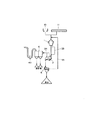
図1は本発明の実施の第1形態である乾式製砂装置のフローシート図、図2は乾式製砂装置に設けた微粉分級機の断面図である。
【0009】
図において、1は破砕機としての竪型衝撃式破砕機で、原料投入ホッパ10又は前工程破砕設備11から原料を受け入れて破砕し、その破砕物を微粉分級機2に搬送するようになっている。
この場合、竪型衝撃式破砕機1の直下に微粉分級機2を配設して、竪型衝撃式破砕機1からそのまま微粉分級機2に破砕物を投入するようにしてもよいし、又、竪型衝撃式破砕機1と微粉分級機2の間に搬送コンベアを設けもよい。
尚、破砕機としては、竪型衝撃式破砕機のほか、例えば、ロールクラッシャやコーンクラッシャを用いることができる。
【0010】
前記微粉分級機2を図2により説明する。
図2において、20は本体で、内部に傾斜状空間が形成された函体に形成され、スプリング(図示せず)により弾性支持されている。
この本体20の下面部には振動手段としての加振機21が連結されている。この加振機21は、その振動方向が本体20と加振機21を合わせたほぼ重心部Gを通り、かつ垂直Yよりも破砕物の移動方向(矢印A方向)に傾くと共に、水平Xよりも上向きに傾くようにしている。
【0011】
本体20の内部には、隣り合う受板22,22の先端部と基端部が重合するように複数の受板22を階段状に配設して、前記加振機21による振動で破砕物を上から下に向けて移動させるように形成された傾斜分級面23が形成されている。
この傾斜分級面23の上面側には分級室24が形成されると共に、傾斜分級面23の裏面側には空気流入室25が形成され、この空気流入室25から分級室24に連通するように各受板22,22間に空気流路Sが形成されている。
そして、各受板22の先端部には、破砕物の移動方向に延長して網状体26が設けられ、前記空気流路Sがこの網状体26の下方に開口するように形成されている。
【0012】
尚、本体20の上端部には前記竪型衝撃式破砕機1からの破砕物を受け入れる投入口27が形成されており、この投入口27から投入された破砕物がガイド板28を経て傾斜分級面23の上端部に供給されるようになっている。
本体20の下端部には排出口29が形成されており、傾斜分級面23を移動してきた破砕物を傾斜分級面23の下端部から落下させて、この排出口29から取り出すようになっている。
又、本体20の上面には分級室24に開口するように排気口30が形成され、この排気口30には微粉等のみを通過させるスクリーン31が取り付けられている。又、本体20の上側端面には空気流入室25内に開口するように空気取入口32が形成されている。
【0013】
従って、この微粉分級機2では、投入口27から投入された破砕物は、ガイド板28を経て傾斜分級面23の上端部に供給され、加振機21による振動で傾斜分級面23上を上から下に向けて移動する。
この傾斜分級面23上での移動に際し、各受板22の先端部から破砕物の移動方向に延長して網状体26が設けられているため、傾斜分級面23を移動する破砕物を、受板22上から引き続き網状体26の上に移動させて、この受板22及び網状体26の上でほぐしながら満遍なく分散させることができる。
そして、空気流入室25内には送風機によって空気取入口32から空気が供給され、この空気が各受板22,22間に形成した空気流路Sを経て分級室24に吹き出される。
このとき、空気流路Sが網状体26の下方に開口して分級室24に連通しているため、空気流路Sから吹き出される空気が網状体26の下方から分級室24内に向けて吹き付けられる。
このように、網状体26の上で分散している破砕物に対して下方から空気が吹き付けられるため、破砕物に含まれている微粉等を分級室24内で効率よく吹き飛ばすことができ、コンクリート用骨材として、又、品質の高い砕砂を得ることができる。
尚、分級室24内に吹き飛ばされた微粉等は、排気口30から空気とともにバクフイルタ等の集塵機4(図1に示す)に吸引収集されて堆積回収され、又、微粉等を取り除いた破砕物は、傾斜分級面23の下端部から落下して排出口29から取り出され、選別機5(図1に示す)に送られる。
【0014】
図1に戻って説明を続ける。
竪型衝撃式破砕機1と微粉分級機2との間には、竪型衝撃式破砕機1で発生した破砕時微粉等を微粉分級機2に送る第1微粉搬送手段33、例えば、ダクトや密閉構造の搬送コンベアが設けられ、又、微粉分級機2と集塵機4の間には、微粉分級機2で除去した分級微粉等を第1微粉搬送手段33からの破砕時微粉等とともに集塵機4に搬送する第2微粉搬送手段34、例えばダクトが設けられている。尚、微粉分級機2から集塵機4へは送風機40による吸引で分級微粉等及び破砕時微粉等が収集されるようになっている。
【0015】
前記選別機5は、微粉分級機2を経た破砕物を篩選別して砂分とオーバーサイズ破砕物に選別して、砂分を回収するためのもので、オーバーサイズ破砕物を竪型衝撃式破砕機1に戻すための搬送手段35、例えば、搬送コンベアを備えている。
【0016】
上記の乾式製砂装置は、竪型衝撃式破砕機1、微粉分級機2、選別機5の順に配設されているため、竪型衝撃式破砕機1で得られた破砕物から微粉等を微粉分級機2で除去したのち、選別機5によって破砕物を砂分とオーバーサイズ破砕物に選別して、砂分を回収することになる。
このように、竪型衝撃式破砕機1で破砕した破砕物からまず先に微粉等を除去するため、以後の工程、特に選別機5への微粉等の供給が減少し、選別機5での粉塵の発生を抑制することができる。
【0017】
又、選別機5により選別されたオーバーサイズ破砕物を竪型衝撃式破砕機1に戻すための搬送手段35を備えているため、この搬送手段35によりオーバーサイズ破砕物を竪型衝撃式破砕機1に戻すことができる。
従って、オーバーサイズ破砕物を竪型衝撃式破砕機1で再度破砕することができ、原料から砂分を回収する製砂率を向させることができる。
【0018】
又、竪型衝撃式破砕機1で発生した破砕時微粉等は第1微粉搬送手段33によって微粉分級機2に送られ、この微粉分級機2で除去した分級微粉等とともに第2微粉搬送手段34によって集塵機4に送られるようになっている。
このように、破砕時微粉等と分級微粉等を一緒にして集塵機4に送ることができるため、破砕時微粉等と分級微粉等を共通の集塵機4で回収することができるし、微粉分級機2で発生する分級微粉等だけでなく、竪型衝撃式破砕機1で発生する破砕時微粉等についても回収できるため、乾式製砂装置全体として粉塵の発生を抑えることができる。
尚、選別機5にも微粉回収手段を設けると、乾式製砂装置のほぼ全体において微粉等を回収することができるようになる。
【0019】
【発明の効果】
以上説明してきたように、本発明の乾式製砂装置(請求項1)にあっては、破砕機で得られた破砕物からまず先に微粉等を除去するため、以後の工程、特に選別機への微粉等の供給が減少し、選別機での粉塵の発生を抑制することができる。
【0020】
又、選別機により選別されたオーバーサイズ破砕物を破砕機に戻すための搬送手段を備えているため、オーバーサイズ破砕物を破砕機で再度破砕することができ、原料から砂分を回収する製砂率を向上させることができる。
【0021】
又、破砕機で発生した破砕時微粉等を微粉分級機で除去した分級微粉等とともに集塵機に送るようにすると(請求項2)、破砕時微粉等と分級微粉等を共通の集塵機で回収することができるし、微粉分級機で発生する分級微粉等だけでなく、破砕機で発生する破砕時微粉等についても回収できるため、乾式製砂装置全体として粉塵の発生を抑えることができる。
【図面の簡単な説明】
【図1】本発明の実施の第1形態である乾式製砂装置のフローシート図である。
【図2】乾式製砂装置に設けた微粉分級機の断面図である。
【符号の説明】
1 竪型衝撃式破砕機(破砕機)
2 微粉分級機
4 集塵機
5 選別機
10 原料投入ホッパ
11 前工程破砕設備
33 第1微粉搬送手段
34 第2微粉搬送手段
35 搬送手段
40 送風機[0001]
TECHNICAL FIELD OF THE INVENTION
The present invention relates to a dry sand making apparatus for selectively collecting crushed sand used as an aggregate for concrete or the like from crushed materials crushed by a crusher.
[0002]
[Prior art]
The dry sand making equipment consists of a crusher that crushes the received raw material, a fine powder classifier that removes fine powder etc. from the crushed material obtained by the crusher, and a crusher that crushes the crushed material obtained by the crusher with sand and oversize. And a sorter for sorting sand and collecting sand.
Conventionally, in this dry sand making apparatus, classification for removing fine powder, unnecessary dust and impurities (hereinafter, referred to as fine powder, etc.) is performed by a method for reducing or avoiding classification efficiency due to adhesion of the crushed material. After being sorted into sand and oversized crushed material.
That is, in the case of the sand making flow sheet, the crushing machine, the sorting machine, and the fine powder classifier were arranged in this order.
[0003]
[Problems to be solved by the invention]
However, as in the past, in a dry sand maker in which a crusher, a sorter, and a fine powder classifier are arranged in this order, a large amount is contained in the crushed material from the crusher through the sorter to the fine powder classifier. The fine powder or the like is exhausted in a connecting portion of a conveyor or the like and particularly in a sorting machine and is diffused into the atmosphere.
In this case, the working environment will be degraded, dust pollution will adversely affect residents near the quarry, and will affect the operation of the quarry.
In addition, before dry sand making was generally performed, most of wet sand making with little generation of dust, but because of the large scale of the equipment and the need for polluted water treatment equipment, There were problems such as an increase in running costs.
[0004]
The present invention has been made to solve such a conventional problem, and it is an object of the present invention to provide a dry sand making apparatus capable of minimizing dust generation, improving a work environment and preventing dust pollution. And
[0005]
[Means for Solving the Problems]
In order to solve the above-mentioned problems, a dry sand making device of the present invention (claim 1)
A crusher that crushes the received raw material, a fine powder classifier that removes fine powder etc. from the crushed material obtained by the crusher, and a crushed material obtained by the crusher are sorted into sand content and oversized crushed material, Equipped with a sorter that collects sand,
The fine powder classifier is disposed between the crusher and the sorter,
The transporting device (for example, a transport conveyor) for returning the oversized crushed material sorted by the sorter to the crusher is provided.
[0006]
The dry sand-making apparatus of the present invention is, in terms of a sand-making flow sheet, arranged in the order of a crusher, a fine powder classifier, and a sorter, so that fine powder and the like can be finely classified from the crushed material obtained by the crusher. After that, the crushed material is sorted into sand and oversized crushed material by a sorter, and the sand is collected.
As described above, since fine powder and the like are first removed from the crushed material obtained by the crusher, it is possible to suppress the generation of dust in subsequent steps, particularly, in the sorter.
Further, since the oversized crushed material can be returned to the crusher by the transporting means, the oversized crushed material can be crushed again by the crusher, and the sand production rate for collecting sand from the raw material can be improved. .
[0007]
Further, in the dry sand making device of the present invention, the first fine powder conveying means for sending fine powder at the time of crushing generated by the crusher to the fine powder classifier, and the classified fine powder removed by the fine powder classifier from the first fine powder conveying means. There is a mode (claim 2) in which a second fine powder transport means is transported to the dust collector together with the fine powder at the time of crushing.
Therefore, the crushed fine powder generated by the crusher is sent to the fine powder classifier by the first fine powder conveying means, and is sent to the dust collector by the second fine powder conveying means together with the classified fine powder removed by the fine powder classifier.
As described above, since the fine powder at the time of crushing and the classified fine powder can be sent to the dust collector together, the fine powder at the time of crushing and the classified fine powder can be collected by the common dust collector, and are generated by the fine particle classifier. Since not only classified fine powders but also fine powders at the time of crushing generated by a crusher can be collected, the generation of dust can be suppressed in the dry sand making apparatus as a whole.
[0008]
BEST MODE FOR CARRYING OUT THE INVENTION
Hereinafter, embodiments of the present invention will be described in detail with reference to the drawings. Note that the specific configuration of the present invention is not limited to the following embodiments.
FIG. 1 is a flow sheet diagram of a dry sand making apparatus according to a first embodiment of the present invention, and FIG. 2 is a sectional view of a fine powder classifier provided in the dry sand making apparatus.
[0009]
In the drawing, reference numeral 1 denotes a vertical impact type crusher as a crusher, which receives and crushes raw materials from a raw
In this case, the fine powder classifier 2 may be disposed immediately below the vertical impact type crusher 1, and the crushed material may be directly input from the vertical impact type crusher 1 to the fine powder classifier 2, A conveyor may be provided between the vertical impact crusher 1 and the fine powder classifier 2.
As the crusher, for example, a roll crusher or a cone crusher can be used in addition to the vertical impact crusher.
[0010]
The fine powder classifier 2 will be described with reference to FIG.
In FIG. 2, reference numeral 20 denotes a main body, which is formed in a box having an inclined space formed therein, and is elastically supported by a spring (not shown).
A
[0011]
Inside the main body 20, a plurality of receiving
A classification chamber 24 is formed on the upper surface side of the
A
[0012]
An inlet 27 for receiving the crushed material from the vertical impact crusher 1 is formed at the upper end of the main body 20, and the crushed material input from the inlet 27 is subjected to the inclined classification through the
A discharge port 29 is formed at the lower end of the main body 20, and the crushed material that has moved on the
An
[0013]
Therefore, in this fine powder classifier 2, the crushed material input from the input port 27 is supplied to the upper end of the
At the time of movement on the
Then, air is supplied into the air inflow chamber 25 from the
At this time, since the air flow path S is opened below the
As described above, air is blown from below onto the crushed material dispersed on the
The fine powder blown into the classifying chamber 24 is sucked and collected by the dust collector 4 (shown in FIG. 1) such as a back filter through the
[0014]
Returning to FIG. 1, the description will be continued.
Between the vertical impact type crusher 1 and the fine powder classifier 2, first fine powder transport means 33 for sending fine powder at the time of crushing generated by the vertical impact type crusher 1 to the fine powder classifier 2, such as a duct or the like. A conveyor having a closed structure is provided, and between the fine powder classifier 2 and the
[0015]
The sorter 5 is for sieving the crushed material that has passed through the fine powder classifier 2 to separate sand and oversized crushed material, and recovering the sand content. The unit is provided with a transporting
[0016]
Since the above-mentioned dry sand making device is arranged in the order of the vertical impact crusher 1, the fine powder classifier 2, and the separator 5, the fine sand and the like can be obtained from the crushed material obtained by the vertical impact crusher 1. After being removed by the fine powder classifier 2, the crushed material is separated into sand and oversized crushed material by the sorter 5, and the sand is collected.
As described above, since fine powder and the like are first removed from the crushed material crushed by the vertical impact crusher 1, the supply of fine powder and the like to the subsequent steps, particularly to the sorter 5, is reduced. Generation of dust can be suppressed.
[0017]
In addition, since the
Therefore, the oversized crushed material can be crushed again by the vertical impact crusher 1, and the sand production rate for recovering sand from the raw material can be improved.
[0018]
Further, the fine powder at the time of crushing generated by the vertical impact type crusher 1 is sent to the fine powder classifier 2 by the first fine
As described above, since the fine powder at the time of crushing and the classified fine powder can be sent to the
In addition, if the fine powder collecting means is provided also in the sorting machine 5, it becomes possible to collect the fine powder and the like in almost the entire dry sand making device.
[0019]
【The invention's effect】
As described above, in the dry sand-making apparatus of the present invention (claim 1), in order to first remove fine powder and the like from the crushed material obtained by the crushing machine, the subsequent steps, particularly the sorting machine The supply of fine powder and the like to the powder is reduced, and the generation of dust in the sorting machine can be suppressed.
[0020]
In addition, since there is provided a conveying means for returning the oversized crushed material sorted by the sorting machine to the crusher, the oversized crushed material can be crushed again by the crusher, and the sand is recovered from the raw material. Sand rate can be improved.
[0021]
In addition, if the fine powder etc. at the time of crushing generated by the crusher is sent to the dust collector together with the classified fine powder removed by the fine powder classifier (Claim 2), the fine powder at the time of crushing and the classified fine powder should be collected by the common dust collector. In addition, not only the classified fine powder generated by the fine classifier but also the fine powder during crushing generated by the crusher can be collected, so that the generation of dust can be suppressed in the dry sand making apparatus as a whole.
[Brief description of the drawings]
FIG. 1 is a flow sheet diagram of a dry sand making device according to a first embodiment of the present invention.
FIG. 2 is a sectional view of a fine powder classifier provided in the dry sand making device.
[Explanation of symbols]
1 Vertical impact crusher (crusher)
2
Claims (2)
前記微粉分級機が破砕機と選別機の間に配設され、
選別機により選別されたオーバーサイズ破砕物を破砕機に戻すための搬送手段を備えていることを特徴とする乾式製砂装置。A crusher that crushes the received raw material, a fine powder classifier that removes fine powder etc. from the crushed material obtained by the crusher, and a crushed material obtained by the crusher are sorted into sand content and oversized crushed material, Equipped with a sorter that collects sand,
The fine powder classifier is disposed between the crusher and the sorter,
A dry sand maker comprising a transporting means for returning the oversized crushed material sorted by the sorter to the crusher .
Priority Applications (1)
| Application Number | Priority Date | Filing Date | Title |
|---|---|---|---|
| JP2000323935A JP3579343B2 (en) | 2000-10-24 | 2000-10-24 | Dry sand making equipment |
Applications Claiming Priority (1)
| Application Number | Priority Date | Filing Date | Title |
|---|---|---|---|
| JP2000323935A JP3579343B2 (en) | 2000-10-24 | 2000-10-24 | Dry sand making equipment |
Publications (2)
| Publication Number | Publication Date |
|---|---|
| JP2002126563A JP2002126563A (en) | 2002-05-08 |
| JP3579343B2 true JP3579343B2 (en) | 2004-10-20 |
Family
ID=18801542
Family Applications (1)
| Application Number | Title | Priority Date | Filing Date |
|---|---|---|---|
| JP2000323935A Expired - Fee Related JP3579343B2 (en) | 2000-10-24 | 2000-10-24 | Dry sand making equipment |
Country Status (1)
| Country | Link |
|---|---|
| JP (1) | JP3579343B2 (en) |
Families Citing this family (5)
| Publication number | Priority date | Publication date | Assignee | Title |
|---|---|---|---|---|
| JP4485950B2 (en) * | 2002-10-18 | 2010-06-23 | 昭和電工株式会社 | Dry pulverization apparatus and dry pulverization method |
| JP5090684B2 (en) * | 2005-08-01 | 2012-12-05 | 日清製粉株式会社 | Production method of whole wheat flour |
| CN112536132A (en) * | 2020-11-18 | 2021-03-23 | 中国水利水电第九工程局有限公司 | Machine-made sand shell breaking and core retaining desliming system and desliming process thereof |
| CN112892814A (en) * | 2020-12-24 | 2021-06-04 | 中国水利水电第九工程局有限公司 | Pneumatic powder removing process in manual sand making process |
| CN112808424A (en) * | 2020-12-30 | 2021-05-18 | 奉节县勇立建材有限公司 | Rubble system of processing |
-
2000
- 2000-10-24 JP JP2000323935A patent/JP3579343B2/en not_active Expired - Fee Related
Also Published As
| Publication number | Publication date |
|---|---|
| JP2002126563A (en) | 2002-05-08 |
Similar Documents
| Publication | Publication Date | Title |
|---|---|---|
| KR100544233B1 (en) | Manufacturing method and apparatus of recycling construction waste aggregate having air circulation type removing apparatus of impurity and dust | |
| JP4629301B2 (en) | Unit for cleaning waste containing wood | |
| CN206382060U (en) | A kind of raw coal crushing-separating apparatus | |
| JPH0651176B2 (en) | Equipment for dry cleaning of granular food and feed and separation of various pieces | |
| CN210876288U (en) | Rice screening plant | |
| CN109454001A (en) | A kind of vibration winnowing device | |
| JP3579343B2 (en) | Dry sand making equipment | |
| CN110124996A (en) | Energy-saving air-flow powder concentrator | |
| CN108607671A (en) | A kind of building waste dry type taxonomic revision method | |
| US20060243830A1 (en) | Auto shredder air scrubber | |
| JP2000237687A (en) | Crushed sand classifier | |
| CN100463731C (en) | Tobacco granular material cleaner | |
| JP4182049B2 (en) | Wind sorter | |
| JP3919698B2 (en) | Aggregate fine powder removal device | |
| CN106475321A (en) | Proportion dressing machine | |
| JP3523621B2 (en) | Crushed sand fine powder classifier | |
| JP2003053269A (en) | Classifier for fine particle of crushed sand | |
| CN220111635U (en) | Building rubbish vibration screening winnowing system | |
| JPH0373351B2 (en) | ||
| JP4355086B2 (en) | Dust remover for rocking grinder | |
| JP2005329346A (en) | Pneumatic separator | |
| CN216137678U (en) | Large-scale casing dust collector for screening machine | |
| CN220590768U (en) | Fine particulate matter selection by winnowing dust collector | |
| JP3615503B2 (en) | Crushed sand fine powder classifier | |
| JP3492621B2 (en) | Crushed sand fine powder classifier |
Legal Events
| Date | Code | Title | Description |
|---|---|---|---|
| A131 | Notification of reasons for refusal |
Free format text: JAPANESE INTERMEDIATE CODE: A131 Effective date: 20031216 |
|
| A602 | Written permission of extension of time |
Free format text: JAPANESE INTERMEDIATE CODE: A602 Effective date: 20040302 |
|
| A521 | Written amendment |
Free format text: JAPANESE INTERMEDIATE CODE: A523 Effective date: 20040323 |
|
| TRDD | Decision of grant or rejection written | ||
| A01 | Written decision to grant a patent or to grant a registration (utility model) |
Free format text: JAPANESE INTERMEDIATE CODE: A01 Effective date: 20040615 |
|
| A61 | First payment of annual fees (during grant procedure) |
Free format text: JAPANESE INTERMEDIATE CODE: A61 Effective date: 20040715 |
|
| R150 | Certificate of patent or registration of utility model |
Free format text: JAPANESE INTERMEDIATE CODE: R150 |
|
| R250 | Receipt of annual fees |
Free format text: JAPANESE INTERMEDIATE CODE: R250 |
|
| FPAY | Renewal fee payment (event date is renewal date of database) |
Free format text: PAYMENT UNTIL: 20090723 Year of fee payment: 5 |
|
| FPAY | Renewal fee payment (event date is renewal date of database) |
Free format text: PAYMENT UNTIL: 20100723 Year of fee payment: 6 |
|
| FPAY | Renewal fee payment (event date is renewal date of database) |
Free format text: PAYMENT UNTIL: 20110723 Year of fee payment: 7 |
|
| FPAY | Renewal fee payment (event date is renewal date of database) |
Free format text: PAYMENT UNTIL: 20120723 Year of fee payment: 8 |
|
| FPAY | Renewal fee payment (event date is renewal date of database) |
Free format text: PAYMENT UNTIL: 20120723 Year of fee payment: 8 |
|
| FPAY | Renewal fee payment (event date is renewal date of database) |
Free format text: PAYMENT UNTIL: 20130723 Year of fee payment: 9 |
|
| LAPS | Cancellation because of no payment of annual fees |