JP3578552B2 - Data communication system and terminal-side data communication device - Google Patents
Data communication system and terminal-side data communication device Download PDFInfo
- Publication number
- JP3578552B2 JP3578552B2 JP13519296A JP13519296A JP3578552B2 JP 3578552 B2 JP3578552 B2 JP 3578552B2 JP 13519296 A JP13519296 A JP 13519296A JP 13519296 A JP13519296 A JP 13519296A JP 3578552 B2 JP3578552 B2 JP 3578552B2
- Authority
- JP
- Japan
- Prior art keywords
- data communication
- communication device
- side data
- terminal
- host
- Prior art date
- Legal status (The legal status is an assumption and is not a legal conclusion. Google has not performed a legal analysis and makes no representation as to the accuracy of the status listed.)
- Expired - Fee Related
Links
Images


Landscapes
- Meter Arrangements (AREA)
- Data Exchanges In Wide-Area Networks (AREA)
- Telephonic Communication Services (AREA)
Description
【0001】
【発明の属する技術分野】
本発明は、公衆電話回線等、課金パルスが発生することによって料金回収がなされる電話回線を用いて行うデータ通信に関するものである。
【0002】
【従来の技術】
例えば、公衆電話機用の電話回線を利用したデータ伝送においては、料金回収のための課金パルスが発生することによって、通信データに欠落やデータ化けを生じることがある。このような通信データの欠落やデータ化けに対してデータの再送をする必要が生じる。その場合、データの再送を最小限に留めることを目的として、送信データを一定の小さなサイズ(ブロック)に区切って転送を行うことが考えられていた。
【0003】
また、別の制御方式としては特開平2−90865号公報に開示されているように、課金パルスの発生周期を取得し、課金パルスの発生タイミングでデータ送信又はデータ受信を一時停止することも考えられていた。
このように、従来は課金パルスが発生することを前提とし、その課金パルスの影響をいかに防止するかを主要観点としたデータ転送方法が考えられていた。
【0004】
【発明が解決しようとする課題】
しかしながら、送信データを一定の小さなブロックに区切って転送を行うと、送信する総ブロック数が多くなることで、ブロック化に要する負担やブロック単位で必要となる応答処理に関する負担も大きくなり、転送効率の低下を招くことになる。また、課金パルスの発生周期を取得し、課金パルスの発生タイミングでデータ送受信を一時的に停止する方法を用いた場合には、停止している時間が余分にかかり、特に長距離の通信では課金パルスが頻繁に発生するため転送時間が大幅に増大することになる。
【0005】
本発明は、上述した問題点を解決するためになされたものであり、課金パルスの発生を無くし、データの欠落やデータ化け等のデータ通信エラーの発生及びデータ転送時間の増加を防ぐことを目的とする。
【0006】
【課題を解決するための手段及び発明の効果】
請求項1に記載のデータ通信システムは、発呼処理を行って回線を接続すると課金パルスが発生する電話回線に接続されている可能性のある端末側データ通信装置と、発呼処理を行って回線を接続すると課金パルスが発生しない電話回線に接続されているホスト側データ通信装置との間でデータ通信を行うデータ通信システムにおいて、前記端末側データ通信装置は、課金パルスを検出するための課金パルス検出手段を備え、前記ホスト側データ通信装置を発呼し回線を接続した際に、前記課金パルス検出手段によって課金パルスを検出したときには、前記ホスト側データ通信装置に折り返し発呼させるための折り返し発呼要求を送信し、回線を切断して該ホスト側データ通信装置からの発呼を待つよう構成され、一方、前記ホスト側データ通信装置は、前記端末側データ通信装置より前記折り返し発呼要求を受信すると、一旦回線の切断を行った後、所定のタイミングで該当する端末側データ通信装置を発呼してデータ通信を行うよう構成されていることを特徴としている。
【0007】
本データ通信システムは、公衆電話機やいわゆるピンク電話機等が接続されるような電話回線、すなわち発呼処理をして回線を接続すると課金パルスの発生するような電話回線に接続されている可能性のある端末側データ通信装置と、宅内の一般電話機等が接続されるような電話回線、すなわち発呼処理をして回線を接続しても課金パルスの発生しないような電話回線に接続されているホスト側データ通信装置との間でデータ通信を行うものである。この場合、ホスト側データ通信装置から端末側データ通信装置を発呼する場合には課金パルスは発生しないために問題はない。
【0008】
しかし、端末側データ通信装置がホスト側データ通信装置を発呼するときには、課金パルスが発生する可能性がある。この問題に対して本発明では、端末側データ通信装置が課金パルスの発生を検出すると、端末側データ通信装置はホスト側データ通信装置に折り返し発呼するよう要求する。その結果、課金パルスの発生しない電話回線に接続されたホスト側データ通信装置が端末側データ通信装置を発呼しなおす。これによって、課金パルスの発生を防止する。
【0009】
次にその作用を詳しく説明する。最初に端末側データ通信装置がホスト側データ通信装置を発呼し回線を接続する。このとき、接続された回線に課金パルスが発生する可能性がある。そして、課金パルス検出手段によって課金パルスが検出されなかった場合は通常のデータ通信を行うが、課金パルスが検出された場合、端末側データ通信装置は、ホスト側データ通信装置から発呼しなおさせるための折り返し発呼要求をホスト側データ通信装置へ送信する。折り返し発呼要求にはホスト側データ通信装置がその要求を送信した端末側データ通信装置を発呼しなおすための情報、例えば端末側データ通信装置の電話番号等が含まれている。端末側データ通信装置は、折り返し発呼要求を送信することでホスト側データ通信装置からの発呼のしなおしを要求すると、例えばオンフック等の回線の切断処理をしてホスト側データ通信装置からの発呼を待つ。
【0010】
一方、ホスト側データ通信装置は、端末側データ通信装置が送信した折り返し発呼要求を受信すると、例えばオンフック等を行うことによって回線を切断した後、折り返し発呼要求を送信した端末側データ通信装置を発呼し回線を接続する。そして、その端末側データ通信装置との間でデータ通信を行う。
【0011】
これによって、データの欠落やデータ化けを防止できる。また、データ再送要求を最小限に留めるために、転送データを細かく区切ったり、データの送受信を課金パルスに合わせて停止したりするような課金パルス回避のための処理を施す必要がなくなるため、転送速度の低下も起こらない。
【0012】
請求項1に記載の「所定のタイミング」というのは、ホスト側端末装置が折り返し発呼要求を受信し回線を切断した直後でもよいし、あるいは、請求項2及び3に示すように所定の処理を行った後でもよい。
ところで、端末側データ通信装置及びホスト側データ通信装置は共にオンフック等の回線切断処理を行うが、どちらのデータ通信装置が先に回線切断処理を行ってもよい。その結果、先に回線切断処理を行ったデータ通信装置によって通信回線は切断されることになる。
【0013】
なお、このような構成のデータ通信システムにおける回線使用料金は、端末側データ通信装置からホスト側データ通信装置を発呼してデータ通信を行う場合、端末側データ通信装置側が回線の使用料金を支払うのが普通である。しかし本発明のデータ通信システムでは、上述のように課金パルスの発生を無くすために、ホスト側データ通信装置から端末側データ通信装置を発呼しなおすようにしている。そのため、普通は支払う必要のないホスト側データ通信装置側に回線使用料金が課金されることになるが、ホスト側データ通信装置は、例えばビデオテックスシステム等を用いて回線の使用料金を回収することが可能である。
【0014】
また、上記ピンク電話等の接続される公衆回線の使用料が宅内電話機等の接続される一般回線の使用料よりも高額となっている現状を考えると、一般回線に接続されているホスト側データ通信装置から端末側データ通信装置を発呼してデータ通信を行うことは、ホスト側データ通信装置側には回線使用料金の回収作業が発生するものの使用料金を支払う端末側データ通信装置側にとって現状では有利と考えられる。
【0015】
ところで、このようなデータ通信システムとしては、例えばホスト側データ通信装置1台に対して端末側データ通信装置が複数台設けられているというようなシステムが考えられる。例えば、ホスト側データ通信装置が情報共有の場となり複数の端末側データ通信装置からアクセスされるような状況等が考えられる。このようなシステムにおいては、端末側データ通信装置からの折り返し発呼要求をホスト側データ通信装置が受信した直後に、折り返し発呼要求を送信した端末側データ通信装置を発呼しデータ通信を行う構成とした場合には、別の端末側データ通信装置はデータ通信終了までアクセスすることができないという状況が起こり得る。
【0016】
このような状況を解決するために請求項2に示すような構成が有効である。すなわち、ホスト側データ通信装置は、さらに、受信した折り返し発呼要求を記憶する発呼要求記憶手段と、発呼要求記憶手段に折り返し発呼要求が記憶されている場合、回線の切断時には別の端末側データ通信装置からの発呼の有無を判断する発呼有無判断手段とを備え、発呼有無判断手段によって別の端末側データ通信装置からの発呼が有ると判断された場合は、その別の端末側データ通信装置との間に回線を接続し、一方、発呼有無判断手段によって別の端末側データ通信装置からの発呼が無いと判断された場合は、発呼要求記憶手段に記憶された折り返し発呼要求の中で、該当する端末側データ通信装置への発呼がなされておらず、かつ最も古い時点で記憶された折り返し発呼要求に該当する端末側データ通信装置を発呼してデータ通信を行うという構成である。
【0017】
この場合、ホスト側データ通信装置は、端末側データ通信装置より送信された折り返し発呼要求を発呼要求記憶手段に記憶しておく。そして、回線の切断時点で発呼要求記憶手段に折り返し発呼要求が記憶されているときには、発呼有無判断手段によって常に別の端末側データ通信装置からの発呼の有無を判断する。ここで、別の端末側データ通信装置からの発呼が有る場合には、先にその別の端末側データ通信装置に応答してその別の端末側データ通信装置との間でデータ通信を行う。その別の端末側データ通信装置がさらに折り返し発呼要求を送信した場合は、この折り返し発呼要求も発呼要求記憶手段に記憶して回線を切断する。この時点でさらに上記2台の端末側データ通信装置とは別の端末側データ通信装置からの発呼があった旨を発呼有無判断手段によって判断した場合には、さらにその端末側データ通信装置との間でデータ通信を行う。
【0018】
一方、別の端末側データ通信装置からの発呼が無い場合に限り、発呼要求記憶手段に記憶された折り返し発呼要求に基づき、折り返し発呼要求を送信した端末側データ通信装置をホスト側データ通信装置から発呼しなおしてデータ通信を行う。また、折り返し発呼要求が複数記憶されている場合には、ホスト側データ通信装置からまだ折り返し発呼していない端末側データ通信装置の送信した折り返し発呼要求の中で、最も古くから記憶されている折り返し発呼要求を処理する。つまり、ホスト側データ通信装置からの発呼を要求しそのホスト側データ通信装置からの発呼を最も長い間待っている端末側データ通信装置を発呼する。このように、折り返し発呼の要求が複数記憶された場合、その要求が記憶された順に端末側データ通信装置を発呼する。その端末側データ通信装置とのデータ通信が終了し回線を切断した時点では、また別の端末側データ通信装置からの発呼の有無を発呼有無判断手段が判断して上述の処理を繰り返す。
【0019】
このように、ある端末側データ通信装置との回線を切断したときには、毎回他の端末側データ通信装置からの発呼を検出することで、複数の端末側データ通信装置がホスト側データ通信装置へアクセスできる機会を増やすことができる。
また、請求項1に示したように、課金パルスによる転送効率の低下が起こらないため1台の端末側データ通信装置がホスト側データ通信装置を占有する時間も短くなる。よって、ホスト側データ通信装置が頻繁にアクセスされるシステムでは、例えば1日の間にデータ通信できる端末側データ通信装置の台数も増加することができ、また、端末側データ通信装置からホスト側データ通信装置をアクセスできる機会も増加することができるので望ましい。
【0020】
ところで、上記請求項2に示した構成において、ある端末側データ通信装置が折り返し発呼要求を送信してから、別の端末側データ通信装置からの発呼が続くといつまで経ってもホスト側データ通信装置から折り返しの発呼がされないという状況が起きることも考えられる。
【0021】
そこで請求項3に示すデータ通信システムは、このような状況も解決しようとするものである。すなわち、そのデータ通信システムは、前記発呼有無判断手段によって別の端末側データ通信装置からの発呼が有ると判断された場合であっても、該当する端末側データ通信装置への発呼がなされていない折り返し発呼要求の中で最も古い折り返し発呼要求が記憶された時点から所定時間が経過している場合には、該折り返し発呼要求を送信した端末側データ通信装置を発呼しデータ通信を行うよう構成されていることを特徴としている。
【0022】
この場合、ホスト側データ通信装置は、発呼有無判断手段によって別の端末側データ通信装置からの発呼が有ると判断されたときでも、折り返し発呼要求を送信してから所定時間ホスト側データ通信装置からの発呼を待っている端末側データ通信装置があるときには、その端末側データ通信装置を発呼してデータ通信を行う。
【0023】
これによって、別の端末側データ通信装置からの発呼が続く場合であっても、折り返し発呼要求を送信した端末側データ通信装置は、所定時間内に必ずホスト側データ通信装置からの発呼を受け、データ通信を行うことができる。
【0024】
【0025】
【0026】
また、上述のデータ通信システムで有効となる端末側データ通信装置は、請求項4に示すように、発呼処理を行って回線を接続すると課金パルスが発生する電話回線に接続されている可能性のある端末側データ通信装置において、送信された折り返し発呼要求を受信して前記端末側データ通信装置を発呼することが可能なホスト側データ通信装置との間でデータ通信が可能であり、課金パルスを検出するための課金パルス検出手段を備え、前記ホスト側データ通信装置を発呼し回線を接続した際に、前記課金パルス検出手段によって課金パルスを検出したときには、前記ホスト側データ通信装置に折り返し発呼させるための折り返し発呼要求を送信し、回線を切断して該ホスト側データ通信装置からの発呼を待つよう構成されていることを特徴としている。
【0027】
この端末側データ通信装置における動作については、上述したデータ通信システムの動作の説明中において説明しているので、ここでは省略する。
【0028】
【発明の実施の形態】
以下、本発明を具体化した一実施形態を図面を参照して説明する。
図1は本実施形態のデータ通信システム1の概略構成を示すブロック図である。データ通信システム1は、「端末側データ通信装置」としての端末側データ通信装置10と、「ホスト側データ通信装置」としてのホスト側データ通信装置20とから構成されている。端末側データ通信装置10は、課金パルスが発生する電話回線又は課金パルスの発生しない電話回線のどちらにも接続できる。そして、ホスト側データ通信装置20を発呼すると、課金パルスの発生する公衆電話回線40又は課金パルスの発生しない一般電話回線30のいずれかで接続される。一方、ホスト側データ通信装置20は、発呼処理を行って回線を接続した場合には必ず課金パルスの発生しない一般電話回線30で接続されるような電話回線に接続しておく。
【0029】
なお、ホスト側データ通信装置20は、後述するように複数台の端末側データ通信装置10によって交替でアクセスされるものとする。
次に、端末側データ通信装置10及びホスト側データ通信装置20の構成を説明する。端末側データ通信装置10とホスト側データ通信装置20とはよく似た構成をしている。
【0030】
そこで、最初に上記端末側データ通信装置10とホスト側データ通信装置20に共通する構成要素を説明する。共通の構成要素として、制御手段としてのCPU11(21)と、ワークエリア等のための一時記憶手段としてのRAM12(22)と、プログラム記憶手段としてのROM13(23)と、データの変調及び復調を行うモデム14(24)と、網との回線の接続/切断、及びダイヤルを行うNCU(Network Control Unit:網制御装置)15(25)とを備えている。ここで、()書きの数字はホスト側データ通信装置20の構成要素に付けられた符号である。なお、ホスト側データ通信装置20のCPU21は、「発呼有無判断手段」に相当する。
【0031】
次に、上記端末側データ通信装置10とホスト側データ通信装置20で相違する構成要素を説明する。まず端末側データ通信装置10は、課金パルスの有無を検出する「課金パルス検出手段」としての課金パルス検出回路16を備えている。一方、ホスト側データ通信装置20は、端末側データ通信装置より送信される「折り返し発呼要求」を記憶するための「発呼要求記憶手段」としてのメモリ装置26を備えている。
【0032】
ここで、本実施形態のデータ通信システム1の動作を図2、図3、図4のフローチャートに基づいて説明する。
図2は、端末側データ通信装置10の作用を示すフローチャートである。
本発明は、端末側データ通信装置10から発呼した場合における課金パルスの発生したデータ通信の防止を目的とするものであるため、端末側データ通信装置10がホスト側データ通信装置20を発呼する場合を考える。
【0033】
まず、最初のステップS100においてオフフックを行い、回線の接続準備をする。次に、S110ではホスト側データ通信装置20へダイヤルし、ホスト側データ通信装置20を発呼して回線を接続する。回線の接続が完了すると、S120では、課金パルス検出の準備として課金パルスの検出結果を代入するフラグKを0として初期化する。次にS130で割込処理の許可をする。この割込処理が許可されることにより初めて課金パルス検出回路からの信号により割込処理が行われる。
【0034】
ここで、図5のフローチャートに基づき、端末側データ通信装置10の課金パルス検出回路16によって課金パルスが検出された場合に行われる割込処理について説明する。この割込処理は課金パルス検出回路16からの信号によって、端末側データ通信装置10のCPU11が実行する。
【0035】
最初のステップS500で課金パルス検出結果のフラグK=1(課金パルスが検出された状態を表す)とする。そして、一度課金パルスを検出したときには、この割込処理が起こらないようにS510で割込処理を禁止し処理を終了する。 次に、図2の説明に戻る。S140〜S160の処理でデータの送受信を行う。S140では、データ送受信をブロック単位(複数バイト単位)で行う。そして、S160でデータ送受信の完了を判断する。S160でデータ送受信の完了が判断されなければ(S160:NO)、S140へ移行し次のデータブロックの送受信を行う。
【0036】
S150では、S140のデータ送受信処理でブロック単位のデータが送信又は受信される毎にフラグK=1か否か(課金パルスが検出されたか)を判断する。K=1でない場合(S150:NO)、すなわち課金パルスが検出されていない場合、S160へ移行してデータ送受信を続ける。フラグK=1である場合(S150:YES)、すなわち課金パルスが検出された場合には、S140〜S160のデータ送受信処理を中断してS190へ移行する。
【0037】
課金パルスが検出されず(常にS150でK=0)、S160でデータの送受信の完了が判断されると(S160:YES)、S170へ移行し割込処理を禁止してS180でオンフックを行い回線を切断する。この場合、従来からあったデータ送受信と同様の処理となる。
【0038】
課金パルスを検出した場合、S190において端末側データ通信装置10は折り返し発呼要求をホスト側データ通信装置20へ送信する。そして、S200でオンフックを行い一旦回線を切断する。次に、S210では、送信した折り返し発呼要求に対するホスト側データ通信装置20からの折り返しの発呼があるかを判断する。ホスト側データ通信装置20からの折り返しの発呼がある場合(S210:YES)は、S220へ移行する。ホスト側データ通信装置からの折り返しの発呼がない場合(S210:NO)は、ホスト側データ通信装置から折り返し発呼されるまでS210の判断を繰り返す。
【0039】
ホスト側データ通信装置20から折り返し発呼された場合、S220でオフフックを行いホスト側データ通信装置20からの折り返しの発呼に対して回線を接続する。その後、S230及びS240の処理を繰り返しデータ送受信を行う。S230では、ブロック単位でデータの送信又は受信を行い、S240では、データ送受信の完了を判断する。データ送受信が完了していない場合(S240:NO)、再びS230へ移行し、次のデータブロックを送信又は受信する。データ送受信が完了した場合(S240:YES)、S250でオンフックを行い回線を切断して処理を終了する。
【0040】
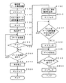
次に、図3及び図4のフローチャートに基づいて、ホスト側データ通信装置20のメイン処理について説明する。メイン処理は図2のフローチャートに基づいて説明した端末側データ通信装置10からの発呼に対応して行われる処理である。
【0041】
まず、最初のステップS310では、端末側データ通信装置10からの発呼があるかを判断する。端末側データ通信装置10からの発呼がない場合(S310:NO)は、端末側データ通信装置10からの発呼があると判断されるまでこの処理を続ける。ここで図2中のS100及びS110の処理によって端末側データ通信装置10から発呼された場合(S310:YES)、S320でオフフックを行い、端末側データ通信装置10からの発呼に対して回線を接続する。
【0042】
回線接続後、S330〜S350でデータ送受信を行う。この処理は、図2における端末側データ通信装置10のS140〜S160のデータ送受信処理に対応して行われるデータ送受信処理である。S330では、所定のブロック単位でデータの送信及び受信が行われる。そして、S340では、端末側データ通信装置10から図2中のS190の処理によって送信された折り返し発呼要求を受信したかをブロック単位のデータ送受信毎に判断する。折り返し発呼要求を受信した場合(S340:YES)、S360へ移行して受信した折り返し発呼要求を図1の示すメモリ装置26に記憶し、S370でオンフックを行い、データ送受信の途中で一旦回線を切断する。折り返し発呼要求を受信しない場合(S340:NO)、データ送受信が完了しないうちは(S350:NO)データの送受信(S330)を続ける。そして、S350において、データ送受信が完了したと判断された場合(S350:YES)、S370でオンフックを行い回線を切断する。なお、データ送受信が完了したと判断された場合(S350:YES)は、端末側データ通信装置10によって課金パルスが検出されなかった場合であり、従来からあったデータ通信と同様の処理を行ったことになる。
【0043】
続く処理は、図4に示すS380へ移行する。S380では図1の示すメモリ装置26に折り返し発呼要求が記憶されているかを判断する。メモリ装置26に折り返し発呼要求が記憶されていない場合(S380:NO)、図3のS310からの処理を繰り返す。一方、メモリ装置26に折り返し発呼要求が記憶されている場合(S380:YES)、S390へ移行する。
【0044】
S390では、メモリ装置26に記憶された折り返し発呼要求のうち、ホスト側データ通信装置20が折り返し発呼していない端末側データ通信装置10から送信された折り返し発呼要求で、所定時間が経過しているものがあるかを判断する。例えば、本実施形態ではその所定時間は1時間であるとする。この場合、S390では、ある端末側データ通信装置10から送信され記憶した折り返し発呼要求で、かつ未発呼の折り返し発呼要求の中で記憶してから1時間が経過するような折り返し発呼要求があるかを判断する。記憶してから1時間が経過した未発呼の折り返し発呼要求がある場合(S390:YES)、S410へ移行する。記憶されてから1時間が経過した未発呼の折り返し発呼要求がない場合(S390:NO)、S400へ移行する。
【0045】
S400では、折り返し発呼要求を送信した端末側データ装置10以外の別の端末側データ通信装置10からの発呼があるかを判断する。このとき、別の端末側データ通信装置10からの発呼がある場合(S400:YES)は、図3のS320へ移行してその別の端末側データ通信装置10との間でデータ通信を行う。別の端末側データ通信装置10からの発呼がない場合(S400:NO)は、S410へ移行する。
【0046】
S410ではオフフックを行い、折り返し発呼要求を送信した端末側データ通信装置10を折り返し発呼する準備をする。このとき、S390で肯定判断されている場合には、別の端末側データ通信装置10からの発呼がある可能性があり、その場合にはダイヤル操作ができない。そこで、S412では、ダイヤルトーンを検出したかを判断する。ダイヤルトーンを検出しなかった場合(S412:NO)、すなわち別の端末側データ通信装置10からの発呼がある場合には、S414へ移行してオンフックを行い、S416にて2秒間待ってS410からの処理を繰り返す。一方、ダイヤルトーンを検出した場合(S412:YES)、すなわち別の端末側データ通信装置10からの発呼がない場合には、S420へ移行する。続くS420では、メモリ装置26に記憶された未発呼の折り返し発呼要求の中で最も古い時点で記憶された折り返し発呼要求を送信した端末側データ通信装置10を発呼する。このとき、折り返し発呼要求を送信した端末側データ通信装置10は、回線を切断し(図2中のS200)、ホスト側データ通信装置20からの折り返しの発呼を待っている(図2中のS210)。従って、ホスト側データ通信装置20が発呼すると、端末側データ通信装置10はオフフックを行う(図2中のS220)。これによって、ホスト側データ通信装置20の発呼(S420)に対して回線が接続される。
【0047】
S430及びS440ではデータの送受信を行う。このデータ送受信処理は図2中のS230及びS240の端末側データ通信装置10のデータ送受信処理に対応している。S430ではブロック単位のデータ送受信を行い、S440ではデータ送受信の完了を判断する。データ送受信が完了していない場合(S440:NO)は、S430へ移行し、S430及びS440のデータ送受信を繰り返す。データ送受信が完了した場合(S440:YES)は、S450でオンフックし回線を切断した後、S380からの処理を繰り返す。
【0048】
以上説明したように、端末側データ通信装置10がホスト側データ通信装置20を発呼し回線を接続して課金パルスが発生した場合、端末側データ通信装置10は折り返し発呼要求をホスト側データ通信装置20へ送信し(図2中のS190)、ホスト側データ通信装置から折り返し発呼されるのを待つ(図2中のS210)。一方、ホスト側データ通信装置20は、その折り返し発呼要求を受信すると、メモリ装置26に記憶し(図3中のS360)、記憶した折り返し発呼要求に該当する端末側データ通信装置10を発呼して(図3中のS420)データ送受信を行う。このとき、上述のようにホスト側データ通信装置20は、発呼処理を行って回線を接続しても課金パルスの発生しない電話回線に接続されているために、ホスト側データ通信装置20が端末側データ通信装置10を折り返し発呼して回線を接続した場合には、必ず課金パルスの発生しない一般電話回線30で接続される。これによって、課金パルスの発生を防止することができ、データの欠落やデータ化けを防止できる。また、従来考えられていたような課金パルス回避のための処理、例えば、データ再送要求を最小限に留めるために転送データを細かく区切ったり、データの送受信を課金パルスに合わせて停止したりするような処理を施す必要がなくなるため、転送速度の低下も起こらない。
【0049】
なお、本発明のデータ通信システム1では、上述のように課金パルスの発生を無くすために、ホスト側データ通信装置20から端末側データ通信装置10を折り返し発呼しなおすようにしている。そのため、普通は支払う必要のないホスト側データ通信装置20側に回線使用料金が課金されることになるが、ホスト側データ通信装置20は、例えばビデオテックスシステム等を用いて回線の使用料金を回収することが可能である。また、ピンク電話機等から発呼した場合に接続される公衆電話回線40の使用料金が宅内電話機等から発呼した場合に接続される一般電話回線30の使用料よりも高額となっている現状を考えると、発呼処理をすると一般電話回線30で接続されるホスト側データ通信装置20から端末側データ通信装置10を発呼してデータ通信を行うことは、ホスト側データ通信装置20側に回線使用料金の回収作業が発生するものの、使用料金を支払う端末側データ通信装置10側にとって現状では有利と考えられる。
【0050】
ところで、本実施形態のデータ通信システム1では、1台のホスト側データ通信装置20に対して、複数台の端末側データ通信装置10がアクセスすることを前提としている。そこで本実施形態のホスト側データ通信装置20では、図3に示したS390及びS400の処理において複数台の端末側データ通信装置10からのアクセスに対する以下( 1 )及び( 2 )に示す工夫を行っている。
【0051】
( 1 )上述のようなデータ通信システム1では、ある1台の端末側データ通信装置10によってホスト側データ通信装置20が占有された場合には、別の端末側データ通信装置10はなかなかアクセスできないという状況が起こり得る。
そこで、本実施形態のホスト側データ通信装置20では、ある端末側データ通信装置10からの折り返し発呼要求をメモリ装置26に記憶しておき(S360)、別の端末側データ通信装置10からの発呼があるかどうかを判断する(S400)。そして、別の端末側データ通信装置10からの発呼がある場合には、その別の端末側データ通信装置10との間に回線を接続してデータ通信を行う。これによって、別の端末側データ通信装置10がホスト側データ通信装置20に対してアクセス可能な機会を増やすことができる。
【0052】
( 2 )また、別の端末側データ通信装置10からの発呼が連続すると、折り返し発呼要求を送信して(図2中のS190)ホスト側データ通信装置20からの発呼を待っている(図2中のS210)端末側データ通信装置10がいつまで経っても折り返し発呼されないという状況が考えられる。
【0053】
そのため、さらに、本実施形態のホスト側データ通信装置20では、メモリ装置26に記憶された折り返し発呼要求の中で1時間が経過しても未発呼の折り返し発呼要求がある場合にはそれを判断し(S390)、別の端末側データ通信装置10への応答に優先して、その折り返し発呼要求に該当する端末側データ通信装置10を折り返し発呼する。これによって、別の端末側データ通信装置10から発呼が連続して起こった場合であっても、折り返し発呼要求を送信した端末側データ通信装置10は、長くても1時間のうちには必ずホスト側データ通信装置20から折り返し発呼されることになり、データ通信を行うことができる。
以上、本発明はこのような実施形態に何等限定されるものではなく、本発明の主旨を逸脱しない範囲において種々なる形態で実施し得る。
【0054】
例えば、上記実施形態では、複数の端末側データ通信装置10から頻繁にアクセスされるようなホスト側データ通信装置20とから構成されるデータ通信システム1を考えたが、複数の端末側データ通信装置10からのアクセスが頻繁にはされないようなホスト側データ通信装置20では、上述の( 1 )及び( 2 )のような判断処理は特に行わなくてもよい。
【図面の簡単な説明】
【図1】データ通信システムの概略構成を示すブロック図である。
【図2】端末側データ通信装置におけるメイン処理を示すフローチャートである。
【図3】ホスト側データ通信装置におけるメイン処理の前半部分を示すフローチャートである。
【図4】ホスト側データ通信装置におけるメイン処理の後半部分を示すフローチャートである。
【図5】端末側データ通信装置における課金パルス検出に伴う割込処理を示すフローチャートである。
【符号の説明】
1…データ通信システム 10…端末側データ通信
20…ホスト側データ通信システム 11,21…CPU
12,22…RAM 13,23…ROM
14,24…モデム 15,25…NCU
16…課金パルス検出回路 26…メモリ装置
30…一般電話回線 40…公衆電話回線[0001]
TECHNICAL FIELD OF THE INVENTION
The present invention relates to data communication performed using a telephone line, such as a public telephone line, for which a charge is collected by generating a charging pulse.
[0002]
[Prior art]
For example, in data transmission using a telephone line for a public telephone, a billing pulse for collecting a bill may be generated, and communication data may be lost or garbled. It is necessary to retransmit data for such communication data loss or data corruption. In that case, in order to minimize retransmission of data, it has been considered to transmit the transmission data by dividing the transmission data into a certain small size (block).
[0003]
As another control method, as disclosed in Japanese Patent Application Laid-Open No. 2-90865, it is also conceivable to acquire the generation cycle of the charging pulse and temporarily stop data transmission or data reception at the generation timing of the charging pulse. Had been.
As described above, conventionally, a data transfer method has been considered on the premise that a billing pulse is generated, and how to prevent the influence of the billing pulse as a main viewpoint.
[0004]
[Problems to be solved by the invention]
However, if the transmission data is divided into certain small blocks and transferred, the total number of blocks to be transmitted increases, which increases the load required for blocking and the load related to response processing required for each block, and increases the transfer efficiency. Will be reduced. In addition, when the method of acquiring the charging pulse generation cycle and temporarily stopping data transmission / reception at the timing of the generation of the charging pulse is used, it takes extra time to stop data transmission. The frequent generation of pulses will significantly increase the transfer time.
[0005]
SUMMARY OF THE INVENTION The present invention has been made to solve the above-described problems, and has as its object to eliminate the occurrence of billing pulses and to prevent the occurrence of data communication errors such as data loss or data corruption and an increase in data transfer time. And
[0006]
Means for Solving the Problems and Effects of the Invention
The data communication system according to
[0007]
This data communication system may be connected to a telephone line to which a public telephone or a so-called pink telephone is connected, that is, a telephone line that generates a billing pulse when the line is connected after calling processing. A host connected to a telephone line that connects a certain terminal-side data communication device with a general telephone at home, that is, a telephone line that does not generate a charging pulse even if the line is connected after calling processing. It performs data communication with the side data communication device. In this case, there is no problem when a call is made from the data communication device on the host side to the data communication device on the terminal side because no charging pulse is generated.
[0008]
However, when the terminal-side data communication device calls the host-side data communication device, a charging pulse may be generated. To solve this problem, according to the present invention, when the terminal-side data communication device detects the occurrence of the charging pulse, the terminal-side data communication device requests the host-side data communication device to return the call. As a result, the host-side data communication device connected to the telephone line that does not generate a charging pulse calls the terminal-side data communication device again. This prevents the generation of a billing pulse.
[0009]
Next, the operation will be described in detail. First, the terminal-side data communication device calls the host-side data communication device and connects the line. At this time, a charging pulse may be generated on the connected line. When the charging pulse is not detected by the charging pulse detecting means, normal data communication is performed, but when the charging pulse is detected, the terminal-side data communication device causes the host-side data communication device to call again. Is transmitted to the host-side data communication device. The return call request includes information for the host-side data communication device to re-call the terminal-side data communication device that transmitted the request, such as the telephone number of the terminal-side data communication device. When the terminal-side data communication device requests a call-back from the host-side data communication device by transmitting a return call-out request, the terminal-side data communication device disconnects the line, for example, on-hook, and performs a call disconnection process from the host-side data communication device. Wait for a call.
[0010]
On the other hand, when the host-side data communication device receives the return call request transmitted from the terminal-side data communication device, the host-side data communication device disconnects the line by performing, for example, on-hook, and then transmits the return call request. And connect the line. Then, data communication is performed with the terminal-side data communication device.
[0011]
This can prevent data loss and data corruption. In addition, in order to minimize data retransmission requests, it is not necessary to perform processing for avoiding charging pulses, such as dividing transfer data finely or stopping data transmission / reception in synchronization with charging pulses. No speed reduction occurs.
[0012]
The “predetermined timing” according to the first aspect may be immediately after the host-side terminal device receives the return call request and disconnects the line, or may perform the predetermined processing as described in the second and third aspects. May be performed.
By the way, both the terminal-side data communication device and the host-side data communication device perform line disconnection processing such as on-hook, but either data communication device may perform the line disconnection process first. As a result, the communication line is disconnected by the data communication device that has performed the line disconnection processing first.
[0013]
The line usage fee in the data communication system having such a configuration is such that when the terminal side data communication device calls the host side data communication device to perform data communication, the terminal side data communication device side pays the line usage fee. Is common. However, in the data communication system of the present invention, in order to eliminate the generation of the charging pulse as described above, the host-side data communication device calls the terminal-side data communication device again. For this reason, the line usage fee is normally charged to the host side data communication device that does not need to pay, but the host side data communication device must collect the line usage fee using, for example, a videotex system. Is possible.
[0014]
Also, considering that the usage fee of the public line to be connected such as the pink telephone is higher than the usage fee of the general line to be connected such as the home telephone, the host-side data connected to the general line is considered. Calling a terminal-side data communication device from a communication device to perform data communication is currently required for the terminal-side data communication device to pay the usage fee, although the host-side data communication device needs to collect the line usage fee. It is considered advantageous.
[0015]
By the way, as such a data communication system, for example, a system in which a plurality of terminal-side data communication devices are provided for one host-side data communication device can be considered. For example, a situation in which the host-side data communication device becomes a place for information sharing and is accessed from a plurality of terminal-side data communication devices can be considered. In such a system, immediately after the host-side data communication device receives the return call request from the terminal-side data communication device, the terminal-side data communication device that transmitted the return call request is called to perform data communication. In the case of the configuration, a situation may occur in which another terminal-side data communication device cannot access until the end of data communication.
[0016]
In order to solve such a situation, a configuration as described in
[0017]
In this case, the host-side data communication device stores the return call request transmitted from the terminal-side data communication device in the call request storage means. When the return call request is stored in the call request storage means at the time of line disconnection, the call presence / absence determination means always determines the presence / absence of a call from another terminal-side data communication device. Here, when there is a call from another terminal side data communication device, data communication is performed with the another terminal side data communication device in response to the another terminal side data communication device first. . When the other terminal-side data communication device further transmits a return call request, the return call request is also stored in the call request storage means and the line is disconnected. At this time, if it is further determined by the call presence / absence determining means that a call has been made from a terminal data communication device different from the two terminal data communication devices, the terminal data communication device is further determined. Data communication is performed between and.
[0018]
On the other hand, only when there is no call from another terminal-side data communication device, the terminal-side data communication device that transmitted the return call request is sent to the host side based on the return call request stored in the call request storage means. Data communication is performed by calling again from the data communication device. In the case where a plurality of return call requests are stored, among the return call requests transmitted from the terminal-side data communication device that has not yet returned from the host-side data communication device, the return call request is stored from the oldest. Handle the return call request. That is, a call is requested from the host-side data communication device, and the terminal-side data communication device that has been waiting for the call from the host-side data communication device for the longest time is called. As described above, when a plurality of return call requests are stored, the terminal-side data communication device is called in the order in which the requests are stored. When the data communication with the terminal side data communication device is completed and the line is disconnected, the call presence / absence determining means judges whether or not there is a call from another terminal side data communication device, and repeats the above processing.
[0019]
In this way, whenever a line with a certain terminal-side data communication device is disconnected, a call from another terminal-side data communication device is detected each time, so that a plurality of terminal-side data communication devices can communicate with the host-side data communication device. Access opportunities can be increased.
Further, as described in
[0020]
By the way, in the configuration according to the second aspect, the host-side data communication device may transmit a call-back request from one terminal-side data communication device to the host-side data communication device even if a call from another terminal-side data communication device continues. It is also conceivable that a situation may occur in which a return call is not made from the communication device.
[0021]
Therefore, the data communication system according to
[0022]
In this case, the host-side data communication device transmits the return call request for a predetermined period of time even after the call presence / absence determining means determines that there is a call from another terminal-side data communication device. When there is a terminal-side data communication device waiting for a call from the communication device, the terminal-side data communication device is called to perform data communication.
[0023]
As a result, even if a call from another terminal-side data communication device continues, the terminal-side data communication device that has transmitted the return call request always makes a call from the host-side data communication device within a predetermined time. , And data communication can be performed.
[0024]
[0025]
[0026]
Further, a terminal-side data communication device that is effective in the above data communication system is described in the claims.4As shown in the figure, when a call processing is performed and a line is connected, a charging pulse is generated. Data communication is possible with a host-side data communication device capable of calling a terminal-side data communication device, and the host-side data communication device includes charging pulse detection means for detecting a charging pulse. When a charging pulse is detected by the charging pulse detecting means when a call is connected and the line is connected, a return call request for transmitting a return call to the host-side data communication device is transmitted, and the line is disconnected. It is characterized in that it is configured to wait for a call from the host-side data communication device.
[0027]
The operation in the terminal-side data communication device has been described in the description of the operation of the data communication system described above, and will not be repeated here.
[0028]
BEST MODE FOR CARRYING OUT THE INVENTION
Hereinafter, an embodiment of the present invention will be described with reference to the drawings.
FIG. 1 is a block diagram illustrating a schematic configuration of a
[0029]
It is assumed that the host-side
Next, the configurations of the terminal-side
[0030]
Therefore, components common to the terminal-side
[0031]
Next, components that are different between the terminal-side
[0032]
Here, the operation of the
FIG. 2 is a flowchart showing the operation of the terminal-side
The present invention aims at preventing data communication in which a billing pulse is generated when a call is made from the terminal-side
[0033]
First, off-hook is performed in the first step S100 to prepare for line connection. Next, in S110, the host-side
[0034]
Here, based on the flowchart of FIG. 5, an interrupt process performed when the charging pulse detection circuit 16 of the terminal-side
[0035]
In the first step S500, the flag K = 1 of the charging pulse detection result is set (indicating a state in which the charging pulse is detected). Then, once the billing pulse is detected, the interrupt process is prohibited in S510 so that the interrupt process does not occur, and the process ends. Next, the description returns to FIG. Data transmission and reception are performed in the processing of S140 to S160. In S140, data transmission and reception are performed in block units (units of a plurality of bytes). Then, in S160, completion of data transmission / reception is determined. If the completion of the data transmission / reception is not determined in S160 (S160: NO), the process proceeds to S140 and the transmission / reception of the next data block is performed.
[0036]
In S150, each time data in block units is transmitted or received in the data transmission / reception processing in S140, it is determined whether or not the flag K = 1 (a billing pulse is detected). If K = 1 is not satisfied (S150: NO), that is, if no billing pulse is detected, the process proceeds to S160 to continue data transmission and reception. If the flag K is 1 (S150: YES), that is, if a billing pulse is detected, the data transmission / reception processing of S140 to S160 is interrupted and the process proceeds to S190.
[0037]
If the charging pulse is not detected (K = 0 at S150), and the completion of the data transmission / reception is determined at S160 (S160: YES), the process proceeds to S170, interrupt processing is prohibited, and on-hook is performed at S180 to perform line connection. Disconnect. In this case, the same processing as the conventional data transmission / reception is performed.
[0038]
When the accounting pulse is detected, the terminal-side
[0039]
If the call is returned from the host-side
[0040]
Next, the main processing of the host-side
[0041]
First, in the first step S310, it is determined whether there is a call from the terminal-side
[0042]
After the line connection, data transmission / reception is performed in S330 to S350. This process is a data transmission / reception process performed in correspondence with the data transmission / reception process of S140 to S160 of the terminal-side
[0043]
Subsequent processing moves to S380 shown in FIG. In S380, it is determined whether a return call request is stored in the
[0044]
In S390, a predetermined time has elapsed since the return call request transmitted from the terminal
[0045]
In S400, it is determined whether there is a call from another terminal-side
[0046]
In S410, the terminal
[0047]
In S430 and S440, data transmission and reception are performed. This data transmission / reception process corresponds to the data transmission / reception process of the terminal-side
[0048]
As described above, when the terminal-side
[0049]
In the
[0050]
By the way, the
[0051]
( 1 )In the
Thus, in the host-side
[0052]
( 2 )Further, when the call from another terminal side
[0053]
Therefore, in the host-side
As described above, the present invention is not limited to such an embodiment at all, and can be implemented in various forms without departing from the gist of the present invention.
[0054]
For example, in the above-described embodiment, the
[Brief description of the drawings]
FIG. 1 is a block diagram showing a schematic configuration of a data communication system.
FIG. 2 is a flowchart showing main processing in the terminal-side data communication device.
FIG. 3 is a flowchart illustrating a first half of a main process in the host-side data communication device.
FIG. 4 is a flowchart showing a latter half of a main process in the host-side data communication device.
FIG. 5 is a flowchart showing an interrupt process associated with detection of a charging pulse in the terminal-side data communication device.
[Explanation of symbols]
1.
20 Host-side
12,22 ... RAM 13,23 ... ROM
14, 24 ... Modem 15, 25 ... NCU
16 Billing
30: General telephone line 40: Public telephone line
Claims (4)
前記端末側データ通信装置は、
課金パルスを検出するための課金パルス検出手段を備え、
前記ホスト側データ通信装置を発呼し回線を接続した際に、前記課金パルス検出手段によって課金パルスを検出したときには、前記ホスト側データ通信装置に折り返し発呼させるための折り返し発呼要求を送信し、回線を切断して該ホスト側データ通信装置からの発呼を待つよう構成され、
一方、前記ホスト側データ通信装置は、
前記端末側データ通信装置より前記折り返し発呼要求を受信すると、一旦回線の切断を行った後、所定のタイミングで該当する端末側データ通信装置を発呼してデータ通信を行うよう構成されていることを特徴とするデータ通信システム。A terminal-side data communication device that may be connected to a telephone line that generates a charging pulse when a line is connected after performing call processing, and a telephone line that does not generate a charging pulse when the line is connected after performing the call processing In a data communication system that performs data communication with a host-side data communication device connected to
The terminal-side data communication device,
A charging pulse detecting unit for detecting a charging pulse;
When a charging pulse is detected by the charging pulse detecting means when the host data communication device is called and a line is connected, a return call request for causing the host data communication device to make a return call is transmitted. Is configured to disconnect the line and wait for a call from the host-side data communication device,
On the other hand, the host-side data communication device includes:
When the return call request is received from the terminal-side data communication device, the line is disconnected once, and the terminal-side data communication device is called at a predetermined timing to perform data communication. A data communication system, comprising:
前記ホスト側データ通信装置は、さらに、
前記受信した折り返し発呼要求を記憶する発呼要求記憶手段と、
前記発呼要求記憶手段に前記折り返し発呼要求が記憶されている場合、回線の切断時には別の端末側データ通信装置からの発呼の有無を判断する発呼有無判断手段とを備え、
前記発呼有無判断手段によって別の端末側データ通信装置からの発呼が有ると判断された場合は、当該別の端末側データ通信装置との間に回線を接続し、一方、前記発呼有無判断手段によって別の端末側データ通信装置からの発呼が無いと判断された場合は、前記発呼要求記憶手段に記憶された折り返し発呼要求の中で、該当する端末側データ通信装置への発呼がなされておらず、かつ最も古い時点で記憶された折り返し発呼要求に該当する端末側データ通信装置を発呼してデータ通信を行うよう構成されていることを特徴とするデータ通信システム。The data communication system according to claim 1,
The host-side data communication device further includes:
Call request storage means for storing the received return call request,
When the return call request is stored in the call request storage means, a call presence / absence determination means for determining the presence / absence of a call from another terminal-side data communication device when the line is disconnected,
If the call presence / absence determination means determines that there is a call from another terminal-side data communication device, a line is connected to the another terminal-side data communication device, and If it is determined by the determining means that there is no call from another terminal-side data communication device, the return call request stored in the call request storage unit includes A data communication system characterized by performing data communication by calling a terminal-side data communication device corresponding to a return call request stored at the earliest point when no call has been made. .
前記ホスト側データ通信装置は、
前記発呼有無判断手段によって別の端末側データ通信装置からの発呼が有ると判断された場合であっても、該当する端末側データ通信装置への発呼がなされていない折り返し発呼要求の中で最も古い折り返し発呼要求が記憶された時点から所定時間が経過している場合には、該折り返し発呼要求を送信した端末側データ通信装置を発呼してデータ通信を行うよう構成されていることを特徴とするデータ通信システム。The data communication system according to claim 2,
The host-side data communication device,
Even if it is determined by the call presence / absence determining means that there is a call from another terminal-side data communication device, a return call request in which a call to the corresponding terminal-side data communication device has not been made. When a predetermined time has elapsed from the time when the oldest return call request is stored, the terminal side data communication device that transmitted the return call request is called to perform data communication. A data communication system, comprising:
送信された折り返し発呼要求を受信して前記端末側データ通信装置を発呼することが可能なホスト側データ通信装置との間でデータ通信が可能であり、
課金パルスを検出するための課金パルス検出手段を備え、
前記ホスト側データ通信装置を発呼し回線を接続した際に、前記課金パルス検出手段によって課金パルスを検出したときには、前記ホスト側データ通信装置に折り返し発呼させるための折り返し発呼要求を送信し、回線を切断して該ホスト側データ通信装置からの発呼を待つよう構成されていることを特徴とする端末側データ通信装置。A terminal-side data communication device that may be connected to a telephone line that generates a charging pulse when a line is connected by performing a calling process.
Data communication is possible with a host-side data communication device capable of receiving the transmitted return call request and calling the terminal-side data communication device,
A charging pulse detecting unit for detecting a charging pulse;
When a charging pulse is detected by the charging pulse detecting means when the host data communication device is called and a line is connected, a return call request for causing the host data communication device to make a return call is transmitted. A terminal-side data communication device configured to disconnect a line and wait for a call from the host-side data communication device.
Priority Applications (1)
| Application Number | Priority Date | Filing Date | Title |
|---|---|---|---|
| JP13519296A JP3578552B2 (en) | 1996-05-29 | 1996-05-29 | Data communication system and terminal-side data communication device |
Applications Claiming Priority (1)
| Application Number | Priority Date | Filing Date | Title |
|---|---|---|---|
| JP13519296A JP3578552B2 (en) | 1996-05-29 | 1996-05-29 | Data communication system and terminal-side data communication device |
Publications (2)
| Publication Number | Publication Date |
|---|---|
| JPH09321754A JPH09321754A (en) | 1997-12-12 |
| JP3578552B2 true JP3578552B2 (en) | 2004-10-20 |
Family
ID=15146000
Family Applications (1)
| Application Number | Title | Priority Date | Filing Date |
|---|---|---|---|
| JP13519296A Expired - Fee Related JP3578552B2 (en) | 1996-05-29 | 1996-05-29 | Data communication system and terminal-side data communication device |
Country Status (1)
| Country | Link |
|---|---|
| JP (1) | JP3578552B2 (en) |
-
1996
- 1996-05-29 JP JP13519296A patent/JP3578552B2/en not_active Expired - Fee Related
Also Published As
| Publication number | Publication date |
|---|---|
| JPH09321754A (en) | 1997-12-12 |
Similar Documents
| Publication | Publication Date | Title |
|---|---|---|
| JP2575600B2 (en) | Connection management of switched lines via public data networks for wide area networks | |
| JP3578552B2 (en) | Data communication system and terminal-side data communication device | |
| JP3525867B2 (en) | Communication device and communication terminal | |
| JP2616388B2 (en) | Call relief processing method | |
| JP3663247B2 (en) | DATA COMMUNICATION SYSTEM AND CALLING DEVICE | |
| JP3026627B2 (en) | How to prevent invalid billing | |
| JP3592823B2 (en) | Data communication device | |
| JP2551772B2 (en) | Billing communication method by subscriber's telephone | |
| JP2609706B2 (en) | Data transmission equipment | |
| JPS6339176B2 (en) | ||
| JP2998230B2 (en) | How to prevent free calls due to loss of billing signal | |
| JP3219351B2 (en) | Public technical connection device | |
| JP2885922B2 (en) | Extension communication system between home terminals and network termination device | |
| JP3072109B2 (en) | Call setting control method | |
| JP3000893B2 (en) | Communication method and communication terminal device | |
| JPS58175339A (en) | Charging system of message communication | |
| JPH063926B2 (en) | Shared channel access control method | |
| JPH01856A (en) | Line control device | |
| JPH0153950B2 (en) | ||
| JPH0879399A (en) | Data communication adapter | |
| JPS6321387B2 (en) | ||
| JPS61274450A (en) | Network control system | |
| JPH1188418A (en) | Fax communication method using the Internet | |
| JP2001309081A (en) | Information transmission system by polling | |
| JPH11122360A (en) | Callback system and communication device |
Legal Events
| Date | Code | Title | Description |
|---|---|---|---|
| A977 | Report on retrieval |
Free format text: JAPANESE INTERMEDIATE CODE: A971007 Effective date: 20040407 |
|
| A131 | Notification of reasons for refusal |
Free format text: JAPANESE INTERMEDIATE CODE: A131 Effective date: 20040413 |
|
| A521 | Written amendment |
Free format text: JAPANESE INTERMEDIATE CODE: A523 Effective date: 20040601 |
|
| TRDD | Decision of grant or rejection written | ||
| A01 | Written decision to grant a patent or to grant a registration (utility model) |
Free format text: JAPANESE INTERMEDIATE CODE: A01 Effective date: 20040622 |
|
| A61 | First payment of annual fees (during grant procedure) |
Free format text: JAPANESE INTERMEDIATE CODE: A61 Effective date: 20040713 |
|
| R150 | Certificate of patent or registration of utility model |
Free format text: JAPANESE INTERMEDIATE CODE: R150 |
|
| FPAY | Renewal fee payment (event date is renewal date of database) |
Free format text: PAYMENT UNTIL: 20080723 Year of fee payment: 4 |
|
| FPAY | Renewal fee payment (event date is renewal date of database) |
Free format text: PAYMENT UNTIL: 20090723 Year of fee payment: 5 |
|
| FPAY | Renewal fee payment (event date is renewal date of database) |
Free format text: PAYMENT UNTIL: 20100723 Year of fee payment: 6 |
|
| FPAY | Renewal fee payment (event date is renewal date of database) |
Free format text: PAYMENT UNTIL: 20100723 Year of fee payment: 6 |
|
| FPAY | Renewal fee payment (event date is renewal date of database) |
Free format text: PAYMENT UNTIL: 20110723 Year of fee payment: 7 |
|
| FPAY | Renewal fee payment (event date is renewal date of database) |
Free format text: PAYMENT UNTIL: 20120723 Year of fee payment: 8 |
|
| FPAY | Renewal fee payment (event date is renewal date of database) |
Free format text: PAYMENT UNTIL: 20120723 Year of fee payment: 8 |
|
| FPAY | Renewal fee payment (event date is renewal date of database) |
Free format text: PAYMENT UNTIL: 20130723 Year of fee payment: 9 |
|
| LAPS | Cancellation because of no payment of annual fees |