JP3578053B2 - How to fix busbar to insulating plate - Google Patents
How to fix busbar to insulating plate Download PDFInfo
- Publication number
- JP3578053B2 JP3578053B2 JP2000160981A JP2000160981A JP3578053B2 JP 3578053 B2 JP3578053 B2 JP 3578053B2 JP 2000160981 A JP2000160981 A JP 2000160981A JP 2000160981 A JP2000160981 A JP 2000160981A JP 3578053 B2 JP3578053 B2 JP 3578053B2
- Authority
- JP
- Japan
- Prior art keywords
- bus bar
- tab
- insulating plate
- post
- tabs
- Prior art date
- Legal status (The legal status is an assumption and is not a legal conclusion. Google has not performed a legal analysis and makes no representation as to the accuracy of the status listed.)
- Expired - Fee Related
Links
Images


Description
【0001】
【発明の属する技術分野】
本発明は、絶縁板へのバスバーの固定方法に関し、電気接続箱の内部に収容されるもので、特に、絶縁板上に後入れで固定されるバスバーの後入れ作業性を高めるようにするものである。
【0002】
【従来の技術】
この種のバスバーは、図5(A)に示すように、平板状の導電板1を図中クロス斜線で示す回路形状に沿って打ち抜いた後、所要の端部を折り曲げ加工して図5(B)に示すようにタブ2aを有するバスバー2を形成している。バスバー2は形成された後、図6に示すように、自動的に絶縁板3上に載置され、加締め固定されると同時に回路毎に連結部で分断される。
【0003】
積層を少なくするため、一つの絶縁板上に配置するバスバーを多くすると、バスバーのタブを展開した時、干渉することにより打ち抜けない回路が発生する。そのため、図5(A)に示すように、別の導電板1で打ち抜いて形成したバスバー4を絶縁板上に後入れすることがある。このような後入れバスバー4は、作業員が手で把持して絶縁板3の所要位置に載置することが必要となる。其の際、後入れバスバー4に設けたタブ4aを絶縁板3の端子穴3aに挿入する必要がある。
【0004】
【発明が解決しようとする課題】
上記後入れバスバー4に設けられたタブ4aが、図7(A)に示すように、全て下向きの場合、後入れバスバーを把持する箇所がないため、小さいタブ4aを絶縁板3の細い端子穴3aに挿入して、絶縁板3の所要位置に後入れバスバー4を位置決め固定する作業を容易に行うことができない問題がある。
同様に、図7(B)に示すように、後入れバスバー4に上向きのタブ4bが存在しても、下向きのタブ4aの近傍に無い場合には、やはり該タブ4aを絶縁板3の穴3aに挿入する作業を容易に行うことができず、作業性が悪い問題がある。
【0005】
本発明は上記問題に鑑みてなされたもので、後入れバスバーの絶縁板への取付作業性の向上を図ることを課題としている。
【0006】
上記課題を解決するため、本発明は、一枚の平板状の導電板を、後加工で分断される連続部を介して回路形状に沿って打ち抜き、その後、所要の端部を折り曲げ加工してタブを有するバスバーを設け、該バスバーを自動的に一枚の絶縁板上に載置し、該絶縁板の端子孔に上記タブを挿入した後、該絶縁板と上記バスバーとを加締め固定すると同時に回路毎に上記連続部で分断する一方、
上記バスバーと同一の上記絶縁板に固定される後入れバスバーを設け、該バスバーの両端を折り曲げ加工してタブを形成すると共に該バスバーの中間位置に上向きの把持用タブを突設しており、該把持用タブを作業員が把持して、該後入れバスバーのタブを上記絶縁板の端子孔に挿入して絶縁板に載置している絶縁板へのバスバーの固定方法を提供している。
【0007】
上記把持用タブを設ける後入れバスバーは、該後入れバスバーに形成されている全ての電気接続用タブが、上記把持用タブと反対方向の下向きに突出されているものである。あるいは、上下方向の電気接続用のタブは設けられているが、下向きの電気接続用タブの近傍に上向きの電気接続用タブが設けられていないものにおいて、上記下向きのタブの近傍に上向きの把持用タブを設けている。
【0008】
上記のように、把持用タブを設けておくと、作業員はこの把持用タブを持って後入れバスバーを絶縁板上に載置することができ、其の際、バスバーに設けた下向きの電気接続用タブを絶縁板の端子穴に容易に挿入させることができ、作業性を高めることができる。
【0009】
また、上記把持用タブはオプション用の電気接続用タブとしても用いることもできる。
【0010】
また、上記把持用タブには、先端から圧接用の溝を設けた形状としてもよい。該構成とすると、オプション回路の端子のタブ又は電線と容易に圧接接続させることができる。
【0011】
【発明の実施の形態】
以下、本発明を図面を参照して説明する。
図1は第1実施形態の後入れバスバー10を示す。該後入れバスバー10には、水平板部10aの両側に、下向きの電気接続用のタブ10b、10cが設けられているが、上向きのタブは設けられていない。
【0012】
上記後入れバスバー10に、下向きのタブ10bと10cとの中間位置に上向きの把持用タブ10dを突設している。該把持用タブ10dの上端には圧接用の溝10d−1を設けている。
【0013】
上記のように把持用タブ10dを設けた後入れバスバー10は、図2(A)に示すように、把持用タブ10dを作業員が把持して、絶縁板3の上方から、タブ10b、10cを絶縁板3の端子穴3aに挿入しながら、後入れバスバー10を図2(B)に示すように、絶縁板3の所定位置に載置する。
【0014】
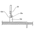
上記把持用タブ10dは、図3に示すように、オプション回路が必要となる場合、該オプション回路の端子20のタブ20aを溝10d−1に圧入させることで、電気接続用のタブとして利用することができる。
【0015】
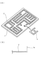
図4は第2実施形態を示す。第2実施形態の後入れバスバー10’には、その水平板部10a’の両端に上向きのタブ10b’と下向きのタブ10c’が設けられている。該後入れバスバー10’には、下向きのタブ10c’に近接した位置に上向きの把持用タブ10d’を設けている。
【0016】
上記後入れバスバー10’を絶縁板上に載置する時、把持用タブ10d’を把持すると、下向きタブ10c’を絶縁板の端子穴に挿入しやすくなる。其の際、上下にバランスが取れて、タブ10c’の端子穴挿入を精度良く行うことができる。
【0017】
【発明の効果】
以上の説明より明らかなように、本発明によれば、後入れバスバーに把持用タブを設けたため、絶縁板上の所要位置に後入れバスバーを容易に載置することができ、作業性を高めることができる。
また、上記把持用タブはオプション時に電気接続用のタブとしても利用することができ、実用的価値の大なるものである。
【図面の簡単な説明】
【図1】本発明の第1実施形態の後入れバスバーを示す斜視図である。
【図2】(A)(B)は上記後入れバスバーを絶縁板上に載置する状態を示す概略図である。
【図3】上記後入れバスバーに設けた把持用タブにオプション回路の端子を接続している状態を示す概略図である。
【図4】第2実施形態の後入れバスバーの斜視図である。
【図5】(A)(B)はバスバーの作成工程を示す概略図である。
【図6】バスバーを絶縁板に取り付ける状態を示す概略図である。
【図7】(A)(B)は従来の後入れバスバーを示す斜視図である。
【符号の説明】
10 後入れバスバー
10a 水平板部
10b、10c 電気接続用のタブ
10d 把持用タブ
10d−1 溝
20 オプション用の端子[0001]
TECHNICAL FIELD OF THE INVENTION
The present invention relates to a method of fixing a bus bar to an insulating plate, which is housed inside an electric junction box, and particularly to a bus bar fixed to the insulating plate in a last-in order to improve the workability of inserting the bus bar. It is.
[0002]
[Prior art]
As shown in FIG. 5A, this type of bus bar is formed by punching a flat
[0003]
If the number of bus bars arranged on one insulating plate is increased in order to reduce the number of stacked layers, a circuit that cannot be punched out due to interference when the tabs of the bus bar are expanded is generated. Therefore, as shown in FIG. 5A, the
[0004]
[Problems to be solved by the invention]
As shown in FIG. 7 (A), when the
Similarly, as shown in FIG. 7 (B), even if there is an
[0005]
The present invention has been made in view of the above problems, and has as its object to improve the workability of attaching a post-insert bus bar to an insulating plate.
[0006]
In order to solve the above problems, the present invention is to punch a single plate-shaped conductive plate along a circuit shape through a continuous portion divided by post-processing, and then to bend a required end portion Providing a bus bar having a tab, automatically placing the bus bar on one insulating plate, inserting the tab into a terminal hole of the insulating plate, and then caulking and fixing the insulating plate and the bus bar. At the same time, while dividing at the above continuous part for each circuit,
The after placed busbars that will be secured to the same of the insulation plate and the bus bar is provided, which protrude upward grip tab at an intermediate position of the bus bar to form a tab by bending both ends of the bus bar, An operator grips the gripping tab, inserts the tab of the post-inserted bus bar into the terminal hole of the insulating plate , and provides a method of fixing the bus bar to the insulating plate placed on the insulating plate. .
[0007]
In the post-insertion bus bar provided with the grip tabs, all the electrical connection tabs formed in the post-insertion bus bar are projected downward in the opposite direction to the grip tabs. Alternatively, in the case where the tab for the vertical electrical connection is provided but the upward electrical connection tab is not provided in the vicinity of the downward electrical connection tab, the upward grip is provided in the vicinity of the downward tab. Tabs are provided.
[0008]
When the gripping tab is provided as described above, the operator can hold the gripping tab and place the post-insert bus bar on the insulating plate. The connection tab can be easily inserted into the terminal hole of the insulating plate, and workability can be improved.
[0009]
Further, the gripping tab can also be used as an optional electrical connection tab.
[0010]
Further, the gripping tab may have a shape in which a groove for pressure contact is provided from the tip. With this configuration, it is possible to easily press-connect to a tab or a wire of a terminal of the optional circuit.
[0011]
BEST MODE FOR CARRYING OUT THE INVENTION
Hereinafter, the present invention will be described with reference to the drawings.
FIG. 1 shows a
[0012]
An upward gripping
[0013]
As shown in FIG. 2 (A), the
[0014]
As shown in FIG. 3, when an optional circuit is required, the
[0015]
FIG. 4 shows a second embodiment. The rearward insertion bus bar 10 'of the second embodiment is provided with an
[0016]
When the post-insertion bus bar 10 'is placed on the insulating plate, if the
[0017]
【The invention's effect】
As is clear from the above description, according to the present invention, since the gripping tab is provided on the post-insert bus bar, the post-insert bus bar can be easily placed at a required position on the insulating plate, and the workability is improved. be able to.
Further, the gripping tab can also be used as an electrical connection tab at the time of option, and is of great practical value.
[Brief description of the drawings]
FIG. 1 is a perspective view showing a rear insertion bus bar according to a first embodiment of the present invention.
FIGS. 2A and 2B are schematic diagrams showing a state in which the post-insert bus bar is placed on an insulating plate.
FIG. 3 is a schematic diagram showing a state in which a terminal of an optional circuit is connected to a grip tab provided on the post-insertion bus bar.
FIG. 4 is a perspective view of a post-insertion bus bar according to the second embodiment.
FIGS. 5A and 5B are schematic diagrams showing a bus bar forming process.
FIG. 6 is a schematic view showing a state where a bus bar is attached to an insulating plate.
FIGS. 7A and 7B are perspective views showing a conventional post-insertion busbar.
[Explanation of symbols]
DESCRIPTION OF
Claims (2)
上記バスバーと同一の上記絶縁板に固定される後入れバスバーを設け、該バスバーの両端を折り曲げ加工してタブを形成すると共に該バスバーの中間位置に上向きの把持用タブを突設しており、該把持用タブを作業員が把持して、該後入れバスバーのタブを上記絶縁板の端子孔に挿入して絶縁板に載置している絶縁板へのバスバーの固定方法。A single plate-shaped conductive plate is punched along a circuit shape through a continuous portion cut by post-processing, and then a required end portion is bent to provide a bus bar having a tab, and the bus bar is automatically After being placed on a single insulating plate and inserting the tab into the terminal hole of the insulating plate, the insulating plate and the bus bar are crimped and fixed, and at the same time, divided at the continuous portion for each circuit. ,
The after placed busbars that will be secured to the same of the insulation plate and the bus bar is provided, which protrude upward grip tab at an intermediate position of the bus bar to form a tab by bending both ends of the bus bar, A method of fixing the bus bar to an insulating plate placed on the insulating plate by gripping the holding tab by an operator, inserting the tab of the post-inserted bus bar into the terminal hole of the insulating plate, and mounting the bus bar to the insulating plate.
Priority Applications (1)
| Application Number | Priority Date | Filing Date | Title |
|---|---|---|---|
| JP2000160981A JP3578053B2 (en) | 2000-05-30 | 2000-05-30 | How to fix busbar to insulating plate |
Applications Claiming Priority (1)
| Application Number | Priority Date | Filing Date | Title |
|---|---|---|---|
| JP2000160981A JP3578053B2 (en) | 2000-05-30 | 2000-05-30 | How to fix busbar to insulating plate |
Publications (2)
| Publication Number | Publication Date |
|---|---|
| JP2001339825A JP2001339825A (en) | 2001-12-07 |
| JP3578053B2 true JP3578053B2 (en) | 2004-10-20 |
Family
ID=18665095
Family Applications (1)
| Application Number | Title | Priority Date | Filing Date |
|---|---|---|---|
| JP2000160981A Expired - Fee Related JP3578053B2 (en) | 2000-05-30 | 2000-05-30 | How to fix busbar to insulating plate |
Country Status (1)
| Country | Link |
|---|---|
| JP (1) | JP3578053B2 (en) |
Families Citing this family (2)
| Publication number | Priority date | Publication date | Assignee | Title |
|---|---|---|---|---|
| JP4276526B2 (en) | 2003-11-26 | 2009-06-10 | 矢崎総業株式会社 | Busbar molded body used as a component part of an electronic unit for controlling an electric junction box and an auxiliary machine of an automobile, a manufacturing method thereof, and an electronic unit |
| JP6106051B2 (en) * | 2013-08-30 | 2017-03-29 | 日立オートモティブシステムズ株式会社 | Electrical connection parts |
-
2000
- 2000-05-30 JP JP2000160981A patent/JP3578053B2/en not_active Expired - Fee Related
Also Published As
| Publication number | Publication date |
|---|---|
| JP2001339825A (en) | 2001-12-07 |
Similar Documents
| Publication | Publication Date | Title |
|---|---|---|
| US3979615A (en) | Field assembly for electric motors | |
| JPS6013268B2 (en) | electrical connectors | |
| GB1563340A (en) | Wire scribed electrical interconnecting memmer | |
| JP4886677B2 (en) | Coil with contact sleeve for electrical connection | |
| JP2655073B2 (en) | Electrical connector | |
| JPH09180797A (en) | Flat cable connection terminal | |
| JP3457239B2 (en) | Circuit forming method and circuit connection structure in electrical junction box | |
| CN107534226A (en) | Insulation displacement connector | |
| US20160374201A1 (en) | Printed circuit board with side access termination pads | |
| JP3578053B2 (en) | How to fix busbar to insulating plate | |
| US6375518B2 (en) | Connecting method of connectors | |
| JPH06260238A (en) | Connecting terminal | |
| JPS62501943A (en) | Pressure contact type electrical terminal | |
| JP3638843B2 (en) | IDC connector | |
| JPH0668321U (en) | Electrical connector terminal fittings | |
| EP1006614A2 (en) | Pressure-contact terminal and electric connection box containing pressure-contact terminals | |
| JPS63121280A (en) | Terminal application of connector | |
| JPS6227505B2 (en) | ||
| WO1999053571A1 (en) | Connecting clamp | |
| JP2008060041A (en) | Connection fixing structure of terminal | |
| JP3085446B2 (en) | Electrical junction box | |
| JP2505982B2 (en) | Method of manufacturing wiring board assembly | |
| JP3179213B2 (en) | Chain terminal | |
| JP2604523Y2 (en) | Electrical junction box | |
| JPS593482Y2 (en) | fuse boxes |
Legal Events
| Date | Code | Title | Description |
|---|---|---|---|
| A521 | Written amendment |
Free format text: JAPANESE INTERMEDIATE CODE: A523 Effective date: 20031225 |
|
| A131 | Notification of reasons for refusal |
Free format text: JAPANESE INTERMEDIATE CODE: A131 Effective date: 20040330 |
|
| A521 | Written amendment |
Free format text: JAPANESE INTERMEDIATE CODE: A523 Effective date: 20040526 |
|
| TRDD | Decision of grant or rejection written | ||
| A01 | Written decision to grant a patent or to grant a registration (utility model) |
Free format text: JAPANESE INTERMEDIATE CODE: A01 Effective date: 20040622 |
|
| A61 | First payment of annual fees (during grant procedure) |
Free format text: JAPANESE INTERMEDIATE CODE: A61 Effective date: 20040705 |
|
| R150 | Certificate of patent (=grant) or registration of utility model |
Free format text: JAPANESE INTERMEDIATE CODE: R150 |
|
| FPAY | Renewal fee payment (prs date is renewal date of database) |
Free format text: PAYMENT UNTIL: 20080723 Year of fee payment: 4 |
|
| FPAY | Renewal fee payment (prs date is renewal date of database) |
Free format text: PAYMENT UNTIL: 20090723 Year of fee payment: 5 |
|
| FPAY | Renewal fee payment (prs date is renewal date of database) |
Free format text: PAYMENT UNTIL: 20100723 Year of fee payment: 6 |
|
| FPAY | Renewal fee payment (prs date is renewal date of database) |
Free format text: PAYMENT UNTIL: 20110723 Year of fee payment: 7 |
|
| FPAY | Renewal fee payment (prs date is renewal date of database) |
Free format text: PAYMENT UNTIL: 20110723 Year of fee payment: 7 |
|
| FPAY | Renewal fee payment (prs date is renewal date of database) |
Free format text: PAYMENT UNTIL: 20120723 Year of fee payment: 8 |
|
| FPAY | Renewal fee payment (prs date is renewal date of database) |
Free format text: PAYMENT UNTIL: 20120723 Year of fee payment: 8 |
|
| FPAY | Renewal fee payment (prs date is renewal date of database) |
Free format text: PAYMENT UNTIL: 20130723 Year of fee payment: 9 |
|
| LAPS | Cancellation because of no payment of annual fees |