JP3577103B2 - Dual memory buffer apparatus and method for obtaining multiple data streams from stored data - Google Patents
Dual memory buffer apparatus and method for obtaining multiple data streams from stored data Download PDFInfo
- Publication number
- JP3577103B2 JP3577103B2 JP10594194A JP10594194A JP3577103B2 JP 3577103 B2 JP3577103 B2 JP 3577103B2 JP 10594194 A JP10594194 A JP 10594194A JP 10594194 A JP10594194 A JP 10594194A JP 3577103 B2 JP3577103 B2 JP 3577103B2
- Authority
- JP
- Japan
- Prior art keywords
- pixels
- data
- memory bank
- output
- pixel
- Prior art date
- Legal status (The legal status is an assumption and is not a legal conclusion. Google has not performed a legal analysis and makes no representation as to the accuracy of the status listed.)
- Expired - Lifetime
Links
Images


Classifications
-
- H—ELECTRICITY
- H04—ELECTRIC COMMUNICATION TECHNIQUE
- H04N—PICTORIAL COMMUNICATION, e.g. TELEVISION
- H04N5/00—Details of television systems
- H04N5/76—Television signal recording
- H04N5/907—Television signal recording using static stores, e.g. storage tubes or semiconductor memories
-
- H—ELECTRICITY
- H04—ELECTRIC COMMUNICATION TECHNIQUE
- H04N—PICTORIAL COMMUNICATION, e.g. TELEVISION
- H04N19/00—Methods or arrangements for coding, decoding, compressing or decompressing digital video signals
- H04N19/60—Methods or arrangements for coding, decoding, compressing or decompressing digital video signals using transform coding
- H04N19/61—Methods or arrangements for coding, decoding, compressing or decompressing digital video signals using transform coding in combination with predictive coding
-
- H—ELECTRICITY
- H04—ELECTRIC COMMUNICATION TECHNIQUE
- H04N—PICTORIAL COMMUNICATION, e.g. TELEVISION
- H04N19/00—Methods or arrangements for coding, decoding, compressing or decompressing digital video signals
- H04N19/85—Methods or arrangements for coding, decoding, compressing or decompressing digital video signals using pre-processing or post-processing specially adapted for video compression
Abstract
Description
【0001】
【産業上の利用分野】
本発明は、ディジタルデータの通信に関し、さらに詳しくは、ディジタル情報の連続フレームを処理して各フレームから多数の異なるデータストリームを得ることに関する。本発明は特に、異なる処理機能のために多数の異なる走査フォーマットを必要とするディジタル映像信号の通信に適用可能である。
【0002】
【従来の技術】
テレビジョン信号は従来、特定の国々で採用されている様々な標準に従って、アナログ形式で伝送されている。例えば、米国は米国テレビジョン方式委員会(NTSC)の標準を採用している。欧州の大半の国々は、PAL(Phase Alternating Line)またはSECAM(Sequential Color And Memory)標準を採用している。
【0003】
テレビジョン信号のディジタル伝送は、アナログ技術よりずっと高い品質の映像および音声サービスを配布することができる。ディジタル伝送方式は、衛星によってケーブルテレビ加入者へ、および/または直接に家庭用衛星テレビ受信機へ放送される信号にとって特に有利である。ディジタルテレビジョン送受信システムは、オーディオ業界でディジタルコンパクトディスクがアナログ蓄音機レコードに大部分取って代わったのとちょうど同じように、既存のアナログシステムに取って代わるであろうと予想される。
【0004】
ディジタルテレビジョンシステムでは、かなりの量のディジタルデータを伝送しなければならない。高精細度テレビジョン(HDTV)の場合には特にそうである。ディジタルテレビジョンシステムでは、加入者は、映像、音声、およびデータを加入者に提供する受信機/デスクランブラを介して、ディジタルデータストリームを受信する。利用可能な無線周波数スペクトルを最も効率的に使用するために、ディジタルテレビジョン信号を圧縮し、伝送しなければならないデータの量を最小にすることが有利である。
【0005】
テレビジョン信号の映像部は、ひとつにまとまって動画を形成する一続きのビデオフレームから成る。ディジタルテレビジョンシステムでは、ビデオフレームの各走査線は、「画素」と呼ばれる一続きのディジタルデータによって形成される。テレビジョン信号の各ビデオフレームを形成するためには、大量のデータが必要である。例えば、NTSC解像度で1ビデオフレームを形成するには、7.4メガビットのデータが必要になる。これは、640画素×480走査線の画面を使用し、赤、緑および青の三原色のそれぞれに8ビットの輝度値を使用する場合を想定したものである。高精細度テレビジョンの場合には、それよりかなり多くのデータが、各ビデオフレームを形成するために必要である。この量のデータを扱うためには、特にHDTVの場合には、データを圧縮しなければならない。ビデオ圧縮技術は、従来の通信チャネルによるディジタル映像信号の効率的な伝送を可能にする。こうした技術は、映像信号の重要な情報をより効率的に表現するために、隣接画素間の相関を利用する圧縮アルゴリズムを使用する。
【0006】
最も効果的で頻繁に使用される分類に属するビデオ圧縮のアルゴリズムの1つは、「変換符号化(transform coder)」と呼ばれている。このようなシステムでは、画像のブロックが線形的および連続的に、画像強度ドメインとは大きく異なる特徴を持つ新しいドメインに変換される。ブロックは、離散コサイン変換の(DCT)の場合のように重ならないときもあり、ラップト直交変換(lapped orthogonal transform)(LOT)の場合のように重なるときもある。DCTを使用したシステムは、チェンおよびプラット著”Scene Adaptive Coder”, IEEE Transactions on Communications, Vol. COM−32, No. 3, March 1984および1988年12月13日にリューらに発行された”Two−Dimensional Discrete Cosine Transform Processor”と題する米国特許第4,791,598号に記述されている。LOTを使用したシステムは、マルバーおよびステーリン著”The LOT: Transform Coding Without Blocking Effects”, IEEE Transactions on Acoustics, Speech, and Signal Processing, Vol. 37, No. 3, April 1989に記述されている。
【0007】
画像変換は、画像強度の画素間に存在する相関を減少するために使用される。こうして、これらの変換はエネルギを比較的少数の変換係数に凝集する。多くの一般的な変換は、人間の視覚系のモデルに基づく係数の量子化を容易にする性質を持つ。例えば、DCTは、周波数スペクトルの特定の帯域のエネルギを表わす振幅を持つ係数を生成する。したがって、人の視覚器が画像の高周波領域または細部領域より低周波領域の誤差に敏感であるという事実を利用することができる。一般に、高周波係数は常に低周波より粗に量子化される。
【0008】
DCTの出力は、エネルギを2次元周波数ドメインで表わす係数のマトリックスである。エネルギの多くは、低周波領域であるマトリックスの左上角に集中する。係数を左上角からジグザクに走査すると、得られるシーケンスは、特にシーケンスの終りの方に長いゼロの列を含むことになる。DCT圧縮アルゴリズムの主要な目的の1つは、ゼロを生成し、これらを一つに束ねて効率的な符号化を達成することである。
【0009】
送信された係数のストリームから映像信号を再構築するためには、信号を符号化するために用いた変換(例えばDCT)の逆を行う必要がある。一般に、変換係数は8×8ブロックまたは16×16ブロックのように、n×nブロックの係数を単位として伝送される。係数を逆変換するためには、送信機で使用したのと同じブロック・フォーマット走査順序(例えばジグザグ走査)を使用して、受信機でこれらを再順序付けする必要がある。
【0010】
また、例えば、DCT処理で使用するブロック走査ではなく、線単位(line−by−line)走査が必要な「フィルム・モード」による処理を可能にする場合など、入力した画素を異なる順序で並べる方が望ましいこともある。
【0011】
入力ディジタル画像データのフレームを処理する前に保存するために、2つのメモリバッファを使用することは周知である。一般に、現在のフレームの入力画像データが第1メモリバンクに保存され、その間に前のフレームのデータが第2メモリバンクから読み出される。1つのフレームが終るとバッファが交換され、1フレームのデータを受け取ったばかりのメモリバンクはそのデータを出力し、もう1つのメモリバンクは次のフレームのデータを受け取る。この技術は、入力画像データの走査フォーマットを、その後の処理に必要なフォーマットに変換するのに便利である。
【0012】
【発明が解決しようとする課題】
異なる処理機能のために2つの異なる走査フォーマットが必要な場合、追加メモリバンクが設けられてきた。追加メモリバンクを設けると、システム設計が複雑かつ高価になる程度にまで、メモリおよびそれに伴うハードウェアの要件が増加する。
【0013】
2つだけのメモリバンクを利用して、異なる走査フォーマットを必要とする多数の異なる処理機能をサポートする機構を提供することは利益になる。そうした機構は、システムのスループットを低下することなく、同一の受信情報に基づいて多数の異なる出力データストリームを形成しなければならない。
【0014】
本発明は、上述の利点を備えた、複数データストリームを出力するためのデュアルメモリバッファ機構を提供する。
【0015】
【課題を解決するための手段】
本発明に従って、ディジタル情報バイトを含む連続フレームを保存し、その後に各フレームについてN個のデータストリームを出力する装置を提供する。前記バイトは、用途によって任意の長さとすることができる(例:8ビット)。N個のデータストリームのそれぞれが、その後の処理のために異なる順序でそのフレームに対するバイトを提供する。例えば、フレームが画像データ(つまり画素)のフレームである場合、1つのデータストリームではブロックフォーマットによるDCT処理のために画素を提供し、別のデータストリームでは線単位によるフィルムモード処理のために画素を提供することができる。
【0016】
この装置は、交互フレームを保存する第1および第2メモリバンクから成る。第1メモリバンクは入力フレームのバイトを保存するように適応され、その間に第2メモリバンクは前のフレームのバイトを出力する。その次のフレームでは第1メモリバンクと第2メモリバンクの役割が逆になり、これが交互に繰り返される。第1および第2メモリバンクにおけるバイトの入力および出力を制御する手段を設ける。メモリバンクは、この制御手段によって提供される読出しおよび書込みストローブおよびアドレスに応答し、(i)1回の書込みストローブに対しNバイトの率で、書込みアドレスによって決定される順序で入力フレームデータを保存し、(ii)1回の読出しストローブで、N個の異なるデータストリームのうちの次の連続データストリームに対し、読出しアドレスによって指定されたNバイトのフレームデータを出力する。N回の読出しストローブごとに1回の書込みストリームが発生する。1回の読出しストローブごとに各データストリームに1バイトを提供するために、N個の異なるデータストリームのそれぞれに対しメモリバンクから出力されるフレームデータをバッファリングする手段を設ける。
【0017】
制御手段は、各メモリバンク用の書込みアドレス生成器およびN読出しアドレス生成器から構成することができる。メモリバンクが入力フレームからバイトを保存するために受け取ったときに、1つのメモリバンクの書込みアドレス生成器をそのメモリバンクのアドレスポートに結合する手段を設ける。また、メモリバンクがそこからバイトを出力するときに、そのメモリバンクの異なる読出しアドレス生成器をメモリバンクのアドレスポートに連続的に結合する手段を設ける。さらに、一度に1つのフレームのデータを処理するために、第1および第2メモリバンクをバッファリング手段に交互に結合する手段を設けることができる。
【0018】
バッファリング手段は、現在の読出しアドレスに応答してメモリバンクによって出力されるN個のデータバイトを一度に受け取るために、制御手段によって生成されるそれぞれのイネーブル信号に応答するN個のレジスタから構成することができる。各レジスタに対応するデータセレクタが、連続読出しストローブに応答して、レジスタからNデータバイトのそれぞれを連続的に出力する。各データセレクタは、データセレクタに対応するレジスタが使用許可(イネーブル)されたときに、現在の読出しアドレスによって指定された順序でデータバイトの連続ストリームを出力する。
【0019】
別の実施例では、バッファリング手段は、それぞれのメモリバンクに対し、各メモリバンクに結合されたN個のレジスタから構成することができる。各レジスタは制御手段によって生成されるそれぞれのイネーブル信号に応答し、現在の読出しアドレスに応答してメモリバンクから出力されるN個のデータバイトを一度に受信する。各レジスタに対応するデータセレクタは、連続読出しストローブに応答して、レジスタからNデータバイトのそれぞれを連続的に出力する。また、第1および第2メモリバンクのそれぞれに対応するデータセレクタから出力されるデータバイトを多重化する手段を設ける。この多重化手段は、N個の連続ストリームのデータバイトを出力する。各ストリームは、ストリームを形成するために用いられるデータセレクタに対応するレジスタが使用許可されたときに、現在の読出しアドレスによって指定される順序でデータバイトを提供する。
【0020】
本発明に係る方法では、画素データの連続フレームを処理して、画素データを様々な順序で含むN個のデータストリームを形成する。入ってきたフレームの画素データは、1書込みサイクルにつきN個の画素の率で第1メモリバンクに保存され、前のフレームの画素データは1回の読出しサイクルにつきN個の画素の率で第2メモリバンクから出力され、これが第1および第2メモリバンクの間で交互に繰り返される。読出しサイクルは書込みサイクルのN倍の率であり、1書込みサイクルにつきN個の画素を1組としてN組の出力画素が得られる。N組のそれぞれに対しメモリバンクから出力される画素はバッファリングされ、N個のデータストリームを形成する。各読出しサイクル中に、画素データを出力するメモリバンクは新しくアドレス指定され、データストリームのうちの次の連続ストリームのためにN個1組の画素を出力する。
【0021】
さらに、本発明に従って、連続フレームの画素データを処理し、画素データを異なる順序で含む2つのデータストリームを形成する装置を提供する。また、現在の入力ビデオフレームからの画素をグループ化し、第1クロックレートφで第1メモリバンクに保存するために、画素の連続対を提供する手段を設ける。また、現在のビデオフレームからの画素の対をレートφで第1メモリバンクに保存している間に、前のビデオフレームの保存された画素の対を第2メモリバンクから第2クロックレート2φで読み出す手段を設ける。この読出し手段は、現在のビデオフレームから保存される各対の画素に対し、前のビデオフレームから2対の画素を読み出す。さらに、読出し手段によって得られる画素の対を2つのデータストリームに結合する手段を設ける。各データストリームは、前のフレームからの画素を異なる順序で提供する。
【0022】
画素をグループ化する手段は、入力ビデオフレームから1クロックサイクルだけ画素を遅延させるラッチから構成することができる。ラッチからの遅延画素を入力ビデオフレームにおける次の連続画素と結合して、1対の画素を提供する手段も設ける。
【0023】
読出し手段によって得た画素の対を2つのデータストリームに結合する手段は、第1および第2出力レジスタから構成することができる。読出し手段によって得た画素の対を1つおきに第1出力レジスタに入力し、読出し手段によって得た画素の対の残りを第2出力レジスタに入力する手段を設ける。さらに、第1出力レジスタから一度に1つづつ画素を検索して、2つのデータストリームのうちの1つを提供する手段を設ける。また、第2出力レジスタから一度に1つづつ画素を検索して、もう一方のデータストリームを形成する手段を設ける。
【0024】
読出し手段は、第2メモリバンクに第2クロックレート2φで別個のアドレスを提供するために結合されたアドレス生成器から構成することができ、これによって、現在のビデオフレームから保存される各対の画素に対し、前のビデオフレームから2対の画素が読み出される。一方のメモリバンクが画素を保存するために受け取る間に、他方のメモリバンクが画素を出力するように、第1および第2メモリバンクを交互に結合するため、スイッチ手段を設けることができる。
【0025】
別の実施例では、読出し手段によって得た画素の対を2つのデータストリームに結合する手段が、それぞれのメモリバンクに対応する別個のレジスタから成る。第1メモリバンクから画素を受け取るために、第1および第2出力レジスタを結合する。第1メモリバンクから出力される画素の対を1つおきに第1出力レジスタに入力し、第1メモリバンクから出力される残りの画素の対を第2出力レジスタに入力するための手段を設ける。さらに、第2メモリバンクから画素を受け取るために、第3および第4出力レジスタを結合する。第2メモリバンクから出力された画素の対を1つおきに第3出力レジスタに入力し、第2メモリバンクから出力される残りの画素の対を第4出力レジスタに入力するための手段を設ける。さらに、第1および第3出力レジスタから一度に1つづつ画素を検索し、2つのデータストリームのうちの1つを形成する手段を設ける。画素は第2および第4出力レジスタから一度に1つづつ検索され、もう一方のデータストリームりーむを形成する。
【0026】
【実施例】
本発明は、2つのメモリバンクおよび関連出力バッファを使用することにより、連続フレームのディジタル情報を記憶し、このディジタル情報を異なる順序で含む複数のデータストリームを出力することを可能にする。本発明を実現する装置の第1実施例を、図1に示す。入力データは、説明の目的のために連続ディジタルビデオフレームの画素によって構成することができるが、これはデータ入力端子10を介してラッチ12に結合される。ラッチ12は2φのクロックレートで刻時される。これはデータが第1および第2メモリバンクにそれぞれ書き込まれるレートの2倍である。図に示す実施例の場合、各画素の長さは8ビットである。ラッチ12の出力位置で、端子10からの現在の8ビット画素が、ラッチ12によって遅延された前の8ビット画素と結合され、書込みサイクル中に第1メモリバンク16または第2メモリバンク18のどちらかに一緒に入力される1対の画素(合計16ビット)を形成する。
【0027】
現在のフレームからの画素は全てメモリバンクの一方に書き込まれ、その間に前のフレームからの画素は他方のメモリバンクから読み出される。入力データの新しいフレームが始まるたびにメモリバンクが交換されるので、どの瞬間においてもシステムは一方のメモリバンクに書込みを行い、その間に他方のメモリバンクから読出しを行う。データが書き込まれるメモリバンクは、図2に示すシステム制御プロセッサ60から「次のフレーム」信号を受信するたびにトグルするスイッチ14によって制御される。制御プロセッサは、受信した画素数(バイト)の計数を維持することによって、それぞれの新しいフレームを識別することができる。
【0028】
図に示す実施例では、各フレームの入力データに対し2つのデータストリームが形成される。しかし、当業者は、各記憶場所に書き込まれるバイト数を増加し、かつメモリからのデータ読出しレートをメモリへのデータ書込みレートに対しN倍に高めるだけで、任意の数N個のデータストリームを形成することが可能であることを理解されるであろう。図に示す実施例では、画素レート2φ(これは「読出しストローブ」レートでもある)の半分にあたるφのレートで書込みストローブに応答して2つの画素を各記憶場所に書き込むことによって、2つのデータストリームの出力を達成する。こうして、先に述べたように、スイッチ14の入力位置で、書込みストローブごとに適切なメモリバンクに記憶するための2つの連続画素を同時に得ることができる。
【0029】
出力における2つの異なる走査フォーマットをサポートするために、データストリームフォーマットごとに別個の読出しアドレス生成器が必要である。別個のアドレスは、第1メモリバンク16のアドレスポートADD 1および第2メモリバンク18のアドレスポートADD 2を介して、制御プロセッサ60によってメモリバンクに提供される。
【0030】
図3は、制御プロセッサ60による異なるアドレスの生成を示す。制御プロセッサ60は特に、両方のメモリバンク16、18用の第1読出しアドレス生成器70、第2アドレス生成器72、および書込みアドレス生成器74を備えている。マルチプレクサまたはスイッチ76は、アドレス生成器70、アドレス生成器72、またはアドレス生成器74の出力の1つを、第1メモリバンク16のまたは第2メモリバンク18のそれぞれのアドレスポートADD 1またはADD 2への入力として選択する。書込みアドレス生成器は、メモリバンクに書き込まれる全てのデータの書込みアドレスを提供するために使用される。第1読出しアドレス生成器70は、第1出力データストリーム(データストリーム1)を形成するために必要な順序でデータをメモリバンクから読み出すために使用される。第2読出しアドレス生成器72は、第2出力データストリーム(データストリーム2)に必要な順序でデータをメモリバンクから読み出すために必要なアドレスを提供するために使用される。読出しストローブは書込みストローブの2倍のレートであるので、データを出力するメモリバンクは、書込みストローブに対応して現在データを保存中のメモリに1組のデータが入力されるたびに、異なる2組のデータを出力するようにアドレス指定することができる。
【0031】
出力メモリバンクから出力される2組のデータを組み合わせて所望の2つの異なる出力データストリームを形成するためには、追加ハードウェアが必要である。このハードウェアはスイッチ14に相応するスイッチ20であり、第1および第2メモリバンクのどちらが前に保存されたフレームのデータを出力し、どちらが現在のフレームからデータを受信するかを選択する。全体的に符号21で示すバッファリング回路は、出力データを組み合わせて2つの別個のデータストリームを形成するために設けられている。
【0032】
図1の実施例におけるバッファ回路機構21は、データストリーム1に対応する第1レジスタ22およびデータストリーム2に対応する第2レジスタ24を備えている。出力メモリバンクに提供されるアドレスに応答して、読出しストローブごとに出力される16ビット対の画素は、レジスタ22およびレジスタ24の両方に入力される。しかし、レジスタ22、24はイネーブルされたときに1対の画素をラッチするだけである。レジスタ22は、制御プロセッサ60から出力されるENA A信号に応答して第1画素対をラッチし、レジスタ24は制御プロセッサ60から出力されたENA B信号に応答して第2画素対をラッチする。第1および第2画素対は、単一書込みストローブに対応する2つの連続読出しストローブ中に出力される。レジスタ22は、読出しストローブ中に出力メモリバンクから受け取った16ビットを、その2つの8ビット画素に分割する。データセレクタ26は、個々の画素を直列化してデータストリーム1を形成するために、レジスタ22の2つの8ビット出力の間の切換えを行う。データストリーム1は端子27から出力される。同様に、レジスタ24は、イネーブルされたときにラッチした16ビット対の画素を2つの別個の8ビット画素成分に分割する。データセレクタ28は、個々の画素を組み合わせてデータストリーム2を形成するために、レジスタ24の2つの8ビット出力の間の切換えを行う。データストリーム2は端子29から出力される。
【0033】
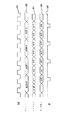
図1の装置の動作は、図4および図5のタイミング図を参照することによって、よりよく理解することができる。図4は、スイッチ14を介してデータを現在受け取る側のメモリバンク16または18にデータを書き込むために使用されるタイミングを示す。書込みストローブ88は、システムクロック80の半分のレートで提供される。システムクロック80は2φのレートで作動する。これは読出しストローブのレートと同じである。ラッチ12の出力に現れる2つの画素の宛先として受取側メモリバンクの次の記憶場所を指定するために、各書込みサイクル中に書込みアドレス82のストリームから個別書込みアドレスが得られる。ストリーム84、86は、各書込みサイクル中に2つの画素がそれぞれの記憶場所に書き込まれることを示す。例えば、第1書込みサイクル中に画素α0およびα1がアドレスADR0によって指定される記憶場所に入力される。次の書込みサイクル中には、画素α2およびα3がADR1によって指定された記憶場所に保存される。次の書込みサイクル中には、画素α4およびα5がADR2によって指定された記憶場所に保存される。ストリーム84は端子10に入力されるデータであり、ストリーム86はラッチ12によって1クロックサイクル遅延させたデータである。図4から、各書込みストローブ88中に、現在のアドレス82によって指定された記憶場所に書き込むために、2つの画素が得られることが明らかである。
【0034】
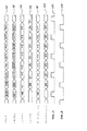
メモリバンクの一方に1フレームのデータが保存された後、そのデータがメモリバンクから読み出され、その間に次のフレームのデータがもう一方のメモリバンクに書き込まれるように、スイッチ14、20はトグル動作を行う。読出し動作中は、メモリ書込み動作中のように2クロックサイクル80ごとに1つのアドレス82が提供されるのではなく、図5に符号90で示すように、各クロックサイクルごとに個別アドレスが提供される。図に示す例では、第1データストリームはDCT処理に必要な順序でデータを提供し、第2データストリームはフィルム処理モード(FM)に従って処理するためのデータを提供する。これを達成するために、1つおきのアドレス90で、DCT処理またはフィルムモード処理のどちらかのために順序付けたデータを交互に提供する。こうして、例えば、図5の符号90、92で示すように、読出しアドレスDCT0に応答して、現在データを出力している側のメモリが画素α0、α1を出力する。次の読出しストローブでは、読出しアドレスFM0が、現在データを出力している側のメモリバンクをアドレス指定する。アドレスFM0に応答して、このメモリバンクは現在保存されているビデオフレームの画素β0、β1を出力する。次の読出しストローブでは、アドレスDCT1がメモリバンクに提供され、メモリバンクは画素α2、α3を出力することによって応答する。次の読出しストローブでは、アドレスFM1がメモリバンクに提供され、メモリバンクはこれに応答してβ2、β3を出力する。このプロセスが続き、1つおきの読出しストローブごとにDCT画素対またはフィルムモード画素対がメモリバンクから出力される。
【0035】
レジスタ22はENA A信号によってイネーブルされ、DCTアドレスに応答して出力されるDCT順序の画素だけをラッチする。これを符号94で示す。同様に、レジスタ24はENA B信号に応答し、フィルムモードアドレスに応答してフィルムモード順序でメモリバンクから出力される画素だけをラッチする。これを図5の符号96で示す。ENA A信号およびENA B信号はそれぞれ図5の符号102、104で示す。
【0036】
レジスタ22はDCT処理用に出力される順序の画素だけを保存するので、データセレクタ26を読出しストローブレート2φでトグルすることにより、符号98で示すように連続画素α0、α1、α2、α3・・・を含むデータストリーム1が出力端子27から得られる。同様に、データセレクタ28は、符号100で示すようにβ0、β1、β2、β3、β4・・・の順序の画素から成るデータストリーム2を端子29から出力する。
【0037】
各アドレス位置に2つの画素が書き込まれるので、メモリバンクのアドレス指定が読出しストローブレートの2分の1の書込みストローブレートで行われても、システムのスループットは低下しない。実際、各アドレス位置に2つの画素を書き込むことによって、本発明は2つの異なるストリームにデータを読み出す能力を提供する。各ストリームにおけるデータの順序は、図3に示す第1読出しアドレス生成器70および第2読出しアドレス生成器72によって出力側メモリバンクに提供されるアドレスによってのみ制御される。これらの読出しアドレス生成器は、図5に示すアドレスストリーム90を提供する。
【0038】
図6は本発明の別の実施例を示す。この例では、第1および第2メモリバンク16、18のそれぞれに別個のレジスタを設ける。こうして、データを出力側メモリから共通バッファリング回路機構21へ送り出すためのスイッチ20を設ける代わりに、図6の実施例では、第1メモリバンク16にレジスタ30、32を対応させ、第2メモリバンクにレジスタ34、36を対応させる。レジスタ30、32、34、36の動作は、図1の実施例のレジスタ22、24の動作と同様である。各レジスタに対し、ENA AまたはENA B信号のいずれか、および2φのレートの読出しストローブが入力される。16ビット画素対を直列化して連続8ビット画素を形成するために、各レジスタにはデータセレクタ40、42、44、または46が対応付けられている。スイッチ48、50は、それぞれ制御プロセッサ60(図2)からの次のフレーム信号に応答し、現在データを出力している側のメモリバンクからそれぞれのデータストリームを出力する。特に、第1メモリバンク16がデータを出力しているとき、データストリーム1のために適切な順序に並べられた画素が、スイッチ48を介して端子52から出力される。第2メモリバンクがデータを出力しているとき、データストリーム1の順序の画素がスイッチ48を介して端子52から出力し続ける。一方、スイッチ50は、第1メモリバンク16からの画素をデータストリーム2の順序で端子54を介して出力する。第2メモリバンクがデータを出力するとき、スイッチ50は適切に順序付けられた画素を端子54に結合する。
【0039】
これで、本発明が連続フレームの画素データを処理し、画素データを異なる順序で含むN個のデータストリームを提供することが理解されるはずである。入力フレームの画素データは、書込みサイクルごとにN個の画素の率で第1メモリバンクに保存され、その間に前のフレームの画素データが、読出しサイクルごとにN個の画素の率で第2メモリバンクから出力される。読出しサイクルは書込みサイクルのN倍のレートであり、1回の書込みサイクルにつきN個の画素を1組としてN組の出力画素が得られる。N組のそれぞれに対しメモリバンクから出力された画素はバッファに入れられ、適切な順序のN個のデータストリームを形成する。
【0040】
本発明を種々の特定の実施例に関連して説明してきたが、当業者は、請求の範囲に記載する本発明の精神および範囲から逸脱することなく、多くの適応や変更を行うことができることを理解されるであろう。例えば、本発明はディジタル画像データ以外のデータの処理に適用することができる。さらに、先に述べたように、各メモリ位置に保存されるバイト数を増加し、それに対応して書込みストローブに対する読出しストローブのレートを増加することによって、任意の数のデータストリームを提供することが可能である。
【図面の簡単な説明】
【図1】各入力フレームのデータに対し2つの異なるデータストリームを出力する、本発明に係るデュアルメモリバッファ機構の第1実施例のブロック図である。
【図2】図1および図6の装置によって使用される様々な制御信号を生成するのに使用される制御プロセッサを示すブロック図である。
【図3】図2の制御プロセッサによって出力される様々な読出しおよび書込みアドレスを提供する回路機構を示すブロック図である。
【図4】本発明に係るメモリバンクにデータを書き込むために得られる様々なタイミング信号を示すタイミング図である。
【図5】本発明に係るメモリバンクからデータを読み出すために必要な様々なタイミング信号を示すタイミング図である。
【図6】第1および第2メモリバンクのそれぞれに対し別個の出力バッファを設けた、本発明の装置の別の実施例のブロック図である。
【符号の説明】
10 データ入力端子
12 ラッチ
14 スイッチ
16 第1メモリバンク
18 第2メモリバンク
21 バッファリング回路
22 第1レジスタ
24 第2レジスタ
26 データセレクタ
28 データセレクタ
60 システム制御プロセッサ
70 第1読出しアドレス生成器
72 第2読出しアドレス生成器
74 書込みアドレス生成器
76 マルチプレクサ[0001]
[Industrial applications]
The present invention relates to the communication of digital data, and more particularly to processing successive frames of digital information to obtain a number of different data streams from each frame. The invention is particularly applicable to the communication of digital video signals requiring many different scanning formats for different processing functions.
[0002]
[Prior art]
Conventionally, television signals are transmitted in analog form according to various standards adopted in certain countries. For example, the United States has adopted the standards of the National Television System Committee (NTSC). Most countries in Europe have adopted the PAL (Phase Altering Line) or SECAM (Sequential Color And Memory) standard.
[0003]
Digital transmission of television signals can deliver much higher quality video and audio services than analog technology. Digital transmission schemes are particularly advantageous for signals broadcast by satellite to cable television subscribers and / or directly to home satellite television receivers. It is anticipated that digital television transmission and reception systems will replace existing analog systems, just as digital compact discs have largely replaced analog phonograph records in the audio industry.
[0004]
In digital television systems, a significant amount of digital data must be transmitted. This is especially true in the case of high definition television (HDTV). In a digital television system, a subscriber receives a digital data stream via a receiver / descrambler that provides video, audio, and data to the subscriber. To most efficiently use the available radio frequency spectrum, it is advantageous to compress digital television signals and minimize the amount of data that must be transmitted.
[0005]
The video portion of a television signal consists of a series of video frames that together form a moving image. In digital television systems, each scan line of a video frame is formed by a series of digital data called "pixels". A large amount of data is required to form each video frame of a television signal. For example, forming one video frame at NTSC resolution requires 7.4 megabits of data. This is based on the assumption that a screen of 640 pixels × 480 scanning lines is used and an 8-bit luminance value is used for each of the three primary colors of red, green and blue. In the case of high definition television, significantly more data is needed to form each video frame. To handle this amount of data, the data must be compressed, especially in the case of HDTV. Video compression techniques allow for the efficient transmission of digital video signals over conventional communication channels. These techniques use compression algorithms that make use of the correlation between adjacent pixels to more efficiently represent important information in the video signal.
[0006]
One of the most effective and frequently used classifications of video compression algorithms is called "transform coding". In such a system, blocks of an image are linearly and continuously transformed into a new domain with features that differ significantly from the image intensity domain. The blocks may not overlap as in the case of the discrete cosine transform (DCT), or may overlap as in the case of the wrapped orthogonal transform (LOT). A system using DCT is described in Chen and Pratt, "Scene Adaptive Coder," IEEE Transactions on Communications, Vol. COM-32, no. 3, March 1984 and U.S. Pat. No. 4,791,598 entitled "Two-Dimensional Discrete Cosine Transform Processor" issued Dec. 13, 1988 to Liu et al. A system using LOT is described by Malver and Stalin in "The LOT: Transform Coding With Blocking Effects", IEEE Transactions on Acoustic's, Speech, and Signal. 37, No. 3, April 1989.
[0007]
Image transformation is used to reduce the correlation that exists between pixels of image intensity. Thus, these conversions coalesce energy into a relatively small number of conversion factors. Many common transforms have properties that facilitate quantization of coefficients based on models of the human visual system. For example, DCT generates coefficients having an amplitude that represents the energy in a particular band of the frequency spectrum. Thus, one can take advantage of the fact that human visual organs are more sensitive to errors in the low frequency region than in the high frequency or detail regions of the image. In general, high frequency coefficients are always quantized more coarsely than low frequencies.
[0008]
The output of the DCT is a matrix of coefficients representing energy in the two-dimensional frequency domain. Much of the energy is concentrated in the upper left corner of the matrix, the low frequency region. Scanning the coefficients zigzag from the upper left corner, the resulting sequence will contain a long sequence of zeros, especially towards the end of the sequence. One of the main goals of the DCT compression algorithm is to generate zeros and bundle them together to achieve efficient encoding.
[0009]
To reconstruct a video signal from a stream of transmitted coefficients, it is necessary to perform the inverse of the transform (eg, DCT) used to encode the signal. Generally, transform coefficients are transmitted in units of n × n block coefficients, such as 8 × 8 blocks or 16 × 16 blocks. Inverting the coefficients requires reordering them at the receiver using the same block format scan order used at the transmitter (eg, zigzag scan).
[0010]
A method of arranging input pixels in a different order, for example, in a case where processing in a “film mode” that requires line-by-line scanning instead of block scanning used in DCT processing is enabled. May be desirable.
[0011]
It is well known to use two memory buffers to store frames of input digital image data before processing. Generally, input image data for the current frame is stored in a first memory bank, while data for a previous frame is read from a second memory bank. At the end of one frame, the buffers are exchanged, the memory bank that has just received one frame of data outputs that data, and the other memory bank receives the next frame of data. This technique is useful for converting the scan format of the input image data into a format required for subsequent processing.
[0012]
[Problems to be solved by the invention]
If two different scan formats are needed for different processing functions, additional memory banks have been provided. The provision of additional memory banks increases the memory and associated hardware requirements to the extent that the system design is complex and expensive.
[0013]
It would be beneficial to utilize only two memory banks to provide a mechanism to support a number of different processing functions requiring different scan formats. Such a mechanism must form many different output data streams based on the same received information without degrading system throughput.
[0014]
The present invention provides a dual memory buffer mechanism for outputting multiple data streams with the advantages described above.
[0015]
[Means for Solving the Problems]
In accordance with the present invention, there is provided an apparatus for storing successive frames containing digital information bytes and thereafter outputting N data streams for each frame. The byte can be of any length depending on the application (eg, 8 bits). Each of the N data streams provides bytes for the frame in a different order for subsequent processing. For example, if the frame is a frame of image data (ie, pixels), one data stream provides pixels for DCT processing in block format, and another data stream provides pixels for film mode processing on a line-by-line basis. Can be provided.
[0016]
The device comprises first and second memory banks for storing alternating frames. The first memory bank is adapted to store the bytes of the input frame, while the second memory bank outputs the bytes of the previous frame. In the next frame, the roles of the first memory bank and the second memory bank are reversed, and this is alternately repeated. Means are provided for controlling the input and output of bytes in the first and second memory banks. The memory bank is responsive to the read and write strobes and addresses provided by the control means, and (i) stores the input frame data at a rate of N bytes per write strobe in an order determined by the write address. (Ii) With one read strobe, N-byte frame data specified by the read address is output to the next continuous data stream among the N different data streams. One write stream occurs every N read strobes. Means are provided for buffering frame data output from the memory bank for each of the N different data streams to provide one byte for each data stream for each read strobe.
[0017]
The control means may comprise a write address generator and an N read address generator for each memory bank. Means are provided for coupling a write address generator of one memory bank to an address port of the memory bank when the memory bank receives a byte from an input frame for storage. Means are also provided for sequentially coupling different read address generators of the memory bank to the address ports of the memory bank when the memory bank outputs bytes therefrom. Further, means may be provided for alternately coupling the first and second memory banks to the buffering means for processing data of one frame at a time.
[0018]
The buffering means comprises N registers responsive to respective enable signals generated by the control means for receiving at a time N data bytes output by the memory bank in response to the current read address. can do. A data selector corresponding to each register continuously outputs each of the N data bytes from the register in response to the continuous read strobe. Each data selector outputs a continuous stream of data bytes in the order specified by the current read address when the register corresponding to the data selector is enabled (enabled).
[0019]
In another embodiment, the buffering means may comprise, for each memory bank, N registers coupled to each memory bank. Each register is responsive to a respective enable signal generated by the control means and receives at a time N data bytes output from the memory bank in response to the current read address. The data selector corresponding to each register continuously outputs each of the N data bytes from the register in response to the continuous read strobe. Further, there is provided means for multiplexing data bytes output from the data selector corresponding to each of the first and second memory banks. The multiplexing means outputs data bytes of N continuous streams. Each stream provides data bytes in the order specified by the current read address when the register corresponding to the data selector used to form the stream is enabled.
[0020]
In the method according to the invention, successive frames of pixel data are processed to form N data streams containing the pixel data in various orders. The incoming frame pixel data is stored in the first memory bank at a rate of N pixels per write cycle, and the previous frame pixel data is stored at a rate of N pixels per read cycle at the second pixel rate. The data is output from the memory bank, and this is alternately repeated between the first and second memory banks. The read cycle is N times the rate of the write cycle, and N sets of output pixels are obtained with one set of N pixels per write cycle. The pixels output from the memory bank for each of the N sets are buffered to form N data streams. During each read cycle, the memory bank that outputs pixel data is newly addressed and outputs a set of N pixels for the next continuous stream of data streams.
[0021]
Further, in accordance with the present invention, there is provided an apparatus for processing pixel data of successive frames to form two data streams comprising the pixel data in different orders. Also provided is a means for providing a continuous pair of pixels for grouping the pixels from the current input video frame and storing them in the first memory bank at the first clock rate φ. Also, while storing pairs of pixels from the current video frame in the first memory bank at the rate φ, the pairs of pixels stored in the previous video frame are stored from the second memory bank at the second clock rate 2φ. A reading means is provided. The reading means reads two pairs of pixels from the previous video frame for each pair of pixels stored from the current video frame. Furthermore, means are provided for combining the pairs of pixels obtained by the reading means into two data streams. Each data stream provides pixels from a previous frame in a different order.
[0022]
The means for grouping pixels can consist of a latch that delays pixels by one clock cycle from the input video frame. Means are also provided for combining the delayed pixel from the latch with the next successive pixel in the input video frame to provide a pair of pixels.
[0023]
The means for combining the pairs of pixels obtained by the reading means into two data streams may comprise first and second output registers. Means are provided for inputting every other pair of pixels obtained by the reading means to the first output register, and inputting the rest of the pixel pairs obtained by the reading means to the second output register. Further, means are provided for retrieving pixels one at a time from the first output register to provide one of the two data streams. Means are provided for retrieving pixels one at a time from the second output register to form another data stream.
[0024]
The reading means can consist of an address generator coupled to provide a separate address at a second clock rate 2φ to the second memory bank, whereby each pair of data stored from the current video frame is stored. For a pixel, two pairs of pixels are read from the previous video frame. Switch means can be provided to alternately couple the first and second memory banks such that one memory bank receives the pixels for storage while the other memory bank outputs the pixels.
[0025]
In another embodiment, the means for combining the pairs of pixels obtained by the reading means into two data streams comprises a separate register corresponding to each memory bank. The first and second output registers are combined to receive a pixel from the first memory bank. Means are provided for inputting every other pair of pixels output from the first memory bank to the first output register, and inputting the remaining pairs of pixels output from the first memory bank to the second output register. . Further, the third and fourth output registers are combined to receive pixels from the second memory bank. Means are provided for inputting every other pair of pixels output from the second memory bank to the third output register, and inputting the remaining pairs of pixels output from the second memory bank to the fourth output register. . Further, means are provided for retrieving pixels one at a time from the first and third output registers and forming one of the two data streams. Pixels are retrieved from the second and fourth output registers one at a time, forming another data stream stream.
[0026]
【Example】
By using two memory banks and an associated output buffer, the present invention makes it possible to store digital information in successive frames and to output a plurality of data streams containing this digital information in different orders. FIG. 1 shows a first embodiment of an apparatus for realizing the present invention. The input data may be constituted by pixels of a continuous digital video frame for illustrative purposes, which is coupled to a latch 12 via a data input terminal 10. Latch 12 is clocked at a clock rate of 2φ. This is twice the rate at which data is written to the first and second memory banks, respectively. In the case of the embodiment shown, the length of each pixel is 8 bits. At the output of latch 12, the current 8-bit pixel from terminal 10 is combined with the previous 8-bit pixel delayed by latch 12 to determine whether
[0027]
All pixels from the current frame are written to one of the memory banks, while pixels from the previous frame are read from the other memory bank. Since the memory banks are swapped each time a new frame of input data starts, at any given moment the system writes to one memory bank while reading from the other memory bank. The memory bank to which data is written is controlled by a
[0028]
In the embodiment shown, two data streams are formed for the input data of each frame. However, those skilled in the art will appreciate that any number N of data streams can be obtained simply by increasing the number of bytes written to each memory location and increasing the rate of reading data from memory by N times the rate of writing data to memory. It will be appreciated that it can be formed. In the illustrated embodiment, two data streams are written by writing two pixels to each memory location in response to a write strobe at a rate of φ which is half the pixel rate 2φ (which is also the “read strobe” rate). To achieve the output. Thus, as mentioned earlier, at the input of the
[0029]
To support two different scan formats at the output, a separate read address generator is required for each data stream format. The separate address is the address port ADD of the
[0030]
FIG. 3 shows the generation of different addresses by the
[0031]
Additional hardware is required to combine the two sets of data output from the output memory banks to form the desired two different output data streams. This hardware is a
[0032]
The
[0033]
The operation of the apparatus of FIG. 1 can be better understood with reference to the timing diagrams of FIGS. FIG. 4 shows the timing used to write data to the
[0034]
After one frame of data is stored in one of the memory banks, switches 14 and 20 are toggled so that the data is read from the memory bank while data for the next frame is written to the other memory bank. Perform the operation. During a read operation, instead of one
[0035]
[0036]
Since the
[0037]
Since two pixels are written at each address location, the system throughput is not reduced if the memory bank is addressed at a write strobe rate that is one-half the read strobe rate. In fact, by writing two pixels at each address location, the present invention provides the ability to read data into two different streams. The order of the data in each stream is controlled only by the address provided to the output memory bank by the first
[0038]
FIG. 6 shows another embodiment of the present invention. In this example, a separate register is provided for each of the first and
[0039]
It should now be appreciated that the present invention processes pixel data of successive frames and provides N data streams containing the pixel data in different orders. Pixel data of the input frame is stored in the first memory bank at a rate of N pixels per write cycle, while pixel data of the previous frame is stored in the second memory at a rate of N pixels per read cycle. Output from the bank. The read cycle is N times the rate of the write cycle, and N sets of output pixels are obtained by setting N pixels as one set in one write cycle. The pixels output from the memory banks for each of the N sets are buffered to form N data streams in the proper order.
[0040]
Although the present invention has been described with reference to various specific embodiments, those skilled in the art will recognize that many adaptations and modifications may be made without departing from the spirit and scope of the invention as set forth in the appended claims. Will be understood. For example, the present invention can be applied to processing of data other than digital image data. Further, as mentioned earlier, providing any number of data streams by increasing the number of bytes stored in each memory location and correspondingly increasing the rate of read strobes to write strobes. It is possible.
[Brief description of the drawings]
FIG. 1 is a block diagram of a first embodiment of a dual memory buffer mechanism according to the present invention that outputs two different data streams for each input frame of data.
FIG. 2 is a block diagram illustrating a control processor used to generate various control signals used by the apparatus of FIGS. 1 and 6;
FIG. 3 is a block diagram illustrating circuitry for providing various read and write addresses output by the control processor of FIG. 2;
FIG. 4 is a timing diagram showing various timing signals obtained for writing data to a memory bank according to the present invention.
FIG. 5 is a timing chart showing various timing signals necessary for reading data from a memory bank according to the present invention.
FIG. 6 is a block diagram of another embodiment of the device of the present invention, with a separate output buffer for each of the first and second memory banks.
[Explanation of symbols]
10 Data input terminal
12 Latch
14 switches
16 First memory bank
18 Second memory bank
21 Buffering circuit
22 First register
24 Second register
26 Data Selector
28 Data Selector
60 System control processor
70 First Read Address Generator
72 Second read address generator
74 Write address generator
76 Multiplexer
Claims (17)
交互にフレームを保存するための第1および第2メモリバンクであって、前記第2メモリバンクが先のフレームからのバイトを出力する間、前記第1メモリバンクが入力フレームからのバイトを保存するべく作用し、前記第1メモリバンクが先のフレームからバイトを出力する間、前記第2メモリバンクが入力フレームからのバイトを保存する、第1および第2メモリバンクと、
前記第1および第2メモリバンクのバイトの入出力を制御するための制御手段であって、前記メモリバンクが前記制御手段によって提供される読出しおよび書込みストローブおよびアドレスに応答して、
(i)書込みストローブごとにNバイトのレートで書込みアドレスによって決定された順序で入力フレームデータを保存し、
(ii)Nの読出しストローブごとに1の書込みストローブが生じ、各読出しストローブに対して、読出しアドレスによって特定されたNバイトのフレームデータを出力する、制御手段と、
各データストリーム内に読出しストローブあたり1バイトを提供するよう、N個の異なるそれぞれのデータストリーム用に、前記メモリバンクから出力されるフレームデータをバッファするためのバッファリング手段と、
から成る装置。A device for storing consecutive frames containing bytes of digital data and thereafter outputting N data streams for each frame, each data stream providing said bytes in a different order for subsequent processing, A device,
First and second memory banks for alternately storing frames , wherein the first memory bank stores bytes from an input frame while the second memory bank outputs bytes from a previous frame. First and second memory banks , wherein the second memory bank stores bytes from an input frame while the first memory bank outputs bytes from a previous frame;
Control means for controlling the input and output of bytes of said first and second memory banks, said memory banks being responsive to read and write strobes and addresses provided by said control means;
(i) store the input frame data in the order determined by the write address at a rate of N bytes for each write strobe;
(ii) control means for generating one write strobe for every N read strobes and outputting N-byte frame data specified by a read address for each read strobe ;
Buffering means for buffering frame data output from said memory bank for N different respective data streams to provide one byte per read strobe in each data stream ;
Device consisting of
各メモリバンクのための書込みアドレス生成器およびN個の読出しアドレス生成器と、
メモリバンクが保存のために入力フレームからバイトを受け取るときに、メモリバンクのための書込みアドレス生成器をメモリバンクのアドレスポートに結合するための手段と、
メモリバンクがそこからバイトを出力するときに、関連するメモリバンクの各読出しアドレス生成器を該メモリバンクのアドレスポートに順次結合するための手段と、
から成る装置。The device according to claim 1, wherein the control means comprises:
A write address generator and N read address generators for each memory bank;
Means for coupling a write address generator for the memory bank to an address port of the memory bank when the memory bank receives bytes from an input frame for storage;
Means for sequentially coupling each read address generator of the associated memory bank to an address port of the memory bank when the memory bank outputs a byte therefrom;
Device consisting of
現在の読出しアドレスに応答してメモリバンクによって出力された N データバイトを一度に受信するために、前記制御手段によって生成された各イネーブル信号に応答するN個のレジスタと、
連続読出しストローブに応答してレジスタから各Nデータバイトを順次出力するために、各レジスタに対応付けられたデータセレクタと、
から成り、
データセレクタに対応付けられたレジスタがイネーブルされたときに、各データセレクタが現在の読出しアドレスによって指定される順序でデータバイトの連続ストリームを出力することを特徴とする装置。The apparatus according to claim 3, wherein the buffering means comprises:
N registers responsive to each enable signal generated by the control means for receiving at a time N data bytes output by the memory bank in response to the current read address ;
A data selector associated with each register for sequentially outputting each N data bytes from the register in response to a continuous read strobe;
Consisting of
An apparatus wherein each data selector outputs a continuous stream of data bytes in an order specified by a current read address when a register associated with the data selector is enabled.
メモリバンクに結合されたN個のレジスタであって、現在の読出しアドレスに応答してメモリバンクにより出力されたNデータバイトを一度に受信するために、前記制御手段によって生成された各イネーブル信号に応答する N 個のレジスタと、
連続読出しストローブに応答してレジスタから各Nデータバイトを順次出力するために、各レジスタに対応付けられたデータセレクタと、
第1および第2メモリバンクの対応するデータセレクタから出力されるデータバイトを多重化するための手段と、
から成り、
前記多重化手段がデータバイトのN個の連続ストリームを出力し、各ストリームは、そのストリームを形成するために用いられるデータセレクタに対応付けられたレジスタがイネーブルされたときに、現在の読出しアドレスによって指定される順序でデータバイトを提供することを特徴とする装置。3. Apparatus according to claim 1 , wherein the buffering means for each of the memory banks comprises :
N enable registers generated by the control means for receiving, at a time, N data bytes output by the memory bank in response to the current read address, the N registers being coupled to the memory bank. N responding registers ,
A data selector associated with each register for sequentially outputting each N data bytes from the register in response to a continuous read strobe;
Means for multiplexing data bytes output from corresponding data selectors of the first and second memory banks;
Consisting of
The multiplexing means outputs N consecutive streams of data bytes, each stream being represented by a current read address when a register associated with a data selector used to form that stream is enabled. A device for providing data bytes in a specified order.
読出しサイクルごとにN個の画素の比率で第2メモリバンクから先のフレームの画素データを出力する間に、書込みサイクルごとにN個の画素の比率で第1メモリバンクに画素データの入力フレームを交互に保存する工程であって、N組のN個の出力画素が書込みサイクルごとに出力されるように、各書込みサイクルの間にN回の読出しサイクルが生じる、工程と、
N個のデータストリームを与えるべく前記N組の各々に含まれる画素をバッファする工程であって、前記N個のデータストリームの各々は前記N 組のうちのひとつの組の画素を含む、工程と、
から成り、
各読出しサイクル中に、画素データを出力しているメモリバンクは、前記データストリームの次の連続フレームに対し一組のN個の画素を与えるように新しくアドレスされる、方法。A method for processing successive frames of pixel data to provide N data streams containing the pixel data in different orders, the method comprising:
While the pixel data of the previous frame is output from the second memory bank at a ratio of N pixels every read cycle, the input frame of the pixel data is written to the first memory bank at a ratio of N pixels every write cycle. Storing alternately, wherein N read cycles occur during each write cycle such that N sets of N output pixels are output for each write cycle; and
Buffering the pixels included in each of the N sets to provide N data streams, each of the N data streams including one set of the N sets of pixels. ,
Consisting of
A method wherein during each read cycle, the memory bank outputting pixel data is newly addressed to provide a set of N pixels for the next consecutive frame of the data stream.
第1クロックレートφで第1メモリバンクに保存するための連続画素対を得るために、現在の入力ビデオフレームからの画素をグループ化するための手段と、
現在のビデオフレームからの画素対がレートφで前記第1メモリバンクに保存される間に、第2クロックレート2φで第2メモリバンクから保存されている先のビデオフレームの画素対を読み出すための手段であって、前記現在のビデオフレームからの保存された1対の画素の各々に対し、前記先のビデオフレームからの2対の画素を与える、手段と、
前記読出すための手段によって与えられた画素対を結合して2つのデータストリームにするための結合手段であって、該2つのデータストリームは異なる画素順序で前記先のフレームからの画素を含む、手段と、
から成る装置。An apparatus for processing successive frames of pixel data to provide two data streams containing the pixel data in different orders, comprising:
Means for grouping pixels from the current input video frame to obtain consecutive pairs of pixels for storage in a first memory bank at a first clock rate φ;
For reading out the previous video frame pixel pair stored from the second memory bank at the second clock rate 2φ while the pixel pair from the current video frame is stored in the first memory bank at the rate φ. Means, for each stored pair of pixels from the current video frame, providing two pairs of pixels from the previous video frame;
Combining means for combining the pixel pairs provided by the means for reading into two data streams, the two data streams comprising pixels from the previous frame in a different pixel order; Means,
Device consisting of
前記入力ビデオフレームからの画素を1クロックサイクル遅延させるラッチと、
1対の画素を提供するべく、前記ラッチからの遅延画素を前記入力ビデオフレーム内の次に続く画素と結合するための手段と、
から成る、装置。9. The apparatus according to claim 8, wherein the means for grouping the pixels comprises:
A latch that delays pixels from the input video frame by one clock cycle;
Means for combining a delayed pixel from the latch with a subsequent pixel in the input video frame to provide a pair of pixels;
An apparatus comprising:
第1および第2出力レジスタと、
前記読出し手段によって得られる画素対を1つおきに前記第1出力レジスタに入力し、かつ前記読出し手段によって得られる画素対の残りを前記第2出力レジスタに入力する手段と、
前記2つのデータストリームの一方を与えるべく、第1出力レジスタから一度に1つずつ画素を検索するための手段と、
前記データストリームの他方を与えるべく、第2出力レジスタから一度に1つずつ画素を検索するための手段と、
から成る、装置。Apparatus according to claim 8 or 9, wherein the coupling means comprises:
First and second output registers;
Means for inputting every other pixel pair obtained by the reading means to the first output register, and inputting the rest of the pixel pairs obtained by the reading means to the second output register;
Means for retrieving pixels one at a time from a first output register to provide one of said two data streams;
Means for retrieving pixels one at a time from a second output register to provide the other of said data streams;
An apparatus comprising:
前記第1メモリバンクから画素を受け取るよう結合された第1および第2出力レジスタと、
前記第1メモリバンクから出力される画素対を1つおきに前記第1出力レジスタに入力し、かつ前記第1メモリバンクから出力される画素対の残りを前記第2出力レジスタに入力する手段と、
前記第2メモリバンクから画素を受け取るよう結合された第3および第4出力レジスタと、
前記第2メモリバンクから出力される画素対を1つおきに前記第3出力レジスタに入力し、かつ前記第2メモリバンクから出力される画素対の残りを前記第4出力レジスタに入力する手段と、
前記2つのデータストリームの一方を与えるべく、第1および第3出力レジスタから一度に1つずつ画素を検索するための手段と、
前記2つのデータストリームの他方を与えるべく、第2および第4出力レジスタから一度に1つずつ画素を検索するための手段と、
から成る、装置。Apparatus according to claim 12, wherein the coupling means comprises:
First and second output registers coupled to receive pixels from the first memory bank;
Means for inputting every other pair of pixels output from the first memory bank to the first output register, and inputting the rest of the pixel pairs output from the first memory bank to the second output register; ,
Third and fourth output registers coupled to receive pixels from the second memory bank;
Means for inputting every other pair of pixels output from the second memory bank to the third output register, and inputting the rest of the pixel pairs output from the second memory bank to the fourth output register; ,
Means for retrieving pixels one at a time from first and third output registers to provide one of said two data streams;
Means for retrieving pixels one at a time from the second and fourth output registers to provide the other of said two data streams;
An apparatus comprising:
前記入力ビデオフレームからの画素を1クロックサイクル遅延させるラッチと、
1対の画素を与えるべく、前記ラッチからの遅延画素を前記入力ビデオフレームの次に続く画素と結合するための手段と、
から成る、装置。Apparatus according to claim 14, wherein the means for grouping pixels comprises:
A latch that delays pixels from the input video frame by one clock cycle;
Means for combining a delayed pixel from the latch with a subsequent pixel of the input video frame to provide a pair of pixels;
An apparatus comprising:
第1および第2出力レジスタと、
現在画素を出力しているメモリバンクから画素を受け取るよう、前記第1および第2出力レジスタを結合するための手段と、
現在画素を出力しているメモリバンクによって出力される画素対を1つおきに前記第1出力レジスタに入力し、かつ同メモリバンクから出力される画素対の残りを前記第2出力レジスタに入力するための手段と、
前記2つのデータストリームの一方を与えるべく、第1出力レジスタから一度に1つずつ画素を検索するための手段と、
前記2つのデータストリームの他方を与えるべく、第2出力レジスタから一度に1つずつ画素を検索するための手段と、
から成る、装置。Apparatus according to claim 12, wherein the coupling means comprises:
First and second output registers;
Means for combining the first and second output registers to receive a pixel from the memory bank currently outputting the pixel;
Every other pair of pixels output by the memory bank that is currently outputting pixels is input to the first output register, and the rest of the pixel pairs output from the memory bank are input to the second output register. Means for
Means for retrieving pixels one at a time from a first output register to provide one of said two data streams;
Means for retrieving pixels one at a time from a second output register to provide the other of said two data streams;
An apparatus comprising:
Applications Claiming Priority (2)
| Application Number | Priority Date | Filing Date | Title |
|---|---|---|---|
| US08/047,541 US5572691A (en) | 1993-04-21 | 1993-04-21 | Apparatus and method for providing multiple data streams from stored data using dual memory buffers |
| US047541 | 1993-04-21 |
Publications (2)
| Publication Number | Publication Date |
|---|---|
| JPH0736773A JPH0736773A (en) | 1995-02-07 |
| JP3577103B2 true JP3577103B2 (en) | 2004-10-13 |
Family
ID=21949570
Family Applications (1)
| Application Number | Title | Priority Date | Filing Date |
|---|---|---|---|
| JP10594194A Expired - Lifetime JP3577103B2 (en) | 1993-04-21 | 1994-04-21 | Dual memory buffer apparatus and method for obtaining multiple data streams from stored data |
Country Status (10)
| Country | Link |
|---|---|
| US (1) | US5572691A (en) |
| EP (1) | EP0621730B1 (en) |
| JP (1) | JP3577103B2 (en) |
| KR (1) | KR100214100B1 (en) |
| AT (1) | ATE188079T1 (en) |
| AU (1) | AU676012B2 (en) |
| CA (1) | CA2121196C (en) |
| DE (1) | DE69422214T2 (en) |
| NO (1) | NO941430L (en) |
| TW (1) | TW385129U (en) |
Families Citing this family (59)
| Publication number | Priority date | Publication date | Assignee | Title |
|---|---|---|---|---|
| US6263422B1 (en) | 1992-06-30 | 2001-07-17 | Discovision Associates | Pipeline processing machine with interactive stages operable in response to tokens and system and methods relating thereto |
| US6034674A (en) * | 1992-06-30 | 2000-03-07 | Discovision Associates | Buffer manager |
| US5835792A (en) | 1993-06-24 | 1998-11-10 | Discovision Associates | Token-based adaptive video processing arrangement |
| US5861894A (en) | 1993-06-24 | 1999-01-19 | Discovision Associates | Buffer manager |
| CA2145363C (en) | 1994-03-24 | 1999-07-13 | Anthony Mark Jones | Ram interface |
| CA2145365C (en) | 1994-03-24 | 1999-04-27 | Anthony M. Jones | Method for accessing banks of dram |
| GB9417138D0 (en) * | 1994-08-23 | 1994-10-12 | Discovision Ass | Data rate conversion |
| JPH0876713A (en) * | 1994-09-02 | 1996-03-22 | Komatsu Ltd | Display controller |
| US5802589A (en) * | 1995-09-28 | 1998-09-01 | Agfa Division, Bayer Corporation | Data buffering apparatus for buffering imaging data between a raster image processor (RIP) and an output device |
| SE9504231L (en) * | 1995-11-27 | 1997-05-28 | Ericsson Telefon Ab L M | Queue system for transmitting information packets |
| KR970049406A (en) * | 1995-12-15 | 1997-07-29 | 김광호 | Image processing device with graphic overlay speed improvement |
| US5768624A (en) * | 1996-02-28 | 1998-06-16 | Opti Inc. | Method and apparatus for employing ping-pong buffering with one level deep buffers for fast DRAM access |
| JP3643425B2 (en) * | 1996-02-29 | 2005-04-27 | 富士通株式会社 | Data processing method, data processing apparatus, and interface controller |
| JP3686155B2 (en) * | 1996-03-21 | 2005-08-24 | 株式会社ルネサステクノロジ | Image decoding device |
| JP3255034B2 (en) * | 1996-08-09 | 2002-02-12 | 日本電気株式会社 | Audio signal processing circuit |
| KR100198541B1 (en) | 1996-08-26 | 1999-06-15 | 구자홍 | Method for storing image frame data in memory |
| US5937177A (en) * | 1996-10-01 | 1999-08-10 | Sun Microsystems, Inc. | Control structure for a high-speed asynchronous pipeline |
| KR100200968B1 (en) * | 1996-10-17 | 1999-06-15 | 윤종용 | Host interface circuit of image making apparatus |
| DE19750927B4 (en) * | 1996-12-11 | 2007-10-18 | Rohde & Schwarz Gmbh & Co. Kg | Method for continuously reading out a data sequence from a memory |
| US6091455A (en) * | 1997-01-31 | 2000-07-18 | Hughes Electronics Corporation | Statistical multiplexer for recording video |
| US6084910A (en) * | 1997-01-31 | 2000-07-04 | Hughes Electronics Corporation | Statistical multiplexer for video signals |
| US6188436B1 (en) | 1997-01-31 | 2001-02-13 | Hughes Electronics Corporation | Video broadcast system with video data shifting |
| US6078958A (en) * | 1997-01-31 | 2000-06-20 | Hughes Electronics Corporation | System for allocating available bandwidth of a concentrated media output |
| US6005620A (en) * | 1997-01-31 | 1999-12-21 | Hughes Electronics Corporation | Statistical multiplexer for live and pre-compressed video |
| US6097435A (en) * | 1997-01-31 | 2000-08-01 | Hughes Electronics Corporation | Video system with selectable bit rate reduction |
| GB9704027D0 (en) * | 1997-02-26 | 1997-04-16 | Discovision Ass | Memory manager for mpeg decoder |
| US5943504A (en) * | 1997-04-14 | 1999-08-24 | International Business Machines Corporation | System for transferring pixel data from a digitizer to a host memory using scatter/gather DMA |
| US6111595A (en) * | 1997-08-22 | 2000-08-29 | Northern Information Technology | Rapid update video link |
| CA2217375C (en) * | 1997-09-30 | 2001-09-11 | Valerie Lines | Bi-directional data bus scheme with optimized read and write characteristics |
| US6131151A (en) * | 1997-11-12 | 2000-10-10 | Lsi Logic Corporation | Processing high-speed digital datastreams with reduced memory |
| US6185640B1 (en) * | 1998-06-19 | 2001-02-06 | Philips Electronics North America Corporation | Minimal frame buffer manager allowing simultaneous read/write access by alternately filling and emptying a first and second buffer one packet at a time |
| US6300964B1 (en) * | 1998-07-30 | 2001-10-09 | Genesis Microship, Inc. | Method and apparatus for storage retrieval of digital image data |
| JP2995703B1 (en) * | 1998-10-08 | 1999-12-27 | コナミ株式会社 | Image creation device, display scene switching method in image creation device, readable recording medium storing display scene switching program in image creation device, and video game device |
| EP1316225B1 (en) * | 2000-09-07 | 2006-11-15 | Actuality Systems, Inc. | Volumetric display system |
| US6820163B1 (en) | 2000-09-18 | 2004-11-16 | Intel Corporation | Buffering data transfer between a chipset and memory modules |
| US6553450B1 (en) * | 2000-09-18 | 2003-04-22 | Intel Corporation | Buffer to multiply memory interface |
| US6697888B1 (en) | 2000-09-29 | 2004-02-24 | Intel Corporation | Buffering and interleaving data transfer between a chipset and memory modules |
| US7647459B2 (en) * | 2001-11-26 | 2010-01-12 | Broadlogic Network Technologies, Inc. | Multi-stream access scheme for high speed access and recording using a hard disk drive |
| US6751113B2 (en) * | 2002-03-07 | 2004-06-15 | Netlist, Inc. | Arrangement of integrated circuits in a memory module |
| AU2003219314A1 (en) * | 2002-04-12 | 2003-10-27 | Xyratex Technology Limited | Atm traffic generator with interleave memory |
| AU2003269500A1 (en) * | 2002-10-21 | 2004-05-04 | Semiconductor Energy Laboratory Co., Ltd. | Display device and driving method thereof |
| US6944728B2 (en) * | 2002-12-23 | 2005-09-13 | Intel Corporation | Interleaving memory access |
| TWI367466B (en) * | 2003-05-16 | 2012-07-01 | Semiconductor Energy Lab | Display device, method for driving the same, and electronic device using the same |
| EP1513157A1 (en) * | 2003-09-02 | 2005-03-09 | Deutsche Thomson-Brandt GmbH | Method for multibank memory scheduling |
| US8250295B2 (en) | 2004-01-05 | 2012-08-21 | Smart Modular Technologies, Inc. | Multi-rank memory module that emulates a memory module having a different number of ranks |
| US20050018495A1 (en) * | 2004-01-29 | 2005-01-27 | Netlist, Inc. | Arrangement of integrated circuits in a memory module |
| US7916574B1 (en) | 2004-03-05 | 2011-03-29 | Netlist, Inc. | Circuit providing load isolation and memory domain translation for memory module |
| US7289386B2 (en) | 2004-03-05 | 2007-10-30 | Netlist, Inc. | Memory module decoder |
| US7457484B2 (en) * | 2004-06-23 | 2008-11-25 | Creative Technology Ltd | Method and device to process digital media streams |
| WO2006011232A1 (en) * | 2004-07-30 | 2006-02-02 | Fujitsu Limited | Reconfigurable circuit and controlling method of reconfigurable circuit |
| KR100618883B1 (en) * | 2005-02-02 | 2006-09-11 | 삼성전자주식회사 | Method and apparatus for displaying incoded image data |
| JP4753709B2 (en) * | 2005-12-21 | 2011-08-24 | 三洋電機株式会社 | Data multiplexing storage device and processing device |
| US20080005417A1 (en) * | 2006-06-16 | 2008-01-03 | Mtekvision Co., Ltd. | Method for speedy delivery of data between processors and digital processing apparatus having shared memory |
| US8154901B1 (en) | 2008-04-14 | 2012-04-10 | Netlist, Inc. | Circuit providing load isolation and noise reduction |
| US8787060B2 (en) | 2010-11-03 | 2014-07-22 | Netlist, Inc. | Method and apparatus for optimizing driver load in a memory package |
| US8516185B2 (en) | 2009-07-16 | 2013-08-20 | Netlist, Inc. | System and method utilizing distributed byte-wise buffers on a memory module |
| US9128632B2 (en) | 2009-07-16 | 2015-09-08 | Netlist, Inc. | Memory module with distributed data buffers and method of operation |
| US10424274B2 (en) * | 2010-11-24 | 2019-09-24 | Ati Technologies Ulc | Method and apparatus for providing temporal image processing using multi-stream field information |
| WO2015017356A1 (en) | 2013-07-27 | 2015-02-05 | Netlist, Inc. | Memory module with local synchronization |
Family Cites Families (20)
| Publication number | Priority date | Publication date | Assignee | Title |
|---|---|---|---|---|
| DE2917675A1 (en) * | 1979-04-27 | 1980-11-06 | Hertz Inst Heinrich | DIGITAL TIME MULTIPLEX MESSAGE SYSTEM |
| DE3261904D1 (en) * | 1981-03-30 | 1985-02-28 | Nec Corp | Transmission system of a class iv partial response code |
| US4394642A (en) * | 1981-09-21 | 1983-07-19 | Sperry Corporation | Apparatus for interleaving and de-interleaving data |
| CA1228677A (en) * | 1984-06-21 | 1987-10-27 | Cray Research, Inc. | Peripheral interface system |
| US4674088A (en) * | 1985-03-07 | 1987-06-16 | Northern Telecom Limited | Method and apparatus for detecting frame synchronization |
| FR2611942B1 (en) * | 1987-02-25 | 1991-11-29 | France Etat | BROADBAND SERVER, PARTICULARLY FOR TRANSMISSION OF MUSIC OR IMAGES |
| US4791598A (en) * | 1987-03-24 | 1988-12-13 | Bell Communications Research, Inc. | Two-dimensional discrete cosine transform processor |
| US4728930A (en) * | 1987-06-30 | 1988-03-01 | The United States Of America As Represented By The Secretary Of The Navy | Parallel-to-serial-data interface-adaptor |
| US5163132A (en) * | 1987-09-24 | 1992-11-10 | Ncr Corporation | Integrated controller using alternately filled and emptied buffers for controlling bi-directional data transfer between a processor and a data storage device |
| JP2523814B2 (en) * | 1988-09-20 | 1996-08-14 | 富士通株式会社 | Moveout system |
| US5249292A (en) * | 1989-03-31 | 1993-09-28 | Chiappa J Noel | Data packet switch using a primary processing unit to designate one of a plurality of data stream control circuits to selectively handle the header processing of incoming packets in one data packet stream |
| US5195182A (en) * | 1989-04-03 | 1993-03-16 | Eastman Kodak Company | Frame buffer architecture for storing sequential data in alternating memory banks |
| US5007001A (en) * | 1990-01-24 | 1991-04-09 | Lloyd Williams Andrew | Method for reordering the pixel map of a digitized image |
| US5261068A (en) * | 1990-05-25 | 1993-11-09 | Dell Usa L.P. | Dual path memory retrieval system for an interleaved dynamic RAM memory unit |
| US5138440A (en) * | 1990-10-29 | 1992-08-11 | General Instrument Corporation | Method and apparatus for communicating a plurality of asynchronous signals over a digital communication path |
| JPH04369942A (en) * | 1991-06-19 | 1992-12-22 | Hitachi Ltd | Data communication system |
| EP0523299A1 (en) * | 1991-07-18 | 1993-01-20 | International Business Machines Corporation | System and method for combining multiple composite video signals |
| US5307449A (en) * | 1991-12-20 | 1994-04-26 | Apple Computer, Inc. | Method and apparatus for simultaneously rendering multiple scanlines |
| US5371877A (en) * | 1991-12-31 | 1994-12-06 | Apple Computer, Inc. | Apparatus for alternatively accessing single port random access memories to implement dual port first-in first-out memory |
| DE4202682A1 (en) * | 1992-01-31 | 1993-08-05 | Sel Alcatel Ag | PARALLEL ADDITIVE SCRAMBLER AND DESCRAMBLER |
-
1993
- 1993-04-21 US US08/047,541 patent/US5572691A/en not_active Expired - Lifetime
- 1993-04-30 TW TW087201731U patent/TW385129U/en not_active IP Right Cessation
-
1994
- 1994-04-13 CA CA002121196A patent/CA2121196C/en not_active Expired - Lifetime
- 1994-04-13 AT AT94105690T patent/ATE188079T1/en active
- 1994-04-13 DE DE69422214T patent/DE69422214T2/en not_active Expired - Lifetime
- 1994-04-13 EP EP94105690A patent/EP0621730B1/en not_active Expired - Lifetime
- 1994-04-18 AU AU60515/94A patent/AU676012B2/en not_active Ceased
- 1994-04-20 NO NO941430A patent/NO941430L/en unknown
- 1994-04-21 JP JP10594194A patent/JP3577103B2/en not_active Expired - Lifetime
- 1994-04-21 KR KR1019940008419A patent/KR100214100B1/en not_active IP Right Cessation
Also Published As
| Publication number | Publication date |
|---|---|
| DE69422214T2 (en) | 2000-09-07 |
| EP0621730B1 (en) | 1999-12-22 |
| ATE188079T1 (en) | 2000-01-15 |
| KR100214100B1 (en) | 1999-08-02 |
| EP0621730A2 (en) | 1994-10-26 |
| TW385129U (en) | 2000-03-11 |
| JPH0736773A (en) | 1995-02-07 |
| NO941430L (en) | 1994-10-24 |
| AU6051594A (en) | 1994-10-27 |
| CA2121196A1 (en) | 1994-10-22 |
| US5572691A (en) | 1996-11-05 |
| KR940025353A (en) | 1994-11-19 |
| DE69422214D1 (en) | 2000-01-27 |
| CA2121196C (en) | 1998-11-03 |
| AU676012B2 (en) | 1997-02-27 |
| NO941430D0 (en) | 1994-04-20 |
| EP0621730A3 (en) | 1995-07-26 |
Similar Documents
| Publication | Publication Date | Title |
|---|---|---|
| JP3577103B2 (en) | Dual memory buffer apparatus and method for obtaining multiple data streams from stored data | |
| JP3365771B2 (en) | Video signal compression device | |
| KR100246878B1 (en) | Inverse discrete cosine transform processor | |
| AU657510B2 (en) | Improved image encoding/decoding method and apparatus | |
| US4281344A (en) | Video interframe transform coding technique | |
| JPS63234788A (en) | Television system which transfers encoded digital picture signal from encoding station to decoding station | |
| JPH0612485A (en) | Multiplex serial access memory used in feedback syste such as movement compensating television | |
| JPH05207460A (en) | Multiplex transmitter and its system for picture signal | |
| JPH01226274A (en) | Method and system for picture compression processing | |
| JPH089389A (en) | Parallel decoder of digital video signal | |
| JPH06225292A (en) | Module memory for image decoding system | |
| US6188727B1 (en) | Simplicity HDTV video decoder and its decoding method | |
| JP3880088B2 (en) | Encoding device and decoding device | |
| US7092446B2 (en) | Compression-encoded data decoding apparatus | |
| JP3285220B2 (en) | Television system for transmitting image signals in digital form | |
| EP0566184A2 (en) | Picture transformer and television system with a transmitter and a receiver comprising a picture transformer | |
| JP3238571B2 (en) | Variable length decoding device | |
| US6233280B1 (en) | Video decoder for high picture quality | |
| JPS6041915B2 (en) | Image signal encoding processing method | |
| JP2817409B2 (en) | Color image signal decoding device | |
| JP2862233B2 (en) | Information transmission system | |
| JPH0646405A (en) | Image converter and television system, having transmitter and receiver, provided with it | |
| KR0174443B1 (en) | Method and apparatus for encoding still image using adaptive vector quantization | |
| JP2862232B2 (en) | Information transmission system | |
| JPH02184188A (en) | Signal processing unit for moving picture |
Legal Events
| Date | Code | Title | Description |
|---|---|---|---|
| A521 | Request for written amendment filed |
Free format text: JAPANESE INTERMEDIATE CODE: A523 Effective date: 20040120 |
|
| A131 | Notification of reasons for refusal |
Free format text: JAPANESE INTERMEDIATE CODE: A131 Effective date: 20040322 |
|
| A521 | Request for written amendment filed |
Free format text: JAPANESE INTERMEDIATE CODE: A523 Effective date: 20040430 |
|
| TRDD | Decision of grant or rejection written | ||
| A01 | Written decision to grant a patent or to grant a registration (utility model) |
Free format text: JAPANESE INTERMEDIATE CODE: A01 Effective date: 20040615 |
|
| A61 | First payment of annual fees (during grant procedure) |
Free format text: JAPANESE INTERMEDIATE CODE: A61 Effective date: 20040709 |
|
| R150 | Certificate of patent or registration of utility model |
Free format text: JAPANESE INTERMEDIATE CODE: R150 |
|
| FPAY | Renewal fee payment (event date is renewal date of database) |
Free format text: PAYMENT UNTIL: 20070716 Year of fee payment: 3 |
|
| FPAY | Renewal fee payment (event date is renewal date of database) |
Free format text: PAYMENT UNTIL: 20080716 Year of fee payment: 4 |
|
| FPAY | Renewal fee payment (event date is renewal date of database) |
Free format text: PAYMENT UNTIL: 20090716 Year of fee payment: 5 |
|
| FPAY | Renewal fee payment (event date is renewal date of database) |
Free format text: PAYMENT UNTIL: 20100716 Year of fee payment: 6 |
|
| FPAY | Renewal fee payment (event date is renewal date of database) |
Free format text: PAYMENT UNTIL: 20100716 Year of fee payment: 6 |
|
| FPAY | Renewal fee payment (event date is renewal date of database) |
Free format text: PAYMENT UNTIL: 20110716 Year of fee payment: 7 |
|
| FPAY | Renewal fee payment (event date is renewal date of database) |
Free format text: PAYMENT UNTIL: 20110716 Year of fee payment: 7 |
|
| FPAY | Renewal fee payment (event date is renewal date of database) |
Free format text: PAYMENT UNTIL: 20120716 Year of fee payment: 8 |
|
| FPAY | Renewal fee payment (event date is renewal date of database) |
Free format text: PAYMENT UNTIL: 20130716 Year of fee payment: 9 |
|
| R250 | Receipt of annual fees |
Free format text: JAPANESE INTERMEDIATE CODE: R250 |
|
| EXPY | Cancellation because of completion of term |