【0001】
【発明が属する技術分野】
本発明は、溶接用ワイヤをペイルパックに装填する装置に係り、特にワイヤ捩り角度を均一かつ確実に与えて装填できる溶接用ワイヤの装填装置に関する。
【0002】
【従来の技術】
一般に大容量の溶接用ワイヤの収納容器としてペイルパックが使用される。溶接時の該ペイルパックからのワイヤの取り出しは、ワイヤループ積層体をその上部ループから順にペイルパック外方向へ取り出し、必要に応じてワイヤ矯正器で曲がり癖を除去したのちコンジットチューブで溶接トーチへ導くという順序で行う。ところがこのようにして取り出されたワイヤは取り出し時にワイヤ1巻き当たり360°の捩りを受けるため、溶接トーチから出て溶接されるワイヤ先端が反り返り、溶接点が変動して溶接ビードが蛇行するという欠点がある。
【0003】
従って、特開昭60−133919号公報や特公昭62−825号公報等に提案されているように、ペイルパックに溶接ワイヤを装填する時に予めワイヤに弾性限界の範囲内で逆の捩りを与え、この逆の捩りを持つ状態でペイルパックに装填しておき、取り出し時にはこのとき受ける前記捩りと装填中保持していた捩りとを相殺させ、溶接トーチから出るワイヤには捩りをなくす方法が実用化されている。
【0004】
【発明が解決しようとする課題】
しかしながら、前記ペイルパックの装填方法では、ワイヤ装填時に約360°の捩りと曲げおよびペイルパック内までの送給時に摩擦抵抗によるワイヤ長手方向の圧縮応力を受けて、ワイヤが塑性変形し十分かつ均一な捩り角度が得られなかった。また、ワイヤ送給機構部でワイヤがスリップしてワイヤの送給速度が変動し、均一な捩り角度が得られない場合があった。
【0005】
したがって、取り出し時、特に高速度で小脚長のすみ肉溶接するときに、わずかにワイヤ先端が振れて溶接点が変動して均一な脚長が得られないという問題があった。
そこで本発明は、ワイヤ捩り角度を均一かつ確実に与えてペイルパックに装填できる溶接用ワイヤの装填装置を提供することを目的とする。
【0006】
【課題を解決するための手段】
すなわち、本発明の要旨とするところは、ペイルパックに捩り入り溶接用ワイヤをループ状に積層収納するための溶接用ワイヤの装填装置において、ワイヤを供給するワイヤ送給機構と、該ワイヤ送給機構のワイヤ出口に入口をペイルパック内に出口を有し下部が螺旋状のガイドパイプと、前記ガイドパイプを外面に支持して回転する支持筒とを配置し、該ガイドパイプの支持筒への巻き角度が300〜420°であることを特徴とする溶接用ワイヤの装填装置である。また、ここにおいてワイヤ送給機構は引き取りキャプスタンとプレッシャーローラからなり、該プレッシャーローラのワイヤ送給溝角度を20〜40°としたことも特徴とする。
【0007】
【発明の実施の形態】
以下本発明を図面に示す具体例に基づいて説明する。図1および図2は本発明装置の一例を示す全体側面図であって一部は断面を示す。図2の上部に図1をつなげて一つの図面を構成する。これらの図においてWは図示しない伸線機やボビン等のワイヤ供給源から送られてくる溶接用ワイヤであり、ワイヤWは該ワイヤWを数回巻き付ける引き取りキャプスタン2とプレッシャーローラ3とからなるワイヤ送給機構4によりワイヤ供給源から引張り出されるとともにペイルパック1内へと送給される。引き取りキャプスタン2はベルト5を介して駆動モータ6により駆動されて回転し、該回転速度はペイルパック1内に送られるワイヤWの送給速度を決定する。
【0008】
7はワイヤWを引き取りキャプスタン2からペイルパック1までガイドするガイドパイプであり、ガイドパイプの入り口8は回転軸10の位置でかつ引き取りキャプスタン2近傍に、また出口9は水平面に対して傾斜しペイルパック1内に入る。ガイドパイプ7の上部は回転軸10の中空内部に一体的に取り付けられ、該回転軸10は固定支持架台11にベアリングを介して取り付けられ、プーリ12、13、ベルト14、減速機15を介して前記駆動モータ6によりワイヤ送給速度と連動した速度で回転する。またガイドパイプ7の下部は、回転軸10を軸とする遊星歯車機構16に取り付けられた支持筒17の外面に螺旋状に巻き付けて取り付けられる。
【0009】
遊星歯車機構16は回転軸10に固定した一対の円板18に上下端に遊星歯車19を配した複数本の遊星軸19aをベアリングを介して取り付けるとともに該遊星歯車19とかみ合う上部内歯車20aと下部内歯車20bを上下部に設けている。上部内歯車20aは支持架台11に固定し、また下部内歯車20bは回転軸10下端にベアリングを介して懸吊されたガイド筒21の支持筒22に固定している。これにより支持筒22は静止状態で回転軸10に支持懸吊される。遊星歯車機構16の下部内歯車20bが上部に固定されている支持筒22は、その下部にガイドパイプの出口9から出たワイヤをガイドするガイド筒21がペイルパック1内中央に位置する如く取り付けられている。
【0010】
ガイド筒21はガイドパイプの出口9の回転径と略同径の円筒形状であって、その下端部円周の一部に突出部材23が半径方向を外方にかつ下り傾斜状に突出して取り付けられている。この突出部材23はガイドパイプの出口9から出てガイド筒に巻き付きながら螺旋状に落下するワイヤの落下位置を規制しワイヤ積層部W´上端に着地するワイヤループをペイルパック1内壁に接するようにするためのものである。
【0011】
ペイルパック1はターンテーブル24上に載置されていて、該ターンテーブル24は昇降機構25の昇降台26にベアリングを介して取り付けられ、プーリ27、28、ベルト29、減速機30を介して駆動モータ31により所定の回転速度で回転する。昇降装置25はワイヤWのガイドパイプの出口9とペイルパック1内のワイヤ積層部W´上端面との間の距離、即ちガイド筒21下端とワイヤ積層部上端面との間の距離を一定に保持すべく、積層部W´の高さが高くなるに従って徐々にペイルパック1を所定速度で鉛直方向に下降させる。
【0012】
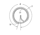
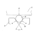
上記装置において、ガイドパイプ7は図3に示すように、支持筒17への巻き角度θを300〜420°とする。また、図4に示すように、ワイヤ送給機構4においてワイヤWをガイドパイプ入り口8へ送給するプレッシャーローラ3のワイヤ送給溝32の角度αは20〜40°とする。
【0013】
このように構成された本発明の装填装置により、ペイルパック内に捩り入り溶接ワイヤを装填する操作について説明する。
駆動モータ6により回転する引き取りキャプスタン2に数回巻かれて送給される溶接用ワイヤWはガイドパイプ7の入り口8から回転軸10に送り込まれる。溶接用ワイヤはこの回転軸を中心として所定の回転速度で回転するガイドパイプ7内を通りペイルパック1の内に水平面に対して傾斜して支持筒17に取り付けられた出口9から送り出される。回転軸10はその中空内部にガイドパイプ7を一体的に取り付け、またその下部において支持筒17を固定懸吊した遊星歯車機構16の軸となっているので、回転軸10、ガイドパイプ7、円板18、遊星軸19aおよび支持筒17は駆動モータ6により駆動され、一体的に所定の回転速度で回転する。
【0014】
ガイドパイプ7の出口9から所定の回転速度で回転しながら送り出されるワイヤWは、回転する該出口9とペイルパック1内のワイヤ積層部W´上端面(装填開始時はペイルパック1底面)との間においてガイド筒21に螺旋状に巻き付きながら順次下方へと移動する。そしてガイド筒21下端に半径方向外方に突出して取り付けた突出部材23によりワイヤ積層部W´の上端面における落下位置を規制され、該上端面にペイルパック内壁に接するワイヤループを形成して着地する。つまりワイヤループはガイド筒21に案内されてその直下へ落ちようとするが、突出部材23があるので全体が該突出部材23側へシフトされ、該部材23はペイルパック1の内壁を指向しているのでループの該部材23と接触した部分がペイルパック1内壁に接触し、反対側の部分はペイルパック1内壁からそのシフト分だけ大きく離れた状態でワイヤ積層部W´の上面に収まる。このときターンテーブル上のペイルパック1は所定の回転速度でゆるやかに回転しているので、ワイヤ積層部W´の上端面に形成するワイヤループは順次その着地点が所定のピッチでずれる。その結果ワイヤWは整然とした花模様を描いて積層されることになる。またペイルパック1はガイドパイプ7の出口9とワイヤ積層部W´上端面との距離が一定となるように降下するので、ワイヤ落下状態は常に安定している。
【0015】
ワイヤWは、ワイヤ送給機構4とワイヤ積層部W´上端面の間において捩りを与えられることになるが、この間におけるワイヤ上端はワイヤ送給機構4に、また下端は積層部W´上端面に固定されているので、ガイドパイプ1回転につき理論上2π(360°)の捩りがワイヤに与えられる。しかし、ガイドパイプ7内で直線状のワイヤWを360°の捩りを与えながら支持筒17の外周に沿って円状にするので、ワイヤは捩り応力と曲げ応力さらにガイドパイプ7内の摩擦抵抗によってワイヤ送給抵抗が高くなり、ワイヤ長手方向の圧縮応力を受けて塑性変形し、ワイヤの捩り角度が溶接時にワイヤ先端が振れる限度である250°未満となる場合がある。そこでワイヤ捩り角度を250°以上とするためにガイドパイプ7の支持筒17への巻き角度θを300〜420°とする。ガイドパイプ7の支持筒17への巻き角度θが300°未満であると、ワイヤ積層部W´上面への着地時に急激にワイヤが曲げられてワイヤ送給抵抗が高くなり、ワイヤ長手方向の圧縮応力を受けて塑性変形して捩り角度が250°未満となる。逆にガイドパイプ7の支持筒17への巻き角度θが420°を超えると、ガイドパイプ7内での摩擦抵抗が大きく、ワイヤ送給抵抗が高くなってワイヤ長手方向の圧縮応力を受けて塑性変形して捩り角度が250°未満となる。
【0016】
また、図4に示したようにワイヤ送給機構4の引き取りキャプスタン2に巻かれた数ターンの内、最終ターンのガイドパイプ入り口8へ送給するワイヤWは、プレッシャーローラ3の外周に硬質ゴム等のリングが嵌められたプレッシャーローラ3のワイヤ送給溝32で押さえられて、ワイヤ積層部W´上面との間で捩りを与えられるが、該ワイヤ送給溝角度αは20〜40°であることが必要である。図5にプレッシャーローラ3のワイヤ送給溝32の拡大図を示す。図中、プレッシャローラ3の押しつけ力がPの場合のワイヤWとプレッシャローラ3の接触圧力RはP/(2 sin(α/2))となり、ワイヤ送給力Fは2μR(μは摩擦係数)で表される。したがって、ワイヤ送給溝角度αが小さいほどワイヤ送給力Fは大きくなる。しかし、ワイヤ送給溝角度αが20°未満であると、プレッシャーローラ3の押しつけ力Pの僅かな変動によってワイヤWがワイヤ径方向に塑性変形して、溶接時に溶接トーチ先端のコンタクトチップで詰まる場合がある。また、ワイヤ送給溝角度αが40°を超えるとワイヤ送給力Fが小さくなり、ワイヤWを十分に押さえきれずにワイヤWが引き取りキャプスタン2とプレッシャーローラ3間でスリップして、装填されたワイヤの捩り角度が250°未満となったり、装填ワイヤのループ径が小さくなって良好な積層状態とならず、溶接時に引き出されたワイヤの先端が振れて溶接位置が一定とならない場合が生じる。
【0017】
なお、ワイヤ送給機構4に送られるワイヤWが曲がっているとガイドパイプ7内で塑性変形しやすくなるので、ワイヤ矯正機等で真直に矯正された状態であることが好ましい。
【0018】
【実施例】
以下、実施例により本発明をさらに詳細に説明する。
まず、JIS Z3313 YFW−C50DRに規定されるワイヤ径1.2〜1.6mmのアーク溶接用フラックス入りワイヤを、図1、図2に示すワイヤ装填装置を用いて、ガイドパイプの支持筒への巻き角度θおよびプレッシャーローラのワイヤ送給溝角度αを種々変えて200kgペイルパックに装填した。その時の装填ワイヤの捩り角度の測定結果(N=5)を表1に示す。
【0019】
【表1】
【0020】
溶接時のワイヤ振れの調査は、ペイルパックから前記フラックス入りワイヤを取り出し、表2に示す条件で鋼種SM490A、板厚12.7mmに溶接長1500mmとし、図6(a)の斜視図に示すように水平すみ肉溶接を各2体表裏(合計6m)を行い、図6(b)の溶接部の断面図に示す下脚の脚長dの最大と最小の差を調べた。なお、評価基準は脚長差が0.5mm以下を○とし、0.5mmを超えたものを×とした。これらの結果を表1にまとめて示す。
【0021】
【表2】
【0022】
表1中試験No.1〜No.4が本発明例、試験No.5〜No.8が比較例である。
本発明例である試験No.1〜No.4は、ガイドパイプの支持筒への巻き角度θおよびワイヤ送給溝角度αともに本発明を満足するので、ペイルパックに装填されたワイヤの捩り角度が250°以上となって、高速度で小脚長のすみ肉溶接条件でペイルパックから引き出して溶接してもワイヤ狙い位置ずれが生じず溶接後の脚長差が少なく極めて満足な結果であった。
【0023】
比較例中試験No.5は、ガイドパイプの支持筒への巻き角度θが小さいのでワイヤ積層部上面への着地時に急激にワイヤが曲げられてワイヤ送給抵抗が高くなりワイヤ長手方向の圧縮応力を受けて塑性変形して捩り角度が250°未満となったので、溶接時にワイヤ先端がわずかに振れて脚長差が0.5mmを超えた。
【0024】
試験No.6は、ガイドパイプの支持筒への巻き角度θが大きいので、ガイドパイプ内での摩擦抵抗が大きくワイヤ送給抵抗が高くなってワイヤ長手方向の圧縮応力を受けて塑性変形して捩り角度が250°未満となったので、溶接時にワイヤ先端がわずかに振れて脚長差が0.5mmを超えた。
試験No.7は、ワイヤ送給溝角度αが小さいので、ワイヤが部分的にワイヤ径方向に塑性変形して溶接時にコンタクトチップに詰まって溶接が中断した。
【0025】
試験No.8はワイヤ送給溝角度αが大きいので、ワイヤを十分に押さえきれずに引き取りキャプスタンとプレッシャーローラ間でスリップして、装填されたワイヤの捩り角度が250°未満となって、溶接時にワイヤ先端がわずかに振れて脚長差が0.5mmを超えた。なお、No.8はワイヤ装填時に引き取りキャプスタンとプレッシャーローラ間でスリップしたので、ワイヤ積層部のループ径が小さくなった箇所が一部生じた。
【0026】
【発明の効果】
以上詳述したように本発明の溶接用ワイヤの装填装置によれば、ワイヤの捩り角度を均一かつ確実に与えてペイルパックに装填できる。したがって、取り出し時にワイヤ先端が振れることがなく、高速度で小脚長のすみ肉溶接においても均一な脚長が得られる。
【図面の簡単な説明】
【図1】本発明装置の一実施例を示す全体側面図で、一部断面図で示し、下部は図2に連続する。
【図2】本発明装置の一実施例を示す全体側面図で、一部断面図で示し、上部は図1に連続する。
【図3】本発明のガイドパイプの支持筒への巻き角度θを示す平面図
【図4】本発明のプレッシャーローラ溝角度αを示す断面図
【図5】本発明のプレッシャーローラのワイヤ送給溝の拡大図
【図6】本発明の実施例における(a)はすみ肉溶接を示す斜視図、(b)はすみ肉溶接部の脚長を示す断面図
【符号の説明】
1 ペイルパック
2 引き取りキャプスタン
3 プレッシャーローラ
4 ワイヤ送給機構
5 ベルト
6 駆動モータ
7 ガイドパイプ
8 ガイドパイプの入り口
9 ガイドパイプの出口
10 回転軸
11 固定支持架台
12、13 プーリ
14 ベルト
15 減速機
16 遊星歯車機構
17 支持軸
18 円板
19 遊星歯車
19a 遊星軸
20a 上部内歯車
20b 下部内歯車
21 ガイド筒
22 支持筒
23 突出部材
24 ターンテーブル
25 昇降機構
26 昇降台
27、28 プーリ
29 ベルト
30 減速機
31 駆動モータ
32 ワイヤ送給溝
W ワイヤ
W´ ワイヤ積層部[0001]
TECHNICAL FIELD OF THE INVENTION
The present invention relates to an apparatus for loading a welding wire into a pail pack, and more particularly to an apparatus for loading a welding wire capable of uniformly and reliably giving a wire twist angle.
[0002]
[Prior art]
Generally, a pail pack is used as a storage container for a large-capacity welding wire. The wire is taken out from the pail pack at the time of welding, the wire loop laminate is taken out from the upper loop in order to the outside of the pail pack, and if necessary, the bending habit is removed with a wire straightener and then to the welding torch with a conduit tube. It is performed in the order of leading. However, since the wire thus taken out is subjected to 360 ° torsion per one turn at the time of being taken out, the tip of the wire to be welded out of the welding torch warps, the welding point fluctuates, and the weld bead is meandered. There is.
[0003]
Therefore, as proposed in Japanese Patent Application Laid-Open No. Sho 60-133919 and Japanese Patent Publication No. Sho 62-825, when a welding wire is loaded in a pail pack, reverse twisting is applied to the wire in advance within the elastic limit. In practice, it is practical to load the pail pack with this reverse twist, cancel the torsion received at this time and the torsion held during loading at the time of removal, and eliminate the twist from the wire coming out of the welding torch. Has been
[0004]
[Problems to be solved by the invention]
However, in the above-mentioned method of loading a pail pack, the wire is plastically deformed due to a plastic deformation of the wire due to about 360 ° of torsion and bending when the wire is loaded and a compressive stress in the longitudinal direction of the wire due to frictional resistance during feeding into the pail pack. A great twist angle could not be obtained. In addition, there has been a case where the wire is slipped in the wire feeding mechanism, the wire feeding speed fluctuates, and a uniform torsion angle cannot be obtained.
[0005]
Therefore, there is a problem that the wire tip slightly fluctuates and the welding point fluctuates, so that a uniform leg length cannot be obtained at the time of takeout, particularly when small fillet length fillet welding is performed at a high speed.
Therefore, an object of the present invention is to provide a welding wire loading apparatus capable of uniformly and reliably giving a wire twist angle and loading the same in a pail pack.
[0006]
[Means for Solving the Problems]
That is, the gist of the present invention is to provide a wire feeding mechanism for feeding a wire in a welding wire loading device for laminating and storing a twisted welding wire in a pail pack in a loop shape. A guide pipe having an outlet in the pail pack with an inlet at the wire outlet of the mechanism and a lower spiral guide pipe, and a support pipe that rotates while supporting the guide pipe on the outer surface are arranged. A welding wire loading device, wherein the winding angle is 300 to 420 °. Further, the wire feeding mechanism here comprises a take-up capstan and a pressure roller, and the pressure roller has a wire feeding groove angle of 20 to 40 °.
[0007]
BEST MODE FOR CARRYING OUT THE INVENTION
Hereinafter, the present invention will be described based on specific examples shown in the drawings. 1 and 2 are overall side views showing an example of the device of the present invention, and a part thereof is shown in cross section. One drawing is constructed by connecting FIG. 1 to the upper part of FIG. In these figures, W is a welding wire sent from a wire supply source such as a wire drawing machine or a bobbin (not shown), and the wire W includes a take-up capstan 2 for winding the wire W several times and a pressure roller 3. The wire is pulled out from the wire supply source by the wire feeding mechanism 4 and is fed into the pail pack 1. The take-off capstan 2 is driven by a drive motor 6 via a belt 5 and rotates, and the rotation speed determines the feeding speed of the wire W sent into the pail pack 1.
[0008]
Reference numeral 7 denotes a guide pipe for guiding the wire W from the capstan 2 to the pail pack 1. The entrance 8 of the guide pipe is located at the position of the rotating shaft 10 and near the take-up capstan 2, and the outlet 9 is inclined with respect to the horizontal plane. Then go into Pail Pack 1. The upper part of the guide pipe 7 is integrally attached to the hollow interior of the rotating shaft 10, and the rotating shaft 10 is attached to the fixed support base 11 via bearings, and via pulleys 12 and 13, a belt 14, and a speed reducer 15. The drive motor 6 rotates at a speed linked to the wire feeding speed. The lower portion of the guide pipe 7 is spirally wound around the outer surface of a support cylinder 17 attached to a planetary gear mechanism 16 having the rotation shaft 10 as an axis.
[0009]
The planetary gear mechanism 16 has a plurality of planetary shafts 19a having planetary gears 19 arranged at upper and lower ends mounted on a pair of disks 18 fixed to the rotating shaft 10 via bearings, and an upper internal gear 20a meshing with the planetary gears 19. The lower internal gear 20b is provided on the upper and lower portions. The upper internal gear 20a is fixed to the support base 11, and the lower internal gear 20b is fixed to a support cylinder 22 of a guide cylinder 21 suspended via a bearing at the lower end of the rotating shaft 10. Thus, the support cylinder 22 is supported and suspended on the rotating shaft 10 in a stationary state. The support cylinder 22 to which the lower internal gear 20b of the planetary gear mechanism 16 is fixed at the upper part is attached to the lower part thereof so that the guide cylinder 21 for guiding the wire coming out of the guide pipe outlet 9 is located at the center in the pail pack 1. Have been.
[0010]
The guide tube 21 has a cylindrical shape having substantially the same diameter as the rotation diameter of the outlet 9 of the guide pipe. Have been. The projecting member 23 regulates the drop position of the wire that drops out of the guide pipe outlet 9 and spirals while being wound around the guide tube, so that the wire loop that lands at the upper end of the wire stacking portion W ′ contacts the inner wall of the pail pack 1. It is for doing.
[0011]
The pail pack 1 is mounted on a turntable 24. The turntable 24 is mounted on a lift 26 of a lift mechanism 25 via bearings, and is driven via pulleys 27 and 28, a belt 29, and a speed reducer 30. The motor 31 rotates at a predetermined rotation speed. The elevating device 25 keeps the distance between the outlet 9 of the guide pipe of the wire W and the upper end surface of the wire stacking portion W ′ in the pail pack 1, that is, the distance between the lower end of the guide tube 21 and the upper end surface of the wire stacking portion constant. In order to hold, the pile pack 1 is gradually lowered in the vertical direction at a predetermined speed as the height of the laminated portion W ′ increases.
[0012]
In the above apparatus, as shown in FIG. 3, the guide pipe 7 has a winding angle θ around the support cylinder 17 of 300 to 420 °. As shown in FIG. 4, the angle α of the wire feed groove 32 of the pressure roller 3 for feeding the wire W to the guide pipe inlet 8 in the wire feed mechanism 4 is set to 20 to 40 °.
[0013]
An operation of loading the twisted welding wire into the pail pack by the loading device of the present invention configured as described above will be described.
The welding wire W wound and fed several times around the take-up capstan 2 rotated by the drive motor 6 is fed into the rotary shaft 10 from the entrance 8 of the guide pipe 7. The welding wire passes through a guide pipe 7 which rotates at a predetermined rotation speed about this rotation axis, and is fed into the pail pack 1 from an outlet 9 attached to a support cylinder 17 while being inclined with respect to a horizontal plane. The rotary shaft 10 is integrally mounted with the guide pipe 7 in the hollow interior thereof, and serves as a shaft of a planetary gear mechanism 16 in which a support cylinder 17 is fixedly suspended at a lower portion thereof. The plate 18, the planet shaft 19a, and the support cylinder 17 are driven by the drive motor 6, and rotate integrally at a predetermined rotation speed.
[0014]
The wire W sent out while rotating at a predetermined rotation speed from the outlet 9 of the guide pipe 7 is connected to the rotating outlet 9 and the upper end surface of the wire lamination portion W ′ in the pail pack 1 (the bottom surface of the pail pack 1 at the start of loading). And move downward sequentially while spirally winding around the guide tube 21. A drop position on the upper end surface of the wire stacking portion W 'is regulated by a projecting member 23 which is attached to the lower end of the guide cylinder 21 so as to protrude outward in the radial direction, and a wire loop is formed on the upper end surface so as to be in contact with the inner wall of the pail pack. I do. In other words, the wire loop is guided by the guide tube 21 and tends to fall directly below the guide tube 21. However, since the projecting member 23 is provided, the whole is shifted toward the projecting member 23, and the member 23 is directed toward the inner wall of the pail pack 1. Therefore, the portion of the loop that comes into contact with the member 23 comes into contact with the inner wall of the pail pack 1, and the opposite portion fits on the upper surface of the wire stacking portion W ′ while being far away from the inner wall of the pail pack 1 by the amount of the shift. At this time, since the pail pack 1 on the turntable is gently rotating at a predetermined rotation speed, the landing points of the wire loops formed on the upper end surface of the wire lamination portion W 'are sequentially shifted at a predetermined pitch. As a result, the wires W are stacked in an orderly flower pattern. Further, since the pail pack 1 descends so that the distance between the outlet 9 of the guide pipe 7 and the upper end face of the wire lamination portion W 'is constant, the wire falling state is always stable.
[0015]
The wire W is torsioned between the wire feeding mechanism 4 and the upper end face of the wire stacking portion W ′, and the upper end of the wire between the wire W and the wire feeding mechanism 4 and the lower end is the upper end face of the stacking section W ′. , A theoretical twist of 2π (360 °) per rotation of the guide pipe is imparted to the wire. However, since the linear wire W is made circular along the outer circumference of the support cylinder 17 while giving a 360 ° torsion in the guide pipe 7, the wire is subjected to torsional stress and bending stress and frictional resistance in the guide pipe 7. In some cases, the wire feeding resistance increases, undergoes plastic deformation due to the compressive stress in the longitudinal direction of the wire, and the torsion angle of the wire becomes less than 250 °, which is the limit at which the wire tip swings during welding. Therefore, in order to make the wire twist angle 250 ° or more, the winding angle θ of the guide pipe 7 around the support cylinder 17 is set to 300 to 420 °. If the winding angle θ of the guide pipe 7 around the support cylinder 17 is less than 300 °, the wire is sharply bent at the time of landing on the upper surface of the wire lamination portion W ′, so that the wire feeding resistance increases and the compression in the wire longitudinal direction is increased. Plastic deformation occurs under stress, and the torsional angle becomes less than 250 °. On the other hand, if the winding angle θ of the guide pipe 7 around the support cylinder 17 exceeds 420 °, the frictional resistance in the guide pipe 7 is large, the wire feed resistance is increased, and the wire receives compressive stress in the longitudinal direction of the wire, resulting in plasticity. It deforms and the torsion angle becomes less than 250 °.
[0016]
As shown in FIG. 4, the wire W fed to the guide pipe entrance 8 in the last turn of the several turns wound around the take-up capstan 2 of the wire feeding mechanism 4 is hard on the outer periphery of the pressure roller 3. Pressing is performed by the wire feed groove 32 of the pressure roller 3 in which a ring of rubber or the like is fitted, and a twist is given to the upper surface of the wire lamination portion W ′. The wire feed groove angle α is 20 to 40 °. It is necessary to be. FIG. 5 shows an enlarged view of the wire feed groove 32 of the pressure roller 3. In the figure, when the pressing force of the pressure roller 3 is P, the contact pressure R between the wire W and the pressure roller 3 is P / (2 sin (α / 2)), and the wire feeding force F is 2 μR (μ is a friction coefficient). Is represented by Therefore, the wire feeding force F increases as the wire feeding groove angle α decreases. However, if the wire feed groove angle α is less than 20 °, the wire W is plastically deformed in the wire radial direction due to a slight change in the pressing force P of the pressure roller 3, and is clogged by the contact tip at the tip of the welding torch during welding. There are cases. If the wire feed groove angle α exceeds 40 °, the wire feed force F becomes small, and the wire W cannot be sufficiently pressed down, and the wire W slips between the take-up capstan 2 and the pressure roller 3 to be loaded. When the twist angle of the wire is less than 250 ° or the loop diameter of the loaded wire is small and the laminated state is not good, the tip of the wire pulled out at the time of welding may swing and the welding position may not be constant. .
[0017]
If the wire W sent to the wire feeding mechanism 4 is bent, the wire W is likely to be plastically deformed in the guide pipe 7. Therefore, it is preferable that the wire W is straightened by a wire straightening machine or the like.
[0018]
【Example】
Hereinafter, the present invention will be described in more detail with reference to examples.
First, a flux-cored wire for arc welding having a wire diameter of 1.2 to 1.6 mm specified in JIS Z3313 YFW-C50DR is used to attach a guide pipe to a support cylinder of a guide pipe by using a wire loading device shown in FIGS. The 200 kg pile pack was loaded with the winding angle θ and the wire feed groove angle α of the pressure roller varied. Table 1 shows the measurement results (N = 5) of the twist angle of the loading wire at that time.
[0019]
[Table 1]
[0020]
Investigation of wire run-out during welding was performed by taking out the flux-cored wire from the pail pack, setting the steel type to SM490A, setting the plate thickness to 12.7 mm, and setting the welding length to 1500 mm under the conditions shown in Table 2, as shown in the perspective view of FIG. Then, two horizontal fillet welds were performed on each side (6 m in total), and the difference between the maximum and minimum leg length d of the lower leg shown in the sectional view of the welded portion in FIG. 6B was examined. The evaluation criteria were as follows: ○ when the leg length difference was 0.5 mm or less, and × when the difference exceeded 0.5 mm. The results are summarized in Table 1.
[0021]
[Table 2]
[0022]
Test No. 1 in Table 1. 1 to No. 4 is an example of the present invention, Test No. 5-No. 8 is a comparative example.
Test No. which is an example of the present invention. 1 to No. No. 4 satisfies both the winding angle θ of the guide pipe around the support cylinder and the wire feeding groove angle α, so that the twist angle of the wire loaded in the pail pack is 250 ° or more, and the wire is small at high speed. Even when pulled out from the pail pack and welded under the fillet welding condition of the leg length, the wire aiming position did not shift and the leg length difference after welding was small, which was a very satisfactory result.
[0023]
Test No. in the comparative example. In No. 5, since the winding angle θ of the guide pipe around the support cylinder is small, the wire is sharply bent at the time of landing on the upper surface of the wire stacking portion, the wire feeding resistance increases, and the wire undergoes a compressive stress in the longitudinal direction of the wire and is plastically deformed. Since the torsion angle was less than 250 °, the wire tip slightly swung during welding, and the leg length difference exceeded 0.5 mm.
[0024]
Test No. In No. 6, since the winding angle θ of the guide pipe around the support cylinder is large, the frictional resistance in the guide pipe is large and the wire feeding resistance is increased, and the wire is plastically deformed by receiving a compressive stress in the longitudinal direction of the wire and the torsion angle is increased. Since the angle was less than 250 °, the wire tip slightly swung during welding, and the leg length difference exceeded 0.5 mm.
Test No. In No. 7, since the wire feed groove angle α was small, the wire was partially plastically deformed in the radial direction of the wire, clogged the contact tip during welding, and the welding was interrupted.
[0025]
Test No. No. 8 has a large wire feed groove angle α, so that the wire cannot be sufficiently held down and slips between the take-up capstan and the pressure roller, and the twist angle of the loaded wire becomes less than 250 °. The tip slightly swung and the leg length difference exceeded 0.5 mm. In addition, No. 8 slipped between the take-up capstan and the pressure roller when the wire was loaded, so that a portion of the wire lamination portion where the loop diameter became small occurred.
[0026]
【The invention's effect】
As described in detail above, according to the welding wire loading device of the present invention, the torsion angle of the wire can be given uniformly and reliably to be loaded into the pail pack. Therefore, the tip of the wire does not swing at the time of removal, and a uniform leg length can be obtained even in high-speed small-hole length fillet welding.
[Brief description of the drawings]
FIG. 1 is an overall side view showing one embodiment of the device of the present invention, which is shown in a partial cross-sectional view, and a lower portion is continuous with FIG.
FIG. 2 is an overall side view showing one embodiment of the device of the present invention, which is shown in a partial cross-sectional view, and the upper portion is continuous with FIG.
3 is a plan view showing a winding angle θ of a guide pipe of the present invention around a support cylinder. FIG. 4 is a cross-sectional view showing a pressure roller groove angle α of the present invention. FIG. 5 is a wire feed of a pressure roller of the present invention. FIG. 6 is a perspective view showing a fillet weld in an embodiment of the present invention, and FIG. 6 (b) is a sectional view showing a leg length of a fillet weld.
REFERENCE SIGNS LIST 1 Pail pack 2 Pick-up capstan 3 Pressure roller 4 Wire feeding mechanism 5 Belt 6 Drive motor 7 Guide pipe 8 Guide pipe entrance 9 Guide pipe exit 10 Rotary shaft 11 Fixed support gantry 12, 13 Pulley 14 Belt 15 Reduction gear 16 Planetary gear mechanism 17 Support shaft 18 Disk 19 Planetary gear 19a Planetary shaft 20a Upper internal gear 20b Lower internal gear 21 Guide cylinder 22 Support cylinder 23 Projection member 24 Turntable 25 Lifting mechanism 26 Lifting tables 27, 28 Pulley 29 Belt 30 Reduction gear 31 Drive motor 32 Wire feed groove W Wire W 'Wire lamination