JP3576349B2 - Equipment with blower - Google Patents
Equipment with blower Download PDFInfo
- Publication number
- JP3576349B2 JP3576349B2 JP08994197A JP8994197A JP3576349B2 JP 3576349 B2 JP3576349 B2 JP 3576349B2 JP 08994197 A JP08994197 A JP 08994197A JP 8994197 A JP8994197 A JP 8994197A JP 3576349 B2 JP3576349 B2 JP 3576349B2
- Authority
- JP
- Japan
- Prior art keywords
- frame
- base
- fan case
- hydraulic
- upright frame
- Prior art date
- Legal status (The legal status is an assumption and is not a legal conclusion. Google has not performed a legal analysis and makes no representation as to the accuracy of the status listed.)
- Expired - Fee Related
Links
Images


Description
【0001】
【発明の属する技術分野】
この発明は、圃場に薬剤を散布する薬剤散布機や落ち葉の吹き集め等の風を吐出するブロワ等の送風機付き装置に係り、詳しくは上下方向及び水平方向へ送風機の向きを調整できる送風機付き装置に関するものである。
【0002】
【従来の技術】
特公平4−76743号公報の薬剤散布装置では、ファン及びそれを駆動する油圧モータを収容するファンケースを所定高さに保持しつつ、ファンケースの吐出側開口の向きを上下方向及び左右方向へ変更できるようにしている。このような薬剤散布装置では、油圧ポンプとファンケース内の油圧モータとの間での油圧の給排のために、油圧ホースが配管されている。
【0003】
【発明が解決しようとする課題】
従来の薬剤散布装置では、油圧ホースの配管について特に考慮されていない。油圧ホースは、高圧の油圧を導くので、強度を確保するために、可撓性が低下しており、無理に捻られると、耐久性が悪化する。
【0004】
この発明の目的は、ファンケースの送風機の向きの変更に円滑に対応しつつ、油圧ホースの耐久性低下を防止できる送風機付き装置を提供することである。
【0005】
【課題を解決するための手段】
【0006】
この発明の送風機付き装置(10)は次の(a)〜(e)を有している。
(a)軸方向両端を開口し内部にファン及びそれを駆動する油圧モータを収容しているファンケース(30)
(b)上端部においてファンケース(30)を水平線の周りに回転自在に支持している起立枠(28)
(c)ファンケース(30)の吐出側開口(32)が左向きと右向きとの間で鉛直線の周りに回転するように起立枠(28)の下端部を支持している台部(22)
(d)台部(22)に装備される油圧ポンプ
(e)起立枠(28)の一方の側部に沿って上昇して油圧ポンプと油圧モータとを接続しファンケース(30)の吐出側開口(32)の左右の一方の向きではほぼ1回巻きの状態になり他方の向きではその巻きを解除される油圧ホース(50)
を有している。
【0007】
ファンケース(30)は、起立枠(28)の上端部におけるほぼ水平線の周りの回転により上下方向へ揺動し、また、ほぼ鉛直線の周りの台部(22)に対する起立枠(28)の回転により水平方向へ揺動する。油圧ホース(50)は、ファンケース(30)と台部(22)とを接続しているので、台部(22)に対するファンケース(30)の相対変位に伴い、捻られるが、ファンケース(30)の吐出側開口(32)の左右の一方及び他方の向きでそれぞれ1回巻き状態及び巻き解除状態になり、捻じれは最小限に限定される。これにより、油圧ホース(50)は、台部(22)に対するファンケース(30)の相対変位に追従しつつ,耐久性低下を防止される。
【0008】
この発明の他の送風機付き装置(10)によれば、さらに、起立枠(28)は、ファンケース(30)の下方において台部(22)の横断方向へ延びる横断部(42)をもつ。ループ状ホースガイド(56)は、横断部(42)に取り付けられて、油圧ホース(50)を通り抜けさせている。
【0009】
ループ状ホースガイド(56)は、ほぼ鉛直線の周りに起立枠(28)と一体に揺動するとともに、ファンケース(30)の下側において、油圧ホース(50)を通り抜けさせて、通り抜け位置を規定する。これにより、油圧ホース(50)の巻き状態及び巻き解除状態の切替は円滑化する。
【0010】
この発明の他の送風機付き装置(10)は、さらに、起立枠(28)に固定され台部(22)にほぼ鉛直線の周りに回転自在に枢支されるベース(58)、一端側においてほぽ鉛直線の周りに回転自在に台部(22)に枢支されるアーム(68)、一端側及び中間部においてそれぞれ起立枠(28)及びアーム(68)の他端側に回転自在に枢支されているリンク(64)、及び両端部をそれぞれリンク(64)の他端側及び台部(22)に回転自在に枢支されている旋回用シリンダ(74)を有している。
【0011】
ベース(58)、アーム(68)、及びリンク(64)の結合点は四節回転連鎖(86)を構成する。四節回転連鎖(86)を使用して、起立枠(28)をほぼ鉛直線の周りに回動することにより、旋回用シリンダ(74)の等速の伸縮に対する起立枠(28)の各回転位置の回転速度を適正値になるように、設定できる。
【0012】
この発明の他の送風機付き装置(10)によれば、さらに、台部(22)はフレーム材(46)から成る。油圧ホース(50)は、上方視、フレーム材(46)と旋回用シリンダ(74)との間でかつ起立枠(28)の旋回時の運動要素の運動範囲と重ならない範囲(84)を上下方向へ通過している。
【0013】
油圧ホース(50)は、ファンケース(30)から油圧ポンプへ向かう途中、ベース(58)、アーム(68)、リンク(64)、及び旋回用シリンダ(74)の高さを上下方向へ通過しなければならない。油圧ホース(50)は、範囲(84)を通過することにより、その高さの通過部位を適切に設定される。
【0014】
この発明の送風機付き装置(10)は次の(a)〜(f)を有している。
(a)三点リンク(14)を介して自走車(12)に連結される車輪付き台車(22)
(b)車輪付き台車(22)に配設され自走車(12)のPTO軸(20)の動力を介して駆動される油圧ポンプ
(c)軸方向両端を開口し内部にファン及びそれを駆動する油圧モータを収容しているファンケース(30)
(d)上端部においてファンケース(30)を水平線の周りに回転自在に支持しファンケース(30)の吐出側開口(32)が左向きと右向きとの間で鉛直線の周りに回転するように下端部において車輪付き台車(22)に支持される起立枠(28)
(e)車輪付き台車(22)に装備される油圧ポンプ
(f)起立枠(28)の一方の側部に沿って上昇して油圧ポンプと油圧モータとを接続する油圧ホース(50)
を有している。
【0015】
従来の送風機付き装置は、自走車(12)に直接組み付けられているのに対し、この送風機付き装置(10)は、農業用トラクタ等の自走車(12)に三点リンク(14)を介して連結される方式であるので、組付け型に比して効率的な運用及び装置の簡単化を図ることができる。
【発明の実施の形態】
以下、発明の実施の形態について図面を参照して説明する。
図2は散布装置10及び農業用トラクタ12を連結状態で示す側面図である。農業用トラクタ12は、後部に三点リンク14及び26を備え、三点リンク14は、1個のアッパリンク16と、2個のロアリンク18とを有している。散布装置10のフレーム台22は、前後左右に計4個のキャスタ24を有し、三点リンク14を介して農業用トラクタ12へ連結される。油圧ポンプは、フレーム台22内に配設され、PTO軸20からの回転動力により駆動される。支持フレーム28は、フレーム台22から起立し、上端部においてファンケース30を水平線の周りに傾動自在に支持している。傾動用油圧シリンダ29は、、油圧ホース50とは反対側のファンケース30の側部側に設置され、伸縮によりファンケース30の傾動角を水平面に対して+−所定範囲で調整する。
【0016】
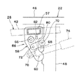
図1は散布装置10の主要部の斜視図である。ファンケース30は、軸方向両端を吸入側開口31及び吐出側開口32として開口し、吐出側開口32側の半部は吐出側開口32の方へ径を漸減するテーパとしており、吸入側開口31より吐出側開口32の面積を縮小されている。環状ノズルパイプ34は、吐出側開口32の周縁に沿って延び、複数個のノズル36は、等間隔で環状ノズルパイプ34に取付けられている。直線状ノズルパイプ38は、吐出側開口32の水平方向の直径に沿って吐出側開口32を横断し、2個のノズル40は、吐出側開口32のほぼ中心部において直線状ノズルパイプ38に取付けられている。ファンケース30内には、ファン及びファンを駆動する油圧モータ(共に図示せず)が収容される。
【0017】
支持フレーム28は、ファンケース30の下側の水平枠部42と、水平枠部42の両端から起立して上端部においてファンケース30の両側部に達してファンケース30を水平線の周りに回動自在に支持する鉛直枠部44とを備えている。フレーム台22は、前後方向へ延びる左右のサイドフレーム46と、両サイドフレーム46を連結する中間部横フレーム48とを有している。油圧ホース50は、給排の2本とドレンの1本との計3本から成り、上端部においてファンケース30内の油圧モータに接続され、中間部において一方の鉛直枠部44の外側から内側へ回り込み、下端部においてフレーム台22内の油圧ポンプ及びオイルタンクに接続される。液体ホース52は、環状ノズルパイプ34用と直線状ノズルパイプ38用との2本存在し、上端部において環状ノズルパイプ34及び直線状ノズルパイプ38に接続され、下端部の接続口54は一方の鉛直枠部44の下端部に位置している。ガイド55は、水平枠部42の中心に対して傾動用油圧シリンダ29側の鉛直枠部44に少し偏倚した位置で水平枠部42から起立し、上端部に円環56を備えている。油圧ホース50は円環56を通されている。
【0018】
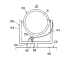
図3は支持フレーム28と中間部横フレーム48との結合部の詳細図である。垂下フレーム57は水平枠部42の中心部の下面から垂下し、張出し板58は、垂下フレーム57の下端に固定されつつ、中間部横フレーム48の方へ張り出し、鉛直方向の周りに回転自在に結合軸60により中間部横フレーム48に支持されている。垂下棒62は、水平枠部42の下面から垂下し、「く」字形のリンクプレート64は、一端部において結合軸66により垂下棒62に鉛直線の周りに回転自在に結合している。アーム68は、結合軸70により鉛直線の周りに回転自在に中間部横フレーム48に結合し、結合軸72により鉛直線の周りに回転自在にリンクプレート64の中間部に結合している。旋回用油圧シリンダ74は、後端部において鉛直線の周りに回転自在にフレーム台22の後部横フレーム76に結合し、前端部において結合軸78により鉛直線の周りに回転自在にリンクプレート64の他端部に結合している。範囲84は、上方から見て、フレーム台22のサイドフレーム46、中間部横フレーム48、及び後部横フレーム76により囲われる範囲で、かつ旋回用油圧シリンダ74の伸縮に伴う支持フレーム28の運動中に支持フレーム28や旋回用油圧シリンダ74等の運動要素の運動範囲と重ならない範囲となっている。
【0019】
図4は支持フレーム28と中間部横フレーム48との結合部の図3とは別の角度から見た図である。切欠き80は、張出し板58に形成され、結合軸70と張出し板58との干渉を回避する。切欠き82は、垂下フレーム57に形成され、垂下フレーム57とリンクプレート64との干渉を回避する。
【0020】
図5は支持フレーム28と中間部横フレーム48との結合部を上方から見た図である。結合軸60,66,70,72は四節回転連鎖86を構成する。
【0021】
この散布装置10は、旋回用油圧シリンダ74の伸縮により支持フレーム28を鉛直線の周りに回動させ、これにより、ファンケース30の吐出側開口32を真後ろ向きを中心に左右の所定範囲内で変更できる。また、ファンケース30は傾動用油圧シリンダ29の伸縮により水平面に対する傾動角を変更し、これにより、吐出側開口32の向きを上下方向へ所定範囲で変更できる。散布装置10は、ノズル36,40から薬液又は水を噴射して、薬液散布機、潅水装置、さらには、細霧を芝上部等に散布して冷房する細霧冷房機等として使用される。また、ノズル36,40からの液体散布を中止して、ファンケース30内のファンだけを駆動させて、風力により落ち葉等を吹き集めたり、枯れ葉を飛ばしたりするブロワ等としても使用される。
【0022】
図6は結合軸66を結合軸60に対して10°ずつ回転したときの結合軸72,78の軌跡上の位置を示している。旋回用油圧シリンダ74の伸縮により結合軸66が結合軸60に対して回転し、結果、支持フレーム28がフレーム台22に対して鉛直線の周りを回動する。こうして、ファンケース30の吐出側開口32の向きを、散布装置10の真後ろ向きを中心に左右の範囲で変更できる。旋回用油圧シリンダ74の伸縮に対して、A,B,Cはそれぞれ結合軸66,78,72の軌跡を示している。A上に10°間隔に取られた結合軸66の位置に対して、B上の結合軸78の各位置は、Bの両端において疎で、中央部において密になっている。したがって、結合軸78を等速で伸張している場合、結合軸66は、Aの両端範囲で低速で回転し、Aの中央範囲で高速で回転する。
【0023】
図7はファンケース30が吐出側開口32を右へ向けたときの油圧ホース50の状態をフレーム台22の右方から見た図、図8はファンケース30が吸入側開口31を右へ向けたとき(=吐出側開口32を左へ向けたとき)の油圧ホース50の状態をフレーム台22の右方から見た図である。ファンケース30が吐出側開口32を右へ向けているときには、油圧ホース50は1回巻きの状態となっており、ファンケース30が吐出側開口32を左へ向けているときには、油圧ホース50は巻きを解除されて延びた状態となっている。これにより、支持フレーム28の左右の回転に伴う油圧ホース50の捻りは抑制され、油圧ホース50の耐久性低下を防止できる。
【図面の簡単な説明】
【図1】散布装置の主要部の斜視図である。
【図2】散布装置及び農業用トラクタを連結状態で示す側面図である。
【図3】支持フレームと中間部横フレームとの結合部の詳細図である。
【図4】支持フレームと中間部横フレームとの結合部の図3とは別の角度から見た図である。
【図5】支持フレームと中間部横フレームとの結合部を上方から見た図である。
【図6】結合軸を結合軸に対して10°ずつ回転したときの各結合軸の軌跡上の位置を示す図である。
【図7】ファンケースが吐出側開口を右へ向けたときの油圧ホースの状態をフレーム台の右方から見た図である。
【図8】ファンケースが吸入側開口を右へ向けたときの油圧ホースの状態をフレーム台の右方から見た図である。
【符号の説明】
10 散布装置(送風機付き装置)
12 農業用トラクタ(車輪付き台車)
14 三点リンク
20 PTO軸
22 フレーム台(車輪付き台車、台部)
28 支持フレーム(起立枠)
30 ファンケース
32 吐出側開口
42 水平枠部(横断部)
46 サイドフレーム
50 油圧ホース
56 円環(ループ状ホースガイド)
58 張出し板(ベース)
64 リンクプレート(リンク)
68 アーム
74 旋回用油圧シリンダ(旋回用シリンダ)
84 範囲
86 四節回転連鎖[0001]
TECHNICAL FIELD OF THE INVENTION
The present invention relates to a device with a blower such as a medicine sprayer for spraying a medicine on a field or a blower for discharging wind such as blow-collecting of fallen leaves, and more particularly to a device with a blower capable of adjusting the direction of the blower in the vertical and horizontal directions. It is about.
[0002]
[Prior art]
In the medicine spraying device disclosed in Japanese Patent Publication No. 4-76743, the direction of the discharge side opening of the fan case is changed in the vertical and horizontal directions while maintaining the fan and the fan case accommodating the hydraulic motor for driving the fan at a predetermined height. Make changes possible. In such a medicine spraying apparatus, a hydraulic hose is provided for supplying and discharging hydraulic pressure between a hydraulic pump and a hydraulic motor in a fan case.
[0003]
[Problems to be solved by the invention]
In the conventional medicine spraying device, piping of the hydraulic hose is not particularly considered. Since the hydraulic hose guides a high-pressure hydraulic pressure, its flexibility is reduced in order to secure strength, and if it is forcibly twisted, its durability is deteriorated.
[0004]
SUMMARY OF THE INVENTION It is an object of the present invention to provide a device with a blower which can smoothly cope with a change in the direction of a blower of a fan case and can prevent a decrease in durability of a hydraulic hose.
[0005]
[Means for Solving the Problems]
[0006]
The device (10) with a blower of the present invention has the following (a) to (e).
(A) A fan case (30) having both ends opened in the axial direction and containing a fan and a hydraulic motor for driving the fan inside
(B) an upright frame (28) that rotatably supports a fan case (30) around a horizontal line at an upper end portion;
(C) A base (22) supporting the lower end of the upright frame (28) such that the discharge-side opening (32) of the fan case (30) rotates around a vertical line between left and right.
(D) a hydraulic pump (e) mounted on the base (22), ascending along one side of the upright frame (28), connecting the hydraulic pump and the hydraulic motor, and connecting the hydraulic pump and the hydraulic motor to the discharge side of the fan case (30). A hydraulic hose (50) that is wound substantially once in one of the left and right directions of the opening (32) and is unwound in the other direction.
have.
[0007]
The fan case (30) swings up and down by rotation about an almost horizontal line at the upper end of the upright frame (28), and the upright frame (28) moves relative to the base (22) about a substantially vertical line. It swings horizontally by rotation. Since the hydraulic hose (50) connects the fan case (30) and the base (22), the hydraulic hose (50) is twisted with the relative displacement of the fan case (30) with respect to the base (22). In the one side and the other side of the left and right sides of the discharge side opening (32) of 30), the winding is in the once-wound state and the unwound state, respectively, and the twist is limited to a minimum. Thus, the hydraulic hose (50) follows the relative displacement of the fan case (30) with respect to the pedestal (22), and prevents a decrease in durability.
[0008]
According to another device with a blower (10) of the present invention, the upright frame (28) further has a transverse portion (42) extending in a transverse direction of the base portion (22) below the fan case (30). A loop hose guide (56) is attached to the cross section (42) and passes through the hydraulic hose (50).
[0009]
The loop-shaped hose guide (56) swings integrally with the upright frame (28) around a substantially vertical line, and passes through the hydraulic hose (50) below the fan case (30), so that the loop-shaped hose guide (56) passes therethrough. Is defined. Thereby, the switching between the wound state and the unwound state of the hydraulic hose (50) is facilitated.
[0010]
Another device (10) with a blower according to the present invention further comprises a base (58) fixed to the upright frame (28) and rotatably supported on the base (22) substantially around a vertical line at one end. An arm (68) pivotally supported on the base (22) so as to be rotatable about a vertical line, and rotatably mounted on the upright frame (28) and the other end of the arm (68) at one end and an intermediate portion, respectively. A link (64) is pivotally supported, and a turning cylinder (74) is rotatably supported at both ends by the other end of the link (64) and the base (22).
[0011]
The junction of the base (58), arm (68) and link (64) forms a four-bar swivel chain (86). By rotating the upright frame (28) about a vertical line using a four-bar rotating chain (86), each rotation of the upright frame (28) against the constant speed expansion and contraction of the turning cylinder (74) is performed. The rotational speed of the position can be set to an appropriate value.
[0012]
According to another apparatus (10) with a blower of the present invention, the base (22) further comprises a frame material (46). The hydraulic hose (50) moves up and down a range (84) between the frame member (46) and the turning cylinder (74) and not overlapping with the motion range of the motion element when the upright frame (28) turns, when viewed from above. Passing in the direction.
[0013]
On the way from the fan case (30) to the hydraulic pump, the hydraulic hose (50) passes vertically through the height of the base (58), the arm (68), the link (64), and the turning cylinder (74). There must be. When the hydraulic hose (50) passes through the range (84), the passage portion at that height is appropriately set.
[0014]
The device (10) with a blower of the present invention has the following (a) to (f).
(A) Wheeled trolley (22) connected to self-propelled vehicle (12) via three-point link (14)
(B) A hydraulic pump (c) disposed on a wheeled trolley (22) and driven by the power of a PTO shaft (20) of a self-propelled vehicle (12). Fan case (30) containing hydraulic motor to be driven
(D) At the upper end, the fan case (30) is rotatably supported around a horizontal line so that the discharge-side opening (32) of the fan case (30) rotates around a vertical line between left and right. Upright frame (28) supported at its lower end by wheeled trolley (22)
(E) Hydraulic pump (50) mounted on wheeled trolley (22) Hydraulic hose (50) ascending along one side of upright frame (28) to connect hydraulic pump and hydraulic motor
have.
[0015]
Whereas the conventional device with a blower is directly assembled to the self-propelled vehicle (12), the device with the blower (10) is connected to the self-propelled vehicle (12) such as an agricultural tractor by a three-point link (14). , The operation and the simplification of the device can be more efficiently performed as compared with the assembly type.
BEST MODE FOR CARRYING OUT THE INVENTION
Hereinafter, embodiments of the present invention will be described with reference to the drawings.
FIG. 2 is a side view showing the
[0016]
FIG. 1 is a perspective view of a main part of the
[0017]
The
[0018]
FIG. 3 is a detailed view of a connecting portion between the
[0019]
FIG. 4 is a view of the connecting portion between the
[0020]
FIG. 5 is a view of the connecting portion between the
[0021]
The spraying
[0022]
FIG. 6 shows the positions on the locus of the
[0023]
FIG. 7 is a view of the state of the
[Brief description of the drawings]
FIG. 1 is a perspective view of a main part of a spraying device.
FIG. 2 is a side view showing the spraying device and the agricultural tractor in a connected state.
FIG. 3 is a detailed view of a connecting portion between a support frame and an intermediate horizontal frame.
FIG. 4 is a view of the connecting portion between the support frame and the intermediate horizontal frame viewed from a different angle from FIG. 3;
FIG. 5 is a view of a connecting portion between the support frame and the intermediate portion horizontal frame as viewed from above.
FIG. 6 is a diagram showing positions on the trajectory of each coupling axis when the coupling axis is rotated by 10 ° with respect to the coupling axis.
FIG. 7 is a view of the state of the hydraulic hose when the fan case turns the discharge side opening to the right, as viewed from the right side of the frame base.
FIG. 8 is a view of the state of the hydraulic hose when the fan case turns the suction side opening to the right as viewed from the right side of the frame base.
[Explanation of symbols]
10 Spraying device (device with blower)
12 Agricultural tractor (wheeled trolley)
14 Three-
28 Support frame (standing frame)
30
46
58 Overhang board (base)
64 link plate (link)
68
84
Claims (4)
(b)上端部において前記ファンケース(30)を水平線の周りに回転自在に支持している起立枠(28)、
(c)前記ファンケース(30)の吐出側開口(32)が左向きと右向きとの間で鉛直線の周りに回転するように前記起立枠(28)の下端部を支持している台部(22)、
(d)前記台部(22)に装備される油圧ポンプ、及び
(e)前記起立枠(28)の一方の側部に沿って上昇して前記油圧ポンプと前記油圧モータとを接続し前記ファンケース(30)の吐出側開口(32)の左右の一方の向きではほぼ1回巻きの状態になり他方の向きではその巻きを解除される油圧ホース(50)、
を有していることを特徴とする送風機付き装置。(A) a fan case (30) having both ends opened in the axial direction and containing a fan and a hydraulic motor for driving the fan inside;
(B) an upright frame (28) rotatably supporting the fan case (30) around a horizontal line at an upper end portion;
(C) a base supporting the lower end of the upright frame (28) such that the discharge side opening (32) of the fan case (30) rotates around a vertical line between left and right. twenty two),
(D) a hydraulic pump mounted on the base (22), and (e) a fan that rises along one side of the upright frame (28) to connect the hydraulic pump and the hydraulic motor, and A hydraulic hose (50) that is wound almost once in one of the left and right directions of the discharge side opening (32) of the case (30) and is unwound in the other direction,
A device with a blower, characterized by having:
Priority Applications (1)
| Application Number | Priority Date | Filing Date | Title |
|---|---|---|---|
| JP08994197A JP3576349B2 (en) | 1997-03-26 | 1997-03-26 | Equipment with blower |
Applications Claiming Priority (1)
| Application Number | Priority Date | Filing Date | Title |
|---|---|---|---|
| JP08994197A JP3576349B2 (en) | 1997-03-26 | 1997-03-26 | Equipment with blower |
Publications (2)
| Publication Number | Publication Date |
|---|---|
| JPH10263449A JPH10263449A (en) | 1998-10-06 |
| JP3576349B2 true JP3576349B2 (en) | 2004-10-13 |
Family
ID=13984740
Family Applications (1)
| Application Number | Title | Priority Date | Filing Date |
|---|---|---|---|
| JP08994197A Expired - Fee Related JP3576349B2 (en) | 1997-03-26 | 1997-03-26 | Equipment with blower |
Country Status (1)
| Country | Link |
|---|---|
| JP (1) | JP3576349B2 (en) |
Cited By (1)
| Publication number | Priority date | Publication date | Assignee | Title |
|---|---|---|---|---|
| CN111990375A (en) * | 2020-08-04 | 2020-11-27 | 湖南飞鹰新能源科技有限公司 | Self-propelled sprayer |
Families Citing this family (4)
| Publication number | Priority date | Publication date | Assignee | Title |
|---|---|---|---|---|
| CN103786628B (en) * | 2014-01-09 | 2016-04-20 | 平安电气股份有限公司 | Moving multi-stage hydrostatic drive air-assisted spraying reducing dust lowering car |
| CN104335997A (en) * | 2014-09-25 | 2015-02-11 | 蓬莱市刘家沟镇墟里玫瑰香葡萄专业合作社 | Pesticide sprayer |
| CN105076103A (en) * | 2015-09-25 | 2015-11-25 | 秦邵恩 | Centrifugal atomizer |
| CN110374897B (en) * | 2019-07-22 | 2020-11-24 | 浙江沈力防爆机电有限公司 | Axial flow fan with adjustable height position |
-
1997
- 1997-03-26 JP JP08994197A patent/JP3576349B2/en not_active Expired - Fee Related
Cited By (1)
| Publication number | Priority date | Publication date | Assignee | Title |
|---|---|---|---|---|
| CN111990375A (en) * | 2020-08-04 | 2020-11-27 | 湖南飞鹰新能源科技有限公司 | Self-propelled sprayer |
Also Published As
| Publication number | Publication date |
|---|---|
| JPH10263449A (en) | 1998-10-06 |
Similar Documents
| Publication | Publication Date | Title |
|---|---|---|
| US5176322A (en) | Crop-spraying apparatus | |
| US20150190021A1 (en) | Vertically oriented debris blower assembly mounted to outdoor power equipment unit | |
| JP3576349B2 (en) | Equipment with blower | |
| CN110810219A (en) | Movable swinging type sprinkling irrigation equipment | |
| US20040103557A1 (en) | Manual dryer unit for self-service car wash | |
| KR200179833Y1 (en) | Appratus for preventing the breeding and extermination of insects | |
| US5709343A (en) | Adjustable drop nozzle system | |
| JP6758277B2 (en) | Work vehicle | |
| JPH0525728Y2 (en) | ||
| KR200140959Y1 (en) | Agrochemical distributor | |
| JP3236523B2 (en) | Chemical spraying equipment for control | |
| CN209563390U (en) | A kind of spray rod device | |
| JP3362623B2 (en) | Chemical spray tube device | |
| JP4222891B2 (en) | Speed sprayer | |
| JP3133727B2 (en) | Speed sprayer | |
| JP2531218Y2 (en) | Spout bending device | |
| CN211745951U (en) | Movable swinging type sprinkling irrigation equipment | |
| KR100337392B1 (en) | Apparatus for sprinkling agricultural chemicals | |
| KR20090097359A (en) | Liquid medicine sprinkling apparatus | |
| JP3708139B2 (en) | Alignment device for wire winding part of unmanned water truck | |
| JP7224252B2 (en) | boom sprayer | |
| JP2003235430A (en) | Self-propelled pest control machine | |
| JP3090429B2 (en) | Chemical spray mechanism of speed sprayer | |
| JP3430465B2 (en) | A mechanism for equalizing the amount of sprayed chemicals of a self-propelled control machine | |
| JP2002239491A (en) | Hose guide device |
Legal Events
| Date | Code | Title | Description |
|---|---|---|---|
| A131 | Notification of reasons for refusal |
Free format text: JAPANESE INTERMEDIATE CODE: A131 Effective date: 20040217 |
|
| A521 | Written amendment |
Free format text: JAPANESE INTERMEDIATE CODE: A523 Effective date: 20040311 |
|
| RD04 | Notification of resignation of power of attorney |
Free format text: JAPANESE INTERMEDIATE CODE: A7424 Effective date: 20040311 |
|
| TRDD | Decision of grant or rejection written | ||
| A01 | Written decision to grant a patent or to grant a registration (utility model) |
Free format text: JAPANESE INTERMEDIATE CODE: A01 Effective date: 20040706 |
|
| A61 | First payment of annual fees (during grant procedure) |
Free format text: JAPANESE INTERMEDIATE CODE: A61 Effective date: 20040707 |
|
| R150 | Certificate of patent or registration of utility model |
Free format text: JAPANESE INTERMEDIATE CODE: R150 |
|
| LAPS | Cancellation because of no payment of annual fees |