JP3573724B2 - Transmission system, transmission device, reception device, and transmission method, transmission method, reception method - Google Patents
Transmission system, transmission device, reception device, and transmission method, transmission method, reception method Download PDFInfo
- Publication number
- JP3573724B2 JP3573724B2 JP2001221842A JP2001221842A JP3573724B2 JP 3573724 B2 JP3573724 B2 JP 3573724B2 JP 2001221842 A JP2001221842 A JP 2001221842A JP 2001221842 A JP2001221842 A JP 2001221842A JP 3573724 B2 JP3573724 B2 JP 3573724B2
- Authority
- JP
- Japan
- Prior art keywords
- signal
- control
- transmission
- decoding
- compression
- Prior art date
- Legal status (The legal status is an assumption and is not a legal conclusion. Google has not performed a legal analysis and makes no representation as to the accuracy of the status listed.)
- Expired - Fee Related
Links
Images


Description
【0001】
【発明の属する技術分野】
本発明は、画像信号を伝送する信号伝達システムに関し、映像信号の送信側,及び受信側のハードウエアの構成を簡単なものとできる信号伝達システムに関するものである。
【0002】
【従来の技術】
従来例について図17を用いて説明する。図17は従来の信号伝達システムの構成を表すブロック図である。
図17において、1701はSTB(Set−top box)などの映像信号出力装置(送信側)であり、映像信号を出力する。1702はMPEGデコーダであり、デジタル放送を受信してベースバンドのY色差信号を出力する。1703は信号変換回路であり、Y色差信号からRGB信号に変換する。1704は伝送路符号化回路であり、信号変換回路1703によって変換された信号を伝送路にあった信号形態に符号化する。1705はテレビモニタなどの表示装置(受信側)である。1706は伝送路復号化回路であり、伝送路符号化回路1704によって符号化された信号を復号化する。1707は信号変換回路であり、伝送路復号化回路1706から出力されたRGB信号をYPBPR信号に変換する。1708はY処理回路であり、信号変換回路1707の出力のうち、輝度信号Yを処理する。1709は色処理回路であり、信号変換回路1707の出力のうち、色信号を処理する。1710は信号変換回路であり、Y処理回路1708及び色処理回路1709の出力を受けてY色差信号からRGB信号に変換する。1711は表示デバイスであり、信号変換回路1710の出力を受けてLCDもしくはCRTに出力する。
【0003】
以上のように構成された信号伝達システムの動作について説明する。
MPEGデコーダ1702はデジタル放送を受信してベースバンドの映像信号を出力する。MPEGのデータ形式はY色差信号になっているので、ここでの出力はYPBPR又はYUV又はYCbCrである。また、この信号を伝送路符号化するためにはRGB変換しなければならないので、信号変換回路1703によって、Y色差信号はRGB信号に変換される。変換されたRGB信号は伝送路符号化回路1704によって伝送路にあった信号形態に符号化される。
【0004】
一方、テレビモニタ1705側では、伝送路復号化回路1706が、伝送路符号化回路1704から符号化された信号を受け、元のRGB信号を生成する。信号変換回路1707によってRGB信号はY色差信号のYPBPRに変換される。ここでテレビモニタ1705側で独自の処理を行うために、Y信号はY処理回路1708によって処理され、色信号PBPRは色処理回路1709によってそれぞれエンハンスされて出力される。エンハンスされて出力されたY色差信号は、最後の表示デバイス1711に出力するために信号変換回路1710によって、RGB信号に変換される。表示デバイス1711は信号変換回路1710から出力されたRGB信号を出力することによって、表示することができる。
【0005】
【発明が解決しようとする課題】
しかしながら、上記従来の信号伝達システムでは、伝送路符号化はRGB信号で行われるため、MPEGデコーダの出力を一旦RGB信号に変換して符号化,伝送し、伝送路を伝った後、モニタ側でもう一度信号処理を行うために、RGB信号をYPBPRに変換する必要があり、さらに、最後の表示デバイスにRGB信号で出力するために、再度Y色差信号からRGB信号に変換する必要があり、多くのハードウエアを必要とするという欠点を有していた。
【0006】
本発明は、上記問題点を解消するためになされたもので、映像信号の送信側,及び受信側のハードウエアの構成を簡単なものとできる信号伝達システムを提供することを目的とする。
【0007】
【課題を解決するための手段】
上記課題を解決するために、本願の第1の発明にかかる伝送システムは、映像信号を伝送路を介してデジタル伝送する伝送システムにおいて、圧縮符号化信号を圧縮復号してベースバンドの輝度信号と色差信号と前記圧縮符号化信号に含まれる画質の制御に用いる制御信号とを出力する圧縮復号化手段と、前記輝度信号と前記色差信号とは映像期間に、前記制御信号は帰線期間に時分割多重して前記伝送路に適した伝送路符号化信号に符号化する伝送路符号化手段とI2C( Inter IC control )信号を出力するI2Cコントローラと、前記I2Cコントローラと前記圧縮復号化手段とを制御するCPUとを備え、前記圧縮復号化手段は前記I2Cコントローラを介して受信した受信装置情報に基づきCPUによって受信装置で表示可能な出力を行うように制御される送信装置と、前記伝送路符号化信号から前記輝度信号と前記色差信号と前記制御信号とに復号する伝送路復号化手段と、前記受信装置情報を格納するROMテーブルと、前記送信装置から出力される前記I2C信号に従い、前記ROMテーブルに格納された前記受信装置情報を前記送信装置へ出力するI2Cコントローラと、前記制御信号に基づき前記輝度信号と前記色差信号の画質の制御を行う画質制御手段と、を備えた受信装置からなるものである。
これにより、映像信号の送信側,及び受信側のハードウエアの構成を簡単なものとできる伝送システムを実現可能である。
【0009】
また、送信装置が信号受信装置の性能を予め知ることができ、従来のように信号受信装置側でスキャンできないレートを送信することなく、信号受信装置の性能に基づいて信号伝送するので、信号受信装置側で映像が映らなかったり、音声がならないなどの問題を回避できる。
【0017】
また、現在出力されている映像フレーム信号がMPEGデコーダ内で繰り返し出力により生成されたものであるか否かを示す制御情報を、映像信号の垂直帰線期間に多重して出力することにより、必要最低限の制御情報に基づいて受信装置を動作させることができる。
【0018】
さらに、伝送システムの制御情報が、MPEG規格のピクチャエンコード方式を表すI,P,Bピクチャを区分可能な情報であることにより、ノイズを除去するためのパラメータ設定をフレーム毎に行うことができる伝送システムを実現可能である。
【0019】
さらに伝送システムの制御情報が、MPEG規格の圧縮率情報であることにより、ノイズを除去するためのパラメータ設定をフレーム毎に行うことができる伝送システムを実現可能である。
【0020】
さらに、伝送システムの制御情報が、MPEG符号化する前の素材がプログレッシブスキャンで撮像されたものかインタレーススキャンで撮像されたものかを表す情報であることにより、信号受信装置はインターレースからプログレッシブへの変換方法を選択することができる。
【0021】
【発明の実施の形態】
以下、本発明の実施の形態について図面を参照しながら説明する。なお、ここで示す実施の形態はあくまでも一例であって、必ずしもこの実施の形態に限定されるものではない。
【0022】
実施の形態1.
以下に、本発明の実施の形態1による信号伝達システムについて図1を用いて説明する。
図1は本発明の実施の形態1による信号伝達システムの構成を示すブロック図である。
【0023】
図1において、101はSTBなどの映像信号出力装置であり、映像信号を出力する。102はMPEGデコーダであり、デジタルの放送受信などを行い、1つの輝度信号と2つの色差信号を出力する。103は伝送路符号化回路であり、MPEGデコーダ102から出力された輝度信号及び色差信号を伝送路にあった信号形態に符号化し送信する。104はテレビモニタなどの表示装置であり、映像信号を表示する。105は伝送路復号化回路であり、伝送路符号化回路103によって符号化された輝度信号及び色差信号を受信し復号化する。106はY処理回路であり、伝送路復号化回路105から出力された復号化された輝度信号を処理する。107は色処理回路であり、伝送路復号化回路105から出力された信号のうち、色信号を処理する。108は信号変換回路であり、Y処理回路106及び色処理回路107から出力されたY色差信号をRGB信号に変換する。109は表示デバイスであり、信号変換回路108の出力を受けてディスプレイなどに表示を行う。
【0024】
以上のように構成された信号伝達システムの動作について説明する。
MPEGデコーダ102はデジタル放送の放送波を受信し、MPEGの規格にそってベースバンドのYPBPRの信号を出力する。ここで従来の信号伝達システムではY色差信号ではなくRGB信号を符号化して伝送するようにしていたため、MPEGデコーダが出力するYPBPRの信号をRGB信号に変換していたが、本実施の形態1による信号伝達システムでは、YPBPRの信号はそのまま、伝送路にそった符号化を行う伝送路符号化回路103に入力される。伝送路符号化回路103は入力されたYPBPR信号に対し伝送路にそった信号形態に符号化し、符号化信号を伝送路に出力する。
【0025】
伝送路復号化回路105は伝送路を介して受信した符号化信号を元のYPBPR信号に復号化し出力する。伝送路復号化回路105の出力のうち、輝度信号であるY信号は、Y処理回路106に入力され、輝度のコントラスト調整やさまざまな信号処理が行われる。また、伝送路復号化回路105の出力のうち、PB及びPRの色信号は、色処理回路107によってそれぞれ必要な処理が行われる。信号変換回路108は、Y処理回路106及び色処理回路107が出力する加工されたY及び色信号をRGB信号に変換し、表示デバイス109に出力する。表示デバイス109は信号変換回路108が出力するRGB信号を受けて画面表示を行う。
【0026】
このような本実施の形態1による信号伝達システムでは、MPEGデコーダ102が出力するY色差信号をそのまま符号化して伝送する構成としたから、映像信号出力装置101側(送信側)においてY色差信号をRGB信号に変換する回路を不要とでき、また表示装置104側(受信側)において、Y色差信号がそのまま入力されるので、RGB信号をY色差信号に変換する回路を不要とでき、ハードウエア構成をシンプルなものとすることができる。
【0027】
実施の形態2.
以下に、本発明の実施の形態2による信号伝達システムについて図2を用いて説明する。
図2は本発明の実施の形態2による信号伝達システムの構成を示すブロック図である。
【0028】
図2において、201はSTBなどの映像信号出力装置であり、映像信号を出力する。202はMPEGデコーダであり、デジタル放送などの放送受信を行い、1つの輝度信号と2つの色差信号を出力する。203は時分割多重回路であり、MPEGデコーダ202から出力された色差信号のPB及びPRを時分割多重し、1本の信号線に変換する。204は伝送路符号化回路であり、MPEGデコーダ202から出力されたY信号と時分割多重回路203から出力された多重化されたPBPR信号を伝送路にあった信号形態に符号化し送信する。205はテレビモニタなどの表示装置であり、映像信号を表示する。206は伝送路復号化回路であり、伝送路符号化された信号を元のY信号及び多重化されたPBPR信号に復号化して出力する。207は分離回路であり、多重化されたPBPR信号を元のPB信号及びPR信号に分離を行う。208はY処理回路であり、伝送路復号化回路206から出力されたY信号の処理を行う。209は色処理回路であり、分離されたPB信号及びPR信号に対して処理を行う。210は信号変換回路であり、入力されたYPBPR信号をRGB信号に変換する、211は表示デバイスであり、信号変換回路210の出力のRGBを表示する。
【0029】
以上のように構成された信号伝達システムの動作について説明する。
MPEGデコーダ202は、映像信号を受信しデコードすることでベースバンドのY及び色差信号のYPBPRの3本の信号線を時分割多重回路203に出力する。PB信号及びPR信号は水平方向のサンプリング周波数がYに比べて半分であるから、時分割多重回路203は、PB信号及びPR信号に対して時間軸多重を行い、PB信号とPR信号を交互に配置し、1本の線に出力する。伝送路符号化回路204は、多重信号PBPRとMPEGデコーダ202から出力されたY信号を伝送路にあった符号化を行い、表示装置205側へ送信する。
【0030】
伝送路復号化回路206は、伝送路を介して受信した信号を元の輝度信号Yと多重信号PBPRに復号化し、分離回路207に出力する。PBPR信号は時間多重されているので、分離回路207は元のPB信号及びPR信号に戻す。そして、Y処理回路208は輝度信号Yに対して所定の処理を行い、色処理回路209は、PB及びPRに対して所定の色処理を行う。このようにして得られたYPBPR信号は信号変換回路210によってRGB信号に変換されて、そのRGB信号は表示デバイス211に入力され、表示されることになる。
【0031】
このような実施の形態2による信号伝達システムでは、2つの色差信号を多重化して1本の信号線に出力する時分割多重回路203を備えたので、実施の形態1では伝送路を3本必要としていたが、本実施の形態では伝送路が2本で済むという利点を有する。
【0032】
実施の形態3.
以下に、本発明の実施の形態3による信号伝達システムについて図3から図7を用いて説明する。
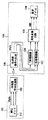
図3は本発明の実施の形態3による信号伝達システムの構成の概略を示すブロック図である。
【0033】
図3において、301はデジタル放送受信などを行うSTBであり、映像信号を出力する。302はSTB301より受信した映像信号を表示するテレビモニタである。なお、STB301とテレビモニタ302の間には、I2Cの双方向通信が可能になっているものとする。
【0034】
図4はSTB301及びテレビモニタ302を詳細に説明するためのブロック図であり、図において図3と同一または相当する構成要素については同じ符号を用い、その説明を省略する。
【0035】
図4において、402はMPEGデコーダであり、デジタル放送などの受信を行い映像のベースバンド信号を出力する。403は映像出力インターフェースであり、MPEGデコーダ402より出力された映像信号を出力する。404はCPUであり、プログラムROM405によって動作し、MPEGデコーダ402及びその周辺を制御する。また、CPU404はI2Cコントローラ406も制御可能である。408は映像入力インターフェースであり、伝送路を介して受信した映像信号を入力する。409はデバイスインターフェースであり、表示のための表示デバイスに適した信号に変換する。410はLCDやCRTなどのディスプレイデバイスそのものを表している。411はI2Cコントローラであり、I2Cバスをコントロールするものであり、内部にテレビモニタ302の性能に関する情報を格納するROMテーブル412を有する。なお、ROMテーブル412には、ディスプレイデバイス410から出力可能な映像の解像度に関する情報、ディスプレイデバイス410から出力可能な音声のチャンネル数に関する情報、輝度信号及び色差信号をRGB信号に変換する信号変換方法に関する情報、映像信号のガンマ補正に関する情報、テレビモニタ302が映像をエンハンス加工処理しないモードを有するか否かに関する情報、テレビモニタ302のメーカーコード及び機器コードに関する情報を含むものである。また、テレビモニタ302は、I2Cコントローラ411を介して、現在どのようなアスペクト変換処理をして映像出力しているかをSTB301へ出力するものとする。
【0036】
以上のように構成された信号伝達システムの動作について図5を説明する。ここでは、I2Cによる初期プロトコルについて図5を用いて説明する。
まず、最初にSTB301側がテレビモニタ302に対してテレビモニタ302のメーカーコード及び機器コードをたずねる(S1)。テレビモニタ302はROMテーブル412からメーカーコード及び機器コードをSTB側301に返信する(S2)。
【0037】
STB301は受信したメーカーコード及び機器コードが既知のものであれば、プロトコルを終了する(S3)。また、STB301は、受信したメーカーコード及び機器コードが既知でない場合は、テレビモニタ302がどのような走査速度に対応しているかをたずねる(S4)。テレビモニタ302は自身が走査可能なスキャンのレートについて回答する(S5)。
【0038】
次に、STB301側からテレビモニタ302側がどのような音の再生ができるかをたずねる(S6)。テレビモニタ302側は自身が出力可能な音のチャンネル数を返信する(S7)。これにより、STB301とテレビモニタ302の間で初期のプロトコルは終了する。
【0039】
次に、ケース1として、STB301が480iのLR2チャンネルの音声を有する放送を受信した場合を仮定する。この場合、先程の初期アクセスのネゴシエーションによって、STB301は、テレビモニタ302が480i及び2チャンネルのLRを出力できることがわかっているので、表示レートや音声の加工なしにそのままテレビモニタ302側に出力を行う。
また、別の場合でケース2として、放送受信が1080iの5.1チャンネル放送であった場合には、STB301は、1080iは、接続されているテレビモニタ302では、受像できないことが初期のプロトコルネゴシエーションによってわかっているので、STB301側で1080iから480pの変換を行う。480pへの変換を行うのは先のネゴシエーションでテレビモニタ302が480pまでの表示レートが可能であることがわかっていることによる。また、オーディオも5.1チャンネルの再生は、接続されているテレビモニタではできないことがわかっているので、2チャンネルのLRにダウンミックスするという処理をSTB301側で行うことによって、結果的に映像データは480pの出力を、音声データはLRのダウンミックス2チャンネルを出力する。
【0040】
ここで、テレビモニタ302の中にもつI2Cコントローラ411の内部にあるROMテーブル412について図7を用いて説明する。例えば、アドレスの01番地には表示可能レートを表わす4ビットを格納しておき、例えば480iの299.7Hzの信号を表示可能であるテレビモニタであれば、0000という値が入っているものとする。また、アドレスの02番地には出音可能なチャンネル数が格納されており、6チャンネルデコードできるものであれば、0006などの値が入っているものとする。このようなコードは業界でアドレスとその数値を標準で決めておくことによって、もしテレビモニタ側がSTBにとって既知でないメーカーであっても、最低限のプロトコルが決まっていることで、映像が映らない、もしくは、正常でないアスペクトで映ることや、音がならないなどという事態は回避することができる。つまり、従来のように、送信側が、PCモニタ側やテレビモニタ側で引き込めないフレームレートなどで伝送し、映像表示ができないといった問題を回避することができる。
【0041】
このように本実施の形態3による信号伝達システムでは、STBはテレビモニタの性能を知った上で出力するので、従来はテレビモニタ側でスキャンできないレートをSTBが出す可能性があったが、このようなネゴシエーションを行っておくことによって、テレビモニタ側で映像が映らない、もしくは音がならない等の問題を回避することができる。
【0042】
また、テレビモニタがメーカーコードと機器コードをSTBに送信する場合、そのメーカー及び機器コードがSTBとテレビモニタ間の両者間で情報が開示されているメーカー間であれば、例えば画像のアップコンバートをSTBがすべきか、テレビモニタ側にまかせるべきかをそれぞれの持っているアップコンバートの性能比較でよいほうを自動的に選ぶことができる。
【0043】
また、初期アクセスの例として、先程はスキャンタイプと何チャンネルの音が再生できるかだけをネゴシエーションとして行う例を挙げたが、その他に接続しているテレビモニタが16対9のワイドテレビか4対3のノーマルのテレビかがわかれば、自動的にSTBの側でレターボックス変換またはパンスキャン変換を行い出力することで、正しいアスペクトを自動的に得ることができる。従って、従来のように、STB側の初期メニューで被接続モニタがワイドであるかノーマルであるかを設定する必要がなくなる。
【0044】
また、テレビモニタは一般に受信した信号をそのまま出力するのではなく、その中で特に輝度や色についてエンハンスして出力を行う。しかし、パソコンなどのユーザでは、故意に輝度や色を操作することは望ましくない場合があるので、テレビモニタ側のエンハンスの特性をSTB側に通知し、STB側でそのエンハンスの逆補正をかけたものを予め出力するようにすれば、トータルとしてテレビモニタ側にエンハンスされない映像信号を出力することができる。
【0045】
また、テレビモニタ側にエンハンスしないモードを設けるようにすれば、STB側からそのモードに強制的に切り換えて、色のエンハンスのない再現を確保することができる。
【0046】
また、次に被接続モニタがワイドテレビの場合、テレビ側にワイドモードやノーマルモードなどの表示モードがあるのが一般的で、例えば16対9のモニタがつながっている場合には、STBで受信した素材が16対9であるならば、STBはそのままアスペクト変換せず出力するが、テレビ側の設定がノーマル表示になっていると、図6の右側に示すように、本当は真円のものが縦長に映るようなことになってしまうことがあり得る。この場合には、STB側からテレビ側をフルの表示モードに設定するようにすれば、正常なアスペクト画を得ることができる。なお、図6は、左側の絵が本来期待される出力の16対9の絵であり、右側が誤ってテレビ側の設定がノーマルになった場合の誤ったアスペクトの図を表している。
【0047】
また、STBとテレビモニタの間をRGB信号ではなくY色差信号、つまりYPBPRなどの信号で伝送する場合には、元のRGB信号にテレビ側で変換するための変換式が異なる場合があるので、その変換式そのものを送信することも可能である。MPEGストリームデータの中にその変換式は記述されているので、STB側で抜き出したその変換式をI2Cを介してテレビモニタ側に送信することで、テレビモニタ側で正しいRGBに変換できる。
【0048】
なお、実施の形態3の信号伝達システムにおけるデータ送信は、図12に示すように映像信号線のCTL0もしくはCTL1を用いて多重して送付するようにしてもよい。
【0049】
実施の形態4.
以下に、本発明の実施の形態4による信号伝達システムについて図8から図16を用いて説明する。
【0050】
図12は、本発明の実施の形態4による信号伝達システムの送信側の映像出力インターフェースが具備するセレクタの構成を示した図である。なお、実施の形態3との違いは、映像出力インターフェース403がセレクタを備えた構成となっている点である。
【0051】
図12において、選択器(セレクタ)1201は、レッド色信号Rと、その他の制御信号であるCTL0をDEによって時間的に選択する。セレクタ1202は、グリーン信号Gとコントロール信号CTL1を時間的に選択する。セレクタ1203は、ブルー信号BとHVシンク信号を時間的に切り換える。ここで、DEとは画像の走査期間と帰線期間を区別する信号である。
【0052】
図10はセレクタの動作について説明するための図である。ここでは、セレクタ1201について説明するが、他のセレクタ1202,1203も同様に動作するものであり、その説明は省略する。図において、DE信号は映像期間の間はHIGHの期間であり、帰線期間の間はLOWの信号となる。
【0053】
セレクタ1201は、R信号及びCTL0信号が入力されるのにつれて、DE信号がHIGHレベルのときにはR信号を通過させ、DE信号がLOWの期間にはCTL0の信号を通過させるように動作する。これにより、出力信号は、映像期間にはR信号が入り、帰線期間にはCTL0の信号、つまり制御データを送信することが可能なる。なお、この帰線期間は出力のビデオレートがインターレースの場合、図8の左側に示すような帰線期間の状態となり、プログレッシブの場合、図8の右側に示すような図となる。
【0054】
以上のように構成された信号伝達システムの動作について図9を用いて説明する。
まず、最初にSTBからテレビ側へメーカーコード及び機器コードの問い合わせを行う(S12)。テレビモニタ側が規格化の以前に出荷されたような機器である場合には、メーカーコード及び機器コードの問い合わせをしても、それに対する回答が得られないのが通常であるから、この場合には処理は終了し、STBの理解としては被接続モニタはI2Cへのテレビモニタ制御の機能をサポートしないので、今後I2Cで制御コマンドは送らないということに決定する(S13)。
【0055】
また、メーカーコード,機器コードの問い合わせの結果、返事があった場合には、それがSTBが既知のタイプかどうかを判定する(S14)。その場合、既知のタイプであった場合には処理は終了し、被接続モニタはSTB側でその性能が全てわかっているので、STB自身との組合せで最適な映像及び音声の出力を変えられるように動作をする(S15)。S14において、既知でないタイプ(UNKNOWN_TYPE)であると検出された場合には、ディスプレイが表示できるレートや音声チャンネル数を順に確認していく。音量調整やミュート,輝度,コントラスト調整などの基本的な調整機能は、業界標準を作成しておき、これらを使うことができるというようにSTBは判断する。
【0056】
図11は制御データの構成例であり、例えば01が2バイト期間連続するような予約パターンをヘッダとして持ち、次にSTBからテレビへのライトなのかテレビ側の状態をリードするためのリードなのかを識別するための何バイトかのR/Wデータ、そしてその次にテレビ側の何番地に何を書くかのアドレス、及びその書く値もしくは読んでくる値のデータの値をもって1つの制御データを構成する。制御データをこのような構成とすることにより、テレビ側に対して所望のコマンドを送ることができる。
【0057】
図13は受信側つまりテレビモニタの構成を示すブロック図である。
図13において、1301は受信用テレビモニタそのものを表す。1302は映像入力インターフェースであり、伝送路を介して受信した映像信号を入力する。1303は制御データ分離部であり、映像信号の中から制御データのみを分離する。1304は一時記憶部であり、制御データを一時的に記憶する。1305は画質制御部であり、映像信号の画質補正を行う。1306はデバイスインターフェースであり、ディスプレイデバイス1307に対してのインターフェースとなる。1308はCPUであり、制御データ分離部1303からの制御信号のうち、リアルタイム性を必要としないものについて、画質制御部1305を制御するのに使われる。1309はI2Cコントローラであり、I2Cバスを制御する。1310はI2Cコントローラ1309内のROMテーブルであり、テレビモニタ1301の性能について記述されている。輝度やコントラスト,音量など基本的なコマンドは業界で規格化されていることを前提として、そのような制御データの解釈はCPU1308が行い、CPU1308が画質制御部1305をコントロールするものとする。
【0058】
また、各フレーム毎に付随したデータは、CPU1308の介在なしに画質制御部1305に入力されることが望ましいため、直接画質制御部1305への制御信号も制御データ分離部1303が出力するものとする。制御信号の例としては、デコードされた画像がIピクチャ,Pピクチャ,Bピクチャのいずれであるかや、各フレーム毎のその素材が、プログレッシブで撮像されたものかインターレースで撮像されたものかなどの別を表す情報である。
【0059】
受信側をこのような構成とすることにより、輝度やコントラスト,音量など必要最低限のものをSTBからの制御としてテレビモニタ側を動作させることができ、また、フレーム毎に制御信号を伝送し、STBはフレーム毎に画質制御を行うことができる。
【0060】
図14は各フレーム毎に送る制御信号の例を示す図であり、ここでは、テレシネの情報を重畳する例を説明している。テレシネの画像の場合、フィールドリピートして出力したフィールドが存在し、従来は受信側でフィールドメモリを持ち、それの差分をとることでフィールドリピートしたものであるかどうかを検出して走査変換を行っていた。
【0061】
図15は従来の24pのテレシネ素材から例えば60pに変換する場合の変換回路を示すブロック図である。図15において、1501,1502,1503はそれぞれ1フィールドだけ遅延して出力するフィールドメモリを表す。相関計算手段1504はこれらフィールドメモリによって遅延して受信した信号と現在の信号との間の相関を画素ごとにとり、相関が有る場合には現在のフィールドはフィールドリピートされたものであるという判断をし、それぞれのフィールドメモリからフィールドメモリのどの出力を出力するかを選択する選択手段1505を制御するように動作する。このような従来のフィールドリピートの検出手段では、相関計算は検出精度を上げようとすると計算量が非常に煩雑になり、ハードが重くなるという欠点があり、また、非常によく似た図柄の場合、誤検出を避けられないという問題点があった。
【0062】
そこで、上記問題点を解決するために、本実施の形態では、図16に示すように、フィールドリピートの信号の伝送の方式を用いるようにした。
図16において、1601は放送波をデコードしベースバンドのビデオ信号の出力するMPEGデコーダであり、同時に放送波のストリーム中に含まれているそのフレームがトップフィールドかボトムフィールドかの情報、及びフィールドリピートされたものであるかどうかの情報を出力する。1602は伝送路符号化回路であり、走査期間にはMPEGデコーダ1601から出力されるRGB信号を伝送路符号化し出力するが、帰線期間には先に述べた制御データの形によってトップ,ボトム情報及びフィールドリピート情報を重畳する。1603は伝送路復号化回路であり、伝送路を介して受信した信号を元のRGBに復号化して、そのRGB信号をY色差信号にマトリクス変換し出力する。1604,1605,1606は、それぞれ1フィールドだけ映像信号を遅延させるフィールドメモリである。1607は伝送路復号化回路1603の出力のうち、制御データに重畳されている情報を抜き出す帰線期間コード解析手段である。1608は制御期間コード解析手段1607の出力を受けて、どのフィールドメモリからの出力を出力するかを選択する選択手段である。
【0063】
このように構成することによって、帰線期間コード解析手段1608は、送信側で重畳されたトップボトム情報及びフィールドリピート情報を誤りなく再生することができるので、正しいフィールドリピート情報及びトップ,ボトム情報を用いてY出力信号を得ることができる。
【0064】
次に、このような手段を用いてテレビモニタ側で24pから60p変換し、出力する場合の出力画像について図14を用いて説明する。図14において、A1はフレームAの第1フィールドを表し、A2は同じフレームAの第2フィールドを表すものとする。テレビモニタ入力信号は、例えば時間的にA1,A2でもう一度フィールドリピートされたA1が来るような場合を想定する。その場合、テレビモニタの出力信号は、まず、A1とA2から構成される1つのフレームが出力され、次の時間には同じくA1とA2から作られたフレームが出力される。ここで、モニタへの入力信号の第3フィールド目が第1フィールドと同じA1であるというように、正しく検出された場合にはテレビモニタの出力信号の第3フレーム目もA1とA2から作られる正しい絵が合成されるが、この時誤検出があると、正しく再現されないという問題があった。今回の図16に示すような構成においては、放送局側で重畳されたMPEGストリーム情報のトップ,ボトム情報及びフィールドリピート情報によって、リピートフィールドであるかどうかの判断をしているので、テレビモニタへの出力信号が正しく再生されることになる。
【0065】
なお、本実施の形態4において、テレシネの情報であるフィールドリピート及びトップ,ボトム情報を重畳した場合の説明を行ったが、例えば、そのフレームがIピクチャであったかPピクチャであったかBピクチャであったか、という情報も同様にして重畳することができる。但し、Iピクチャというのはフレーム内コーディングされた画像であり、Pピクチャはフレーム間の差分を用いたもの、Bピクチャは双方向の差分を用いて符号化された画像である。これによって、ノイズ除去のパラメータ設定をフレーム毎に行うことができる。従来はベースバンドの映像信号は、それぞれのフレームがIピクチャ,Bピクチャ,Pピクチャのいずれであるかわからないので、ノイズ除去を適応的に行うことができなかった。
【0066】
また、別の例として、MPEGの圧縮率の情報を重畳することもできる。この場合、MPEGの圧縮率は、MPEGのエレメンタリーストリームのヘッダより何メガビット/セカンドのビデオストリームかを得ることができる。さらに、水平,垂直サイズ及びフレームレートも得ることができるので、それとビットレートの関係をテレビ側に通知することによって、ノイズ除去のパラメータの設定をすることができる。このようにすれば、従来のように、送信側でMPEGの圧縮率に関する情報が分からないため、適切な処理ができないといった問題を回避できる。
【0067】
さらに、別の例として、素材の撮像がプログレッシブなカメラによるものか、インターレースのカメラによるものかという情報もMPEGストリームのヘッダより知ることができるので、この情報を同様の制御データとして送信することができる。そして、このデータによって、テレビモニタ側ではIP変換の、つまり、インターレースからプログレッシブへの変換の方法の選択に生かすことができる。従って、従来は、正確なIP変換を行うために動き検出回路が必要であり、その動き検出回路を用いて静止領域はプログレッシブな内挿を行い、動画領域はインターレースとして内挿していたが、ここではそれが不要になる。また、素材がインターレースであっても、画面の大部分にOSDなどのグラフィックス層をのせている場合も、プログレッシブで内挿することが適当であるが、OSDなどがのっているかどうかはSTB内部でわかっているので、その時にはプログレッシブとして制御信号を送信することによって、正しい内挿を行うことが可能となる。
【0068】
また、実施の形態4による信号伝達システムのデータ送信において、転送レートが遅いものは、図4に示すI2Cバスを利用してデータを送付するようにしてもよい。
【0069】
なお、上記実施の形態2において、色差信号を1本に多重したことによって、実施の形態1では3本の信号線が必要であったのが、2本の伝送路で映像信号全てを送信することが可能となったので、残りの1本の信号線を用いてMPEGデコーダから出力される自然画とOSDの領域を区別する信号を伝送することができる。この信号を伝送することによって、480pを放送時のIP変換のエラーが発生しても、480pのデータ放送に影響を及ぼさず、高画質に表示することができる。また、文字と自然画の処理の切りわけを画素ごとに行うことができるという特徴を有する。
また、上記実施の形態2においては伝送路が2本ですむため、残りの1本をユーザ定義の信号線として定義することができる。
【0070】
なお、図4では映像信号を出力する装置がSTBの場合について述べたが、省電力が要求されるようなデジタルカメラやノートPCの場合にも全く同様の構成が適用できる。デジタルカメラやノートPC等の携帯端末等の場合には、静止画を伝送するのでテレビモニタ側の映像入力インターフェース408もしくは、例えば、テレビモニタ本体の画質制御部1305に持っているメモリを持っている場合には、最初に11CバスコントロールもしくはCTL0もしくはCTL1を用いた制御でメモリの有無や容量を確認し、次に上記メモリに記憶することをテレビモニタ側にコントロール側(携帯端末側)が指示し、次にコントロール側(携帯端末側)は1枚もしくはテレビモニタ側のメモリ容量内の枚数をユーザの指示で映像出力インターフェース403を通じてテレビモニタ側に送る。テレビモニタ側は映像入力インターフェース408、もしくは例えばテレビモニタ本体の画質制御部1305にユーザの設定した映像を貯える。最初のメモリ有無の確認でテレビモニタ側がメモリを有さない場合は、動画と同様に常に映像信号を出力する。また、PC等の場合は内部の映像が変わる度に同様の制御を行うためにPCの映像に変化が生じると上記シーケンスで静止データを送信するものを含む。こうする事によりデジタルカメラやノートPC等の携帯端末から連続的に同じ静止画を再送することなくテレビモニタ側に保持された静止画をテレビモニタ側に表示し続ける事ができる。これにより、映像信号の発生側のデジタルカメラなどの映像出力インターフェースは1枚の静止画を伝送する場合にのみ動作すればよく、省電力化につながるという効果を有する。なお、この静止画伝送を時間的に繰り返すことによって、例えば1秒おきに静止画を送ったり、休んだりすることを繰り返すことによって、モーションJPEGのような画像を高効率に省電力で伝送することも可能になる。
【0071】
【発明の効果】
本発明の伝送システムによれば、映像信号の送信側,及び受信側のハードウエアの構成を簡単なものとできる信号伝達システムを実現可能である。
【0073】
また、送信装置が信号受信装置の性能を予め知ることができ、従来のように信号受信装置側でスキャンできないレートを送信することなく、信号受信装置の性能に基づいて信号伝送するので、信号受信装置側で映像が映らなかったり、音声がならないなどの問題を回避できる。
【0081】
また、現在出力されている映像フレーム信号がMPEGデコーダ内で繰り返し出力により生成されたものであるか否かを示す制御情報を、映像信号の垂直帰線期間に多重して出力することより、必要最低限の制御情報に基づいて信号受信装置を動作させることができる。
【0082】
さらに、伝送システムの制御情報が、MPEG規格のピクチャエンコード方式を表すI,P,Bピクチャを区分可能な情報であることより、ノイズを除去するためのパラメータ設定をフレーム毎に行うことができる伝送システムを実現可能である。
【0083】
さらに、伝送システムの制御情報が、MPEG規格の圧縮率情報であることより、ノイズを除去するためのパラメータ設定をフレーム毎に行うことができる伝送システムを実現可能である。
【0084】
さらに、伝送システムの制御情報が、MPEG符号化する前の素材がプログレッシブスキャンで撮像されたものかインタレーススキャンで撮像されたものかを表す情報であることより、信号受信装置はインターレースからプログレッシブへの変換方法を選択することができる。
【図面の簡単な説明】
【図1】実施の形態1による信号伝達システムの構成を示すブロック図である
【図2】実施の形態2による信号伝達システムの構成を示すブロック図である。
【図3】実施の形態3による信号伝達システムの概略構成図である。
【図4】実施の形態3による信号伝達システムの詳細な構成を示すブロック図である。
【図5】実施の形態3による信号伝達システムにおける初期プロトコルを説明するための図である。
【図6】16対9のワイド素材であるテレビの画面表示の様子を示す図である。
【図7】ROMテーブルの一例を示す図である。
【図8】出力ビデオレートがインターレースの場合とプログレッシブの場合のそれぞれに帰線期間を説明するための図である。
【図9】本発明の実施の形態4による信号伝達システムの動作を説明するためのフローチャート図である。
【図10】セレクタの動作を説明するための図である。
【図11】制御データの構成例を示す図である。
【図12】実施の形態4による信号伝達システムにおけるセレクタの構成を示す図である。
【図13】実施の形態4による信号伝達システムの受信側の構成を示すブロック図である。
【図14】実施の形態4による信号伝達システムにおいて各フレーム毎に送る制御信号の一例を示す図である。
【図15】従来の24pのテレシネ素材から例えば60pに変換する場合の変換回路を示すブロック図である。
【図16】実施の形態4におけるフィールドリピートの信号の伝送の方式を示す図である。
【図17】従来の信号伝達システムの構成を示すブロック図である。
【符号の説明】
101,201 映像信号出力装置
102,202 MPEGデコーダ
103,204 伝送路符号化回路
104,205 表示装置
105,206 伝送路復号化回路
106,208 Y処理回路
107,209 色処理回路
108,210 信号変換回路
109,211 表示デバイス
203 時分割多重回路
207 分離回路
301 STB
302,1301 TVモニタ
402 MPEGデコーダ
403 映像出力インターフェース
404 CPU
405 プログラムROM
406 I2Cコントローラ
408,1302 映像入力インターフェース
409,1306 デバイスインターフェース
410,1307 ディスプレイデバイス
411,1309 I2Cコントローラ
412,1309 ROMテーブル
1201,1202,1203 セレクタ
1303 制御データ分離部
1304 一時記憶部
1305 画質制御部
1308 CPU[0001]
TECHNICAL FIELD OF THE INVENTION
The present invention relates to a signal transmission system for transmitting an image signal, and more particularly to a signal transmission system capable of simplifying a hardware configuration of a transmission side and a reception side of a video signal.
[0002]
[Prior art]
A conventional example will be described with reference to FIG. FIG. 17 is a block diagram illustrating a configuration of a conventional signal transmission system.
In FIG. 17,
[0003]
The operation of the signal transmission system configured as described above will be described.
The
[0004]
On the other hand, on the
[0005]
[Problems to be solved by the invention]
However, in the above-described conventional signal transmission system, since the transmission path encoding is performed using RGB signals, the output of the MPEG decoder is once converted into RGB signals, encoded and transmitted, and transmitted on the transmission path. In order to perform signal processing again, the RGB signal is converted to YPBPRIn order to output the RGB signals to the last display device as RGB signals, it is necessary to convert the Y color difference signals into RGB signals again, which has a disadvantage that much hardware is required. Was.
[0006]
SUMMARY OF THE INVENTION The present invention has been made in order to solve the above problems, and has as its object to provide a signal transmission system capable of simplifying hardware configurations of a video signal transmitting side and a video signal receiving side.
[0007]
[Means for Solving the Problems]
In order to solve the above problems,A transmission system according to a first aspect of the present invention is a transmission system for digitally transmitting a video signal via a transmission path, wherein a compression-encoded signal is compressed and decoded, and a baseband luminance signal, a color difference signal, and the compression-encoded signal are transmitted. Compression decoding means for outputting a control signal used for controlling the image quality included in the image signal, the luminance signal and the chrominance signal are in a video period, the control signal is time-division multiplexed in a retrace period and transmitted to the transmission line. Channel coding means for coding into a suitable channel coded signal and I2C ( Inter IC control A) an I2C controller for outputting a signal; and a CPU for controlling the I2C controller and the compression / decoding means. The compression / decoding means is provided to the receiving device by the CPU based on the receiving device information received via the I2C controller. A transmission device controlled to perform output that can be displayed in, a transmission line decoding unit that decodes the transmission line encoded signal into the luminance signal, the color difference signal, and the control signal, and the reception device information. A ROM table to be stored, an I2C controller that outputs the receiving device information stored in the ROM table to the transmitting device according to the I2C signal output from the transmitting device, and the luminance signal and the luminance signal based on the control signal. And a picture quality control means for controlling the picture quality of the color difference signal.
This makes it possible to simplify the hardware configuration of the transmitting side and the receiving side of the video signal.transmissionThe system is feasible.
[0009]
Also,Since the transmitting device can know the performance of the signal receiving device in advance and transmit the signal based on the performance of the signal receiving device without transmitting a rate that cannot be scanned by the signal receiving device as in the related art, the signal receiving device side Can avoid problems such as no video or no sound.
[0017]
Also,Control information indicating whether or not the currently output video frame signal is generated by repeated output in the MPEG decoder.,Output multiplexed during vertical blanking interval of image signalByBased on the minimum required control informationReceiverCan be operated.
[0018]
In addition, transmissionsystemofControl informationButThat can classify I, P, and B pictures representing picture encoding schemes of the MPEG standardBeingWith this, parameters for removing noise can be set for each frame.transmissionThe system is feasible.
[0019]
Further transmissionsystemofControl informationBut, MPEG standard compression rate informationBeingWith this, parameters for removing noise can be set for each frame.transmissionThe system is feasible.
[0020]
In addition, transmissionsystemofControl informationBut, Information indicating whether the material before MPEG encoding was captured by progressive scan or interlaced scanByThe signal receiving device can select a conversion method from interlace to progressive.
[0021]
BEST MODE FOR CARRYING OUT THE INVENTION
Hereinafter, embodiments of the present invention will be described with reference to the drawings. The embodiment described here is merely an example, and the present invention is not necessarily limited to this embodiment.
[0022]
Hereinafter, a signal transmission system according to
FIG. 1 is a block diagram showing a configuration of a signal transmission system according to
[0023]
In FIG. 1,
[0024]
The operation of the signal transmission system configured as described above will be described.
The
[0025]
The transmission
[0026]
In such a signal transmission system according to the first embodiment, since the Y color difference signal output from the
[0027]
Hereinafter, a signal transmission system according to a second embodiment of the present invention will be described with reference to FIG.
FIG. 2 is a block diagram showing a configuration of a signal transmission system according to
[0028]
In FIG. 2,
[0029]
The operation of the signal transmission system configured as described above will be described.
The
[0030]
The transmission
[0031]
The signal transmission system according to the second embodiment includes the time
[0032]
Hereinafter, a signal transmission system according to a third embodiment of the present invention will be described with reference to FIGS.
FIG. 3 is a block diagram schematically showing a configuration of a signal transmission system according to
[0033]
In FIG. 3,
[0034]
FIG. 4 is a block diagram for describing the
[0035]
In FIG. 4,
[0036]
FIG. 5 illustrates the operation of the signal transmission system configured as described above. Here, I2The initial protocol by C will be described with reference to FIG.
First, the
[0037]
If the received maker code and device code are known, the
[0038]
Next, the
[0039]
Next, as a
In another
[0040]
Here, the I in the
[0041]
As described above, in the signal transmission system according to the third embodiment, since the STB is output after knowing the performance of the TV monitor, conventionally, the STB may output a rate that cannot be scanned by the TV monitor. By performing such negotiation, it is possible to avoid problems such as no video or no sound on the television monitor.
[0042]
When the TV monitor transmits the maker code and the device code to the STB, if the maker and the device code are between manufacturers whose information is disclosed between the STB and the TV monitor, for example, the image up-conversion is performed. Whether the STB should be performed or the TV monitor should be left can be automatically selected by comparing the up-conversion performance of each device.
[0043]
Also, as an example of the initial access, an example in which only the scan type and how many channels of sound can be reproduced is negotiated earlier, but the other connected TV monitor is a 16: 9 wide TV or a 4 TV monitor. If it is determined that the television is a normal television of No. 3, the correct aspect can be automatically obtained by automatically performing letter box conversion or pan scan conversion on the STB side and outputting. Therefore, it is not necessary to set whether the connected monitor is wide or normal in the initial menu on the STB side as in the related art.
[0044]
In general, a television monitor does not output a received signal as it is, but outputs the signal with enhanced brightness and color among them. However, there is a case where it is not desirable for a user such as a personal computer to intentionally manipulate the luminance and the color. Therefore, the enhancement characteristics of the television monitor are notified to the STB side, and the enhancement is inversely corrected on the STB side. By outputting the video signal in advance, it is possible to output a video signal which is not enhanced to the TV monitor side as a total.
[0045]
In addition, if a mode that does not enhance is provided on the television monitor side, the mode can be forcibly switched from the STB side to that mode, and reproduction without color enhancement can be ensured.
[0046]
Next, when the connected monitor is a wide-screen TV, the TV generally has a display mode such as a wide mode or a normal mode. For example, when a 16-to-9 monitor is connected, the reception mode is STB. If the material obtained is 16: 9, the STB is output without performing the aspect conversion as it is, but if the setting on the TV side is set to the normal display, as shown on the right side of FIG. It may happen that the image is displayed vertically. In this case, a normal aspect image can be obtained by setting the TV side to the full display mode from the STB side. FIG. 6 is a 16: 9 picture of the originally expected output on the left side, and the right side shows an incorrect aspect when the setting on the TV side is erroneously set to normal.
[0047]
Also, a Y color difference signal, that is, a YPBPRIn the case of transmission using such a signal, since the conversion formula for converting the original RGB signal on the television side may be different, the conversion formula itself can be transmitted. Since the conversion formula is described in the MPEG stream data, the conversion formula extracted on the STB side is expressed as I2By transmitting the data to the TV monitor via C, the TV monitor can convert the data into correct RGB.
[0048]
The data transmission in the signal transmission system according to the third embodiment may be multiplexed and transmitted using CTL0 or CTL1 of the video signal line as shown in FIG.
[0049]
Hereinafter, a signal transmission system according to the fourth embodiment of the present invention will be described with reference to FIGS.
[0050]
FIG. 12 is a diagram illustrating a configuration of a selector included in a video output interface on a transmission side of a signal transmission system according to a fourth embodiment of the present invention. The difference from the third embodiment is that the
[0051]
In FIG. 12, a selector (selector) 1201 temporally selects a red signal R and CTL0, which is another control signal, by DE. The
[0052]
FIG. 10 is a diagram for explaining the operation of the selector. Here, the
[0053]
As the R signal and the CTL0 signal are input, the
[0054]
The operation of the signal transmission system configured as described above will be described with reference to FIG.
First, the STB inquires the TV side about the maker code and the device code (S12). If the TV monitor is a device that was shipped before the standardization, it is usually impossible to obtain an answer to the inquiry about the manufacturer code and device code. The process ends, and the STB understands that the connected monitor is I2C does not support TV monitor control function.2At C, it is determined that no control command is sent (S13).
[0055]
If there is a reply as a result of the inquiry about the maker code and the device code, it is determined whether the reply is of a known type of the STB (S14). In this case, if the type is a known type, the process ends, and the connected monitor knows all its performance on the STB side, so that the optimal video and audio output can be changed in combination with the STB itself. (S15). If it is detected in S14 that the type is unknown (UNKNOWN_TYPE), the rate at which the display can be displayed and the number of audio channels are sequentially checked. The STB determines that basic adjustment functions such as volume adjustment, mute, brightness, and contrast adjustment have been prepared for industry standards and can be used.
[0056]
FIG. 11 shows an example of the structure of control data. For example, 01 has a reserved pattern that continues for 2 bytes as a header, and then is it a write from the STB to the TV or a read to read the state of the TV? One piece of control data is composed of several bytes of R / W data for identifying the data, and then the address of what address to write on the television side, and the value of the data to be written or read. Constitute. With such a configuration of the control data, a desired command can be transmitted to the television.
[0057]
FIG. 13 is a block diagram showing a configuration of a receiving side, that is, a television monitor.
In FIG. 13,
[0058]
Since it is desirable that data accompanying each frame be input to the image
[0059]
By adopting such a configuration on the receiving side, it is possible to operate the television monitor side as control from the STB with the minimum necessary such as brightness, contrast, and volume, and to transmit a control signal for each frame, The STB can control image quality for each frame.
[0060]
FIG. 14 is a diagram illustrating an example of a control signal transmitted for each frame. Here, an example in which telecine information is superimposed will be described. In the case of a telecine image, there is a field that has been output by field repeat.Conventionally, the receiving side has a field memory, and by taking the difference between the two, it detects whether it is a field repeat and performs scan conversion. I was
[0061]
FIG. 15 is a block diagram showing a conversion circuit for converting a conventional 24p telecine material to, for example, 60p. In FIG. 15,
[0062]
Therefore, in order to solve the above problem, in the present embodiment, as shown in FIG. 16, a method of transmitting a field repeat signal is used.
In FIG. 16,
[0063]
With this configuration, the blanking period
[0064]
Next, an output image in the case of converting from 24p to 60p on the television monitor side using such means and outputting the converted image will be described with reference to FIG. In FIG. 14, A1 represents the first field of the frame A, and A2 represents the second field of the same frame A. It is assumed that the television monitor input signal is, for example, A1 which is temporally repeated once again at A1 and A2. In this case, as the output signal of the television monitor, first, one frame composed of A1 and A2 is output, and the next time, a frame made of A1 and A2 is also output. Here, if the third field of the input signal to the monitor is correctly detected such that the third field of the input signal to the monitor is the same A1 as the first field, the third frame of the output signal of the television monitor is also formed from A1 and A2. Although a correct picture is synthesized, there is a problem that if there is an erroneous detection at this time, the picture is not correctly reproduced. In the configuration shown in FIG. 16 this time, whether or not a field is a repeat field is determined on the basis of the top and bottom information and field repeat information of the MPEG stream information superimposed on the broadcast station side. Will be reproduced correctly.
[0065]
In the fourth embodiment, the description has been given of the case where the field repeat and the top / bottom information, which are telecine information, are superimposed. For example, whether the frame is an I picture, a P picture, or a B picture, Can be similarly superimposed. However, an I picture is an image coded in a frame, a P picture is an image using a difference between frames, and a B picture is an image coded using a bidirectional difference. This makes it possible to set noise removal parameters for each frame. Conventionally, it has not been possible to adaptively remove noise from a baseband video signal because it is not known whether each frame is an I picture, a B picture, or a P picture.
[0066]
Further, as another example, information on the MPEG compression ratio can be superimposed. In this case, the compression ratio of MPEG can be obtained from the megabit / second video stream from the header of the MPEG elementary stream. Further, since the horizontal and vertical sizes and the frame rate can also be obtained, by notifying the relationship between the horizontal and vertical sizes and the bit rate to the television side, it is possible to set noise removal parameters. With this configuration, unlike the related art, since the information on the MPEG compression ratio cannot be known on the transmission side, it is possible to avoid a problem that appropriate processing cannot be performed.
[0067]
Further, as another example, since it is also possible to know from the header of the MPEG stream information on whether the material is captured by a progressive camera or an interlaced camera, it is possible to transmit this information as similar control data. it can. Then, this data can be used for the selection of the method of IP conversion, that is, the method of conversion from interlace to progressive on the television monitor side. Therefore, in the past, a motion detection circuit was required to perform accurate IP conversion, and a still area was progressively interpolated using the motion detection circuit, and a moving image area was interpolated as an interlace. Then it becomes unnecessary. Even if the material is interlaced, if a graphics layer such as an OSD is placed on the majority of the screen, it is appropriate to interpolate progressively. Since it is known internally, by transmitting the control signal as progressive at that time, correct interpolation can be performed.
[0068]
Further, in the data transmission of the signal transmission system according to the fourth embodiment, the data transmission with a slow transfer rate2Data may be sent using the C bus.
[0069]
In the second embodiment, since the color difference signals are multiplexed into one, three signal lines are required in the first embodiment, but all video signals are transmitted through two transmission paths. Therefore, it is possible to transmit a signal for distinguishing a natural image output from the MPEG decoder from an OSD area using the remaining one signal line. By transmitting this signal, even if an IP conversion error occurs during the broadcast of 480p, it does not affect the data broadcast of 480p, and the image can be displayed with high image quality. In addition, there is a feature that the processing of characters and natural images can be separated for each pixel.
Further, in the second embodiment, since only two transmission paths are required, the remaining one can be defined as a user-defined signal line.
[0070]
Although FIG. 4 illustrates the case where the device that outputs the video signal is the STB, the same configuration can be applied to a digital camera or a notebook PC that requires power saving. In the case of a portable terminal such as a digital camera or a notebook PC, since a still image is transmitted, the portable terminal has a
[0071]
【The invention's effect】
Transmission of the present inventionAccording to the system,It is possible to realize a signal transmission system that can simplify the hardware configuration of the image signal transmitting side and the image signal receiving side.
[0073]
Also,Since the transmitting device can know the performance of the signal receiving device in advance and transmit the signal based on the performance of the signal receiving device without transmitting a rate that cannot be scanned by the signal receiving device as in the related art, the signal receiving device side Can avoid problems such as no video or no sound.
[0081]
In addition,Video frame signal being outputIs MControl information indicating whether or not it is generated by repeated output in the PEG decoder,Output multiplexed during vertical blanking interval of image signalThan thatThe signal receiving device can be operated based on the minimum necessary control information.
[0082]
In addition, transmissionsystemofControl informationBut, P, and B pictures representing the picture encoding system of the MPEG standard can be classified, so that parameter setting for removing noise can be performed for each frame.transmissionThe system is feasible.
[0083]
In addition, transmissionsystemofControl informationBut, The compression ratio information of the MPEG standard allows the parameter setting for removing noise to be performed for each frame.transmissionThe system is feasible.
[0084]
In addition, transmissionsystemofControl informationButSince the information indicating whether the material before the MPEG encoding has been captured by the progressive scan or the interlace scan is information, the signal receiving apparatus can select a method of converting the interlace to the progressive. it can.
[Brief description of the drawings]
FIG. 1 is a block diagram illustrating a configuration of a signal transmission system according to a first embodiment.
FIG. 2 is a block diagram showing a configuration of a signal transmission system according to a second embodiment.
FIG. 3 is a schematic configuration diagram of a signal transmission system according to a third embodiment.
FIG. 4 is a block diagram showing a detailed configuration of a signal transmission system according to a third embodiment.
FIG. 5 is a diagram for explaining an initial protocol in a signal transmission system according to a third embodiment.
FIG. 6 is a diagram showing a state of a screen display of a television which is a 16: 9 wide material.
FIG. 7 is a diagram showing an example of a ROM table.
FIG. 8 is a diagram for explaining a retrace period in each of the case where the output video rate is interlaced and the case where the output video rate is progressive.
FIG. 9 is a flowchart for explaining the operation of the signal transmission system according to the fourth embodiment of the present invention.
FIG. 10 is a diagram for explaining the operation of the selector.
FIG. 11 is a diagram illustrating a configuration example of control data.
FIG. 12 is a diagram illustrating a configuration of a selector in a signal transmission system according to a fourth embodiment.
FIG. 13 is a block diagram showing a configuration on a receiving side of a signal transmission system according to a fourth embodiment.
FIG. 14 is a diagram illustrating an example of a control signal transmitted for each frame in the signal transmission system according to the fourth embodiment.
FIG. 15 is a block diagram showing a conversion circuit for converting a conventional 24p telecine material into, for example, 60p.
16 is a diagram illustrating a method of transmitting a field repeat signal according to
FIG. 17 is a block diagram illustrating a configuration of a conventional signal transmission system.
[Explanation of symbols]
101,201 Video signal output device
102,202 MPEG decoder
103, 204 transmission line coding circuit
104, 205 display device
105,206 transmission line decoding circuit
106,208 Y processing circuit
107,209 color processing circuit
108,210 signal conversion circuit
109, 211 Display device
203 time division multiplexing circuit
207 Separation circuit
301 STB
302,1301 TV monitor
402 MPEG decoder
403 Video output interface
404 CPU
405 Program ROM
406 I2C controller
408, 1302 Video input interface
409, 1306 Device interface
410, 1307 Display device
411,1309 I2C controller
412,1309 ROM table
1201, 1202, 1203 Selector
1303 Control data separation unit
1304 Temporary storage unit
1305 Image quality control unit
1308 CPU
Claims (22)
圧縮符号化信号を圧縮復号してベースバンドの輝度信号と色差信号と前記圧縮符号化信号に含まれる画質の制御に用いる制御信号とを出力する圧縮復号化手段と、Compression decoding means for compressing and decoding the compression coded signal and outputting a baseband luminance signal, a color difference signal, and a control signal used for controlling image quality included in the compression coded signal;
前記輝度信号と前記色差信号とは映像期間に、前記制御信号は帰線期間に時分割多重して前記伝送路に適した伝送路符号化信号に符号化する伝送路符号化手段と、The luminance signal and the color difference signal are in a video period, the control signal is time-division multiplexed in a retrace period, and is a transmission line encoding unit that encodes the transmission signal into a transmission line encoded signal suitable for the transmission line,
I2C(I2C ( Inter IC controlInter IC control )信号を出力するI2Cコントローラと、An I2C controller for outputting a signal;
前記I2Cコントローラと前記圧縮復号化手段とを制御するCPUとを備え、A CPU for controlling the I2C controller and the compression / decoding means;
前記圧縮復号化手段は前記I2Cコントローラを介して受信した受信装置情報に基づきCPUによって受信装置で表示可能な出力を行うように制御される送信装置と、A transmitting device controlled by the CPU to perform an output that can be displayed on the receiving device based on the receiving device information received via the I2C controller;
前記伝送路符号化信号から前記輝度信号と前記色差信号と前記制御信号とに復号する伝送路復号化手段と、Transmission path decoding means for decoding the luminance signal, the color difference signal, and the control signal from the transmission path encoded signal,
前記受信装置情報を格納するROMテーブルと、A ROM table for storing the receiving device information;
前記送信装置から出力される前記I2C信号に従い、前記ROMテーブルに格納された前記受信装置情報を前記送信装置へ出力するI2Cコントローラと、An I2C controller that outputs the receiving device information stored in the ROM table to the transmitting device according to the I2C signal output from the transmitting device;
前記制御信号に基づき前記輝度信号と前記色差信号の画質の制御を行う画質制御手段と、を備えた受信装置からなる伝送システム。A transmission system comprising: a reception device including: an image quality control unit configured to control image quality of the luminance signal and the color difference signal based on the control signal.
圧縮符号化信号を圧縮復号して音声信号とベースバンドの輝度信号と色差信号と前記圧縮符号化信号に含まれる画質の制御に用いる制御信号を出力する圧縮復号化手段と、Compression decoding means for compressing and decoding the compression coded signal and outputting a control signal used for controlling the image signal included in the audio signal, the baseband luminance signal, the color difference signal, and the compression coded signal,
前記輝度信号と前記色差信号とは映像期間に、前記制御信号は帰線期間に時分割多重して前記伝送路に適した伝送路符号化信号に符号化する伝送路符号化手段と、The luminance signal and the color difference signal are in a video period, the control signal is time-division multiplexed in a retrace period, and is a transmission line encoding unit that encodes the transmission signal into a transmission line encoded signal suitable for the transmission line,
I2C(I2C ( Inter IC controlInter IC control )信号を出力するI2Cコントローラと、An I2C controller for outputting a signal;
前記I2Cコントローラと前記圧縮復号化手段とを制御するCPUとを備え、A CPU for controlling the I2C controller and the compression / decoding means;
前記圧縮復号化手段は前記I2Cコントローラを介して受信した受信装置情報に基づきCPUによって受信装置で表示可能な出力を行うように制御される送信装置と、A transmitting device controlled by the CPU to perform an output that can be displayed on the receiving device based on the receiving device information received via the I2C controller;
前記伝送路符号化信号から前記音声信号と前記輝度信号と前記色差信号と前記制御信号とに復号する伝送路復号化手段と、Transmission line decoding means for decoding the audio signal, the luminance signal, the color difference signal, and the control signal from the transmission line encoded signal,
前記受信装置情報を格納するROMテーブルと、A ROM table for storing the receiving device information;
前記送信装置から出力される前記I2C信号に従い、前記ROMテーブルに格納された前記受信装置情報を前記送信装置へ出力するI2Cコントローラと、An I2C controller that outputs the receiving device information stored in the ROM table to the transmitting device according to the I2C signal output from the transmitting device;
前記制御信号に基づき前記輝度信号と前記色差信号の画質の制御を行う画質制御手段と、を備えた受信装置からなる伝送システム。A transmission system comprising: a reception device including: an image quality control unit configured to control image quality of the luminance signal and the color difference signal based on the control signal.
圧縮符号化信号を圧縮復号してベースバンドの輝度信号と色差信号と前記圧縮符号化信号に含まれる画質の制御に用いる制御信号とを出力する圧縮復号化手段と、Compression decoding means for compressing and decoding the compression coded signal and outputting a baseband luminance signal, a color difference signal, and a control signal used for controlling image quality included in the compression coded signal;
前記輝度信号と前記色差信号とは映像期間に、前記制御信号は帰線期間に時分割多重して前記伝送路に適した伝送路符号化信号に符号化する伝送路符号化手段と、The luminance signal and the color difference signal are in a video period, the control signal is time-division multiplexed in a retrace period, and is a transmission line encoding unit that encodes the transmission signal into a transmission line encoded signal suitable for the transmission line,
I2C(I2C ( Inter IC controlInter IC control )信号を出力するI2Cコントローラと、An I2C controller for outputting a signal;
前記I2Cコントローラと前記圧縮復号化手段とを制御するCPUとを備え、A CPU for controlling the I2C controller and the compression / decoding means;
前記圧縮復号化手段は前記I2Cコントローラを介して受信した受信装置情報に基づきCPUによって受信装置で表示可能な出力を行うように制御される送信装置。A transmitting device, wherein the compression / decoding means is controlled by the CPU based on the receiving device information received via the I2C controller so as to perform an output which can be displayed on the receiving device.
画質の制御に用いる制御信号は帰線期間に時分割多重して前記映像信号と共に前記伝送路に適して符号化された伝送路符号化信号から、輝度信号と色差信号と前記制御信号とに復号する伝送路復号化手段と、A control signal used for controlling image quality is time-division multiplexed during a retrace period and decoded together with the video signal from a transmission line coded signal suitable for the transmission line into a luminance signal, a color difference signal, and the control signal. Transmission path decoding means,
表示可能とするための性能を示す情報である受信装置情報を格納するROMテーブルと、送信装置から出力されるI2C(A ROM table for storing receiving device information, which is information indicating performance for enabling display, and an I2C ( Inter IC controlInter IC control )信号に従い、ROMテーブルに格納された前記受信装置情報を前記送信装置へ出力するI2Cコントローラと、An I2C controller that outputs the receiving device information stored in the ROM table to the transmitting device according to a signal;
前記制御信号に基づき前記輝度信号と前記色差信号の画質の制御を行う画質制御手段と、を備えた受信装置。A receiving unit comprising: an image quality control unit configured to control image quality of the luminance signal and the color difference signal based on the control signal.
圧縮符号化信号を圧縮復号して音声信号とベースバンドの輝度信号と色差信号と前記圧縮符号化信号に含まれる画質の制御に用いる制御信号を出力する圧縮復号化手段と、Compression decoding means for compressing and decoding the compression coded signal and outputting a control signal used for controlling the image signal included in the audio signal, the baseband luminance signal, the color difference signal, and the compression coded signal,
前記輝度信号と前記色差信号とは映像期間に、前記制御信号は帰線期間に時分割多重して前記伝送路に適した伝送路符号化信号に符号化する伝送路符号化手段と、The luminance signal and the color difference signal are in a video period, the control signal is time-division multiplexed in a retrace period, and is a transmission line encoding unit that encodes the transmission signal into a transmission line encoded signal suitable for the transmission line,
I2C(I2C ( Inter IC controlInter IC control )信号を出力するI2Cコントローラと、An I2C controller for outputting a signal;
前記I2Cコントローラと前記圧縮復号化手段とを制御するCPUとを備え、A CPU for controlling the I2C controller and the compression / decoding means;
前記圧縮復号化手段は前記I2Cコントローラを介して受信した受信装置情報に基づきCPUによって受信装置で表示可能な出力を行うように制御される送信装置。A transmitting device, wherein the compression / decoding means is controlled by the CPU based on the receiving device information received via the I2C controller so as to perform an output which can be displayed on the receiving device.
画質の制御に用いる制御信号は帰線期間に時分割多重して、前記映像信号と前記音声信号と共に前記伝送路に適して符号化された伝送路符号化信号から、前記音声信号と輝度信号と色差信号と前記制御信号とに復号する伝送路復号化手段と、The control signal used for controlling the image quality is time-division multiplexed during the retrace interval, and the audio signal and the luminance signal are obtained from a transmission path encoded signal that is encoded suitable for the transmission path together with the video signal and the audio signal. Transmission path decoding means for decoding into a color difference signal and the control signal,
表示可能とするための性能を示す情報である受信装置情報を格納するROMテーブルと、送信装置から出力されるI2C(A ROM table for storing receiving device information, which is information indicating performance for enabling display, and an I2C ( Inter IC controlInter IC control )信号に従い、前記ROMテーブルに格納された前記受信装置情報を前記送信装置へ出力するI2Cコントローラと、An I2C controller that outputs the receiving device information stored in the ROM table to the transmitting device according to a signal;
前記制御信号に基づき前記輝度信号と前記色差信号の画質の制御を行う画質制御手段とを備えた受信装置。A receiving device comprising image quality control means for controlling the image quality of the luminance signal and the color difference signal based on the control signal.
圧縮符号化信号を圧縮復号してベースバンドの輝度信号と色差信号と前記圧縮符号化信号に含まれる画質の制御に用いる制御信号とを出力する圧縮復号化ステップと、A compression decoding step of compressing and decoding the compression coded signal and outputting a baseband luminance signal, a color difference signal, and a control signal used for controlling image quality included in the compression coded signal;
前記輝度信号と前記色差信号とは映像期間に、前記制御信号は帰線期間に時分割多重して前記伝送路に適した伝送路符号化信号に符号化する伝送路符号化ステップと、The luminance signal and the chrominance signal are in a video period, the control signal is time-division multiplexed in a retrace period and is encoded in a transmission line encoding signal suitable for the transmission line,
I2C(I2C ( Inter IC controlInter IC control )信号を出力するI2Cコントロールステップと、I) an I2C control step for outputting a signal;
前記I2Cコントロールステップと前記圧縮復号化ステップとをCPUで制御するステップとを有し、Controlling the I2C control step and the compression / decoding step by a CPU;
前記圧縮復号化ステップは前記I2Cコントロールステップを介して受信した受信装置情報に基づきCPUによって受信装置で表示可能な出力を行うように制御される送信ステップとThe compression / decoding step is a transmission step in which the CPU controls the CPU to perform an output that can be displayed on the receiving device based on the receiving device information received through the I2C control step;
前記伝送路符号化信号から前記輝度信号と前記色差信号と前記制御信号とに復号する伝送路復号化ステップと、A transmission line decoding step of decoding the luminance signal, the color difference signal, and the control signal from the transmission line encoded signal,
前記受信装置情報をROMテーブルに格納する格納ステップと、Storing the receiving device information in a ROM table;
前記送信ステップから出力される前記I2C信号に従い、前記ROMテーブルに格納された前記受信装置情報を前記送信ステップへ出力するI2Cコントロールステップと、An I2C control step of outputting the receiving device information stored in the ROM table to the transmitting step according to the I2C signal output from the transmitting step;
前記制御信号に基づき前記輝度信号と前記色差信号の画質の制御を行う画質制御ステップと、を備えた受信ステップからなる伝送方法。An image quality control step of controlling the image quality of the luminance signal and the color difference signal based on the control signal.
圧縮符号化信号を圧縮復号して音声信号とベースバンドの輝度信号と色差信号と前記圧縮符号化信号に含まれる画質の制御に用いる制御信号を出力する圧縮復号化ステップと、A compression decoding step of compressing and decoding the compression coded signal and outputting a control signal used for controlling an audio signal, a baseband luminance signal, a color difference signal, and image quality included in the compression coded signal,
前記輝度信号と前記色差信号とは映像期間に、前記制御信号は帰線期間に時分割多重して前記伝送路に適した伝送路符号化信号に符号化する伝送路符号化ステップと、The luminance signal and the chrominance signal are in a video period, the control signal is time-division multiplexed in a retrace period and is encoded in a transmission line encoding signal suitable for the transmission line,
I2C(I2C ( Inter IC controlInter IC control )信号を出力するI2Cコントロールステップと、I) an I2C control step for outputting a signal;
前記I2Cコントロールステップと前記圧縮復号化ステップとをCPUで制御するステップとを有し、Controlling the I2C control step and the compression / decoding step by a CPU;
前記圧縮復号化ステップは前記I2Cコントロールステップを介して受信した受信装置情報に基づきCPUによって受信装置で表示可能な出力を行うように制御される送信ステップと、A transmitting step in which the compression / decoding step is controlled by the CPU based on the receiving apparatus information received through the I2C control step so as to perform an output that can be displayed on the receiving apparatus;
前記伝送路符号化信号から前記音声信号と前記輝度信号と前記色差信号と前記制御信号とに復号する伝送路復号化ステップと、A transmission line decoding step of decoding the audio signal, the luminance signal, the color difference signal, and the control signal from the transmission line encoded signal,
前記受信装置情報をROMテーブルに格納する格納ステップと、Storing the receiving device information in a ROM table;
前記送信ステップから出力される前記I2C信号に従い、前記ROMテーブルに格納された前記受信装置情報を前記送信装置へ出力するI2Cコントロールステップと、An I2C control step of outputting the receiving device information stored in the ROM table to the transmitting device according to the I2C signal output from the transmitting step;
前記制御信号に基づき前記輝度信号と前記色差信号の画質の制御を行う画質制御ステップと、を備えた受信ステップからなる伝送方法。An image quality control step of controlling the image quality of the luminance signal and the color difference signal based on the control signal.
圧縮符号化信号を圧縮復号してベースバンドの輝度信号と色差信号と前記圧縮符号化信号に含まれる画質の制御に用いる制御信号とを出力する圧縮復号化ステップと、A compression decoding step of compressing and decoding the compression coded signal and outputting a baseband luminance signal, a color difference signal, and a control signal used for controlling image quality included in the compression coded signal;
前記輝度信号と前記色差信号とは映像期間に、前記制御信号は帰線期間に時分割多重して前記伝送路に適した伝送路符号化信号に符号化する伝送路符号化ステップと、The luminance signal and the chrominance signal are in a video period, the control signal is time-division multiplexed in a retrace period and is encoded in a transmission line encoding signal suitable for the transmission line,
I2C(I2C ( Inter IC controlInter IC control )信号を出力するI2Cコントロールステップと、I) an I2C control step for outputting a signal;
前記I2Cコントロールステップと前記圧縮復号化ステップとをCPUで制御するステップとを有し、Controlling the I2C control step and the compression / decoding step by a CPU;
前記圧縮復号化ステップは前記I2Cコントロールステップを介して受信した受信装置情報に基づきCPUによって受信装置で表示可能な出力を行うように制御される送信方法。A transmitting method in which the compression / decoding step is controlled so as to perform an output which can be displayed on a receiving device by a CPU based on the receiving device information received via the I2C control step.
画質の制御に用いる制御信号は帰線期間に時分割多重して前記映像信号と共に前記伝送The control signal used for controlling the image quality is time-division multiplexed during the retrace period and transmitted together with the video signal 路に適して符号化された伝送路符号化信号から、輝度信号と色差信号と前記制御信号とに復号する伝送路復号化ステップと、A transmission line decoding step of decoding a transmission line encoded signal suitable for a channel into a luminance signal, a color difference signal, and the control signal,
表示可能とするための性能を示す情報である受信装置情報をROMテーブルに格納する格納ステップと、A storage step of storing reception device information, which is information indicating performance for enabling display, in a ROM table;
送信装置から出力されるI2C(I2C ( Inter IC controlInter IC control )信号に従い、ROMテーブルに格納された前記受信装置情報を前記送信装置へ出力するI2Cコントロールステップと、A) an I2C control step of outputting the receiving device information stored in a ROM table to the transmitting device according to a signal;
前記制御信号に基づき前記輝度信号と前記色差信号の画質の制御を行う画質制御ステップと、を備えた受信方法。An image quality control step of controlling the image quality of the luminance signal and the color difference signal based on the control signal.
圧縮符号化信号を圧縮復号して音声信号とベースバンドの輝度信号と色差信号と前記圧縮符号化信号に含まれる画質の制御に用いる制御信号を出力する圧縮復号化ステップと、A compression decoding step of compressing and decoding the compression coded signal and outputting a control signal used for controlling an audio signal, a baseband luminance signal, a color difference signal, and image quality included in the compression coded signal,
前記輝度信号と前記色差信号とは映像期間に、前記制御信号は帰線期間に時分割多重して前記伝送路に適した伝送路符号化信号に符号化する伝送路符号化ステップと、The luminance signal and the chrominance signal are in a video period, the control signal is time-division multiplexed in a blanking period and is a transmission line encoding step of encoding a transmission line encoded signal suitable for the transmission line,
I2C(I2C ( Inter IC controlInter IC control )信号を出力するI2Cコントロールステップと、I) an I2C control step for outputting a signal;
前記I2Cコントロールステップと前記圧縮復号化ステップとをCPUで制御するステップとを有し、Controlling the I2C control step and the compression / decoding step by a CPU;
前記圧縮復号化ステップは前記I2Cコントロールステップを介して受信した受信装置情報に基づきCPUによって受信装置で表示可能な出力を行うように制御される送信方法。A transmission method in which the compression / decoding step is controlled so that an output that can be displayed on a receiving device is performed by a CPU based on the receiving device information received through the I2C control step.
画質の制御に用いる制御信号は帰線期間に時分割多重して、前記映像信号と前記音声信号と共に前記伝送路に適して符号化された伝送路符号化信号から、前記音声信号と輝度信号と色差信号と前記制御信号とに復号する伝送路復号化ステップと、The control signal used for controlling the image quality is time-division multiplexed during the retrace interval, and the audio signal and the luminance signal are obtained from a transmission line encoded signal suitable for the transmission line together with the video signal and the audio signal. A transmission path decoding step of decoding into a color difference signal and the control signal,
表示可能とするための性能を示す情報である受信装置情報をROMテーブルに格納する格納ステップと、A storage step of storing reception device information, which is information indicating performance for enabling display, in a ROM table;
送信装置から出力されるI2C(I2C ( Inter IC controlInter IC control )信号に従い、前記ROMテーブルに格納された前記受信装置情報を前記送信装置へ出力するI2Cコントロールステップと、An I2C control step of outputting the receiving device information stored in the ROM table to the transmitting device according to a signal;
前記制御信号に基づき前記輝度信号と前記色差信号の画質の制御を行う画質制御ステップとを備えた受信方法。An image quality control step of controlling the image quality of the luminance signal and the color difference signal based on the control signal.
Priority Applications (1)
| Application Number | Priority Date | Filing Date | Title |
|---|---|---|---|
| JP2001221842A JP3573724B2 (en) | 2000-07-21 | 2001-07-23 | Transmission system, transmission device, reception device, and transmission method, transmission method, reception method |
Applications Claiming Priority (3)
| Application Number | Priority Date | Filing Date | Title |
|---|---|---|---|
| JP2000-220751 | 2000-07-21 | ||
| JP2000220751 | 2000-07-21 | ||
| JP2001221842A JP3573724B2 (en) | 2000-07-21 | 2001-07-23 | Transmission system, transmission device, reception device, and transmission method, transmission method, reception method |
Related Child Applications (1)
| Application Number | Title | Priority Date | Filing Date |
|---|---|---|---|
| JP2004146505A Division JP4940537B2 (en) | 2000-07-21 | 2004-05-17 | Transmitter |
Publications (3)
| Publication Number | Publication Date |
|---|---|
| JP2002112285A JP2002112285A (en) | 2002-04-12 |
| JP3573724B2 true JP3573724B2 (en) | 2004-10-06 |
| JP2002112285A5 JP2002112285A5 (en) | 2004-12-16 |
Family
ID=26596429
Family Applications (1)
| Application Number | Title | Priority Date | Filing Date |
|---|---|---|---|
| JP2001221842A Expired - Fee Related JP3573724B2 (en) | 2000-07-21 | 2001-07-23 | Transmission system, transmission device, reception device, and transmission method, transmission method, reception method |
Country Status (1)
| Country | Link |
|---|---|
| JP (1) | JP3573724B2 (en) |
Cited By (1)
| Publication number | Priority date | Publication date | Assignee | Title |
|---|---|---|---|---|
| KR101297188B1 (en) * | 2007-01-05 | 2013-08-16 | 삼성전자주식회사 | Transmitting device connected with receiving device through HDMI cable and method thereof |
Families Citing this family (4)
| Publication number | Priority date | Publication date | Assignee | Title |
|---|---|---|---|---|
| RU2409008C2 (en) * | 2005-06-23 | 2011-01-10 | Конинклейке Филипс Электроникс Н.В. | Combined transfer of image and appropriate data on depth |
| JP2008283561A (en) | 2007-05-11 | 2008-11-20 | Sony Corp | Communication system, video signal transmission method, transmitter, transmitting method, receiver, and receiving method |
| JP2009141720A (en) * | 2007-12-07 | 2009-06-25 | Hitachi Ltd | Video display device, display panel and video processor |
| JP5655393B2 (en) * | 2010-06-23 | 2015-01-21 | ソニー株式会社 | Image data transmitting apparatus, image data transmitting apparatus control method, image data transmitting method, and image data receiving apparatus |
-
2001
- 2001-07-23 JP JP2001221842A patent/JP3573724B2/en not_active Expired - Fee Related
Cited By (1)
| Publication number | Priority date | Publication date | Assignee | Title |
|---|---|---|---|---|
| KR101297188B1 (en) * | 2007-01-05 | 2013-08-16 | 삼성전자주식회사 | Transmitting device connected with receiving device through HDMI cable and method thereof |
Also Published As
| Publication number | Publication date |
|---|---|
| JP2002112285A (en) | 2002-04-12 |
Similar Documents
| Publication | Publication Date | Title |
|---|---|---|
| JP5333518B2 (en) | Transmitter | |
| US9826126B2 (en) | Device and method for synchronizing different parts of a digital service | |
| US6859235B2 (en) | Adaptively deinterlacing video on a per pixel basis | |
| KR100472436B1 (en) | Apparatus for processing external input video signal in digital television adaptively | |
| JP3573724B2 (en) | Transmission system, transmission device, reception device, and transmission method, transmission method, reception method | |
| JP2009111442A (en) | Video transmission system and method | |
| US20050008304A1 (en) | Video signal processing apparatus to generate both progressive and interlace video signals | |
| JP4940537B2 (en) | Transmitter | |
| AU770732B2 (en) | Apparatus for converting video format and method therefor | |
| JP4623609B2 (en) | Imaging / display device for video conference | |
| CN1595972A (en) | Format conversion device | |
| JP2003070018A (en) | Video signal processing circuit |
Legal Events
| Date | Code | Title | Description |
|---|---|---|---|
| A521 | Written amendment |
Free format text: JAPANESE INTERMEDIATE CODE: A523 Effective date: 20040108 |
|
| A621 | Written request for application examination |
Free format text: JAPANESE INTERMEDIATE CODE: A621 Effective date: 20040108 |
|
| A871 | Explanation of circumstances concerning accelerated examination |
Free format text: JAPANESE INTERMEDIATE CODE: A871 Effective date: 20040108 |
|
| A975 | Report on accelerated examination |
Free format text: JAPANESE INTERMEDIATE CODE: A971005 Effective date: 20040309 |
|
| A131 | Notification of reasons for refusal |
Free format text: JAPANESE INTERMEDIATE CODE: A131 Effective date: 20040316 |
|
| A521 | Written amendment |
Free format text: JAPANESE INTERMEDIATE CODE: A523 Effective date: 20040517 |
|
| TRDD | Decision of grant or rejection written | ||
| A01 | Written decision to grant a patent or to grant a registration (utility model) |
Free format text: JAPANESE INTERMEDIATE CODE: A01 Effective date: 20040615 |
|
| A61 | First payment of annual fees (during grant procedure) |
Free format text: JAPANESE INTERMEDIATE CODE: A61 Effective date: 20040629 |
|
| R150 | Certificate of patent or registration of utility model |
Ref document number: 3573724 Country of ref document: JP Free format text: JAPANESE INTERMEDIATE CODE: R150 Free format text: JAPANESE INTERMEDIATE CODE: R150 |
|
| FPAY | Renewal fee payment (event date is renewal date of database) |
Free format text: PAYMENT UNTIL: 20070709 Year of fee payment: 3 |
|
| FPAY | Renewal fee payment (event date is renewal date of database) |
Free format text: PAYMENT UNTIL: 20080709 Year of fee payment: 4 |
|
| FPAY | Renewal fee payment (event date is renewal date of database) |
Free format text: PAYMENT UNTIL: 20090709 Year of fee payment: 5 |
|
| FPAY | Renewal fee payment (event date is renewal date of database) |
Free format text: PAYMENT UNTIL: 20090709 Year of fee payment: 5 |
|
| FPAY | Renewal fee payment (event date is renewal date of database) |
Free format text: PAYMENT UNTIL: 20100709 Year of fee payment: 6 |
|
| FPAY | Renewal fee payment (event date is renewal date of database) |
Free format text: PAYMENT UNTIL: 20110709 Year of fee payment: 7 |
|
| FPAY | Renewal fee payment (event date is renewal date of database) |
Free format text: PAYMENT UNTIL: 20120709 Year of fee payment: 8 |
|
| FPAY | Renewal fee payment (event date is renewal date of database) |
Free format text: PAYMENT UNTIL: 20130709 Year of fee payment: 9 |
|
| FPAY | Renewal fee payment (event date is renewal date of database) |
Free format text: PAYMENT UNTIL: 20130709 Year of fee payment: 9 |
|
| FPAY | Renewal fee payment (event date is renewal date of database) |
Free format text: PAYMENT UNTIL: 20140709 Year of fee payment: 10 |
|
| LAPS | Cancellation because of no payment of annual fees |