JP3573019B2 - Manufacturing method of urethane molded product - Google Patents
Manufacturing method of urethane molded product Download PDFInfo
- Publication number
- JP3573019B2 JP3573019B2 JP27619399A JP27619399A JP3573019B2 JP 3573019 B2 JP3573019 B2 JP 3573019B2 JP 27619399 A JP27619399 A JP 27619399A JP 27619399 A JP27619399 A JP 27619399A JP 3573019 B2 JP3573019 B2 JP 3573019B2
- Authority
- JP
- Japan
- Prior art keywords
- urethane
- cavity
- pigment
- urethane material
- coating
- Prior art date
- Legal status (The legal status is an assumption and is not a legal conclusion. Google has not performed a legal analysis and makes no representation as to the accuracy of the status listed.)
- Expired - Fee Related
Links
Images


Landscapes
- Injection Moulding Of Plastics Or The Like (AREA)
- Casting Or Compression Moulding Of Plastics Or The Like (AREA)
Description
【0001】
【発明の属する技術分野】
本発明は、成形と塗装を同時に行うために金型内のキャビティに予め塗料を塗布した後にウレタン材料を注入して発泡成形するウレタン成形品の製造方法に関するものである。
【0002】
【従来の技術】
この種の成形品として、例えば、車両用のステアリングホイールがある。ステアリングホイールは、芯金を金型キャビティ(成形品形状を作る空洞部)にセットした後に、金型キャビティにウレタン材料を注入して発泡成形される。ウレタン材料からなるステアリングホイールでは、外観、触感、耐摩耗性等を向上させるために、その表面部にスキン層を形成する必要があり、このスキン層を形成する方法として、減圧状態にしたキャビティ内にウレタン材料を注入する方法が本願出願人により実用化されている(特許第2518481号公報)。
【0003】
詳しくは、減圧状態の金型キャビティにウレタン材料を注入すると、そのウレタン材料中に含まれていたガスが、減圧下で突沸してガス泡になるため、ウレタン材料は短時間に発泡してキャビティに流動しながら充満されていく。このウレタン材料の発泡と並行してウレタン反応が始まり反応硬化が進行する。このとき、キャビティ面に近接する部分は、反応熱が金型へ逃げてしまうため、ウレタン反応が遅れウレタン材料の増粘が抑制される。そのため、表面部のガス泡は、減圧下で脱ガスされて、低発泡のスキン層になる。一方、キャビティ面から離れた内部では、ウレタン反応による増粘が進行してガス泡がそのまま保持されて高発泡のコア部が形成される。このようにすれば、高発泡のコア部の表面に低発泡のスキン層が形成されることになり、ステアリングホイール表面の外観、触感、耐摩耗性等が向上される。
【0004】
ところが、上述のように発泡成形により成形されるウレタン樹脂は、耐光性に劣り黄変する欠点があるため、そのウレタン樹脂部分の表面に耐光性をもたせるための塗膜を形成する必要がある。
【0005】
この塗膜の形成方法として、金型内のキャビティに予め塗料を塗り、その後、製品の成形を行う方法が適用されている。具体的には、金型を開いてキャビティに塗料溶液をスプレーガンで塗布(モールドコート)する。その後、金型を閉じキャビティにウレタン材料を混合注入して反応硬化させる。これにより、成形品の表面に塗膜が形成される。なお、ここで用いられる塗料溶液は、例えば、溶剤としてのメチルエチルケトン(MEK)及びイソプロピルアルコール(IPA)と、耐光性に優れたウレタン樹脂とからなる。
【0006】
【発明が解決しようとする課題】
ところで、上述したウレタン樹脂の発泡成形では、キャビティに最初に注入されるウレタン材料が低発泡のスキン層となり、後から注入されるウレタン材料が高発泡のコア部となる。そのため、顔料を含んだウレタン材料を注入して低発泡のスキン層を形成するとともに、顔料を含まないウレタン材料を注入して高発泡のコア部を形成することで、顔料を低減する成形方法が本願出願人により提案されている(特開平9−183138号公報)。また、この成形方法では、ゲート残留部を切除することによる無着色のコア部が表面に露出することを防止する対策として、発泡成形の終期工程において、顔料を含んだウレタン材料を注入するようにしている。
【0007】
ところが、上述のようにスプレーガンにより塗料溶液を塗布(モールドコート)した場合では、キャビティに塗料を的確に塗布することができない。そのため、キャビティ以外の部分に塗布された塗料は、上記発泡成形においてバリを発生させてしまう。このバリは、顔料を含んだスキン層間に顔料を含まないコア部が侵入した断面構造となるため、バリ処理工程によりバリを除去すると、無着色のコア部が表面に露出し外観を悪化させてしまう。
【0008】
本発明は上記問題点を解決するためになされたものであって、その目的は、外観を悪化させることなく、ウレタン材料に含まれる顔料を低減できるウレタン成形品の製造方法を提供することにある。
【0009】
【課題を解決するための手段】
上記目的を達成するために、請求項1に記載の発明は、ウレタン材料を注入して発泡成形を行うウレタン成形品の製造方法において、金型を閉じた状態の金型キャビティ内で、溶剤とウレタン樹脂とを含む塗料溶液を沸騰させ、沸騰時の体積増加及び破泡により塗料を金型キャビティの表面に塗布すると共に気化した溶剤を排気して塗膜層を金型キャビティ表面に形成する塗装工程と、金型キャビティ内に顔料を含んだ第1のウレタン材料を注入する第1注入工程と、前記第1のウレタン材料より顔料を多く含んだ第2のウレタン材料を注入する第2注入工程とからなることをその要旨としている。
【0010】
請求項2に記載の発明では、請求項1に記載の発明において、前記塗装工程は、減圧状態で行うことをその要旨としている。
請求項3に記載の発明では、請求項1に記載の発明において、前記第1注入工程は、減圧下で行うことをその要旨としている。
【0011】
請求項4に記載の発明では、請求項1に記載の発明において、前記第1注入工程と第2注入工程との間に、第1のウレタン材料より顔料がさらに低減された、もしくは顔料を含まない第3のウレタン材料を注入する第3注入工程を含むことをその要旨としている。
【0012】
(作用)
請求項1に記載の発明によれば、金型を閉じた状態の金型キャビティ内で、溶剤とウレタン樹脂とを含む塗料溶液を沸騰させ、沸騰時の体積増加及び破泡により塗料が金型キャビティの表面に塗布されると共に気化した溶剤が排気されて金型キャビティに塗膜層が形成される。そして、減圧状態の金型キャビティ内に顔料濃度が低められた第1のウレタン材料が注入されてウレタン材料の発泡成形が行われる。その後、第1のウレタン材料よりも顔料を多く含んだ第2のウレタン材料が注入されて、ゲート近傍部が発泡成形される。このように、金型を閉じた状態で金型キャビティに塗膜層を形成した場合では、発泡成形時におけるバリの発生が抑制されるので、ウレタン材料に含まれる顔料の低減が可能となる。
【0013】
請求項2に記載の発明によれば、金型キャビティを減圧状態とすることで金型キャビティ内で塗料溶液が沸騰し、その沸騰時の体積増加及び破泡により金型キャビティに塗膜層がほぼ均一な厚さで形成される。この場合、塗料溶液の注入量を制御することによって発泡成形されるウレタン材料の表面に所望の厚さの塗膜層がほぼ均一に形成される。従って、第1のウレタン材料に含まれる顔料の低減が可能となる。
【0014】
請求項3に記載の発明によれば、減圧下で、金型キャビティに第1のウレタン材料が注入されると、最初に注入されたウレタン材料により低発泡のスキン層が形成され、その後に注入されるウレタン材料により高発泡のコア部が形成される。このように成形した場合、スキン層の顔料濃度は、ゲート近傍部のウレタン樹脂と比較して低濃度であるが、気泡がほとんどないことからその着色度合は、ゲート近傍部とほぼ等しくなる。また、従来技術のように塗料がキャビティ以外の部分に塗布されることはなく、発泡成形によって発生するバリが低減される。従って、バリ除去に伴うコア部の露出が防止され、第1のウレタン材料に含まれる顔料の低減が可能となる。。
【0015】
請求項4に記載の発明によれば、第1のウレタン材料によって、成形品の表面に低発泡のスキン層が形成され、第1のウレタン材料よりも顔料がさらに低減された、もしくは顔料を含まない第3のウレタン材料によって、前記スキン層の内部のコア部か形成される。
【0016】
表面用の第1のウレタン材料においては、顔料濃度を基準濃度の40%〜80%に低めることが好ましい。内部用の第3のウレタン材料においては、顔料濃度を基準濃度の30%〜70%に低めることが好ましい。
【0017】
【発明の実施の形態】
以下、本発明を具体化した実施形態を図面に従って説明する。
図1〜3は、本実施形態における射出成形機の一部断面図であり、図4は同射出成形機により成形される車両用のステアリングホイール1の斜視図である。
【0018】
図4に示すようにステアリングホイール1は、リング部2、スポーク部3,4,5及びボス部6を有しており、図1〜3に示す射出成形機の金型7(下型8,上型9)は、リング部2及びスポーク部3,4,5の芯金10をウレタン樹脂で被覆するためのものである。なお、本実施形態では、図4に示すステアリングホイール1を裏返した状態で、ウレタン樹脂の発泡成形が実施される。
【0019】
図1〜図3に示すように、金型7は枠体11と蓋体12とからなるボックス13内に配設されている。詳しくは、枠体11には金型7の下型8が固定され、蓋体12には金型7の上型9が固定されている。また、蓋体12における枠体11との接合部にはシール部材14が配設されている。そして、図1に示すように金型7が開けられている状態から枠体11及び下型8が上方へ移動されて図2に示すように芯金10がセットされた状態で金型7が閉じられ型締めされる。なおこのとき、枠体11と蓋体12とによりボックス13が形成され、シール部材14によりボックス13内が密封される。また、本実施形態の芯金10は、アルミダイカスト、マグネシウムダイカスト、またはそれらからなる合金のダイカスト成形により製造され、芯金10のリング部10aの断面形状は、図2に示すようにU字形状となっている。
【0020】
下型8及び上型9には凹部15,16が形成されており、同凹部15,16が成形品形状を作るためのキャビティ17となる。また、成形時にステアリングホイール1の芯金10を固定するために、下型8の中央部に固定部材18が突設されるとともに、上型9の中央部に固定部材19が突設されている。さらに、上型9の凹部16には、排出孔20(例えば、断面積=4mm2)が形成されて、同排出孔20によりキャビティ17がボックス13内の中空部21に連通される。
【0021】
枠体11の一方の側壁(図の左側の側壁)には排出管31が設けられ、その排出管31は、配管32及びバルブ33を介して真空ポンプ34に接続されている。真空ポンプ34が駆動されると、ボックス13内の空気が排出管31から排出され、ボックス13内が減圧される。
【0022】
また、枠体11の他方の側壁(図の右側の側壁)側には、ウレタン注入装置40の射出ノズル41が配設されており、ウレタン注入装置40で混合されたウレタン材料が射出ノズル41からゲート23を介してキャビティ17に注入される。なお、ウレタン材料は、液状であってポリオール成分、イソシアネート成分及び着色成分を含み、ウレタン注入装置40内において、それら3成分が混合されるように構成されている。
【0023】
ここで、ウレタン注入装置40の概略構成を図5を用いて説明する。
図5に示すように、ウレタン注入装置40は、シリンダ42とその先端に配設されるボディ43とを備えている。ボディ43の先端側に前記射出ノズル41を有しており、この射出ノズル41が前記枠体11の側壁に配設される。
【0024】
ボディ43の中心には貫通孔44が形成され、その貫通孔44には、シリンダ42内を往復運動するピストン(図示略)に取り付けられたスプール46が摺動可能に挿入されている。スプール46の外周にはその長手方向に延びる一対の長溝47a,47bが形成されている。そして、ピストンの往復運動により、スプール46は図5に示す2点鎖線で示す前進位置と実線で示す後退位置との間で摺動し、後退した位置でのスプール46の先端面と貫通孔44の壁面とによって混合室48が形成される。
【0025】
ボディ43内部には円筒形状をなすノズル体49とノズル体50とが対向する位置に配設され、ノズル体49からポリオール成分が吐出されるとともにノズル体50からイソシアネート成分が吐出されるようになっている。各ノズル体49,50には混合室48又は長溝47a,47bに開口するオリフィス51が形成されている。ボディ43の外面には各ノズル体49,50を保持するホルダ(図示略)が装着され、これに挿通されたニードル52の先端がオリフィス51の開度を調節するようになっている。また、ボディ43のノズル体49,50の隣にはポリオール成分用の環流穴53とイソシアネート成分用の環流穴54が形成され、この環流穴53,54は共に長溝47a,47bに開口している。
【0026】
ノズル体49及び環流穴53にはホース56によりポリオール成分用のタンク57とポンプ58とが接続され、タンク57→ポンプ58→ノズル体49→長溝47a→環流穴53→タンク57の順にポリオール成分が循環するようになっている。また、ノズル体50及び環流穴54にはホース60によりイソシアネート成分用のタンク61とポンプ62とが接続され、タンク61→ポンプ62→ノズル体50→長溝47b→環流穴54→タンク61の順にイソシアネート成分が循環するようになっている。
【0027】
スプール46の中心には着色成分を吐出するための吐出孔64が形成されている。詳しくは、吐出孔64の先端は、スプール46の先端面に開口するとともに、その後端はスプール46の外周面に開口している。また、ボディ43の後部には、スプール46が後退した時にのみ吐出孔64の後端側の開口部に連通する導入孔65が形成されている。導入孔65には、ホース66により流量調整装置67及びバルブ68を介して着色成分用のタンク69が接続され、そのタンク69内はエア加圧装置70により常に加圧されている。バルブ68はタイマ等により開閉制御され、このバルブ68の開閉タイミングと流量調整装置67によって吐出孔64からの吐出量が調整される。なお、本実施の形態では、着色成分としての顔料をポリオール成分に分散させた着色材料がタンク69に収容され、その着色材料がバルブ68、流量調整装置67等を介して吐出孔64から吐出される。
【0028】
このように、吐出孔64から吐出される着色材料と、ノズル体49から吐出されるポリオール成分と、ノズル体50から吐出されたイソシアネート成分とが混合室48内で衝突混合され、スプール46が前方位置に摺動することでそのウレタン材料が射出ノズル41からキャビティ17に注入される。
【0029】
次に、本実施形態におけるステアリングホイール1のウレタン樹脂の成形方法を図1〜図3を用いて説明する。
先ず、図1に示すように、金型7を開いてキャビティ17(下型8の凹部15及び上型9の凹部16)の壁面に離型剤を塗布する。この離型剤は、ワックス、シリコンオイル等からなり、金型7に成形品が粘着することを防いで、成形品を取り出し易くする目的で塗布されるものである。
【0030】
次いで、金型7を水平に保ちつつ液状の塗料M(本実施形態では、170g)を下型8の凹部15に注ぎ込む。本実施の形態における塗料Mの溶液は、溶剤としてのメチルエチルケトン(MEK)及びイソプロピルアルコール(IPA)と、固形分としてのウレタン樹脂を含む。なお、塗料Mにおける各成分の割合を重量%で示すと、MEK=約85%、IPA=約10%、ウレタン樹脂=2.5%となる。また、塗料Mに含まれるウレタン樹脂は発泡成形されるウレタン樹脂と同色に着色されている。
【0031】
そして、図2に示すように金型7内に芯金10をセットして金型7を閉じ型締めする。なおこのとき、枠体11と蓋体12とがシール部材14を介して接合されボックス13内は密閉状態となる。本実施形態では、金型7を閉じた状態でキャビティ表面への塗装工程が実施される。
【0032】
詳しくは、真空ポンプ34を駆動し排出管31からボックス13内の空気を排出することでボックス13内を減圧する。このとき、キャビティ17内の空気が排出孔20を介してボックス13内の中空部21に吸い出されてキャビティ17内も減圧される。キャビティ17内が減圧されると、塗料Mの溶剤(MEK,IPA)の沸点が低下する。これにより、塗料Mは体積増加を伴いつつ沸騰して破泡する。具体的には、金型7の温度が55℃に保たれており、キャビティ17内が300torr以下に減圧されると溶剤は沸騰する。この沸騰時の体積増加及び破泡により、塗料Mがキャビティ17の壁面に塗布される。
【0033】
そして、塗料Mの溶剤が気化して、塗料Mのウレタン樹脂がキャビティ17の壁面に塗着される。つまり、塗膜層がキャビティ17の壁面に形成される。またこのとき、キャビティ17内における芯金10の表面が塗料Mの溶剤により洗浄されるとともに、接着剤の役割を果たす塗料Mが芯金10の表面に塗着される。なお、本実施形態では、キャビティ17は50torrまで減圧され、溶剤は約60秒で気化する。そして、気化した溶剤は排出孔20からボックス13内の中空部21及び排出管31等を介して真空ポンプ34から排気される。
【0034】
次いで、その減圧状態を保ちつつウレタン注入装置40で混合されたウレタン材料が射出ノズル41からゲート23を介してキャビティ17に注入されて、図3及び図6に示すように同材料がキャビティ17内で反応硬化する。これにより、塗料Mのウレタン樹脂U1の内側に、低発泡のスキン層U2と高発泡のコア部U3が形成される。なお、図6は、ステアリングホイール1のリング部2における拡大断面図である。
【0035】
詳しくは、スプール46を後退させて、ノズル体49からポリオール成分を、ノズル体50からイソシアネート成分をそれぞれ混合室48に吐出させる。またこれと同時に、バルブ68を開いて、吐出孔64から着色材料を混合室48に吐出させ、これらを衝突混合させる。このとき、ウレタン材料中の顔料濃度は、例えば、基準濃度の40%となるように調整される。そして、スプール46を前進させると、混合されたウレタン材料が射出ノズル41からキャビティ17に注入される。つまり、基準濃度に対して顔料濃度が40%に低められた第1のウレタン材料がキャビティ17に注入される(第1の注入工程)。
【0036】
すると、そのウレタン材料中に含まれていたガスが、減圧下で急激に突沸して無数のガス泡になるため、ウレタン材料は短時間に発泡してキャビティ17に流動しながら充満されていく。このウレタン材料の発泡と並行してウレタン材料中のポリオール成分とイソシアネート成分との反応(ウレタン反応)が始まる。それに伴って発熱が起こり反応硬化が進行する。このとき、キャビティ17の壁面に近接する部分は、反応熱が金型7へ逃げてしまうため、内部と比較してウレタン反応が遅れてウレタン材料の増粘が抑制される。このため、表面部のガス泡は、減圧下で容易に破れて脱ガスされて、微少なガス泡も残存しない極低発泡の緻密なスキン層U2になる。一方、キャビティ17の壁面から離れた内部では、ウレタン反応による増粘が急速に進行してガス泡がそのまま保持されて高発泡のコア部U3が形成される。このように、高発泡のコア部U3の表面にスキン層U2が形成されることによって、ステアリングホイール1にはソフト感だけでなくしっかりとした触感が与えられることとなる。
【0037】
その後、吐出孔64から混合室48に吐出される着色成分が増量され顔料濃度が基準濃度(100%)に調整されたウレタン材料が射出ノズル41からキャビティ17に注入される。つまり、前記第1のウレタン材料よりも顔料を多く含んだ第2のウレタン材料が注入される(第2注入工程)。これにより、図3に示すようにゲート近傍部のウレタン樹脂U4が形成される。従って、ゲート残留部としてのウレタン樹脂U5が切除されたとしても、基準濃度の顔料を含むウレタン樹脂U4が露出するため、外観の悪化が防止される。
【0038】
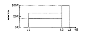
図7は、上記成形における顔料濃度変化のタイミングチャートである。つまり、図7に示すようにt1〜t2の期間における第1注入工程では、基準濃度に対して顔料濃度を40%としてスキン層U2とコア部U3を形成している。また、t2〜t3の期間における第2注入工程では、顔料濃度を基準濃度(100%)として、ゲート近傍部のウレタン樹脂U4を形成している。
【0039】
このように成形した場合、塗膜層の下に設けられるスキン層U2の顔料濃度は基準濃度より低濃度の40%であり、また、コア部U3は発泡されているためスキン層U2より相対的に顔料濃度が低くなり、色が薄い。従って、塗膜層の色とスキン層U2の色とコア部U3の色とが加算された濃度として視覚されるため、表面に露出するウレタン樹脂U4の顔料基準濃度と同程度の着色に見える。
【0040】
また、図7に示す一点鎖線は、塗料Mをスプレーガンで塗布した後にウレタン材料の発泡成形を実施した比較例である。この場合、パーティングラインにバリが発生し、そのバリの除去に伴い高発泡のコア部が露出する。そのため、スキン層とコア部が形成されるt1〜t2の期間において、見栄えが悪化しない程度の顔料濃度(例えば、65%)に高める必要があった。しかしながら、本実施形態によれば、キャビティ17以外に塗料Mが塗布されることが防止され、パーティングラインにおけるバリの発生が抑制されるので、顔料濃度を低減することが可能となる。
【0041】
このようにして、ステアリングホイール1のリング部2及びスポーク部3,4,5のウレタン樹脂の成形と塗装が同時に実施される。つまり、ウレタン樹脂からなる低発泡のスキン層U2及び高発泡のコア部U3が形成され、低発泡のスキン層U2の表面に耐光性のあるウレタン樹脂U1の塗膜がほぼ均一な厚さ(例えば、10μm)で形成される。
【0042】
そして、金型7が開けられて、図4に示すようにリング部2及びスポーク部3,4,5がウレタン樹脂で被覆されたステアリングホイール1が取り出されて成形工程が終了する。
【0043】
なお上述のように、液状のウレタン材料を用いた発泡成形は、一般的な熱可塑性樹脂の射出成形と比較して、キャビティ17内が低温、低圧の条件下で樹脂成形が実施される。従って、キャビティ17の壁面に形成された塗膜層が成形時の圧力や温度によって壊されることが防止される。さらに、減圧状態のキャビティ17に、ウレタン材料が注入されるので、同材料の回り込み不良が低減される。
【0044】
以上記述したように、本実施の形態によれば、以下の効果を奏する。
(1)スキン層U2の顔料濃度は、ゲート近傍部のウレタン樹脂U4と比較して低濃度であるが、気泡がほとんどないことからその着色度合は、ウレタン樹脂U4とほぼ等しくなる。また、塗料Mがキャビティ17以外の部分に塗布されることはなく、発泡成形によって発生するバリを低減できる。従って、バリ除去に伴うコア部U3の露出を防止できる。さらに、スプレーガンで塗布(モールドコート)した場合、塗料Mをキャビティ17に均一に塗布することができず、特にパーティングラインの部分への塗布が不十分となって、その部分の塗膜が薄くなってしまう。しかしながら、本実施形態では、塗料溶液の注入量を制御することによって発泡成形されるスキン層U2の表面に所望の厚さの塗膜をほぼ均一に形成できる。よって、この塗膜によりウレタン樹脂を隠蔽できるので、発泡成形されるスキン層U2及びコア部U3に含まれる顔料濃度の低減が可能となる。また、ゲート残留部としてのウレタン樹脂U5が切除されたとしても、顔料濃度を基準濃度としたウレタン樹脂U4が露出するため、外観の悪化を防止できる。
【0045】
以上のことより、外観を悪化させることなくウレタン材料に含まれる顔料を低減でき、材料コストを低減できる。また、顔料の粒子は、ウレタン注入装置40における通過部分を摩耗させるが、上記のように顔料を低減できるので、その摩耗を低減できる。よって、ウレタン注入装置40のメンテナンス費用の低減が可能となる。
【0046】
(2)ウレタン材料を用いた発泡成形により、高発泡のコア部U3の外側に低発泡のスキン層U2が形成されるので、耐摩耗性、触感等を向上できる。また、耐光性に優れるウレタン樹脂U1の塗膜をステアリングホイール1の樹脂部の表面にほぼ均一な厚さで形成できる。その結果、耐光性がどの場所でも均一に得られ、ウレタン樹脂のスキン層U2の変色を防止できる。また、製品表面の色むらがなく外観不良を防止できる。よって、ステアリングホイール1は、耐摩耗性、触感、耐光性等の製品性能に優れたものとなる。また、ステアリングホイール1を長く使用して塗膜が摩耗したとしても、内部にスキン層U2が形成されているので、外観、触感等の性能を保つことができる。
【0047】
(3)閉じた金型7内において、塗料Mは、その溶剤が沸騰して体積増加及び破泡することによりキャビティ17の壁面に塗布むらが無くほぼ均一に塗布される。この場合、スプレーガンで塗料Mを塗布(モールドコート)した場合に比べて塗着効率を高めることができ、塗料Mの材料費を低減できる。また、塗料Mが外部に飛散することが防止され、作業場をきれいに保つことができ、周囲の環境の悪化を防止することができる。
【0048】
(4)ウレタン材料を用いた発泡成形では、熱可塑性樹脂の射出成形と比べて、キャビティ17内が低温、低圧の条件下で樹脂成形が行われるので、キャビティ17の壁面に塗布された塗膜層が壊れることを防止できる。また、キャビティ17内を減圧させて塗膜層を形成した後に、キャビティ17内を常圧状態とすると、その際の圧力変化によっては塗膜層を壊す虞があるが、本実施形態のように減圧状態を保ちつつウレタン材料を注入することで、塗膜層が壊れることを防止できる。さらに、減圧状態でウレタン材料の発泡成形が実施されるので、同材料の回り込み不良を低減できる。よって、製品の歩留まりを向上できる。
【0049】
(5)芯金10の表面は、塗料Mの溶剤により洗浄され、その芯金10の表面に接着性に優れるウレタン樹脂系の塗料Mが塗布されているため芯金10とウレタン樹脂が強固に固着できる。
【0050】
尚、上記実施形態は、以下の態様で実施してもよい。
○上記実施形態では、第1注入工程(図7のt1〜t2)において、顔料濃度を40%とした第1のウレタン材料を注入してスキン層U2及びコア部U3を形成し、さらに、第2注入工程(図7のt2〜t3)において、顔料濃度を基準濃度(100%)とした第2のウレタン材料を注入してゲート近傍部としてのウレタン樹脂U4を形成するものであったがこれに限定するものではない。例えば、成形品形状、色等によっては、スキン層U2及び塗膜(ウレタン樹脂U1)により内部のコア部U3を確実に隠蔽できる場合もあり、このコア部U3の顔料濃度を低減して発泡成形を行ってもよい。
【0051】
具体的には、図8に示すt1〜t10の期間において、顔料濃度を40%とした第1のウレタン材料を注入してスキン層U2を形成し、t10〜t2の期間において、顔料濃度を0%とし顔料を含まないウレタン材料を注入して内部のコア部U3を形成する。さらに、t2〜t3の期間において、顔料濃度を基準濃度(100%)とした第2のウレタン材料を注入してゲート近傍部としてのウレタン樹脂U4を形成する。勿論、t10〜t2の期間において、顔料濃度が0%のウレタン材料を注入する必要はなく、少なくともt1〜t10の期間に注入される第1のウレタン材料よりも顔料が低減されたウレタン材料(第3のウレタン材料)を注入するものであればよい。なお、図8に示す成形方法では、t1〜t10の期間における注入工程が第1注入工程に相当し、t2〜t3の期間における注入工程が第2注入工程に相当する。また、第1注入工程と第2注入工程との間の注入工程、つまり、t10〜t2の期間の注入工程が第3注入工程に相当する。
【0052】
さらに、成形品形状、色等に応じてスキン層U2及びコア部U3の顔料濃度を適宜変更できる。具体的には、例えば、スキン層U2及びコア部U3が形成されるt1〜t2の期間において、顔料濃度を徐々に低下させて発泡成形を行ってもよい。
【0053】
但し、上記実施形態のようにステアリングホールを成形する場合では、表面用のウレタン材料においては、顔料濃度を基準濃度の40%〜80%に低めることが好ましい。また、内部用のウレタン材料においては、顔料濃度を基準濃度の30%〜70%に低めることが好ましい。
【0054】
○上記実施形態では、金型7を開けた状態で塗料溶液を注入するものであったが、塗料注入装置を別に設けて、金型7を型締めした状態で塗料注入装置からキャビティ17に塗料Mを注入するように構成してもよい。このようにすれば、キャビティ17の減圧中に塗料溶液を注入でき、短時間で樹脂成形を実施できるようになる。また、閉じたキャビティ17内に塗料溶液が注入されるので塗料Mの溶剤が射出成形機の外部に漏れることを防止できる。
【0055】
○成形品は、ステアリングホイール1に限定されず、例えば、インストルメントパネル、コンソールボックス、グローボックス、ヘッドレスト、アームレスト、ドアカバー、エアスポイラー、バンパー等の他の部品にも適用できる。勿論、自動車部品以外に家電製品等の成形品に適用してもよい。
【0056】
○塗料Mの成分を適宜変更して実施してもよい。具体的には、ウレタン樹脂に代えて、他の熱硬化性樹脂を用いてもよい。また、塗料Mの溶剤として、メチルエチルケトン(MEK)及びイソプロピルアルコール(IPA)以外の溶剤、例えば水等を用いてもよい。或いは、MEK,IPAの溶剤にトルエン等を加えるものでもよい。実用的には、沸点が約160℃以下の溶剤を用いるものであればよい。
【0057】
○上記実施形態では、真空ポンプ34を駆動してキャビティ17内を50torrまで減圧するものであったが、これに限定するものではない。塗料溶液の乾燥時間、塗布状態、或いは、スキン層U2の厚さ等の条件に応じてキャビティ17内の減圧状態を適宜変更して実施してもよい。
【0058】
さらに、上記実施形態により把握される請求項以外の技術的思想について、以下にそれらの効果とともに記載する。
(イ) 請求項1に記載のウレタン成形品の製造方法において、前記発泡成形は、顔料濃度を基準濃度よりも低い所定濃度としたウレタン材料を注入して低発泡のスキン層を形成する工程と、顔料濃度を基準濃度よりも低い所定濃度としたウレタン材料を注入して高発泡のコア部を形成する工程と、顔料濃度を基準濃度としたウレタン材料を注入して前記ゲート近傍部を形成する工程とを備えることを特徴とするウレタン成形品の製造方法。減圧状態のキャビティにウレタン材料を注入して発泡成形を実施した場合、高発泡のコア部の外側に低発泡のスキン層が形成される。このスキン層の顔料濃度を低減しても、気泡がほとんどないことから基準濃度のゲート近傍部とほぼ同程度の色と視覚される。また、スキン層の外側には、ほぼ均一の厚さ塗膜が形成され、この塗膜とスキン層によってコア部の隠蔽が可能となる。従って、スキン層を形成する工程とコア部を形成する工程における顔料濃度を低減できる。
【0059】
(ロ) 技術的思想(イ)に記載のウレタン成形品の製造方法において、前記コア部を形成する工程における顔料濃度を前記スキン層を形成する工程よりも低減したことを特徴とするウレタン成形品の製造方法。つまり、塗膜とスキン層により内部のコア部が隠蔽される場合では、コア部を形成する工程における顔料濃度をより低減できる。
【0060】
【発明の効果】
以上詳述したように、本発明によれば、外観を悪化させることなく、ウレタン材料に含まれる顔料を低減できる。
【図面の簡単な説明】
【図1】実施形態のステアリングホイールの成形方法を説明するための図。
【図2】実施形態のステアリングホイールの成形方法を説明するための図。
【図3】実施形態のステアリングホイールの成形方法を説明するための図。
【図4】実施形態のステアリングホイールの斜視図。
【図5】実施形態のウレタン注入装置の概略構成図。
【図6】実施形態のステアリングホイールのリング部における拡大断面図。
【図7】実施形態の発泡成形の顔料濃度変化を示すタイミングチャート。
【図8】別の発泡成形の顔料濃度変化を示すタイミングチャート。
【符号の説明】
1…ウレタン成形品としてのステアリングホイール、7…金型、17…キャビティ、M…塗料、U4…ゲート近傍部としてのウレタン樹脂。[0001]
TECHNICAL FIELD OF THE INVENTION
The present invention relates to a method for producing a urethane molded product in which a coating material is applied in advance to a cavity in a mold in order to simultaneously perform molding and coating, and then a urethane material is injected and foamed.
[0002]
[Prior art]
As this type of molded product, for example, there is a steering wheel for a vehicle. The steering wheel is subjected to foam molding by setting a core metal in a mold cavity (a cavity for forming a molded product) and then injecting a urethane material into the mold cavity. In the case of a steering wheel made of a urethane material, it is necessary to form a skin layer on the surface of the steering wheel in order to improve the appearance, feel, abrasion resistance, and the like. A method of injecting a urethane material into the material has been put to practical use by the present applicant (Japanese Patent No. 2518481).
[0003]
Specifically, when a urethane material is injected into a mold cavity under reduced pressure, the gas contained in the urethane material is bumped under reduced pressure to form gas bubbles. It is filled while flowing. A urethane reaction starts in parallel with the foaming of the urethane material, and reaction hardening proceeds. At this time, since the reaction heat escapes to the mold in the portion close to the cavity surface, the urethane reaction is delayed, and the increase in the viscosity of the urethane material is suppressed. Therefore, the gas bubbles on the surface are degassed under reduced pressure to form a low foaming skin layer. On the other hand, in the interior away from the cavity surface, the thickening due to the urethane reaction progresses, the gas bubbles are held as they are, and a highly foamed core portion is formed. In this case, a low-foaming skin layer is formed on the surface of the high-foaming core portion, and the appearance, tactile sensation, wear resistance, and the like of the steering wheel surface are improved.
[0004]
However, since the urethane resin molded by the foam molding as described above has a defect of being inferior in light resistance and yellowing, it is necessary to form a coating film having light resistance on the surface of the urethane resin portion.
[0005]
As a method of forming the coating film, a method of applying a coating material in advance to a cavity in a mold and then molding a product is applied. Specifically, the mold is opened, and a coating solution is applied to the cavity by a spray gun (mold coating). Thereafter, the mold is closed, and a urethane material is mixed and injected into the cavity to be cured by reaction. Thereby, a coating film is formed on the surface of the molded article. The coating solution used here is composed of, for example, methyl ethyl ketone (MEK) and isopropyl alcohol (IPA) as solvents, and a urethane resin having excellent light resistance.
[0006]
[Problems to be solved by the invention]
By the way, in the above-mentioned urethane resin foam molding, the urethane material injected first into the cavity becomes a low-foaming skin layer, and the urethane material injected later becomes the highly foamed core portion. Therefore, a molding method for reducing the pigment by injecting a urethane material containing a pigment to form a low-foaming skin layer and injecting a urethane material containing no pigment to form a highly foamed core portion. It has been proposed by the present applicant (Japanese Patent Application Laid-Open No. 9-183138). Further, in this molding method, as a measure to prevent the uncolored core portion from being exposed on the surface by cutting off the gate remaining portion, a urethane material containing a pigment is injected in the final step of foam molding. ing.
[0007]
However, when the coating solution is applied (mold coated) by the spray gun as described above, the coating cannot be applied to the cavity accurately. Therefore, the paint applied to portions other than the cavities causes burrs in the foam molding. Since the burrs have a cross-sectional structure in which a core portion containing no pigment penetrates between skin layers containing pigments, when the burrs are removed by a burr treatment process, an uncolored core portion is exposed on the surface to deteriorate the appearance. I will.
[0008]
The present invention has been made to solve the above problems, and an object of the present invention is to provide a method for producing a urethane molded article capable of reducing the amount of pigment contained in a urethane material without deteriorating the appearance. .
[0009]
[Means for Solving the Problems]
In order to achieve the above object, an invention according to claim 1 is a method for producing a urethane molded product in which a urethane material is injected and foamed, wherein a solvent and a solvent are mixed in a mold cavity in a state where a mold is closed. A coating in which a coating solution containing a urethane resin is boiled, and the coating is applied to the surface of the mold cavity by increasing the volume at the time of boiling and breaking bubbles, and the vaporized solvent is exhausted to form a coating layer on the surface of the mold cavity. A first injecting step of injecting a first urethane material containing a pigment into the mold cavity, and a second injecting step of injecting a second urethane material containing more pigment than the first urethane material The gist is that it consists of:
[0010]
According to a second aspect of the present invention, in the first aspect of the invention, the gist is that the coating step is performed under reduced pressure.
According to a third aspect of the present invention, in the first aspect, the first injection step is performed under reduced pressure.
[0011]
In the invention according to claim 4, in the invention according to claim 1, between the first injection step and the second injection step, the pigment is further reduced from the first urethane material, or the pigment is contained. The gist of the present invention is to include a third injection step of injecting a third urethane material.
[0012]
(Action)
According to the first aspect of the present invention, a paint solution containing a solvent and a urethane resin is boiled in a mold cavity in a state where the mold is closed. The solvent applied to the surface of the cavity and the vaporized solvent are exhausted to form a coating layer on the mold cavity. Then, the first urethane material having a reduced pigment concentration is injected into the mold cavity in a reduced pressure state, and foam molding of the urethane material is performed. Thereafter, a second urethane material containing more pigment than the first urethane material is injected, and the vicinity of the gate is foamed. As described above, when the coating layer is formed in the mold cavity with the mold closed, the generation of burrs during foam molding is suppressed, so that the amount of pigment contained in the urethane material can be reduced.
[0013]
According to the second aspect of the present invention, the coating solution is boiled in the mold cavity by setting the mold cavity in a reduced pressure state, and the coating layer is formed in the mold cavity due to an increase in volume at the time of boiling and breakage of bubbles. It is formed with a substantially uniform thickness. In this case, a coating layer having a desired thickness is formed almost uniformly on the surface of the urethane material to be foam-molded by controlling the injection amount of the coating solution. Therefore, the pigment contained in the first urethane material can be reduced.
[0014]
According to the third aspect of the present invention, when the first urethane material is injected into the mold cavity under reduced pressure, a low-foaming skin layer is formed by the first injected urethane material, and then the injection is performed. The highly foamed core portion is formed by the urethane material to be used. When molded in this manner, the pigment concentration of the skin layer is lower than that of the urethane resin in the vicinity of the gate, but since there are almost no bubbles, the degree of coloring is substantially equal to that of the vicinity of the gate. Further, unlike the prior art, the coating material is not applied to a portion other than the cavity, and burrs generated by foam molding are reduced. Therefore, the exposure of the core portion due to the removal of burrs is prevented, and the amount of pigment contained in the first urethane material can be reduced. .
[0015]
According to the invention as set forth in claim 4, a low-foaming skin layer is formed on the surface of the molded article by the first urethane material, and the pigment is further reduced or contains the pigment than the first urethane material. The inner core of the skin layer is formed by the third urethane material.
[0016]
In the first urethane material for the surface, it is preferable to lower the pigment concentration to 40% to 80% of the reference concentration. In the internal third urethane material, it is preferable to lower the pigment concentration to 30% to 70% of the reference concentration.
[0017]
BEST MODE FOR CARRYING OUT THE INVENTION
Hereinafter, embodiments of the present invention will be described with reference to the drawings.
1 to 3 are partial cross-sectional views of an injection molding machine according to the present embodiment, and FIG. 4 is a perspective view of a vehicle steering wheel 1 molded by the injection molding machine.
[0018]
As shown in FIG. 4, the steering wheel 1 has a ring portion 2, spoke
[0019]
As shown in FIGS. 1 to 3, the mold 7 is disposed in a box 13 including a frame 11 and a lid 12. Specifically, the lower die 8 of the die 7 is fixed to the frame 11, and the upper die 9 of the die 7 is fixed to the lid 12. In addition, a
[0020]
[0021]
A
[0022]
An
[0023]
Here, a schematic configuration of the
As shown in FIG. 5, the
[0024]
A through
[0025]
A
[0026]
A
[0027]
A
[0028]
As described above, the coloring material discharged from the discharge holes 64, the polyol component discharged from the
[0029]
Next, a method of molding the urethane resin of the steering wheel 1 in the present embodiment will be described with reference to FIGS.
First, as shown in FIG. 1, the mold 7 is opened, and a mold release agent is applied to the wall surfaces of the cavity 17 (the
[0030]
Next, the liquid paint M (in this embodiment, 170 g) is poured into the
[0031]
Then, as shown in FIG. 2, the
[0032]
Specifically, the inside of the box 13 is depressurized by driving the
[0033]
Then, the solvent of the paint M is vaporized, and the urethane resin of the paint M is applied to the wall surface of the
[0034]
Then, while maintaining the reduced pressure, the urethane material mixed by the
[0035]
Specifically, the
[0036]
Then, the gas contained in the urethane material is suddenly boiled under reduced pressure and becomes a myriad of gas bubbles, so that the urethane material foams in a short time and fills the
[0037]
Thereafter, a urethane material whose pigment concentration is adjusted to the reference concentration (100%) by increasing the amount of the coloring component discharged from the
[0038]
FIG. 7 is a timing chart of a change in pigment concentration in the molding. That is, as shown in FIG. 7, in the first injection step in the period from t1 to t2, the pigment concentration is 40% with respect to the reference concentration, and the skin layer U2 and the core portion U3 are formed. In the second injection step during the period from t2 to t3, the urethane resin U4 near the gate is formed with the pigment concentration as the reference concentration (100%).
[0039]
When molded in this manner, the pigment concentration of the skin layer U2 provided below the coating layer is 40%, which is lower than the reference concentration, and the core portion U3 is foamed, so that the pigment concentration is lower than that of the skin layer U2. The pigment concentration is low and the color is light. Therefore, since the color of the coating layer, the color of the skin layer U2, and the color of the core portion U3 are visually recognized as the added density, the coloring looks almost the same as the pigment reference density of the urethane resin U4 exposed on the surface.
[0040]
The dashed line shown in FIG. 7 is a comparative example in which the coating material M was applied by a spray gun and then the urethane material was subjected to foam molding. In this case, burrs are generated on the parting line, and the highly foamed core is exposed as the burrs are removed. Therefore, in the period from t1 to t2 when the skin layer and the core portion are formed, it is necessary to increase the pigment concentration (for example, 65%) to such an extent that the appearance is not deteriorated. However, according to the present embodiment, the coating material M is prevented from being applied to portions other than the
[0041]
In this manner, the molding and coating of the urethane resin of the ring portion 2 and the
[0042]
Then, the mold 7 is opened, and as shown in FIG. 4, the steering wheel 1 in which the ring portion 2 and the
[0043]
As described above, in the foam molding using the liquid urethane material, the resin molding is performed under the condition of low temperature and low pressure in the
[0044]
As described above, the present embodiment has the following advantages.
(1) The pigment concentration of the skin layer U2 is lower than that of the urethane resin U4 in the vicinity of the gate. However, since there are almost no bubbles, the degree of coloring is almost equal to that of the urethane resin U4. Further, the coating material M is not applied to a portion other than the
[0045]
As described above, the pigment contained in the urethane material can be reduced without deteriorating the appearance, and the material cost can be reduced. In addition, the pigment particles wear the passing portion in the
[0046]
(2) Since the low-foaming skin layer U2 is formed outside the high-foaming core portion U3 by foam molding using a urethane material, wear resistance, tactile sensation, and the like can be improved. Further, a coating film of the urethane resin U1 having excellent light resistance can be formed on the surface of the resin portion of the steering wheel 1 with a substantially uniform thickness. As a result, light resistance can be uniformly obtained at any place, and discoloration of the urethane resin skin layer U2 can be prevented. In addition, there is no unevenness in color on the product surface, so that poor appearance can be prevented. Therefore, the steering wheel 1 has excellent product performance such as wear resistance, tactile sensation, and light resistance. Further, even if the coating film is worn by using the steering wheel 1 for a long time, the skin layer U2 is formed inside, so that the performance such as the appearance and the touch can be maintained.
[0047]
(3) In the closed mold 7, the coating material M is applied almost uniformly without uneven application on the wall surface of the
[0048]
(4) In foam molding using a urethane material, resin molding is performed under low-temperature and low-pressure conditions in the
[0049]
(5) The surface of the
[0050]
The above embodiment may be implemented in the following modes.
In the above embodiment, in the first injection step (t1 to t2 in FIG. 7), the first urethane material having a pigment concentration of 40% is injected to form the skin layer U2 and the core portion U3. In the second injection step (t2 to t3 in FIG. 7), the second urethane material having the pigment concentration as the reference concentration (100%) is injected to form the urethane resin U4 as a portion near the gate. It is not limited to. For example, depending on the shape, color, etc. of the molded product, the skin layer U2 and the coating film (urethane resin U1) can reliably cover the inner core portion U3. May be performed.
[0051]
Specifically, a skin layer U2 is formed by injecting a first urethane material having a pigment concentration of 40% in a period from t1 to t10 shown in FIG. % And a pigment-free urethane material is injected to form an inner core portion U3. Further, during a period from t2 to t3, a second urethane material having a pigment concentration as a reference concentration (100%) is injected to form a urethane resin U4 as a portion near the gate. Of course, in the period from t10 to t2, it is not necessary to inject a urethane material having a pigment concentration of 0%, and at least the urethane material in which the pigment is reduced compared to the first urethane material injected in the period from t1 to t10 (the second urethane material). 3 urethane material). In the molding method shown in FIG. 8, the injection step in the period from t1 to t10 corresponds to the first injection step, and the injection step in the period from t2 to t3 corresponds to the second injection step. Further, an implantation step between the first implantation step and the second implantation step, that is, an implantation step in a period from t10 to t2 corresponds to a third implantation step.
[0052]
Further, the pigment concentration of the skin layer U2 and the core portion U3 can be appropriately changed according to the shape, color, and the like of the molded product. Specifically, for example, during the period from t1 to t2 when the skin layer U2 and the core portion U3 are formed, the foaming may be performed by gradually lowering the pigment concentration.
[0053]
However, when the steering hole is formed as in the above embodiment, it is preferable to reduce the pigment concentration of the urethane material for the surface to 40% to 80% of the reference concentration. In the urethane material for the inside, it is preferable to lower the pigment concentration to 30% to 70% of the reference concentration.
[0054]
In the above embodiment, the paint solution is injected with the mold 7 opened. However, a paint injecting device is separately provided, and the paint is injected from the paint injecting device into the
[0055]
The molded product is not limited to the steering wheel 1, but may be applied to other parts such as an instrument panel, a console box, a glow box, a headrest, an armrest, a door cover, an air spoiler, and a bumper. Of course, the present invention may be applied to molded articles such as home electric appliances in addition to automobile parts.
[0056]
-The components of the coating material M may be changed as appropriate. Specifically, another thermosetting resin may be used instead of the urethane resin. Further, as the solvent of the coating material M, a solvent other than methyl ethyl ketone (MEK) and isopropyl alcohol (IPA), for example, water may be used. Alternatively, toluene or the like may be added to the MEK or IPA solvent. Practically, any solvent using a solvent having a boiling point of about 160 ° C. or less may be used.
[0057]
In the above embodiment, the inside of the
[0058]
Further, technical ideas other than the claims grasped by the above embodiment will be described below together with their effects.
(A) In the method for producing a urethane molded article according to claim 1, the foam molding includes a step of injecting a urethane material having a predetermined concentration lower than a reference concentration to form a low-foaming skin layer. Forming a highly foamed core portion by injecting a urethane material having a predetermined concentration lower than the reference concentration to form a highly foamed core portion, and forming the vicinity of the gate by injecting a urethane material having the pigment concentration as the reference concentration And a process for producing a urethane molded article. When the urethane material is injected into the cavity in the reduced pressure state and foam molding is performed, a low foam skin layer is formed outside the high foam core. Even if the pigment concentration of the skin layer is reduced, the color is almost the same as that of the vicinity of the gate having the reference concentration because there are almost no bubbles. Further, a coating film having a substantially uniform thickness is formed on the outer side of the skin layer, and the core portion can be hidden by the coating film and the skin layer. Therefore, the pigment concentration in the step of forming the skin layer and the step of forming the core can be reduced.
[0059]
(B) The method for producing a urethane molded product according to the technical concept (a), wherein the pigment concentration in the step of forming the core portion is lower than that in the step of forming the skin layer. Manufacturing method. That is, when the inner core portion is hidden by the coating film and the skin layer, the pigment concentration in the step of forming the core portion can be further reduced.
[0060]
【The invention's effect】
As described in detail above, according to the present invention, the pigment contained in the urethane material can be reduced without deteriorating the appearance.
[Brief description of the drawings]
FIG. 1 is a view for explaining a method of forming a steering wheel according to an embodiment.
FIG. 2 is a diagram for explaining a steering wheel forming method according to the embodiment.
FIG. 3 is a view for explaining a method of forming the steering wheel according to the embodiment.
FIG. 4 is a perspective view of the steering wheel of the embodiment.
FIG. 5 is a schematic configuration diagram of a urethane injection device of the embodiment.
FIG. 6 is an enlarged sectional view of a ring portion of the steering wheel according to the embodiment.
FIG. 7 is a timing chart showing a change in pigment concentration in foam molding according to the embodiment.
FIG. 8 is a timing chart showing a pigment concentration change in another foam molding.
[Explanation of symbols]
1 ... Steering wheel as urethane molded product, 7 ... Mold, 17 ... Cavity, M ... Paint, U4 ... Urethane resin as gate vicinity.
Claims (4)
金型を閉じた状態の金型キャビティ内で、溶剤とウレタン樹脂とを含む塗料溶液を沸騰させ、沸騰時の体積増加及び破泡により塗料を金型キャビティの表面に塗布すると共に気化した溶剤を排気して塗膜層を金型キャビティ表面に形成する塗装工程と、
金型キャビティ内に顔料を含んだ第1のウレタン材料を注入する第1注入工程と、
前記第1のウレタン材料より顔料を多く含んだ第2のウレタン材料を注入する第2注入工程とからなるウレタン成形品の製造方法。In a method for producing a urethane molded product in which a urethane material is injected and subjected to foam molding,
In a mold cavity with the mold closed, a paint solution containing a solvent and a urethane resin is boiled. A coating process of evacuating and forming a coating layer on the surface of the mold cavity,
A first injection step of injecting a first urethane material containing a pigment into the mold cavity;
A second injection step of injecting a second urethane material containing more pigment than the first urethane material.
前記塗装工程は、減圧状態で行うことを特徴とするウレタン成形品の製造方法。The method for producing a urethane molded product according to claim 1,
The method for producing a urethane molded product, wherein the coating step is performed under reduced pressure.
前記第1注入工程は、減圧下で行うことを特徴とするウレタン成形品の製造方法。The method for producing a urethane molded product according to claim 1,
The method for producing a urethane molded product, wherein the first injection step is performed under reduced pressure.
前記第1注入工程と第2注入工程との間に、第1のウレタン材料より顔料がさらに低減された、もしくは顔料を含まない第3のウレタン材料を注入する第3注入工程を含むことを特徴とするウレタン成形品の製造方法。The method for producing a urethane molded product according to claim 1,
A third injection step of injecting a third urethane material containing less or no pigment than the first urethane material is included between the first injection step and the second injection step. A method for producing a urethane molded product.
Priority Applications (10)
| Application Number | Priority Date | Filing Date | Title |
|---|---|---|---|
| JP27619399A JP3573019B2 (en) | 1999-09-29 | 1999-09-29 | Manufacturing method of urethane molded product |
| EP00104859A EP1040906B1 (en) | 1999-03-31 | 2000-03-07 | Process for producing polyurethane molded articles |
| EP20000104858 EP1088648B1 (en) | 1999-09-29 | 2000-03-07 | Process for forming coating film |
| DE60007209T DE60007209T2 (en) | 1999-03-31 | 2000-03-07 | Process for the production of polyurethane moldings |
| DE2000607050 DE60007050T2 (en) | 1999-09-29 | 2000-03-07 | IMC process |
| AU20753/00A AU739153B2 (en) | 1999-09-29 | 2000-03-08 | Molded product having a coating film and process for forming coating film |
| US09/522,045 US6607681B1 (en) | 1999-09-29 | 2000-03-09 | Molded product having a coating film and process for forming coating film |
| US09/522,064 US6383423B1 (en) | 1999-03-31 | 2000-03-09 | Process for producing polyurethane molded articles |
| CNB001031732A CN1251857C (en) | 1999-09-29 | 2000-03-17 | Coated injecting products and method for forming coating |
| US10/383,627 US20030172769A1 (en) | 1999-09-29 | 2003-03-10 | Molded product having coating film |
Applications Claiming Priority (1)
| Application Number | Priority Date | Filing Date | Title |
|---|---|---|---|
| JP27619399A JP3573019B2 (en) | 1999-09-29 | 1999-09-29 | Manufacturing method of urethane molded product |
Publications (2)
| Publication Number | Publication Date |
|---|---|
| JP2001096547A JP2001096547A (en) | 2001-04-10 |
| JP3573019B2 true JP3573019B2 (en) | 2004-10-06 |
Family
ID=17566005
Family Applications (1)
| Application Number | Title | Priority Date | Filing Date |
|---|---|---|---|
| JP27619399A Expired - Fee Related JP3573019B2 (en) | 1999-03-31 | 1999-09-29 | Manufacturing method of urethane molded product |
Country Status (1)
| Country | Link |
|---|---|
| JP (1) | JP3573019B2 (en) |
-
1999
- 1999-09-29 JP JP27619399A patent/JP3573019B2/en not_active Expired - Fee Related
Also Published As
| Publication number | Publication date |
|---|---|
| JP2001096547A (en) | 2001-04-10 |
Similar Documents
| Publication | Publication Date | Title |
|---|---|---|
| EP1088648B1 (en) | Process for forming coating film | |
| US5049327A (en) | Injection molding method | |
| EP1040906B1 (en) | Process for producing polyurethane molded articles | |
| JP2003159724A (en) | Method for coating and molding inside of mold | |
| JP3573019B2 (en) | Manufacturing method of urethane molded product | |
| JP3573020B2 (en) | Urethane molded product manufacturing equipment | |
| JP2000094468A (en) | Lightweight molding, coated lightweight molding and manufacture thereof | |
| JP4193305B2 (en) | Manufacturing method of molded products | |
| JP3358416B2 (en) | RIM polyurethane two-color molding method | |
| JP3573013B2 (en) | Manufacturing method of molded products | |
| JPH08142103A (en) | Manufacture of decorated molded body using rased skin material, and metal mold therefor | |
| JP3573015B2 (en) | Manufacturing method of molded products | |
| AU766039B2 (en) | Molded product | |
| JP4120088B2 (en) | RIM polyurethane molding method and polyurethane molded article | |
| JP3584806B2 (en) | How to apply paint in mold | |
| JP3573014B2 (en) | Method for manufacturing resin molded products | |
| JP3573016B2 (en) | Method of manufacturing molded article made of urethane resin | |
| JP3573018B2 (en) | Method for manufacturing resin molded products | |
| JP3772605B2 (en) | Manufacturing method of insert molded product and insert molded product | |
| JP3573017B2 (en) | How to apply paint in mold | |
| JPH10654A (en) | Rim polyurethane bicolor molding | |
| JP2000280286A (en) | Method for two-color molding of rim polyurethane | |
| JPS63307912A (en) | Preparation of foamed molded product | |
| JPH10653A (en) | Rim polyurethane bicolor molding | |
| JPH10652A (en) | Rim polyurethane bicolor molded item |
Legal Events
| Date | Code | Title | Description |
|---|---|---|---|
| TRDD | Decision of grant or rejection written | ||
| A01 | Written decision to grant a patent or to grant a registration (utility model) |
Free format text: JAPANESE INTERMEDIATE CODE: A01 Effective date: 20040608 |
|
| A61 | First payment of annual fees (during grant procedure) |
Free format text: JAPANESE INTERMEDIATE CODE: A61 Effective date: 20040621 |
|
| R150 | Certificate of patent or registration of utility model |
Free format text: JAPANESE INTERMEDIATE CODE: R150 |
|
| FPAY | Renewal fee payment (event date is renewal date of database) |
Free format text: PAYMENT UNTIL: 20080709 Year of fee payment: 4 |
|
| FPAY | Renewal fee payment (event date is renewal date of database) |
Free format text: PAYMENT UNTIL: 20080709 Year of fee payment: 4 |
|
| FPAY | Renewal fee payment (event date is renewal date of database) |
Free format text: PAYMENT UNTIL: 20090709 Year of fee payment: 5 |
|
| FPAY | Renewal fee payment (event date is renewal date of database) |
Free format text: PAYMENT UNTIL: 20090709 Year of fee payment: 5 |
|
| FPAY | Renewal fee payment (event date is renewal date of database) |
Free format text: PAYMENT UNTIL: 20100709 Year of fee payment: 6 |
|
| FPAY | Renewal fee payment (event date is renewal date of database) |
Free format text: PAYMENT UNTIL: 20110709 Year of fee payment: 7 |
|
| FPAY | Renewal fee payment (event date is renewal date of database) |
Free format text: PAYMENT UNTIL: 20120709 Year of fee payment: 8 |
|
| FPAY | Renewal fee payment (event date is renewal date of database) |
Free format text: PAYMENT UNTIL: 20120709 Year of fee payment: 8 |
|
| FPAY | Renewal fee payment (event date is renewal date of database) |
Free format text: PAYMENT UNTIL: 20130709 Year of fee payment: 9 |
|
| LAPS | Cancellation because of no payment of annual fees |