JP3572236B2 - Electric dust collector - Google Patents
Electric dust collector Download PDFInfo
- Publication number
- JP3572236B2 JP3572236B2 JP2000048421A JP2000048421A JP3572236B2 JP 3572236 B2 JP3572236 B2 JP 3572236B2 JP 2000048421 A JP2000048421 A JP 2000048421A JP 2000048421 A JP2000048421 A JP 2000048421A JP 3572236 B2 JP3572236 B2 JP 3572236B2
- Authority
- JP
- Japan
- Prior art keywords
- dust
- perforated plate
- containing gas
- duct
- flow
- Prior art date
- Legal status (The legal status is an assumption and is not a legal conclusion. Google has not performed a legal analysis and makes no representation as to the accuracy of the status listed.)
- Expired - Fee Related
Links
Images


Description
【0001】
【発明の属する技術分野】
本発明は、電気集塵装置の改良に関する。
【0002】
【従来の技術】
従来の電気集塵装置の概略横断面図である図17において、入口ダクト1は、拡大ダクト2を介してケーシング4の一端に接続されている。そして、ケーシング4の他端は、絞りダクト5を介して出口ダクト6に接続されている。
【0003】
拡大ダクト2内には、多数の通気孔を形成した多孔板3,3’が配設され、またケーシング4内には、含塵ガスの流通方向に沿って集塵部E1,E2が順次配設されている。これらの集塵部E1,E2は、ケーシング3の幅方向に平行配列する多数の放電極7と、これらの放電極7に対向する態様で配列する多数の集塵極8とを備えている。
【0004】
含塵ガスは、入口ダクト1を介して拡大ダクト2に流入し、この拡大ダクト2の拡散作用によってその流速が低下する。そして、多孔板3,3’によってその流れが一様化された後、集塵部E1,E2を順次通過する。
集塵部E1,E2の放電極7と集塵極8間では、それらに印可された高電圧によってコロナ放電が発生する。したがって、放電極7と集塵極8間に流入する含塵ガス中のダスト(例えば、S03 の微粒子)は、上記コロナ放電によって荷電された後、放電極7と集塵極8間に作用するクーロン力によって集塵極8に捕集される。
なお、湿式の電気集塵装置においては、集塵極8に捕集されたダストが洗浄液によって洗い流される。また、集塵部E2を通過した除塵済みのガスは、絞りダクト5を介して出口ダクト6に排出される。
【0005】
【発明が解決しようとする課題】
上記電気集塵装置においては、集塵部E1,E2における含塵ガスの流速分布を一様化するために多孔板3,3’を設けている。しかし、含塵ガスの流通路の形状や、入口ダクト1に流入する含塵ガスの流速分布の偏り等の影響を受けて、実際には、流速分布が十分に一様化されず、そのため、集塵効率が低下するという問題を生じている。
本発明の課題は、このような状況に鑑み、含塵ガスの流速分布をより一様化して集塵効率を向上することができる電気集塵装置を提供することにある。
【0006】
【課題を解決するための手段】
請求項1に係る発明は、拡大ダクトによって拡散された含塵ガスを、該拡大ダクトに配設した第1の多孔板を介して集塵部に流入させ、この集塵部から流出する除塵済みのガスを絞りダクトを介して排出するように構成された電気集塵装置であって、前記絞りダクトに第2の多孔板を配設するようにしている。
請求項2に係る発明は、請求項1の発明において、前記第2の多孔板の開口率を10〜30%に設定している。
請求項3に係る発明は、拡大ダクトによって拡散された含塵ガスを、該拡大ダクトに配設した第1の多孔板を介して集塵部に流入させるように構成された電気集塵装置であって、前記拡大ダクトに前記含塵ガスを送り込む入口ダクトに第2の多孔板を配設している。
請求項4に係る発明は、拡大ダクトによって拡散された含塵ガスを、該拡大ダクトに配設した多孔板を介して集塵部に流入させるように構成された電気集塵装置であって、前記拡大ダクトの上壁および下壁の拡がり方向長と、両側壁の拡がり方向長とを一致もしくは近似させた構成を有する。
請求項5に係る発明は、拡大ダクトによって拡散された含塵ガスを、該拡大ダクトに配設した多孔板を介して集塵部に流入させるように構成された電気集塵装置であって、前記多孔板の通気孔を、前記含塵ガスの流速分布に対応したパターンの開口率が設定されるように設けている。
請求項6に係る発明は、請求項5の発明において、前記多孔板を複数の領域に区分し、それらの領域の開口率を異ならせることによって前記含塵ガスの流速分布に対応した開口率を設定している。
請求項7に係る発明は、請求項5または6の発明において、前記多孔板に、開口率の一定な別の多孔板を併設した構成を有する。
請求項8の発明は、拡大ダクトによって拡散された含塵ガスを、該拡大ダクトに配設した多孔板を介して集塵部に流入させるように構成された電気集塵装置であって、前記多孔板に、該多孔板の面から突出する整流板を同心状に多列形成している。
【0007】
【発明の実施の形態】
以下、図面を参照して本発明の実施の形態について説明する。なお、以下の説明において参照する図においては、図17に示す要素と同一もしくは類似の要素に共通する符号を付してある。そして、以下においては、これらの要素についての説明を省略する。
【0008】
(第1の実施形態)
図1は、本発明に係る電気集塵装置の第1の実施形態を示している。この電気集塵装置は、絞りダクト5の入口端部に多孔板10を配設してあり、この点で図17に示した従来装置と構成が相違する。
【0009】
上記多孔板10の開口率(全面積に対する開口部の比率)は、拡大ダクト2に設けられている多孔板3,3’の開口率よりも低く設定される。すなわち、多孔板3,3’の開口率は、たとえば55%程度に設定されるが、多孔板10の開口率は、たとえば10〜30%に設定される。
【0010】
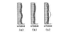
図2の(a),(b)および(c)は、それぞれ図1のA−A断面、B−B断面およびC−C断面におけるガスの流速分布を例示している。
ここで、上記多孔板10を配設しない場合を考えると、この場合、集塵部E2から流出するガスの流速分布は、図2(c)に鎖線で示すように、絞りダクト5および出口ダクト6の影響のためにケーシング4の中央部側で流速が大きくなる傾向の偏りを生じる。そして、このことは、集塵部E2を流通する含塵ガスの流速分布も同様な偏りをもつことを示唆している。
【0011】
これに対して、上記多孔板10を配設したこの第1の実施形態に係る電気集塵装置によれば、該多孔板10の抵抗作用によってケーシング4の中央部を流通するガスの速度が抑制されるので、図2(c)に実線で示すように、ガスの流速分布の偏りが是正されて、集塵部E2に一様な速度分布のガスが流通することになる。
かくして、この実施形態の電気集塵装置によれば、集塵部E1およびE2に一様な分布の含塵ガスが流通させて、集塵効率を向上することができる。
【0012】
(第2の実施形態)
図3は、本発明に係る電気集塵装置の第2の実施形態を示している。この電気集塵装置は、入口ダクト1の出口側端部に多孔板11を配設してあり、この点で図17に示した従来装置と構成が異なる。
電気集塵装置の入口ダクト1には、脱硫装置12から排出される含塵ガス(例えば、SO3 の微粒子)が連結ダクト13を介して流入する。なお、連結ダクト13の各コーナー部には、必要に応じて整流板14が配設される。
【0013】
脱硫装置12から排出される含塵ガスは、該脱硫装置12の構成上、符号13aに示すように流速分布が大きく偏っている。そして、この含塵ガスは、符号13bおよび13cで示すように、ほぼ当初の流速分布を維持した状態で連結ダクト13内を流通する。
【0014】
ここで、入口ダクト1に上記多孔板11を設けない場合を考えると、この場合には、偏りの大きな流速分布をもつ含塵ガスが拡大ダクト2内にそのまま流入することになる。
拡大ダクト2に設けられた多孔板3,3’は、流路の拡大に伴う流速分布の偏りを補正する目的で設けられているので、当初から流速分布が偏った含塵ガスが拡大ダクト2に流入した場合、多孔板3,3’から流出する含塵ガスの流速の一様性が損なわれることになる。すなわち、多孔板3,3’から流出する含塵ガスは、鎖線で例示したように、上記流速分布の偏りに起因した流速分布の乱れを生じる。
【0015】
これ対して、入口ダクト1に多孔板11を配設した上記第2の実施形態に係る電気集塵装置によれば、該入口ダクト1に偏りの大きな流速分布をもつ含塵ガスが流入した場合でも、上記多孔板11によって該ガスの流速が一様化されるので(符号11a参照)、多孔板3,3’から流出する含塵ガスの流速分布も、実線で示すように一様化される。
それ故、この第2実施形態の電気集塵装置によれば、集塵部E1に一様な分布の含塵ガスを流入させて、集塵効率を向上することができる。なお上記多孔板11は、必要に応じて複数枚多段配置することも可能である。
【0016】
(第3の実施形態)
図4は、本発明に係る電気集塵装置の第3の実施形態を示している。なお、図4(a)は、ケーシング4を入口ダクト1側から見た正面図、図4(b)は、図4(a)のD−D断面図、図4(c)は、図4(a)のE−E断面図である。
【0017】
この電気集塵装置は、拡大ダクト2の上壁2aおよび下壁2bの拡がり方向長Δyと、両側壁2c,2dの拡がり方向長Δxとを一致もしくは近似させた構成を有する。なお、Δx,Δyには、Δx=(0.8〜1.2)Δyの関係を持たせることが望ましい。
【0018】
図4(a)に鎖線で示すように、上記長さΔx,Δyが一定以上相違する場合には、つまり、壁2a,2bに沿った含塵ガスの広がり距離と、壁2c,2dに沿った含塵ガスの広がり距離とが一定以上相違する場合には、含塵ガスの流速に乱れを生じる。そして、この流速の乱れは、図4(b)および(c)に鎖線で示すように、多孔板3,3’を通過した含塵ガスの流速分布に偏りを生じさせる。
【0019】
一方、上記長さΔx,Δyを一致もしくは近似させたこの第3の実施形態に係る電気集塵装置によれば、拡大ダクト1内における含塵ガスの流速の乱れを抑制することができる。その結果、図4(b),(c)に実線で示すように、多孔板3,3’を通過した含塵ガスの流速分布が一様化されて集塵効率が向上する。
【0020】
(第4の実施形態)
図5は、本発明に係る電気集塵装置の第4の実施形態を示している。なお、図5(a)は、ケーシング4を入口ダクト1側から見た正面図、図5(b)は、図5(a)のF−F断面図、図4(c)は、図5(a)のG−G断面図である。
【0021】
この電気集塵装置では、拡大ダクト2に1枚の多孔板3を配設してある。この多孔板3の中央部には、入口ダクト1から排出された含塵ガスが直接作用するので、該多孔板3のガス流入側における含塵ガスの流速は、この多孔板3の中央部において最も大きくなる。
このため、従来と同様に、多孔板3に同一な大きさの通気孔を等間隔で縦横に配列形成した場合、図5(b),(c)に鎖線で示すように、該多孔板3を通過した含塵ガスの流速分布が一様でなくなる。
【0022】
そこで、この実施形態に係る電気集塵装置においては、多孔板3を図5(c)のH矢視である図6に示すように形成している。
すなわち、この多孔板3は、その面を同心状の複数の領域A1,A2,A3およびA4に区分し、これらの領域A1,A2,A3およびA4における開口率m1,m2,m3およびm4(%)をm1<m2<m3<m4という関係に設定してある。
もちろん、開口率m1,m2,m3およびm4は、多孔板3に流入する含塵ガスの流速分布に応じて設定される。つまり、含塵ガスの流速分布に対応したパターンの開口率が得られるように設定される。
【0023】
この実施形態に係る電気集塵装置によれば、1枚の多孔板3のみを使用しているにもかかわらず、図5(b),(c)に実線で示すように、含塵ガスの流速分布を効果的に一様化して集塵効率を向上することができる。
なお、上記実施形態では、開口率m1,m2,m3およびm4を単位面積当たりの通気孔3aの数によって設定しているが、通気孔3aの大きさを変化させてこの開口率m1,m2,m3およびm4を設定することも可能である。
また、上記実施形態では、多孔板3を4つの領域A1,A2,A3およびA4に区分しているが、この区分数は、必要に応じて増減(通常は、3〜5の区分数で十分である。)することができる。
【0024】
図7は、区分の形態が異なる多孔板3を示している。この多孔板3は、中央部領域A5、上方中央領域A6、下方中央領域A7、左方中央領域A8、右方中央領域A9および各領域A5〜A9の間の領域A10に区分し、領域A5の開口率をm1に、領域A6〜A9の開口率をm2に、領域A10の開口率をm3にそれぞれ設定した構成を有する。そして、開口率m1〜m3にm1<m2<m3という関係を持たせてある。
この多孔板3によれば、4隅の開口率が高いので、この四隅での流速低減作用を抑えて、より偏りの少ない流速分布を得ることができる。
【0025】
(第5の実施形態)
図8は、本発明に係る電気集塵装置の第5の実施形態を示している。この電気集塵装置では、拡大ダクト2に2枚の多孔板3,3’を配設してある。ケーシング4側に位置された多孔板3は、図9に示すように、その全域に同一な大きさの通気孔3aを等間隔で縦横に配列形成した従来の構成を有する。また、入口ダクト1側に位置された多孔板3’は、図10に示すように、図6に示す多孔板3の領域A4を除いた構成を有する。
【0026】
この実施形態の電気集塵装置によれば、第1の多孔板3’によって含塵ガスの流速分布の大きな凹凸が平滑化され、この平滑化されたガスに存在する小さな流速分布の凹凸が第2の多孔板3によって平滑化される。したがって、極めて一様性の高い含塵ガスをケーシング内に送り込んで、集塵効率を向上することができる。
なお、図8における多孔板3’として、図7に示すような形態の領域を設定した多孔板を用いることも可能である。
【0027】
(第6の実施形態)
図11は、本発明に係る電気集塵装置の第6の実施形態を示している。なお、図11(a)は、ケーシング4を入口ダクト1側から見た正面図、図11(b)は、図11(a)のI−I断面図、図11(c)は、図11(a)のJ−J断面図である。
【0028】
この電気集塵装置は、拡大ダクト2に2枚の多孔板3,3’を配設してある。ケーシング4側に位置された多孔板3は、図12に示すように、その一方の面上に相似形状の多数の方形状整流板3bを同心状に突設してある。図13に示すように、これらの整流板3bは、通気孔3aの縁端に沿いかつ該通気孔3aの開口面に対して直角となる態様で設けてあるので、通気孔3aの配列間隔と同様の配列間隔で平行配列している。
この多孔板3は、図11(b),(c)に示すように、上記整流板3bがケーシング4側に突出する態様で配設される。
一方、入口ダクト1側に位置した多孔板3’は、図14に示すように、その全域に同一な大きさの通気孔3aを等間隔で縦横に配列形成した構成を有する。
【0029】
図15に示すように、上記整流板3bを設けていない多孔板3を使用した場合には、該多孔板3を通過した含塵ガスが平行流にならない。つまり、拡大ダクト2のガイド作用のために、ケーシング4の壁部に近い部分を流れる含塵ガスほど該壁部側に向う傾向を示すので、平行流にならない。
【0030】
これに対して、この実施形態に係る電気集塵装置によれば、多孔板3,3’によって含塵ガスの速度分布の偏りが補正されるとともに、多孔板3に設けられた整流板3bによって、該整流板3bを通過した含塵ガスがケーシング4の軸線に沿う方向に整流されるため、図11(b),(c)に示すように、速度分布および流れ方向が一様な含塵ガスをケーシング4に送り込んで、集塵効率を向上することができる。また、ガス流が図1に示した集塵極8の面に衝突することが抑制されるので、この集塵極8の振動を低減することができる。
【0031】
なお、図12に示す多孔板3のみを拡大ダクト2内に配設するようにしても良い。また、上記多孔板3に複数枚の多孔板3’を併設することも可能であり、その場合、多孔板3をケーシング4側に配設する。
更に、図13に示す多孔板3に代えて、図16に示す多孔板3を使用することも可能である。この多孔板3は、集塵極8に平行する複数枚の整流板3cを該集塵極8側に配列突設してあるので、この整流板3cの整流作用によってガス流を集塵極8に平行させることができる。したがって、この多孔板3を使用した場合においても、集塵効率を向上しかつ集塵極8の振動を低減することができる。
【0032】
【発明の効果】
請求項1に係る集塵装置によれば、絞りダクトに第2の多孔板を配設しているので、集塵部における含塵ガスの流速分布を一様化して集塵効率を向上することができる。
請求項2に係る集塵装置によれば、上記第2の多孔板の開口率を10〜30%に設定してあるので、上記集塵部を通過するガスの流速分布を一様化する作用を高めることができる。
請求項3に係る集塵装置によれば、拡大ダクトに含塵ガスを送り込む入口ダクトに、第2の多孔板を配設している。このため、入口ダクトに流入する含塵ガスの流速分布の影響が排除されて集塵効率が向上する。
請求項4に係る集塵装置によれば、拡大ダクトの上壁および下壁の拡がり方向長と、両側壁の拡がり方向長とを一致もしくは近似させているので、拡大ダクトにおける含塵ガスの流速の乱れを抑制して集塵効率を向上することができる。
請求項5、6に係る集塵装置によれば、多孔板の通気孔を、含塵ガスの流速分布に対応したパターンの開口率が設定されるように設けているので、含塵ガスの流速分布の一様性を高めて集塵効率を一層向上することができる。
請求項7に係る集塵装置によれば、請求項5,6に係る集塵装置の集塵効率を更に向上することができる。
請求項8に係る集塵装置によれば、拡大ダクトの設けた多孔板に、該多孔板の面から突出する整流板を同心状に多列形成しているので、集塵効率の向上ならびに集塵極の振動の低減を図ることができる。
【図面の簡単な説明】
【図1】本発明に係る電気集塵装置の第1の実施形態を示した概略横断面図。
【図2】図1のA−A断面、B−B断面およびC−C断面におけるガスの流速分布を例示した速度分布図。
【図3】本発明に係る電気集塵装置の第2の実施形態を示した概略縦断面図。
【図4】本発明に係る電気集塵装置の第3の実施形態を示した概略図。
【図5】本発明に係る電気集塵装置の第4の実施形態を示した概略図。
【図6】図6の集塵装置において用いる多孔板の構成を示す概略平面図。
【図7】図6の集塵装置において用いる多孔板の他の例を示す概略平面図。
【図8】本発明に係る電気集塵装置の第5の実施形態を示した概略縦断面図。
【図9】図8の集塵装置において用いる一方の多孔板の構成を示す概略平面図。
【図10】図8の集塵装置において用いる他方の多孔板の構成を示す概略平面図。
【図11】本発明に係る電気集塵装置の第6の実施形態を示した概略図。
【図12】図11の集塵装置において用いる一方の多孔板の構成を示す概略平面図。
【図13】図12の多孔板の部分拡大斜視図。
【図14】図11の集塵装置において用いる他方の多孔板の構成を示す概略平面図。
【図15】整流板を備えていない多孔板を用いた場合の速度分布図。
【図16】図11の集塵装置において用いる他方の多孔板の更に別の構成を示す概略斜視図。
【図17】従来の電気集塵装置の構成を示す概略横断面図。
【符号の説明】
1 入口ダクト
2 拡大ダクト
3,3’,11 多孔板
3a 通気孔
3b,3c 整流板
4 ケーシング
5 絞りダクト
6 出口ダクト
7 放電極
8 集塵極
E1,E2 集塵部[0001]
TECHNICAL FIELD OF THE INVENTION
The present invention relates to an improvement in an electric dust collector.
[0002]
[Prior art]
In FIG. 17, which is a schematic cross-sectional view of a conventional electric precipitator, an
[0003]
In the
[0004]
The dust-containing gas flows into the
Corona discharge is generated between the discharge electrode 7 and the
In a wet electric dust collector, dust collected by the
[0005]
[Problems to be solved by the invention]
In the above-mentioned electric precipitator, the
An object of the present invention is to provide an electric precipitator capable of improving the dust collection efficiency by making the flow velocity distribution of the dust-containing gas more uniform in view of such a situation.
[0006]
[Means for Solving the Problems]
In the invention according to
According to a second aspect of the present invention, in the first aspect, the aperture ratio of the second perforated plate is set to 10 to 30%.
The invention according to
The invention according to
The invention according to claim 5 is an electric precipitator configured to cause the dust-containing gas diffused by the enlarged duct to flow into the dust collecting portion via a perforated plate provided in the enlarged duct, The ventilation holes of the perforated plate are provided such that an opening ratio of a pattern corresponding to the flow velocity distribution of the dust-containing gas is set.
The invention according to
The invention according to claim 7 is the invention according to
The invention according to
[0007]
BEST MODE FOR CARRYING OUT THE INVENTION
Hereinafter, embodiments of the present invention will be described with reference to the drawings. In the drawings referred to in the following description, the same or similar elements as those shown in FIG. 17 are denoted by the same reference numerals. In the following, description of these elements will be omitted.
[0008]
(1st Embodiment)
FIG. 1 shows a first embodiment of an electric precipitator according to the present invention. This electrostatic precipitator is provided with a perforated plate 10 at the inlet end of the throttle duct 5, and in this point, the configuration differs from the conventional device shown in FIG.
[0009]
The opening ratio of the perforated plate 10 (the ratio of the opening to the entire area) is set lower than the opening ratio of the
[0010]
FIGS. 2A, 2B, and 2C illustrate gas flow velocity distributions along the AA section, the BB section, and the CC section, respectively, of FIG.
Here, considering the case where the perforated plate 10 is not provided, in this case, the flow velocity distribution of the gas flowing out of the dust collecting portion E2 is, as shown by a chain line in FIG. Due to the influence of 6, the flow velocity tends to be biased on the center side of the
[0011]
On the other hand, according to the electric precipitator according to the first embodiment in which the perforated plate 10 is provided, the velocity of the gas flowing through the central portion of the
Thus, according to the electric precipitator of this embodiment, the dust-containing gas having a uniform distribution flows through the precipitators E1 and E2, thereby improving the precipitating efficiency.
[0012]
(Second embodiment)
FIG. 3 shows a second embodiment of the electric precipitator according to the present invention. This electrostatic precipitator has a perforated plate 11 disposed at the end of the
Dust-containing gas (for example, SO 3 fine particles) discharged from the
[0013]
Due to the structure of the
[0014]
Here, considering the case where the perforated plate 11 is not provided in the
The
[0015]
On the other hand, according to the electrostatic precipitator according to the second embodiment in which the perforated plate 11 is provided in the
Therefore, according to the electric precipitator of the second embodiment, the dust-containing gas having a uniform distribution flows into the precipitator E1, thereby improving the precipitating efficiency. The perforated plate 11 can be arranged in multiple stages as needed.
[0016]
(Third embodiment)
FIG. 4 shows a third embodiment of the electric precipitator according to the present invention. 4A is a front view of the
[0017]
This electric dust collector has a configuration in which the extension direction length Δy of the
[0018]
As shown by the dashed line in FIG. 4A, when the lengths Δx and Δy are different from each other by a certain amount or more, that is, the spread distance of the dust-containing gas along the
[0019]
On the other hand, according to the electric precipitator according to the third embodiment in which the lengths Δx and Δy are made equal or approximate, it is possible to suppress the disturbance of the flow rate of the dust-containing gas in the
[0020]
(Fourth embodiment)
FIG. 5 shows a fourth embodiment of the electric precipitator according to the present invention. 5 (a) is a front view of the
[0021]
In this electric dust collector, one
For this reason, as in the prior art, when vent holes of the same size are formed vertically and horizontally at equal intervals in the
[0022]
Therefore, in the electric precipitator according to this embodiment, the
That is, this
Of course, the opening ratios m1, m2, m3 and m4 are set according to the flow velocity distribution of the dust-containing gas flowing into the
[0023]
According to the electrostatic precipitator according to this embodiment, although only one perforated
In the above embodiment, the aperture ratios m1, m2, m3 and m4 are set according to the number of
In the above embodiment, the
[0024]
FIG. 7 shows a
According to this
[0025]
(Fifth embodiment)
FIG. 8 shows a fifth embodiment of the electric precipitator according to the present invention. In this electric dust collector, two
[0026]
According to the electrostatic precipitator of this embodiment, the first
Note that, as the
[0027]
(Sixth embodiment)
FIG. 11 shows a sixth embodiment of the electric precipitator according to the present invention. 11 (a) is a front view of the
[0028]
In this electric dust collector, two
As shown in FIGS. 11B and 11C, the
On the other hand, as shown in FIG. 14, the perforated plate 3 'located on the side of the
[0029]
As shown in FIG. 15, when a
[0030]
On the other hand, according to the electric precipitator according to this embodiment, the bias of the velocity distribution of the dust-containing gas is corrected by the
[0031]
In addition, you may make it arrange | position only the
Further, the
[0032]
【The invention's effect】
According to the dust collecting apparatus of the first aspect, since the second perforated plate is disposed in the throttle duct, the flow velocity distribution of the dust-containing gas in the dust collecting section is made uniform to improve the dust collecting efficiency. Can be.
According to the dust collecting apparatus of the present invention, since the aperture ratio of the second perforated plate is set to 10 to 30%, the action of equalizing the flow velocity distribution of the gas passing through the dust collecting section is achieved. Can be increased.
According to the dust collecting device of the third aspect, the second perforated plate is provided in the inlet duct for feeding the dust-containing gas into the enlarged duct. Therefore, the influence of the flow velocity distribution of the dust-containing gas flowing into the inlet duct is eliminated, and the dust collection efficiency is improved.
According to the dust collecting apparatus of the fourth aspect, since the lengths of the upper and lower walls of the enlarged duct in the direction of extension and the lengths of the side walls in the direction of extension are matched or approximated, the flow rate of the dust-containing gas in the enlarged duct is increased. And the dust collection efficiency can be improved.
According to the dust collecting apparatus of the fifth and sixth aspects, since the ventilation holes of the perforated plate are provided so that the opening ratio of the pattern corresponding to the flow velocity distribution of the dust-containing gas is set, the flow rate of the dust-containing gas is increased. Dust collection efficiency can be further improved by increasing the uniformity of distribution.
According to the dust collecting apparatus of the seventh aspect, the dust collecting efficiency of the dust collecting apparatuses of the fifth and sixth aspects can be further improved.
According to the dust collecting device of the eighth aspect, since the straightening plates projecting from the surface of the perforated plate are formed concentrically in multiple rows on the perforated plate provided with the enlarged duct, it is possible to improve dust collection efficiency and to collect dust. Vibration of the dust pole can be reduced.
[Brief description of the drawings]
FIG. 1 is a schematic cross-sectional view showing a first embodiment of an electric precipitator according to the present invention.
FIG. 2 is a velocity distribution diagram illustrating a gas flow velocity distribution in an AA section, a BB section, and a CC section in FIG. 1;
FIG. 3 is a schematic longitudinal sectional view showing a second embodiment of the electric precipitator according to the present invention.
FIG. 4 is a schematic view showing a third embodiment of the electric precipitator according to the present invention.
FIG. 5 is a schematic view showing a fourth embodiment of the electric precipitator according to the present invention.
FIG. 6 is a schematic plan view showing a configuration of a perforated plate used in the dust collector of FIG. 6;
FIG. 7 is a schematic plan view showing another example of a perforated plate used in the dust collector of FIG.
FIG. 8 is a schematic vertical sectional view showing a fifth embodiment of the electric precipitator according to the present invention.
9 is a schematic plan view showing the configuration of one perforated plate used in the dust collector of FIG.
FIG. 10 is a schematic plan view showing the configuration of the other perforated plate used in the dust collector of FIG.
FIG. 11 is a schematic view showing a sixth embodiment of the electric precipitator according to the present invention.
FIG. 12 is a schematic plan view showing the configuration of one perforated plate used in the dust collector of FIG.
FIG. 13 is a partially enlarged perspective view of the perforated plate of FIG.
FIG. 14 is a schematic plan view showing the configuration of the other perforated plate used in the dust collector of FIG.
FIG. 15 is a velocity distribution diagram in a case where a perforated plate having no current plate is used.
FIG. 16 is a schematic perspective view showing still another configuration of the other perforated plate used in the dust collector of FIG. 11;
FIG. 17 is a schematic cross-sectional view showing the configuration of a conventional electric precipitator.
[Explanation of symbols]
DESCRIPTION OF
Claims (4)
前記拡大ダクトの上壁および下壁の拡がり方向長と、両側壁の拡がり方向長とを一致もしくは近似させたことを特徴とする電気集塵装置。An electric precipitator, wherein the length of the upper and lower walls of the expanding duct in the direction of extension coincides with or approximates the length of the side walls in the direction of expansion.
前記多孔板を複数の領域に区分し、それらの領域の開口率を異ならせることによって前記含塵ガスの流速分布に対応した開口率を設定するようにしたことを特徴とする電気集塵装置。 An electrostatic precipitator configured to cause the dust-containing gas diffused by the enlarged duct to flow into the dust collecting unit via a perforated plate provided in the enlarged duct,
An electrostatic precipitator, wherein the perforated plate is divided into a plurality of regions, and an opening ratio corresponding to the flow rate distribution of the dust-containing gas is set by making the opening ratios of the regions different .
前記多孔板に、該多孔板の面から突出する整流板を同心状に多列形成したことを特徴とする電気集塵装置。 An electrostatic precipitator configured to cause the dust-containing gas diffused by the enlarged duct to flow into the dust collecting unit via a perforated plate provided in the enlarged duct,
An electric dust collector , wherein a plurality of straightening plates protruding from the surface of the perforated plate are formed concentrically on the perforated plate .
Priority Applications (1)
| Application Number | Priority Date | Filing Date | Title |
|---|---|---|---|
| JP2000048421A JP3572236B2 (en) | 2000-02-25 | 2000-02-25 | Electric dust collector |
Applications Claiming Priority (1)
| Application Number | Priority Date | Filing Date | Title |
|---|---|---|---|
| JP2000048421A JP3572236B2 (en) | 2000-02-25 | 2000-02-25 | Electric dust collector |
Publications (2)
| Publication Number | Publication Date |
|---|---|
| JP2001232235A JP2001232235A (en) | 2001-08-28 |
| JP3572236B2 true JP3572236B2 (en) | 2004-09-29 |
Family
ID=18570506
Family Applications (1)
| Application Number | Title | Priority Date | Filing Date |
|---|---|---|---|
| JP2000048421A Expired - Fee Related JP3572236B2 (en) | 2000-02-25 | 2000-02-25 | Electric dust collector |
Country Status (1)
| Country | Link |
|---|---|
| JP (1) | JP3572236B2 (en) |
Families Citing this family (10)
| Publication number | Priority date | Publication date | Assignee | Title |
|---|---|---|---|---|
| WO2004097933A2 (en) * | 2003-04-24 | 2004-11-11 | Sun Microsystems, Inc. | Method and apparatus for optically aligning integrated circuit devices |
| CN101318160A (en) * | 2007-06-08 | 2008-12-10 | 袁野 | Air removing device used in electric dust collector |
| CN101837322B (en) * | 2010-02-11 | 2013-07-10 | 金华大维电子科技有限公司 | Electrostatic dust collector |
| EP2433712A1 (en) * | 2010-09-27 | 2012-03-28 | Alstom Technology Ltd | Duct transition arrangement |
| JP6136051B2 (en) * | 2013-04-24 | 2017-05-31 | 住友金属鉱山エンジニアリング株式会社 | Wet electrostatic precipitator |
| JP6222650B2 (en) * | 2013-04-24 | 2017-11-01 | 住友金属鉱山エンジニアリング株式会社 | Wet electrostatic precipitator |
| CN104475255A (en) * | 2014-11-26 | 2015-04-01 | 枣庄矿业(集团)有限责任公司蒋庄煤矿 | Smoke distribution device in electric dust removal air inlet hood |
| CN105170325A (en) * | 2015-10-09 | 2015-12-23 | 孙国宏 | Novel settling chamber inlet of electric precipitator |
| CN105498971B (en) * | 2016-01-06 | 2018-02-09 | 上海超清环保科技有限公司 | Air flow method system applied to wet cottrell |
| CN107042046B (en) * | 2017-02-09 | 2024-04-05 | 河北宏达环境工程有限公司 | Air flow distribution device of electric bag dust collector |
-
2000
- 2000-02-25 JP JP2000048421A patent/JP3572236B2/en not_active Expired - Fee Related
Also Published As
| Publication number | Publication date |
|---|---|
| JP2001232235A (en) | 2001-08-28 |
Similar Documents
| Publication | Publication Date | Title |
|---|---|---|
| JP3572236B2 (en) | Electric dust collector | |
| TWI291372B (en) | Gas supply for electrostatic filter and electrostatic filter arrangement | |
| EP0675263A1 (en) | Tunnel dust collecting system | |
| US20130118349A1 (en) | Vane Electrostatic Precipitator | |
| US2665770A (en) | Electrostatic precipitator | |
| CA1320686C (en) | Electrostatic precipitator | |
| CN208275601U (en) | The air stream outlet dust collect plant and electric precipitator of electric precipitator | |
| JP2018126713A (en) | Electrostatic precipitator | |
| US20190193089A1 (en) | Charging apparatus and precipitator | |
| JPH11342350A (en) | Air cleaner | |
| JP2872554B2 (en) | Electric dust collector | |
| JP7106491B2 (en) | Electrostatic precipitator | |
| CN113457351B (en) | Electric bag dust collector | |
| JPH11221487A (en) | Electric dust collecting apparatus | |
| JP7225019B2 (en) | Electrostatic precipitator | |
| JPH08168696A (en) | Small-sized high velocity electric dust collector by high current density operation | |
| JP3384096B2 (en) | Electric dust collector | |
| JPH09173897A (en) | Particle collection apparatus | |
| KR20180007766A (en) | Electric Dust Collection Device | |
| JPH0316662A (en) | Electrostatic precipitator | |
| JP2021133305A (en) | Electric dust collector | |
| JPS6338919Y2 (en) | ||
| JP2000070760A (en) | Air cleaner | |
| KR102554741B1 (en) | Scroll type electrostatic precipitator and air conditioning apparatus having the same | |
| JPH0226141B2 (en) |
Legal Events
| Date | Code | Title | Description |
|---|---|---|---|
| A977 | Report on retrieval |
Free format text: JAPANESE INTERMEDIATE CODE: A971007 Effective date: 20040217 |
|
| A131 | Notification of reasons for refusal |
Free format text: JAPANESE INTERMEDIATE CODE: A131 Effective date: 20040227 |
|
| A521 | Written amendment |
Free format text: JAPANESE INTERMEDIATE CODE: A523 Effective date: 20040427 |
|
| TRDD | Decision of grant or rejection written | ||
| A01 | Written decision to grant a patent or to grant a registration (utility model) |
Free format text: JAPANESE INTERMEDIATE CODE: A01 Effective date: 20040608 |
|
| A61 | First payment of annual fees (during grant procedure) |
Free format text: JAPANESE INTERMEDIATE CODE: A61 Effective date: 20040628 |
|
| LAPS | Cancellation because of no payment of annual fees |