JP3570710B2 - Railway vehicle wiring system - Google Patents
Railway vehicle wiring system Download PDFInfo
- Publication number
- JP3570710B2 JP3570710B2 JP2000126980A JP2000126980A JP3570710B2 JP 3570710 B2 JP3570710 B2 JP 3570710B2 JP 2000126980 A JP2000126980 A JP 2000126980A JP 2000126980 A JP2000126980 A JP 2000126980A JP 3570710 B2 JP3570710 B2 JP 3570710B2
- Authority
- JP
- Japan
- Prior art keywords
- core
- wiring
- core cable
- main
- cable
- Prior art date
- Legal status (The legal status is an assumption and is not a legal conclusion. Google has not performed a legal analysis and makes no representation as to the accuracy of the status listed.)
- Expired - Fee Related
Links
Images


Description
【0001】
【産業上の利用分野】
この発明は、床下、天井、側壁に配線された鉄道車両の配線システムに関するものであり、鉄道車両の配線を可及的にユニット化することで、配線作業における配線ハーネスの加工、及びその配線作業を簡単、容易にして、配線作業のコストを低減することができるものである。
【0002】
【従来技術】
鉄道車両には、その長手方向に長い配線ハーネス(被覆線)を無数に配線して配線システム(配線ハーネス、中継器、分岐盤等による、鉄道車両の給電、制御信号伝送、検知信号伝送などのための配線システム)が構成されているが、その多数の配線ハーネスは、予め、所定の長さに一本づつ切断されてその両端に所定のコネクタを接続し、これら多数の配線ハーネスを行き先別に束ね、保護が必要な箇所を配管、ゴムチューブなどで被覆し、この配線ハーネスの束を束毎に車両床、屋根などに適宜の固定金具で所定の間隔で固定している。
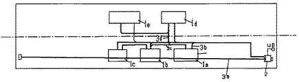
また、例えば図1に示すように、例えばモータ制御器、静止電源装置、ブレーキ制御機器、ドア開閉制御器などの各種機器1a、1b・・・・、端子台2間を中継なしで多数の配線ハーネスで配線しているため、一つの機器に方々の方向に位置する機器からの配線ハーネス3a、3b、3c・・・・がタコ足配線状に接続されることになる。このために、機器単位で一つのハーネスとして纏めることができず、配線ハーネスが混雑する場合が少なくない。
また、予め機器単位で一つの配線ハーネスとして纏めることができないので、現場でコネクタに追加結線している。
以上のような従来の鉄道車両の配線システムにおいては、配線のための予備作業に多くの手数を要し、車両本体への敷設、個々の配線ハーネスの機器への接続作業に多くの手数と時間を要する。このため配線作業コストが嵩んでいる。
【0003】
【解決しようとする課題】
この発明は、上記の従来技術の問題を解消することを目的とし、鉄道車両の配線ハーネスを配線するための予備作業を簡略にし、車両本体への敷設、個々の機器への接続作業を簡単、容易にするために、配線ハーネスを可及的にユニット化できるように、配線システムの構成を工夫することをその課題とするものである。
【0004】
【課題解決のために講じた手段】
上記課題解決のために講じた手段は、鉄道車両の床下、天井、側壁に配線された鉄道車両の配線システムを前提にして、次の要件(イ)乃至(ニ)によって構成されるものである。
(イ)複数本の配線ハーネスを一纏まりの主多心ケーブル24にした配線区間に主中継器21,22,23を介在させるものであること、
(ロ)上記主中継器21,22,23は、幹多心ケーブル25aとこの幹多心ケーブル25aから分岐させた枝分岐多心ケーブル25bとからなる多心分岐ケーブル25を有するものであること、
(ハ)上記主多心ケーブル24に、多心分岐ケーブル25の幹多心ケーブル25aを主中継器21,22,23の多心線コネクタ25cを介して接続したものであること、
(ニ)上記多心分岐ケーブル25の枝分岐多心ケーブル25bのコネクタ25dに、機器30a,30b,30c,30dのサブ中継器31a,31b,31c,31dに接続されたサブ多心ケーブル26,27を接続したことである。
【0005】
【作用】
個々の機器と中継器との間を多数の配線ハーネスで接続する作業は、現場作業であるが、機器と中継器間の配線ハーネスは短いから取扱いは簡単であり、また、中継器と近傍の機器間の接続作業であるからこの配線作業は簡単、容易である。
そして、上記の比較的短い配線ハーネスについての切断、コネクタの接続などの予備作業は、長い配線ハーネスについての予備作業に比して極めて簡単、容易である。
また、複数本の配線ハーネスを一纏まりの主多心ケーブルにした配線区間に、いくつかの主中継器を介在させ、その主多心ケーブルにした個々の心線のコネクタを主中継器のコネクタに接続することで、主中継器の幹多心ケーブルが多数の心線で互いに接続される。これによって、遠方の機器が幹多心ケーブル枝分岐多心ケーブル、サブ多心ケーブル、サブ主中継器、短い個々の配線ハーネスを介して接続される。上記それぞれの多心ケーブルの全ての心線の長さは等しいから、それぞれの多心ケーブルを所定の長さで切断し、その両端にコネクタを接続することで、配線用の主多心ケーブルを容易に準備することができる。
配線作業では、所定の位置に所定の中継器を取付け、個々の中継器を所定の多心ケーブルで接続し、中継器と各機器とを所要の配線ハーネスで接続する。
これによって、各機器が上記個々の配線ハーネスと中継器、多心ケーブルとによって互いに接続されることになる。
多心ケーブルを所定間隔で車体に固定するのは簡単、容易であるから、配線作業は簡略に行われる。
また、上記主中継器の幹多心ケーブルから分岐する枝分岐多心ケーブルからサブ多心ケーブルに分岐されるから、主中継器とサブ中継器をサブ多心ケーブルで接続し、サブ中継器と種々の機器を個々の配線ハーネスで接続することができる。
これによって長い多心ケーブルの心線数を少なくすることができるから、多心ケーブルを小径化、軽量化するとともに、その敷設作業を容易にすることができる。
また、上記幹多心ケーブルが枝分岐多心ケーブルを介して多数のサブ多心ケーブルに分岐されているから、個々のサブ多心ケーブルの先端をそれぞれに対応するサブ中継器に接続することで、一つの主中継器と多数のサブ中継器とをそれぞれ一つのサブ多心ケーブルで接続することができるから、必要な多心ケーブル数を少なくすることができる。したがって、多心ケーブルの敷設作業をより簡略にすることができる。
【0006】
【実施態様1】
実施態様1は、上記主中継器の一つのコネクタと他の複数のコネクタとを多心ケーブルから分岐した複数の分岐多心ケーブルでそれぞれ接続したことである。
【作用】
多心ケーブルの心線を中継器の上記一つのコネクタに接続し、上記他の複数のコネクタに個々の配線ハーネスを接続することで、多心ケーブルの心線を中継器で複数に分岐できる。したがって、多心ケーブルの心線数を少なくすることができるから、上記多心ケーブルを小径化し、軽量化できるとともに、その敷設作業を簡単、容易にすることができる。
【0007】
【実施態様2】
実施態様2は、上記主中継器を密閉型中継箱にし、この中継箱にコネクタを設けたことである。
【作用】
多心ケーブルのコネクタ、個々の配線ハーネスなどのコネクタが密閉型中継器箱内に集約して設けられ、これらのコネクタは中継箱によって防水されるので、配線のための防水機構が簡略化される。
【0008】
【実施態様3】
実施態様3は、上記主中継器を開放型中継器箱又は中継板にしたことである。
【作用】
この実施態様は防水を要しない配線について適したものであり、主中継器の構造を簡単にし、多心ケーブル、個々の配線ハーネスのコネクタの主中継器のコネクタへの接続、取外し作業を容易にすることができる。
【0009】
【実施例】
概念的に示した図2の実施例は、主中継器21,22,23を車体に固定し、主中継器21、主中継器22、主中継器23を主多心ケーブル24で接続している。主中継器21,22,23は、幹多心ケーブル25aと枝分岐多心ケーブル25とで構成された多心分岐ケーブル25を有しているものである。この幹多心ケーブル25aの両端と枝分岐多心ケーブル25bの先端にはそれぞれ多心線コネクタ25c、25dを設けている。
主多心ケーブル24の非防水コネクタ24aを上記幹多心ケーブル25aの多心線コネクタ25cに接続し、サブ多心ケーブル26,27のコネクタ26a、26aを枝分岐多心ケーブル25bの多心線コネクタ25dに嵌め込むことで、主多心ケーブル24、つまり、幹多心ケーブル25aから分岐する枝分岐多心ケーブル25bからサブ多心ケーブル26,27に分岐され、サブ多心ケーブル26,27の多心線のコネクタを機器30a、30bに設けられたサブ中継器31a、31bのコネクタ(図示省略)に接続されている。
この実施例においては、機器30a、30bのサブ中継器31a、31bの出力端子と機器30a、30bとの間には個々の配線ハーネスはないので、機器30a、30bの配線が上記出力端子にねじ止め、ハンダ付けなどで接続されている。
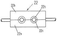
上記主中継器22,23は開閉可能な密閉箱型であり、中継箱本体22aと中継箱蓋体22bとの合わせ面にC形切り欠きがあり、このC形切り欠きの内面にC形パッキン22cがそれぞれ装着されている。中継器本体22aの上記C形切り欠きに主多心ケーブル24,24、サブ多心ケーブル26,27がそれぞれ嵌め込まれ、中継箱蓋体22bが閉じられたとき、中継箱本体22a、中継箱蓋体22bの上記C形パッキン22c、22cによって把持され、これによって上記主多心ケーブル24,サブ多心ケーブル26,27の貫通部がシールされる。
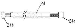
上記実施例の主中継器22、23は防水箱になっているので、上記主多心ケーブル24の一端に非防水コネクタ24aが設けられ、他端に防水コネクタ24bが設けられている(図5参照)。上記一端の非防水コネクタ24aが密閉箱型の主中継器22の幹多心ケーブル25aの端部に設けられた多心線コネクタ25cに接続され、他端の防水コネクタ24bが主中継器21のコネクタに接続されている。この実施例は、例えば、車両の走行停止装置の制御、また、側引き戸の開閉操作、側引き戸の開閉検知センサ、非常スイッチなどの、側引き戸関連の一連の配線に適用するのに適したものであり、また、機器30aをモータ制御器、機器30bを静止電源装置とし、機器30cをブレーキ制御器および各種ブレーキセンサとし、さらに機器30dを配電箱とするなど、系統の異なる複数の機器の配線(配線ハーネス)を一纏めにした状態で適用することもできる。
【0010】
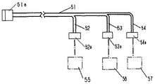
図6に示す多心ケーブル51は分岐型多心ケーブルであって、一端にコネクタ51aを設けた多心ケーブル51の他端が長さの異なる位置で3つに分岐された多心ケーブル52,53,54になっていて、これらの先端にそれぞれコネクタ52a、53a,54aが設けられており、これらがそれぞれ異なるサブ中継器55,56,57に接続されるものである。このものは車両の客室照明器、空調装置、空調ファン等の、車掌室から制御され、各車両の前後方向に一列に配置された機器用の配線等に適しているものである。
【0011】
図7(a)に示すものは、中継器による分岐の一例であって、中継器61に接続された多心ケーブル60の一本の心線を、中継器61で二つに分岐した例である。この例においては、中継器61の多心線コネクタ62の一つの接続端子に接続された配線63を当該中継器内で二つの配線63a、63bにそれぞれ分岐してあって、これらの配線63a、63bの他端にそれぞれコネクタ64a、64bがもうけられている。
そして、これらのコネクタ64a、64bにそれぞれ別の機器に接続された配線ハーネス65a、65bのコネクタ65cが接続せれている。
このような構造の中継器は分岐盤として機能することもできる。
【0012】
図7(b)、(c)の例は、中継器内での分岐の他の例、すなわち、4つに分岐する例、多数に分岐する例である。
【0013】
【発明の効果】
以上述べたとおり、この発明は、鉄道車両における配線ハーネスをできるだけ多くの配線ハーネスを纏めて一つの多心ケーブル化し、できるだけ長い範囲を多心ケーブルでカバーすることができるものであり、これによって、配線作業における配線ハーネスの切断、コネクタ取付け、配線ハーネス(個々の被覆線)の長さ調整、ハーネスの取り纏めなどの準備作業を簡略にすることができ、また、車両の配線ハーネスの大部分を多心ケーブルでカバーできるので、配線ハーネスの引き回し、整理整頓が極めて容易であり、これらの車両への敷設作業を簡略にすることができる。
したがって、配線材料、配線作業のコストを大幅に低減することができる。
また、断線補修、配線増設などに備えて予備の心線を多心ケーブルに予め組み込んで置くことができる(従来の配線方式では断線に備えて予備線を配線しておくことは、配線が錯綜している等のために大幅なコストアップになる)ので、断線などのためのメンテナンスが容易であり、また、配線増設作業を簡単、容易にすることができる。
【0013】
また、多心ケーブルが接続される中継器を分岐盤としても利用できるので、分岐盤として利用される中継器までの多心ケーブルの心線数を大幅に少なくすることができ、それだけ多心ケーブルを細径化することができる。
したがって、多心ケーブルの材料コストを低減できるとともに、多心ケーブル敷設作業におけるその取扱い、配線作業が簡単、容易になり、配線作業のコストを大幅に低減することができる。
【図面の簡単な説明】
【図1】は鉄道車両の配線の従来例の概念図である。
【図2】は実施例の概念図である。
【図3】は図2における中継器の内部を概略的に示す平面図である。
【図4】は図2における中継器の正面図である。
【図5】は図2の主多心ケーブルの平面図である。
【図6】は分岐型多心ケーブルの一例の概略的な平面図である。
【図7】(a)は中継器による分岐例の平面図であり、(b)は他の分岐例の平面図であり、(c)はさらに他の分岐例の平面図である。
【符号の説明】
21,22,23:主中継器
22a:中継箱本体
22b:中継箱蓋体
22c:C形パッキン
24:主多心ケーブル
24a:非防水コネクタ
24b:防水コネクタ
25:多心分岐ケーブル
25a:幹多心ケーブル
25b:枝分岐多心ケーブル
25c、25d:多心コネクタ
26,27:サブ多心ケーブル
26a:コネクタ
30a〜30d:機器
31a、31b:サブ中継器
51:多心ケーブル
52,53,54:分岐された多心ケーブル
55,56,57:サブ中継器
64a、64b:コネクタ
65a、65b:配線ハーネス
65c:コネクタ[0001]
[Industrial applications]
BACKGROUND OF THE INVENTION 1. Field of the Invention The present invention relates to a wiring system for a railway vehicle wired under a floor, a ceiling, and a side wall. Can be simplified and facilitated, and the cost of wiring work can be reduced.
[0002]
[Prior art]
A railway vehicle is equipped with a myriad of wiring harnesses (covered wires) that are long in the longitudinal direction, and wiring systems (wiring harnesses, repeaters, switchboards, etc., are used to supply power to railway vehicles, control signal transmission, detection signal transmission, etc. The wiring harness is configured in such a manner that a large number of wiring harnesses are cut in advance one by one at a predetermined length, and a predetermined connector is connected to both ends thereof. The parts requiring bundling and protection are covered with pipes, rubber tubes, and the like, and the bundle of wiring harnesses is fixed to a vehicle floor, a roof, or the like for each bundle at a predetermined interval with an appropriate fixing bracket.
Also, as shown in FIG. 1, for example, a large number of wirings without relay between
Further, since it is not possible to put together one wiring harness in advance for each device, an additional connection is made to the connector at the site.
In the conventional railway vehicle wiring system as described above, a lot of trouble is required for the preliminary work for wiring, and a lot of work and time are required for laying on the vehicle main body and connecting individual wiring harnesses to the equipment. Cost. For this reason, the wiring operation cost increases.
[0003]
[Problem to be solved]
The present invention has an object of solving the above-mentioned problems of the prior art, and simplifies a preliminary work for wiring a wiring harness of a railway vehicle, laying on a vehicle body, and simplifying a connection operation to individual devices. It is an object of the present invention to devise a configuration of a wiring system so that a wiring harness can be unitized as much as possible.
[0004]
[Measures taken to solve the problem]
Means taken to solve the above-mentioned problems are configured on the premise of a wiring system of a railway vehicle wired under the floor, ceiling, and side walls of the railway vehicle, and are configured by the following requirements (a) to (d). .
(A)
(B) The
(C) The trunk
(D) The sub-multi-
[0005]
[Action]
The work of connecting individual devices and repeaters with a number of wiring harnesses is an on-site work, but the wiring harness between the devices and the repeaters is short and easy to handle. This wiring work is simple and easy because it is a connection work between devices.
Preliminary work such as cutting and connection of a connector for the relatively short wiring harness is extremely simple and easy as compared with preliminary work for the long wiring harness.
In addition, several main repeaters are interposed in a wiring section where a plurality of wiring harnesses are grouped into a main multi-core cable, and the connectors of the individual cores formed as the main multi-core cables are connected to the main repeater connector. , The trunk multi-core cables of the main repeater are connected to each other by a number of core wires. As a result, remote devices are connected via trunk multi-core cable branch multi-core cables, sub multi-core cables, sub main repeaters, and short individual wiring harnesses. Since the lengths of all the core wires of the respective multi-core cables are equal, each multi-core cable is cut at a predetermined length, and connectors are connected to both ends thereof, so that a main multi-core cable for wiring is formed. Can be easily prepared.
In the wiring work, a predetermined repeater is mounted at a predetermined position, each repeater is connected with a predetermined multi-core cable, and the repeater and each device are connected with a required wiring harness.
Thereby, each device is connected to each other by the individual wiring harness, the repeater, and the multi-core cable.
Since it is easy and easy to fix the multi-core cable to the vehicle body at predetermined intervals, the wiring work is performed simply.
Also, since the branch multi-core cable branched from the trunk multi-core cable of the main repeater is branched into a sub multi-core cable, the main repeater and the sub repeater are connected by a sub multi-core cable, and Various devices can be connected by individual wiring harnesses.
As a result, the number of core wires of the long multi-core cable can be reduced, so that the diameter and weight of the multi-core cable can be reduced and the laying operation can be facilitated.
In addition, since the trunk multicore cable is branched into a number of submulticore cables via branch / branch multicore cables, by connecting the ends of the individual submulticore cables to the corresponding sub repeaters. Since one main repeater and a number of sub repeaters can be connected with one sub multi-core cable, the required number of multi-core cables can be reduced. Therefore, the work of laying the multi-core cable can be further simplified.
[0006]
Embodiment 1
In the first embodiment, one connector of the main repeater and a plurality of other connectors are respectively connected by a plurality of branched multi-core cables branched from the multi-core cable.
[Action]
By connecting the core of the multi-core cable to the one connector of the repeater and connecting the individual wiring harnesses to the other connectors, the core of the multi-core cable can be branched into a plurality of parts by the repeater. Therefore, since the number of core wires of the multi-core cable can be reduced, the diameter and the weight of the multi-core cable can be reduced, and the laying operation can be simplified and facilitated.
[0007]
Embodiment 2
Embodiment 2 is that the main repeater is a sealed relay box, and a connector is provided in the relay box.
[Action]
Connectors such as multi-core cable connectors and individual wiring harnesses are collectively provided in a sealed repeater box, and these connectors are waterproofed by the relay box, so that a waterproof mechanism for wiring is simplified. .
[0008]
[Action]
This embodiment is suitable for wiring that does not require waterproofing, simplifies the structure of the main repeater, and facilitates connection of multi-core cables, connectors of individual wiring harnesses to the connector of the main repeater, and removal work. can do.
[0009]
【Example】
In the conceptually illustrated embodiment of FIG. 2, the
The
In this embodiment, since there is no individual wiring harness between the output terminals of the
The
Since the
[0010]
The
[0011]
FIG. 7A shows an example of branching by the repeater, in which one core of the
The
The repeater having such a structure can also function as a switchboard.
[0012]
The examples of FIGS. 7B and 7C are other examples of branching in the repeater, that is, an example of branching into four and an example of branching into many.
[0013]
【The invention's effect】
As described above, the present invention makes it possible to combine as many wiring harnesses as possible into one multi-core cable, and cover the longest possible range with the multi-core cable. Preparation work such as cutting wiring harnesses, attaching connectors, adjusting the length of wiring harnesses (individually covered wires), unifying harnesses in wiring work, and simplifying most of the wiring harnesses for vehicles can be simplified. Since the wiring harness can be covered with the core cable, it is extremely easy to route and arrange the wiring harness, and the work of laying the wiring harness on the vehicle can be simplified.
Therefore, the cost of wiring material and wiring work can be significantly reduced.
In addition, a spare core wire can be incorporated in a multi-core cable in advance in preparation for wire breakage repair and additional wiring. (With the conventional wiring method, wiring a spare wire in preparation for wire breakage is complicated. This greatly increases the cost), so that maintenance for disconnection or the like is easy, and the work of adding wires can be made simple and easy.
[0013]
In addition, since the repeater to which the multi-core cable is connected can be used as a branch board, the number of multi-core cables to the repeater used as the branch board can be greatly reduced, and the multi-core cable can be reduced accordingly. Can be reduced in diameter.
Therefore, the material cost of the multi-core cable can be reduced, and the handling and wiring work in the multi-core cable laying work can be simplified and facilitated, and the wiring work cost can be greatly reduced.
[Brief description of the drawings]
FIG. 1 is a conceptual diagram of a conventional example of wiring of a railway vehicle.
FIG. 2 is a conceptual diagram of an embodiment.
FIG. 3 is a plan view schematically showing the inside of the repeater in FIG. 2;
FIG. 4 is a front view of the repeater in FIG. 2;
FIG. 5 is a plan view of the main multicore cable of FIG. 2;
FIG. 6 is a schematic plan view of an example of a branch type multi-core cable.
7A is a plan view of a branching example using a repeater, FIG. 7B is a plan view of another branching example, and FIG. 7C is a plan view of still another branching example.
[Explanation of symbols]
21, 22, 23:
Claims (4)
複数本の配線ハーネスを一纏まりの主多心ケーブル24にした配線区間に主中継器21,22,23を介在させ、
上記主中継器21,22,23は、幹多心ケーブル25aとこの幹多心ケーブル25aから分岐させた枝分岐多心ケーブル25bとからなる多心分岐ケーブル25を有するものであり、
上記主多心ケーブル24に、多心分岐ケーブル25の幹多心ケーブル25aを主中継器21,22,23の多心線コネクタ25cを介して接続し、
上記多心分岐ケーブル25の枝分岐多心ケーブル25bのコネクタ25dに、機器30a,30b,30c,30dのサブ中継器31a,31b,31c,31dに接続されたサブ多心ケーブル26,27を接続した鉄道車両の配線システム。In the wiring system of railway vehicles wired under the floor, ceiling, side walls,
Main repeaters 21, 22, 23 are interposed in a wiring section in which a plurality of wiring harnesses are grouped into a main multi-core cable 24,
The main repeaters 21, 22, and 23 have a multi-core branch cable 25 including a trunk multi-core cable 25a and a branch-branch multi-core cable 25b branched from the trunk multi-core cable 25a.
The trunk multi-core cable 25a of the multi-core branch cable 25 is connected to the main multi-core cable 24 via the multi-core connector 25c of the main repeaters 21, 22, 23,
The sub-multi-core cables 26 and 27 connected to the sub-repeaters 31a, 31b, 31c and 31d of the devices 30a, 30b, 30c and 30d are connected to the connector 25d of the branch-multi-core cable 25b of the multi-core branch cable 25. wiring system of the railway vehicle.
Priority Applications (1)
| Application Number | Priority Date | Filing Date | Title |
|---|---|---|---|
| JP2000126980A JP3570710B2 (en) | 2000-04-27 | 2000-04-27 | Railway vehicle wiring system |
Applications Claiming Priority (1)
| Application Number | Priority Date | Filing Date | Title |
|---|---|---|---|
| JP2000126980A JP3570710B2 (en) | 2000-04-27 | 2000-04-27 | Railway vehicle wiring system |
Publications (2)
| Publication Number | Publication Date |
|---|---|
| JP2001310735A JP2001310735A (en) | 2001-11-06 |
| JP3570710B2 true JP3570710B2 (en) | 2004-09-29 |
Family
ID=18636655
Family Applications (1)
| Application Number | Title | Priority Date | Filing Date |
|---|---|---|---|
| JP2000126980A Expired - Fee Related JP3570710B2 (en) | 2000-04-27 | 2000-04-27 | Railway vehicle wiring system |
Country Status (1)
| Country | Link |
|---|---|
| JP (1) | JP3570710B2 (en) |
Families Citing this family (1)
| Publication number | Priority date | Publication date | Assignee | Title |
|---|---|---|---|---|
| ITTO20010678A1 (en) | 2001-07-11 | 2003-01-11 | Campagnolo Srl | ELECTRONIC CONTROL GROUP USABLE ON BOARD A BICYCLE. |
-
2000
- 2000-04-27 JP JP2000126980A patent/JP3570710B2/en not_active Expired - Fee Related
Also Published As
| Publication number | Publication date |
|---|---|
| JP2001310735A (en) | 2001-11-06 |
Similar Documents
| Publication | Publication Date | Title |
|---|---|---|
| JPS62191251A (en) | Method and device for assembling wire harness | |
| CN116142104A (en) | Vehicle circuit body | |
| CA2234845A1 (en) | Electropneumatic brake cable system | |
| JP7180997B2 (en) | Wire harnesses, component modules for wire harnesses, and vehicle parts | |
| PT1077162E (en) | CABLE BEAM CIRCUIT CONFIGURATION METHOD AND CABLE BEAM | |
| JP3570710B2 (en) | Railway vehicle wiring system | |
| DE4427253A1 (en) | Central locking system for car | |
| WO2019049386A1 (en) | Railway vehicle floor structure | |
| JPH0571058U (en) | Car wiring structure | |
| JP2004149014A (en) | Wiring connection structure between vehicles | |
| AU2006231036B2 (en) | Electrical switchgear | |
| JPH0361275A (en) | Elevating path device for elevator | |
| JP4454277B2 (en) | Wiring and piping harness mounting structure | |
| JPH072462A (en) | Elevator controlling cable line | |
| JPH0438428Y2 (en) | ||
| ITTO20000086A1 (en) | WIRING FOR MOTOR VEHICLE DASHBOARDS. | |
| JPH05306080A (en) | Cable connecting device for elevator | |
| JPS6288636A (en) | Assembling structure for electronic controller of vehicle | |
| JP4346367B2 (en) | How to update the control panel | |
| JPH0152217B2 (en) | ||
| JPH08148037A (en) | Wire harness | |
| JPS6248835A (en) | Wiring system for vehicle | |
| JPS6248836A (en) | Wiring system for vehicle | |
| JPH0249304U (en) | ||
| JPH0858492A (en) | Wiring structure of automobile |
Legal Events
| Date | Code | Title | Description |
|---|---|---|---|
| TRDD | Decision of grant or rejection written | ||
| A01 | Written decision to grant a patent or to grant a registration (utility model) |
Free format text: JAPANESE INTERMEDIATE CODE: A01 Effective date: 20040621 |
|
| A61 | First payment of annual fees (during grant procedure) |
Free format text: JAPANESE INTERMEDIATE CODE: A61 Effective date: 20040621 |
|
| R150 | Certificate of patent or registration of utility model |
Free format text: JAPANESE INTERMEDIATE CODE: R150 |
|
| FPAY | Renewal fee payment (event date is renewal date of database) |
Free format text: PAYMENT UNTIL: 20080702 Year of fee payment: 4 |
|
| FPAY | Renewal fee payment (event date is renewal date of database) |
Free format text: PAYMENT UNTIL: 20090702 Year of fee payment: 5 |
|
| LAPS | Cancellation because of no payment of annual fees |