JP3567877B2 - Sensor device - Google Patents
Sensor device Download PDFInfo
- Publication number
- JP3567877B2 JP3567877B2 JP2000292396A JP2000292396A JP3567877B2 JP 3567877 B2 JP3567877 B2 JP 3567877B2 JP 2000292396 A JP2000292396 A JP 2000292396A JP 2000292396 A JP2000292396 A JP 2000292396A JP 3567877 B2 JP3567877 B2 JP 3567877B2
- Authority
- JP
- Japan
- Prior art keywords
- sensor chip
- case
- sensor
- terminal
- protruding portion
- Prior art date
- Legal status (The legal status is an assumption and is not a legal conclusion. Google has not performed a legal analysis and makes no representation as to the accuracy of the status listed.)
- Expired - Fee Related
Links
Images


Description
【0001】
【発明の属する技術分野】
本発明は、ケースに、検出部としてのセンサチップと該センサチップに対して信号を入出力するためのターミナルを配設し、センサチップとターミナルとをワイヤボンディングしてなるセンサ装置およびその製造方法に関する。
【0002】
【従来の技術】
従来、この種のセンサ装置としては、例えば特開平7−243926号公報に記載の圧力センサが提案されている。このものは、樹脂等よりなるケースと、このケースに搭載された検出部としてのセンサチップと、このセンサチップと外部とを電気的に接続するためにケースに埋設された複数個のターミナルとを備えている。
【0003】
そして、この圧力センサにおいては、これら複数個のターミナルを、ケースのうちセンサチップの搭載領域の周囲に突出させ、各々のターミナルの突出部の先端面とセンサチップとを、ワイヤボンディングにより形成されたワイヤにより結線している。
【0004】
【発明が解決しようとする課題】
ところで、上記公報では、ワイヤボンディング部の構成については具体的な検討はなされていない。そこで、本発明者等が上記圧力センサの構成に基づいて当該ワイヤボンディング部の構成について試作検討したところ、次のような問題が生じることがわかった。
【0005】
例えば、ターミナルとして、断面正方形もしくは断面円形の棒状のものを用いる場合、図8に示す様に、各々のターミナル212の突出部の先端面は、正方形(図8(a)参照)もしくは円形(図8(b)参照)となる。なお、図8中、214はセンサチップである。
【0006】
しかし、これらの場合、ターミナル212の剛性が比較的弱く、ワイヤボンディングの際、その超音波による振動(図8中の矢印Y1方向への振動)によってターミナル212の突出部が位置ずれを起こし、ワイヤ213とターミナル212との接合性が低下する恐れがある。
【0007】
そこで、本発明は上記問題に鑑み、ケースに、検出部としてのセンサチップと該センサチップに対して信号を入出力するためのターミナルとを配設し、センサチップとターミナルの先端部とをワイヤボンディングしてなるセンサ装置において、ワイヤボンディングの接合性を確保することを目的とする。
【0008】
【課題を解決するための手段】
上記目的を達成するため、請求項1記載の発明では、ケース(10)と、このケースに搭載された検出部としてのセンサチップ(20)と、センサチップと外部とを電気的に接続するためにケースに埋設された複数個のターミナル(12)とを備え、これら複数個のターミナルはケースのうちセンサチップの搭載領域の周囲に突出した突出部(12a)を有しており、各々の突出部の先端面とセンサチップとがワイヤボンディングにより形成されたワイヤ(13)により結線されてなるセンサ装置において、各々の突出部を、突出方向へ延び且つ当該突出方向と直交する断面が長方形である角柱形状をなすものとしたことを特徴としている。
【0009】
本発明によれば、各々の突出部を、突出方向へ延び且つ当該突出方向と直交する断面が長方形である角柱形状をなすものとしており、当該突出方向と直交する断面が正方形もしくは円形であるものと比べて、突出部の体積を大きくすることができるため、突出部の剛性を向上させることができる。
【0010】
そのため、センサチップとターミナルにおける突出部の先端部とをワイヤボンディングする際、その超音波による振動が加わっても、突出部が位置ずれを起こしにくくなる。従って、本発明によれば、ワイヤボンディングの接合性を確保することができる。
【0011】
また、センサチップは通常矩形のチップである場合が多いが、請求項2記載の発明によれば、センサチップ(20)を矩形とした場合に、各々の突出部(12a)を、その長方形断面における長辺がセンサチップの辺と平行となるように配置したことを特徴としている。それによれば、センサチップの周囲においてターミナルの突出部の配置スペースを極力小さくすることができ、センサ装置の小型化に有効である。
【0012】
また、請求項3記載の発明では、センサチップ(20)を矩形とした場合に、各々の突出部(12a)を、その長方形断面における短辺がセンサチップの辺と平行となるように配置したことを特徴としている。それによれば、短辺方向に比べて剛性の高い長辺方向をワイヤボンディングの振動方向と一致させることができるため、好ましい。
【0013】
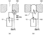
また、請求項1記載の発明では、突出部(12a)において、その先端面(120)と側面(121)とがなす角部(122)をテーパ形状としたことを特徴としている。ターミナル(12)をケース(10)に埋設するにあたっては、ターミナルをケースにインサート成形することが通常である。その場合、ケースから突出するターミナルの突出部は、成形型(100)の穴部(101)へ挿入された状態で成形される。
【0014】
従って、ケースから突出する突出部を形成するためには、ターミナルの先端部を成形型の穴部へ挿入する必要がある。この挿入において位置ずれが発生すると、突出部に相当するターミナルの先端部において、先端面と側面とがなす角部が当該穴部と干渉して、ターミナルの先端部が穴部へ挿入できない場合が起こりうる。
【0015】
その点、突出部において、その先端面と側面とがなす角部をテーパ形状とすることにより、挿入において多少の位置ずれが発生しても、このテーパ形状によりターミナルを成形型の穴部へ挿入することができる。
【0016】
また、ターミナルの突出部の側面の周囲には、ケースとターミナルとの隙間を封止するためのシール剤(14)が設けられる。このとき、シール剤のうち突出部の側面同士のなす角部に接している部位には、熱膨張等により応力が集中し、場合によってはこの集中した応力によりシール剤自身の破壊に至る恐れがある。
【0017】
その点、請求項4記載の発明のように、ターミナル(12)の突出部(12a)の側面(121)同士のなす角部(123)を、R形状とするかもしくは面取りした形状とすることにより、当該角部に接するシール剤(14)への応力集中を緩和することができるため、好ましい。
【0018】
また、ターミナルの突出部における先端面の平坦性や面粗度も、ワイヤとターミナルとの接合性においては重要な要因である。そこで、更に、突出部における先端面の平坦性や面粗度を向上させることで、ワイヤボンディングの接合性を向上させるべく検討を進めた。請求項5記載の発明は、この検討に基づいてなされたものである。
【0019】
即ち、請求項5記載の発明は、ケース(10)と、このケースに搭載された検出部としてのセンサチップ(20)と、センサチップと外部とを電気的に接続するためにケースに埋設された複数個のターミナル(12)とを備え、これら複数個のターミナルはケースのうち前記センサチップの搭載領域の周囲に突出した突出部(12a)を有しており、各々の突出部の先端面とセンサチップとがワイヤボンディングにより形成されたワイヤ(13)により結線されてなるセンサ装置を製造する方法であって、ターミナルにおける突出部の先端面と側面とがなす角部をテーパ形状とし、前記先端面をシェービング加工することにより平坦面とした後、突出部の先端面とセンサチップとをワイヤボンディングにより結線することを特徴としている。
【0020】
本製造方法によれば、ターミナルにおける突出部の先端面をシェービング加工して平坦面とすることにより、突出部における先端面の平坦性や面粗度を向上させることができるため、本発明の目的であるワイヤボンディングの接合性の確保が可能となる。また、突出部(12a)において、その先端面(120)と側面(121)とがなす角部(122)をテーパ形状としているので、請求項1に係る発明と同様、ターミナルの先端部を成形型の穴部へ挿入する際に、多少の位置ずれが発生しても、上記したテーパ形状によりターミナルを成形型の穴部へ挿入することができる。
【0021】
さらに、請求項6記載の製造方法によれば、ターミナル(12)における突出部(12a)の先端面を打ち抜き加工により形成し、前記角部をテーパ形状とした後、シェービング加工を行うことを特徴としている。それによれば、打ち抜き加工により突出部の先端面の大体の形状を形成することができるため、シェービング加工による当該先端面の切り代を少なくすることができる。そのため、シェービング加工における刃具の損傷防止、加工性の向上といった利点が得られる。
【0022】
また、請求項7記載の発明は、ケース(10)と、このケースに搭載された圧力検出用のセンサチップ(20)と、センサチップと外部とを電気的に接続するためにケースに埋設された複数個のターミナル(12)とを備え、これら複数個のターミナルはケースのうちセンサチップの搭載領域の周囲に突出した突出部(12a)を有しており、各々の突出部の先端面とセンサチップとがワイヤボンディングにより形成されたワイヤ(13)により結線されてなる圧力センサにおいて、各々の突出部を、突出方向へ延び且つ当該突出方向と直交する断面が長方形である角柱形状をなすものとし、さらに前記突出部において、その先端面と側面とがなす角部をテーパ形状としたことを特徴としている。
【0023】
本発明によれば、請求項1の発明と同様の作用効果を有する圧力センサを提供することができる。
【0024】
また、請求項8記載の圧力センサにおいては、ケース(10)にはその表面から凹んだ凹部(11)が形成されており、センサチップ(20)は凹部内に配設されており、突出部(12a)は凹部の底面から突出しており、凹部にはセンサチップ、突出部及びワイヤを覆うように圧力伝達媒体としてのオイル(41)が充填されていることを特徴としている。
【0025】
本発明の圧力センサによれば、突出方向と直交する断面が正方形もしくは円形である突出部と比べて、体積を大きくした長方形断面の突出部を有することにより、凹部内に占める突出部の体積を大きくすることができるため、オイルの充填量を低減することができる。
【0026】
また、上記請求項7及び請求項8に記載の圧力センサにおいて、上記請求項2〜請求項6に記載のセンサ装置の特徴部分を組み合わせたものとしても良い。
【0027】
なお、上記各手段の括弧内の符号は、後述する実施形態に記載の具体的手段との対応関係を示す一例である。
【0028】
【発明の実施の形態】
以下、本発明を図に示す実施形態について説明する。以下の各実施形態では、本発明のセンサ装置を圧力センサに具体化したものとして説明する。なお、各実施形態において同一部分には、図中、同一符号を付すことにより、各実施形態における説明を簡略化することとする。
【0029】
(第1実施形態)
図1は本実施形態に係る圧力センサS1の全体概略を示す断面図であり、この圧力センサS1は例えば自動車に搭載され自動車の燃料噴射系の燃料圧を検出するものに適用することができる。
【0030】
10はケース(コネクタケース)であり、本例では、このケース10は、PPS(ポリフェニレンサルファイド)やPBT(ポリブチレンテレフタレート)等の樹脂を型成形することにより作られ、略円柱状をなしている。このケース10の一端面(図1中、下方側の端面)には凹部11が形成されている。
【0031】
この凹部11には、圧力検出用の集積化センサ素子としてのセンサチップ(検出部)20が配設されている。本例のセンサチップ20は、受圧面としてのダイヤフラム(図示せず)を有し、受けた圧力を電気信号に変換しこの電気信号をセンサ信号として出力する半導体ダイヤフラム式のものである。そして、センサチップ20は、ガラス等よりなる台座21に陽極接合等により一体化されて、台座21を凹部11の底面に接着することで、ケース10に搭載されている。
【0032】
また、ケース10には、センサチップ20と外部の回路等とを電気的に接続するための複数個の金属製棒状のターミナル(コネクタピン)12が埋設されている。本例では、ターミナル12は黄銅(真鍮)にメッキ処理(例えばNiメッキ)を施した材料よりなり、インサートモールドによりケース10と一体に成形されることによりケース10内にて保持されている。
【0033】
各ターミナル12の一端側(図1中、下方端側)の端部は、センサチップ20の搭載領域の周囲において凹部11の底面から突出している。この突出した部分は、センサチップ20とワイヤボンディングが行われる突出部12aとして構成されている。
【0034】
ここで、各ターミナル12の突出部12aは、突出方向(図1中、下方)へ延び、且つ、当該突出方向と直交する断面が長方形である角柱形状をなしている。図2は、図1に示す圧力センサS1においてセンサチップ20及びターミナル12の突出部12aをセンサチップ20の受圧面(図1中、下方側の面)側から視た拡大平面図である。
【0035】
本例では、ターミナル12は、センサチップ20に形成された回路(図示せず)における信号出力用端子、接地端子(GND端子)、信号入力用端子、信号調整用端子の4個の端子に対応して4個設けられている。また、図2中、各突出部12aにおける突出方向(図2では紙面垂直方向)の先端面は、上記した長方形断面と対応した長方形として示されている。
【0036】
ちなみに、突出部12aにおける上記長方形断面のうち、長辺の長さL1、、短辺の長さL2(図2参照)は、それぞれ例えば2mm、0.8mmとすることができる。また、長辺の長さL1は短辺の長さL2の約2〜3倍程度とすることができる。
【0037】
なお、このようなターミナル12は、プレス加工で打ち抜き成形することで作ることができ、本例では、黄銅よりなる板材を所定形状に打ち抜き加工し、ターミナル12の最終形状を形成した後、メッキ処理することで形成することができる。このとき、上記板材としては、上記した長方形断面の短辺に相当する厚さのものを用いる方が、加工性の面から好ましい。そして、このターミナル12を成形型に設置し、樹脂成形を行うことにより、ターミナル12が埋設されたケース10が出来上がる。
【0038】
また、図2に示す様に、本例では、センサチップ20は平面矩形であり、各突出部12aは、その長方形断面(つまり先端面)における長辺がセンサチップ20の辺と平行となるように配置されている。そして、各突出部12aの先端面とセンサチップ20とは、金やアルミニウム等のワイヤボンディングにより形成されたワイヤ(ボンディングワイヤ)13を介して結線され電気的に接続されている。
【0039】
また、図1に示す様に、各突出部12aの側面の周囲には、ケース10とターミナル12との隙間を封止するためのシール剤14が設けられている。このシール剤14は例えばシリコン系樹脂よりなるもので、このシール剤14により、もし、突出部12aが突出する凹部11の底面部分に隙間があってもその隙間は封止される。
【0040】
一方、図1において、ケース10の他端側(図1中、上方端側)は、突出部12aとは反対側のターミナル12の他端側を例えばワイヤハーネス等の外部配線部材(図示せず)を介して上記外部回路(車両のECU等)に電気的に接続するための接続部15となっている。こうして、センサチップ20と外部との間の信号の伝達は、ワイヤ13及びターミナル12を介して行われるようになっている。
【0041】
次に、図1において、30はハウジングであり、例えばステンレス(SUS)等の金属材料よりなる本体部31を備える。この本体部31は、自動車の燃料タンクから燃料が導入される圧力導入孔32と、圧力センサS1を燃料配管等に固定するためのネジ部33とを有する。
【0042】
更に、ハウジング30は、薄い金属(例えばSUS等)製のシールダイヤフラム(メタルダイヤフラム)34と金属(例えばSUS等)製の押さえ部材(リングウェルド)35とが本体部31に全周溶接され、圧力導入孔32の一端に気密接合されたものとなっている。
【0043】
このハウジング30は、図1に示す様に、本体部31の端部36をケース10の一端側(図1中の下端側)にかしめることによりケース10と固定され一体化されている。こうして組み合わせられたケース10とハウジング30において、ケース10の凹部11とハウジング30のシールダイヤフラム34との間で、圧力検出室40が構成されている。
【0044】
この圧力検出室40には圧力伝達媒体であり封入液であるオイル(フッ素オイル等)41が充填され封入されている。このオイル41の封入により、凹部11にはセンサチップ20及びワイヤ13等の電気接続部分を覆うようにオイル41が充填され、更に、オイル41はシールダイヤフラム34により覆われて封止された形となる。
【0045】
また、圧力検出室40の外周囲には、環状の溝(Oリング溝)42が形成され、この溝42内には、圧力検出室40を気密封止するためのOリング43が配設されている。このOリング43は例えばシリコンゴム等の弾性材料よりなり、ケース10とハウジング30の押さえ部材35とにより挟まれて押圧されている。こうして、シールダイヤフラム34とOリング43とにより圧力検出室40が封止され閉塞されている。
【0046】
なお、本例では、上記溝42内には、Oリング43の外周にバックアップリング44が設けられている。このバックアップリング44は、例えば4フッ化エチレン樹脂等の樹脂材料よりなり、Oリング43が広がったときにOリング43がケース10と押さえ部材35との隙間に入り込んで損傷するのを防止する等の役割を担うものである。
【0047】
次に、上記圧力センサS1の製造方法について述べる。ターミナル12がインサート成形されたケース10を用意する。シリコン系樹脂等よりなる接着剤を用いて、ケース10の凹部11内へセンサチップ20を台座21を介し接着固定する。
【0048】
そして、凹部11内へシール剤14を注入し、シール剤14を各突出部12aの側面の周囲へ行き渡らせた後、硬化させる。次に、ワイヤボンディングを行って、各ターミナル12の突出部12aの先端面とセンサチップ20とをワイヤ13で結線する。
【0049】
そして、センサチップ20側を上にしてケース10を配置し、ケース10の上方から、ディスペンサ等によりフッ素オイル等よりなるオイル41を、凹部11へ一定量注入する。
【0050】
続いて、シールダイヤフラム34及び押さえ部材35が全周溶接され、圧力導入孔32の一端に気密接合されたハウジング30を用意し、このハウジング30を上から水平を保ったまま、ケース10に嵌合するように降ろす。この状態のものを真空室に入れて真空引きを行い圧力検出室40内の余分な空気を除去する。
【0051】
その後、ケース10とハウジング30の押さえ部材35とが十分接するまで押さえ、シールダイヤフラム34とOリング43によりシールされた圧力検出室40を形成する。次に、ハウジング30における本体部31の端部36をケース10の一端側にかしめることによりケース10と一体化する。こうして、ケース10とハウジング30との組合せ固定がなされ、図1に示す圧力センサS1が完成する。
【0052】
かかる圧力センサS1の基本的な圧力検出動作について述べる。圧力センサS1は、例えば、ハウジング30のネジ部33を介して、車両における燃料配管系の適所に取り付けられる。そして、該燃料配管内の燃料圧がハウジング30の圧力導入孔32より圧力センサS1内に導入される。
【0053】
すると、導入された燃料圧がシールダイヤフラム34から圧力検出室40内のオイル41を介して、センサチップ20の受圧面に印加される。そして、印加された圧力に応じた電気信号がセンサ信号として、センサチップ20から出力される。このセンサ信号は、センサチップ20からワイヤ13、ターミナル12を介して、上記外部回路へ伝達され、燃料配管の燃料圧が検出される。
【0054】
ところで、本実施形態によれば、各々のターミナル12の突出部12aを、突出方向へ延び且つ当該突出方向と直交する断面が長方形である角柱形状をなすものとしており、当該突出方向と直交する断面が正方形もしくは円形であるもの(上記図8参照)と比べて、突出部12aの体積を大きくすることができるため突出部12aの剛性を向上させることができる。
【0055】
センサチップ20と突出部12aの先端部とをワイヤボンディングする際、図2中の矢印Y1に示す様に、ワイヤ13の引き回し方向へワイヤボンディングの超音波による振動(例えば60kHz〜120kHz)が発生する。ここで、本実施形態では、突出部12aの剛性を十分大きく確保できるため、突出部12aが当該超音波振動による位置ずれを起こしにくくなる。従って、本実施形態によれば、ワイヤボンディングの接合性を確保することができる。
【0056】
また、本実施形態によれば、突出部12aの剛性を高めたことにより、突出部12aの周囲に設けられたシール剤14が、熱によって変形しても、このシール剤14の変形による突出部12aの変位を極力抑制することができる。それにより、ワイヤ13の接合部に加わる応力を低減することができる。
【0057】
また、本実施形態によれば、ケース10の凹部11には、該凹部11内のセンサチップ20、突出部12a、ワイヤ13及びシール剤14を覆うように圧力伝達媒体としてのオイル41が充填されている。このような構成において、突出部12aの体積を大きくしたことにより、凹部11内に占める突出部12aの体積を相対的に大きくすることができるため、オイル41の充填量を低減することができる。
【0058】
また、本例の圧力センサS1では、センサチップ20を矩形(図2参照)としており、各突出部12aを、その長方形断面における長辺がセンサチップ20の辺と平行となるように配置したことを特徴としている。それによれば、センサチップ20の周囲において、突出部12aの長方形断面における短辺の長さL2を考慮して配置スペースを決めれば良いため、ターミナル12の突出部12aの配置スペースを極力小さくすることができ、圧力センサの小型化に有効である。
【0059】
また、図2に示す例とは逆に、センサチップ20を矩形とした場合において、各突出部12aを、その長方形断面における短辺がセンサチップ20の辺と平行となるように配置しても良い。この例を図3に示す。図3中、矢印Y1は、ワイヤボンディングの超音波による振動方向を示す。
【0060】
それによれば、図2の配置例に比べて突出部12aの配置スペースは大きくなるけれども、短辺方向に比べて剛性の高い長辺方向をワイヤボンディングの振動方向と一致させることができるため、突出部12aの剛性を向上させターミナル12の位置ずれを抑制するという点からは好ましい。
【0061】
(第2実施形態)
本第2実施形態は、上記第1実施形態において、ターミナル12の突出部12aの形状を一部変形したものであり、上記第1実施形態と異なるところについて述べる。図4は、本実施形態に係る突出部12aの特徴を示す斜視図であり、(a)は上記第1実施形態の突出部12a、(b)は本第2実施形態の突出部12aを示す。
【0062】
図4(b)に示される突出部12aでは、図4(a)に示される突出部12aに比べて、その先端面120と側面121とがなす角部(先端角部)122をテーパ形状としたことを特徴としている。
【0063】
ターミナル12をケース10に埋設するにあたっては、上述したように、ターミナル12を成形型に設置し、樹脂成形を行うことにより、ターミナル12をケース10にインサート成形する。その場合、ケース10から突出するターミナル12の突出部12aは、成形型に設けられた穴部へ挿入された状態で成形される。従って、ケース10から突出する突出部12aを形成するためには、ターミナル12の先端部を成形型の穴部へ挿入する必要がある。
【0064】
図5は、ターミナル12の成形型100の穴部101への挿入の様子を示す説明図である。図5において、(a)は上記図4(a)に示すターミナル12を用いた場合、(b)は上記図4(b)に示すターミナル12を用いた場合を示している。
【0065】
図5(a)に示す例では、ターミナル12の挿入において図中の破線に示す様な位置ずれが発生すると、突出部12aに相当するターミナル12の先端部において、角部122が、穴部101の開口縁部と干渉する。ここで、成形型100における穴部101の開口縁部にも、ターミナル12の挿入性を向上させるべくテーパが設けられてはいるが、直角な角部122が当該開口縁部と干渉した場合、ターミナル12の先端部が穴部101へ挿入できない場合が起こりうる。
【0066】
その点、図5(b)に示す本実施形態のターミナル12によれば、突出部12aにおける角部122をテーパ形状とすることにより、図中の破線に示す様に、挿入において多少の位置ずれが発生しても、角部122のテーパ面が成形型100のテーパ面に沿ってすべっていくため、図中の一点鎖線に示す様に、ターミナル12の先端部を成形型100の穴部101へ挿入することができる。
【0067】
なお、図4(b)に示す様に、突出部12aの角部122にテーパを形成することは、図4(a)に示す状態の角部122を、例えばプレス加工等で押し潰して変形させることにより容易に実現できる。また、ターミナル12にメッキ処理を行う場合には、角部122にテーパを形成した後にメッキ処理を行う。
【0068】
(第3実施形態)
本第3実施形態は、上記第1実施形態において、ターミナル12の突出部12aの形状を一部変形したものであり、上記第1実施形態と異なるところについて述べる。図6は、本実施形態に係る突出部12aを示す斜視図である。本実施形態の突出部12aでは、その側面121同士のなす角部(側面角部)123を、R形状とするか(図6(a)参照)、もしくは、面取りした形状とした(図6(b)参照)ものである。
【0069】
上述したように、圧力センサS1においては、ターミナル12の突出部12aの側面の周囲に、ケース10とターミナル12との隙間を封止するためのシール剤14が設けられる。このとき、シール剤14のうち突出部12aの側面121同士のなす角部123に接している部位は、当該角部123の形状に対応した形状となる。
【0070】
もし、当該角部123が鋭角な形状である(上記図4(a)参照)と、当該角部123に接するシール剤14には、熱膨張等により応力が集中し、場合によっては、この集中した応力によりシール剤14自身の破壊に至る恐れがある。
【0071】
その点、図6に示す様に、ターミナル12の突出部12aの側面121同士のなす角部123を、R形状とするかもしくは面取りした形状とすることにより、当該角部123に接するシール剤14の形状も、R形状もしくは面取りした形状に対応した形状となる。それにより、当該角部123に接するシール剤14への応力集中を緩和することができる。
【0072】
なお、図6に示す様に、突出部12aの角部123をR形状もしくは面取り形状とすることは、当該角部123を、例えばプレス加工等で押し潰して変形させることにより容易に実現できる。また、ターミナル12にメッキ処理を行う場合には、角部123にR形状もしくは面取り形状を形成した後にメッキ処理を行う。また、本実施形態に対して、更に上記第2実施形態を組み合わせた構成としても良い。
【0073】
(第4実施形態)
また、ターミナル12の突出部12aにおける先端面の平坦性や面粗度も、ワイヤ13とターミナル12との接合性においては重要な要因である。本第4実施形態は、突出部12aにおける先端面の平坦性や面粗度を向上させることで、ワイヤボンディングの接合性を向上できるような圧力センサの製造方法を提供するものである。
【0074】
本実施形態の製造方法は、上記第1実施形態にて述べた圧力センサS1の製造方法を基本とし、ターミナル12の形成工程を変形したものである。よって、以下、主として上記第1実施形態とは異なる部分について述べることとする。図7は、本実施形態に係るターミナル12の形成方法を示す工程説明図である。
【0075】
上記第1実施形態にて述べたように、ターミナル12は、プレス加工で打ち抜き成形することで作ることができる。この場合、まず、図7(a)及び(b)に示す様に、打ち抜き用治具(パンチ)110を用いて、台111に固定されたターミナル用の板材112を打ち抜き加工し、ターミナル12の大体の形状を形成する。従って、この打ち抜き加工により突出部12aの先端面の大体の形状を形成することができる。
【0076】
しかし、この段階では、突出部12aの先端面(破断面)は、面粗度が粗かったり凹凸が存在するため、当該先端面の面粗度や平坦性は、ワイヤボンディングするためには未だ不十分な場合がある。そこで、次に、図7(c)及び(d)に示す様に、このターミナル12における突出部12aの先端面を、刃具113を用いてシェービング加工することにより平坦面とする。
【0077】
なお、本実施形態においても、上記第2及び第3実施形態を併用することが可能であるが、その場合、上記打ち抜き加工(図7(a)参照)を行い、角部へのテーパの形成や上記R形状、面取り形状の形成を行った後に、上記シェービング加工を行う。また、ターミナル12にメッキ処理を行う場合には、シェービング加工後に行う。
【0078】
その後、ターミナル12をインサート成形によりケース10に埋設し、突出部12aの先端面とセンサチップ20とをワイヤボンディングにより結線する。以上が本実施形態の製造方法の特徴部分であり、その他の製造工程は上記第1実施形態と同様に行い、圧力センサS1を製造することができる。
【0079】
以上述べた本実施形態の製造方法によれば、ターミナル12における突出部12aの先端面をシェービング加工して平坦面とすることにより、突出部12aにおける先端面の平坦性や面粗度を向上させることができるため、ワイヤボンディングの接合性を確保することができる。
【0080】
また、本製造方法では、ターミナル12における突出部12aの先端面を打ち抜き加工により形成した後、シェービング加工を行っている。それによれば、打ち抜き加工により、突出部12aの先端面の大体の形状を形成することができるため、シェービング加工による当該先端面の切り代を少なくすることができる。そのため、シェービング加工における刃具113の損傷防止、加工性の向上といった利点が得られる。
【0081】
なお、本実施形態では、ターミナル12を形成するにあたり、打ち抜き加工を行ってターミナル12の全体の大体形状を形成しているが、本例のようにターミナル12が棒状である場合、所定の長方形断面を持つ棒状素材を用意しておき、この棒状素材を、必要な長さに切断することによっても、ターミナル12を形成することができる。
【0082】
その場合、切断された棒状素材の切断面がターミナルの先端面となるが、例えば、棒状素材の切断をシェービング加工のみで行っても良い。つまり、図7(a)において、台112に上記棒状素材を固定し、打ち抜き治具110の代わりに上記刃具113を用いて、棒状素材を切断すれば、シェービング加工のみにより、平坦面となった突出部12aの先端面を形成することができる。
【0083】
(他の実施形態)
なお、本発明は、ケースと、このケースに搭載されたセンサチップと、ケースに埋設された複数個のターミナルとを備え、これら複数個のターミナルをケースのうちセンサチップの搭載領域の周囲に突出させ、各ターミナルの突出部の先端面とセンサチップとをワイヤボンディングにより結線してなるセンサ装置において、各々の突出部を、突出方向へ延び且つ当該突出方向と直交する断面が長方形である角柱形状をなすものとしたことを主たる特徴とするものであり、上記圧力センサ以外にも、加速度センサ、角速度センサ、磁気センサ、光センサ等のセンサ装置に適用しても良い。
【図面の簡単な説明】
【図1】本発明の第1実施形態に係る圧力センサの全体概略断面図である。
【図2】図1に示す圧力センサにおけるセンサチップとターミナルの突出部の詳細構成を示す部分拡大平面図である。
【図3】上記第1実施形態における突出部の配置構成の変形例を示す平面図である。
【図4】本発明の第2実施形態に係る突出部の特徴部分を示す斜視図である。
【図5】ターミナルの成形型への挿入の様子を示す説明図である。
【図6】本発明の第3実施形態に係る突出部を示す斜視図である。
【図7】本発明の第4実施形態に係るターミナルの形成方法を示す説明図である。
【図8】断面正方形もしくは断面円形の棒状のターミナルを用いて試作したセンサ装置のセンサチップ搭載領域周辺部を示す概略平面図である。
【符号の説明】
10…ケース、11…凹部、12…ターミナル、12a…突出部、13…ワイヤ、14…シール剤、20…センサチップ、41…オイル。[0001]
TECHNICAL FIELD OF THE INVENTION
The present invention provides a sensor device in which a case is provided with a sensor chip as a detection unit and a terminal for inputting and outputting a signal to and from the sensor chip, and the sensor chip and the terminal are wire-bonded, and a method of manufacturing the same. About.
[0002]
[Prior art]
Conventionally, as this type of sensor device, for example, a pressure sensor described in JP-A-7-243926 has been proposed. This is composed of a case made of resin or the like, a sensor chip as a detection unit mounted on the case, and a plurality of terminals buried in the case to electrically connect the sensor chip to the outside. Have.
[0003]
In this pressure sensor, these terminals protrude around the sensor chip mounting area of the case, and the tip surface of the protruding portion of each terminal and the sensor chip are formed by wire bonding. They are connected by wires.
[0004]
[Problems to be solved by the invention]
Incidentally, in the above publication, no specific study is made on the configuration of the wire bonding portion. Then, when the present inventors conducted trial manufacture and examined the configuration of the wire bonding portion based on the configuration of the pressure sensor, it was found that the following problems occurred.
[0005]
For example, when a rod-shaped terminal having a square cross section or a circular cross section is used as a terminal, as shown in FIG. 8, the distal end surface of the protruding portion of each
[0006]
However, in these cases, the rigidity of the
[0007]
In view of the above problem, the present invention provides a case in which a sensor chip as a detection unit and a terminal for inputting / outputting a signal to / from the sensor chip are provided, and a wire is connected between the sensor chip and the tip of the terminal. It is an object of the present invention to ensure the bondability of wire bonding in a sensor device formed by bonding.
[0008]
[Means for Solving the Problems]
In order to achieve the above object, according to the first aspect of the present invention, a case (10), a sensor chip (20) as a detection unit mounted on the case, and an electrical connection between the sensor chip and the outside. And a plurality of terminals (12) buried in the case, each of the plurality of terminals having a protruding portion (12a) protruding around the sensor chip mounting area of the case. In the sensor device in which the tip surface of the portion and the sensor chip are connected by a wire (13) formed by wire bonding, each projecting portion extends in the projecting direction and has a rectangular cross section orthogonal to the projecting direction. It is characterized by having a prismatic shape.
[0009]
According to the present invention, each protruding portion extends in the protruding direction and has a rectangular column shape in which a cross section orthogonal to the protruding direction is rectangular, and a cross section orthogonal to the protruding direction is square or circular. Since the volume of the protruding portion can be made larger than that of the protruding portion, the rigidity of the protruding portion can be improved.
[0010]
Therefore, when the sensor chip is wire-bonded to the distal end of the protruding portion of the terminal, the protruding portion is less likely to be displaced even if the ultrasonic vibration is applied. Therefore, according to the present invention, bondability of wire bonding can be ensured.
[0011]
Although the sensor chip is usually a rectangular chip in many cases, according to the second aspect of the present invention, when the sensor chip (20) is rectangular, each projection (12a) has a rectangular cross section. Are arranged so that the long side of the sensor chip is parallel to the side of the sensor chip. According to this, the arrangement space of the protruding portion of the terminal around the sensor chip can be made as small as possible, which is effective for downsizing the sensor device.
[0012]
According to the third aspect of the present invention, when the sensor chip (20) is rectangular, each protruding portion (12a) is arranged such that the short side in the rectangular cross section is parallel to the side of the sensor chip. It is characterized by: According to this, the long side direction having higher rigidity than the short side direction can be matched with the vibration direction of wire bonding, which is preferable.
[0013]
Claims1The described invention is characterized in that in the protruding portion (12a), a corner (122) formed by the tip surface (120) and the side surface (121) is tapered. In embedding the terminal (12) in the case (10), it is usual to insert-mold the terminal into the case. In this case, the protrusion of the terminal protruding from the case is molded in a state of being inserted into the hole (101) of the mold (100).
[0014]
Therefore, in order to form a projecting portion projecting from the case, it is necessary to insert the tip of the terminal into the hole of the mold. When a displacement occurs in this insertion, at the tip of the terminal corresponding to the protrusion, the corner formed by the tip surface and the side surface may interfere with the hole, and the tip of the terminal may not be inserted into the hole. It can happen.
[0015]
In this regard, in the protruding portion, by making the corner formed by the tip surface and the side surface into a tapered shape, even if a slight displacement occurs during insertion, the terminal is inserted into the hole of the molding die by this tapered shape. can do.
[0016]
A sealant (14) for sealing a gap between the case and the terminal is provided around the side surface of the projecting portion of the terminal. At this time, stress concentrates due to thermal expansion or the like in a portion of the sealant that is in contact with the corner formed by the side surfaces of the protruding portions, and in some cases, the concentrated stress may lead to destruction of the sealant itself. is there.
[0017]
That point, Claim4As in the invention described, the corner (123) formed between the side surfaces (121) of the protrusion (12a) of the terminal (12) is rounded or chamfered so that This is preferable because stress concentration on the sealing agent (14) in contact therewith can be reduced.
[0018]
In addition, the flatness and surface roughness of the tip surface at the protruding portion of the terminal are also important factors in the bondability between the wire and the terminal. Therefore, further studies have been made to improve the flatness and surface roughness of the front end surface of the protruding portion, thereby improving the bonding property of wire bonding. Claim5The described invention has been made based on this study.
[0019]
That is, the claims5The described invention provides a case (10), a sensor chip (20) as a detection unit mounted on the case, and a plurality of terminals embedded in the case to electrically connect the sensor chip to the outside. (12), and the plurality of terminals have protruding portions (12a) protruding around the mounting area of the sensor chip in the case, and the tip surface of each protruding portion and the sensor chip are connected to each other. A method of manufacturing a sensor device connected by wires (13) formed by wire bonding, comprising:The corner formed by the tip surface and the side surface is tapered,After shaving the front end surface to make it flat, the front end surface of the protruding portion and the sensor chip are connected by wire bonding.
[0020]
According to the present manufacturing method, by shaving the distal end surface of the protruding portion of the terminal into a flat surface, the flatness and surface roughness of the distal end surface of the protruding portion can be improved. , It is possible to ensure the bondability of wire bonding.Further, in the protruding portion (12a), the corner (122) formed by the front end surface (120) and the side surface (121) has a tapered shape, so that the front end of the terminal is formed similarly to the invention according to
[0021]
Claims6According to the manufacturing method described above, the distal end surface of the protruding portion (12a) of the terminal (12) is formed by punching., The corners are taperedAfter that, shaving is performed. According to this, since the approximate shape of the distal end surface of the protruding portion can be formed by the punching process, the cutting allowance of the distal end surface due to the shaving process can be reduced. Therefore, advantages such as prevention of damage to the cutting tool in shaving processing and improvement of workability can be obtained.
[0022]
Claims7The described invention provides a case (10), a sensor chip (20) for pressure detection mounted on the case, and a plurality of terminals embedded in the case for electrically connecting the sensor chip to the outside. (12), and the plurality of terminals have protruding portions (12a) protruding around the mounting area of the sensor chip in the case, and the distal end surface of each protruding portion and the sensor chip are connected by wires. In the pressure sensor connected by the wire (13) formed by bonding, each protruding portion has a prismatic shape extending in the protruding direction and having a rectangular cross section orthogonal to the protruding direction.Further, in the protruding portion, the corner formed by the tip surface and the side surface is tapered.It is characterized by:
[0023]
According to the present invention, it is possible to provide a pressure sensor having the same function and effect as the first aspect of the present invention.
[0024]
Claims8In the pressure sensor described above, the case (10) has a recess (11) recessed from the surface thereof, the sensor chip (20) is disposed in the recess, and the projection (12a) has a recess. , And the recess is filled with oil (41) as a pressure transmission medium so as to cover the sensor chip, the projection, and the wire.
[0025]
According to the pressure sensor of the present invention, since the cross section orthogonal to the protruding direction has a rectangular cross-sectional protruding portion having a larger volume than the protruding portion having a square or circular shape, the volume of the protruding portion occupying the recess is reduced Since the size can be increased, the filling amount of oil can be reduced.
[0026]
In addition, the above claims7And claims8The pressure sensor according to any one of
[0027]
It should be noted that reference numerals in parentheses of the above-described units are examples showing the correspondence with specific units described in the embodiments described later.
[0028]
BEST MODE FOR CARRYING OUT THE INVENTION
Hereinafter, embodiments of the present invention shown in the drawings will be described. In the following embodiments, a description will be given assuming that the sensor device of the present invention is embodied as a pressure sensor. Note that the same reference numerals in the drawings denote the same parts in each embodiment, and thus the description in each embodiment will be simplified.
[0029]
(1st Embodiment)
FIG. 1 is a cross-sectional view schematically showing the entirety of a pressure sensor S1 according to the present embodiment. This pressure sensor S1 can be applied to, for example, a sensor mounted on an automobile and detecting a fuel pressure of a fuel injection system of the automobile.
[0030]
[0031]
A sensor chip (detection unit) 20 as an integrated sensor element for pressure detection is provided in the
[0032]
A plurality of metal rod-shaped terminals (connector pins) 12 for electrically connecting the
[0033]
One end (the lower end in FIG. 1) of each terminal 12 protrudes from the bottom surface of the
[0034]
Here, the protruding
[0035]
In this example, the
[0036]
Incidentally, the length L1 of the long side and the length L2 (see FIG. 2) of the short side of the rectangular cross section of the protruding
[0037]
In addition, such a terminal 12 can be made by punching and forming by press working. In this example, a plate material made of brass is punched into a predetermined shape, and after forming a final shape of the terminal 12, a plating process is performed. Can be formed. At this time, it is preferable to use a plate having a thickness corresponding to the short side of the rectangular cross section from the viewpoint of workability. Then, the terminal 12 is placed in a molding die and resin molding is performed, whereby the
[0038]
Further, as shown in FIG. 2, in this example, the
[0039]
Further, as shown in FIG. 1, a
[0040]
On the other hand, in FIG. 1, the other end of the case 10 (the upper end in FIG. 1) is connected to the other end of the terminal 12 on the side opposite to the protruding
[0041]
Next, in FIG. 1,
[0042]
Further, in the
[0043]
As shown in FIG. 1, the
[0044]
The
[0045]
An annular groove (O-ring groove) 42 is formed around the
[0046]
In this example, a
[0047]
Next, a method for manufacturing the pressure sensor S1 will be described. The
[0048]
Then, the
[0049]
Then, the
[0050]
Subsequently, a
[0051]
Thereafter, the pressure is pressed until the
[0052]
A basic pressure detecting operation of the pressure sensor S1 will be described. The pressure sensor S1 is attached to an appropriate position of a fuel piping system in a vehicle, for example, via a
[0053]
Then, the introduced fuel pressure is applied from the
[0054]
By the way, according to the present embodiment, the protruding
[0055]
When the
[0056]
Further, according to the present embodiment, by increasing the rigidity of the
[0057]
Further, according to the present embodiment, the
[0058]
Further, in the pressure sensor S1 of the present example, the
[0059]
Also, contrary to the example shown in FIG. 2, when the
[0060]
According to this, although the arrangement space of the protruding
[0061]
(2nd Embodiment)
The second embodiment is obtained by partially modifying the shape of the protruding
[0062]
In the protruding
[0063]
In embedding the terminal 12 in the
[0064]
FIG. 5 is an explanatory view showing a state in which the terminal 12 is inserted into the
[0065]
In the example shown in FIG. 5A, when a positional shift as shown by a broken line in the drawing occurs during the insertion of the terminal 12, the
[0066]
In this regard, according to the
[0067]
In addition, as shown in FIG. 4B, forming the taper on the
[0068]
(Third embodiment)
The third embodiment is obtained by partially modifying the shape of the protruding
[0069]
As described above, in the pressure sensor S1, the
[0070]
If the
[0071]
In this regard, as shown in FIG. 6, by forming a
[0072]
In addition, as shown in FIG. 6, making the
[0073]
(Fourth embodiment)
In addition, the flatness and surface roughness of the distal end surface of the protruding
[0074]
The manufacturing method of the present embodiment is based on the manufacturing method of the pressure sensor S1 described in the first embodiment, and is a modification of the process of forming the terminal 12. Therefore, hereinafter, portions different from the first embodiment will be mainly described. FIG. 7 is a process explanatory view showing a method for forming the terminal 12 according to the present embodiment.
[0075]
As described in the first embodiment, the terminal 12 can be formed by punching and forming by press working. In this case, first, as shown in FIGS. 7A and 7B, a
[0076]
However, at this stage, the distal end surface (fracture surface) of the protruding
[0077]
In this embodiment, the second and third embodiments can be used together. In this case, the punching process (see FIG. 7A) is performed to form a taper at a corner. After forming the R shape and the chamfered shape, the shaving process is performed. When plating is performed on the terminal 12, the plating is performed after shaving.
[0078]
Thereafter, the terminal 12 is embedded in the
[0079]
According to the manufacturing method of the present embodiment described above, the flatness and surface roughness of the distal end surface of the protruding
[0080]
In the present manufacturing method, shaving is performed after the tip end surface of the protruding
[0081]
In the present embodiment, when forming the terminal 12, punching is performed to form a general shape of the
[0082]
In this case, the cut surface of the cut rod-shaped material becomes the tip end surface of the terminal. For example, the rod-shaped material may be cut only by shaving. That is, in FIG. 7A, when the bar-shaped material is fixed to the
[0083]
(Other embodiments)
The present invention includes a case, a sensor chip mounted on the case, and a plurality of terminals embedded in the case, and these terminals protrude around the sensor chip mounting area of the case. In the sensor device in which the tip surface of the protrusion of each terminal and the sensor chip are connected by wire bonding, each protrusion is formed in a prismatic shape extending in the protrusion direction and having a rectangular cross section orthogonal to the protrusion direction. The main feature of the present invention is that the present invention can be applied to sensor devices such as an acceleration sensor, an angular velocity sensor, a magnetic sensor, and an optical sensor in addition to the pressure sensor.
[Brief description of the drawings]
FIG. 1 is an overall schematic sectional view of a pressure sensor according to a first embodiment of the present invention.
FIG. 2 is a partially enlarged plan view showing a detailed configuration of a sensor chip and a protrusion of a terminal in the pressure sensor shown in FIG.
FIG. 3 is a plan view showing a modification of the arrangement of the protrusions in the first embodiment.
FIG. 4 is a perspective view showing a characteristic portion of a protrusion according to a second embodiment of the present invention.
FIG. 5 is an explanatory view showing how a terminal is inserted into a molding die.
FIG. 6 is a perspective view showing a protrusion according to a third embodiment of the present invention.
FIG. 7 is an explanatory view showing a method for forming a terminal according to a fourth embodiment of the present invention.
FIG. 8 is a schematic plan view showing the periphery of a sensor chip mounting region of a sensor device prototyped using a rod-shaped terminal having a square or circular cross section.
[Explanation of symbols]
DESCRIPTION OF
Claims (8)
このケースに搭載された検出部としてのセンサチップ(20)と、
前記センサチップと外部とを電気的に接続するために前記ケースに埋設された複数個のターミナル(12)とを備え、
これら複数個のターミナルは前記ケースのうち前記センサチップの搭載領域の周囲に突出した突出部(12a)を有しており、
各々の前記突出部の先端面と前記センサチップとが、ワイヤボンディングにより形成されたワイヤ(13)により結線されてなるセンサ装置において、
前記各々の突出部は、突出方向へ延び且つ当該突出方向と直交する断面が長方形である角柱形状をなすものであり、
前記突出部は、その先端面と側面とがなす角部がテーパ形状となっていることを特徴とするセンサ装置。Case (10),
A sensor chip (20) as a detection unit mounted on the case;
A plurality of terminals (12) embedded in the case for electrically connecting the sensor chip to the outside;
Each of the plurality of terminals has a protruding portion (12a) protruding around the mounting area of the sensor chip in the case,
In a sensor device, a tip surface of each of the protrusions and the sensor chip are connected by a wire (13) formed by wire bonding.
The projecting portion of the each state, and are not cross section and orthogonal to the protruding direction extending to the extended direction forms a prism shape is rectangular,
The sensor device according to claim 1, wherein the projecting portion has a tapered shape at a corner formed by a tip surface and a side surface .
前記各々の突出部(12a)は、その長方形断面における長辺が前記センサチップの辺と平行となるように配置されていることを特徴とする請求項1に記載のセンサ装置。The sensor chip (20) is rectangular;
The sensor device according to claim 1, wherein each of the protrusions (12a) is arranged such that a long side in a rectangular cross section thereof is parallel to a side of the sensor chip.
前記各々の突出部(12a)は、その長方形断面における短辺が前記センサチップの辺と平行となるように配置されていることを特徴とする請求項1に記載のセンサ装置。The sensor chip (20) is rectangular;
The sensor device according to claim 1, wherein each of the protrusions (12a) is arranged such that a short side in a rectangular cross section thereof is parallel to a side of the sensor chip.
このケースに搭載された検出部としてのセンサチップ(20)と、
前記センサチップと外部とを電気的に接続するために前記ケースに埋設された複数個のターミナル(12)とを備え、
これら複数個のターミナルは前記ケースのうち前記センサチップの搭載領域の周囲に突出した突出部(12a)を有しており、
各々の前記突出部の先端面と前記センサチップとが、ワイヤボンディングにより形成されたワイヤ(13)により結線されてなるセンサ装置において、
前記各々の突出部は、突出方向へ延び且つ当該突出方向と直交する断面が長方形である角柱形状をなすものであり、
前記突出部の側面の周囲には、前記ケースと前記ターミナルとの隙間を封止するためのシール剤(14)が設けられており、
前記突出部の前記側面同士のなす角部がR形状となっているかもしくは面取りされていることを特徴とするセンサ装置。 Case (10),
A sensor chip (20) as a detection unit mounted on the case;
A plurality of terminals (12) embedded in the case for electrically connecting the sensor chip to the outside;
Each of the plurality of terminals has a protruding portion (12a) protruding around the mounting area of the sensor chip in the case,
In a sensor device, a tip surface of each of the protrusions and the sensor chip are connected by a wire (13) formed by wire bonding.
Each of the projecting portions extends in the projecting direction and has a prismatic shape having a rectangular cross section orthogonal to the projecting direction,
Wherein the periphery of the side surface of the projecting portion is sealing agent (14) is provided for sealing the gap between the said casing terminal,
Sensor device angle portion of the side surfaces of the protrusion you characterized in that it is either or chamfered and has a R-shape.
このケースに搭載された検出部としてのセンサチップ(20)と、
前記センサチップと外部とを電気的に接続するために前記ケースに埋設された複数個のターミナル(12)とを備え、
これら複数個のターミナルは前記ケースのうち前記センサチップの搭載領域の周囲に突出した突出部(12a)を有しており、
各々の前記突出部の先端面と前記センサチップとが、ワイヤボンディングにより形成されたワイヤ(13)により結線されてなるセンサ装置を製造する方法であって、
前記ターミナルにおける前記突出部の先端面と側面とがなす角部をテーパ形状とし、前記先端面をシェービング加工することにより平坦面とした後、
前記突出部の先端面と前記センサチップとをワイヤボンディングにより結線することを特徴とするセンサ装置の製造方法。Case (10),
A sensor chip (20) as a detection unit mounted on the case;
A plurality of terminals (12) embedded in the case for electrically connecting the sensor chip to the outside;
Each of the plurality of terminals has a protruding portion (12a) protruding around the mounting area of the sensor chip in the case,
A method of manufacturing a sensor device in which a tip surface of each of the protrusions and the sensor chip are connected by a wire (13) formed by wire bonding,
After making the corner formed by the distal end surface and the side surface of the protruding portion in the terminal into a tapered shape, and shaping the distal end surface to a flat surface,
A method of manufacturing a sensor device, comprising: connecting a tip surface of the protruding portion to the sensor chip by wire bonding.
このケースに搭載された圧力検出用のセンサチップ(20)と、
前記センサチップと外部とを電気的に接続するために前記ケースに埋設された複数個のターミナル(12)とを備え、
これら複数個のターミナルは前記ケースのうち前記センサチップの搭載領域の周囲に突出した突出部(12a)を有しており、
各々の前記突出部の先端と前記センサチップとが、ワイヤボンディングにより形成されたワイヤ(13)により結線されてなる圧力センサにおいて、
前記各々の突出部は、突出方向へ延び且つ当該突出方向と直交する断面が長方形である角柱形状をなすものであり、
前記突出部は、その先端面と側面とがなす角部がテーパ形状となっていることを特徴とする圧力センサ。Case (10),
A sensor chip (20) for pressure detection mounted on the case;
A plurality of terminals (12) embedded in the case for electrically connecting the sensor chip to the outside;
Each of the plurality of terminals has a protruding portion (12a) protruding around the mounting area of the sensor chip in the case,
In a pressure sensor, a tip of each of the protrusions and the sensor chip are connected by a wire (13) formed by wire bonding.
The projecting portion of the each state, and are not cross section and orthogonal to the protruding direction extending to the extended direction forms a prism shape is rectangular,
The pressure sensor according to claim 1, wherein the protrusion has a tapered shape at a corner formed by a front end surface and a side surface .
前記センサチップ(20)は前記凹部内に配設されており、
前記突出部(12a)は前記凹部の底面から突出しており、
前記凹部には前記センサチップ、前記突出部及び前記ワイヤを覆うように圧力伝達媒体としてのオイル(41)が充填されていることを特徴とする請求項7に記載の圧力センサ。The case (10) has a recess (11) recessed from the surface thereof,
The sensor chip (20) is disposed in the recess;
The projecting portion (12a) projects from the bottom surface of the concave portion,
The pressure sensor according to claim 7 , wherein the recess is filled with oil (41) as a pressure transmission medium so as to cover the sensor chip, the protrusion, and the wire.
Priority Applications (2)
| Application Number | Priority Date | Filing Date | Title |
|---|---|---|---|
| JP2000292396A JP3567877B2 (en) | 2000-09-26 | 2000-09-26 | Sensor device |
| DE10147044.4A DE10147044B4 (en) | 2000-09-26 | 2001-09-25 | Pressure sensor with a detection element which is connected by a bonding wire to a terminal |
Applications Claiming Priority (1)
| Application Number | Priority Date | Filing Date | Title |
|---|---|---|---|
| JP2000292396A JP3567877B2 (en) | 2000-09-26 | 2000-09-26 | Sensor device |
Publications (2)
| Publication Number | Publication Date |
|---|---|
| JP2002098609A JP2002098609A (en) | 2002-04-05 |
| JP3567877B2 true JP3567877B2 (en) | 2004-09-22 |
Family
ID=18775346
Family Applications (1)
| Application Number | Title | Priority Date | Filing Date |
|---|---|---|---|
| JP2000292396A Expired - Fee Related JP3567877B2 (en) | 2000-09-26 | 2000-09-26 | Sensor device |
Country Status (1)
| Country | Link |
|---|---|
| JP (1) | JP3567877B2 (en) |
Cited By (2)
| Publication number | Priority date | Publication date | Assignee | Title |
|---|---|---|---|---|
| CN102818673B (en) * | 2012-05-05 | 2014-12-10 | 上海市计量测试技术研究院 | High-accuracy static extra high pressure sensor and pressure measurement method |
| JP2017528708A (en) * | 2014-08-25 | 2017-09-28 | メジャメント スペシャリティーズ, インコーポレイテッド | Freeze protection of pressure sensor |
Families Citing this family (2)
| Publication number | Priority date | Publication date | Assignee | Title |
|---|---|---|---|---|
| JP2011149895A (en) * | 2010-01-25 | 2011-08-04 | Yokogawa Electric Corp | Pressure measuring device |
| JP6315025B2 (en) | 2016-04-26 | 2018-04-25 | 株式会社デンソー | Physical quantity sensor and manufacturing method thereof |
-
2000
- 2000-09-26 JP JP2000292396A patent/JP3567877B2/en not_active Expired - Fee Related
Cited By (2)
| Publication number | Priority date | Publication date | Assignee | Title |
|---|---|---|---|---|
| CN102818673B (en) * | 2012-05-05 | 2014-12-10 | 上海市计量测试技术研究院 | High-accuracy static extra high pressure sensor and pressure measurement method |
| JP2017528708A (en) * | 2014-08-25 | 2017-09-28 | メジャメント スペシャリティーズ, インコーポレイテッド | Freeze protection of pressure sensor |
Also Published As
| Publication number | Publication date |
|---|---|
| JP2002098609A (en) | 2002-04-05 |
Similar Documents
| Publication | Publication Date | Title |
|---|---|---|
| US7213463B2 (en) | Pressure sensor having liquid in a pressure sensing chamber | |
| US7603908B2 (en) | Semiconductor pressure sensor, manufacturing method thereof, and die for molding semiconductor pressure sensor | |
| US7210357B2 (en) | Pressure sensor and manufacturing method of the same | |
| JP4301048B2 (en) | Pressure sensor and manufacturing method thereof | |
| US6678164B2 (en) | Pressure sensor and method for manufacturing the same | |
| JP4908411B2 (en) | Pressure sensor and manufacturing method thereof | |
| JP5278143B2 (en) | Pressure sensor | |
| US6619132B2 (en) | Sensor including a circuit lead frame and a terminal lead frame formed by a metal plate | |
| JP3567877B2 (en) | Sensor device | |
| JP3603772B2 (en) | Pressure sensor | |
| JP2003232693A (en) | Pressure sensor | |
| CN109311198B (en) | Synthetic resin molded article and method for producing same | |
| JP4497219B2 (en) | Pressure sensor and manufacturing method thereof | |
| JP3509627B2 (en) | Pressure detector | |
| JP2004132726A (en) | Pressure sensor | |
| JP3103526B2 (en) | Pressure sensor and method of manufacturing the same | |
| JP4622666B2 (en) | Electronic equipment | |
| JP4747922B2 (en) | Welding method | |
| JP3751528B2 (en) | Sensor and pressure sensor | |
| JP3835317B2 (en) | Pressure sensor | |
| JP2008111859A (en) | Semiconductor pressure sensor device | |
| JP2012093111A (en) | Sensor device | |
| JP2002228535A (en) | Pressure sensor | |
| JP2002131160A (en) | Sensor device | |
| JP6728980B2 (en) | Method of manufacturing pressure sensor |
Legal Events
| Date | Code | Title | Description |
|---|---|---|---|
| A977 | Report on retrieval |
Free format text: JAPANESE INTERMEDIATE CODE: A971007 Effective date: 20040219 |
|
| A131 | Notification of reasons for refusal |
Free format text: JAPANESE INTERMEDIATE CODE: A131 Effective date: 20040309 |
|
| A521 | Written amendment |
Free format text: JAPANESE INTERMEDIATE CODE: A523 Effective date: 20040423 |
|
| TRDD | Decision of grant or rejection written | ||
| A01 | Written decision to grant a patent or to grant a registration (utility model) |
Free format text: JAPANESE INTERMEDIATE CODE: A01 Effective date: 20040525 |
|
| A61 | First payment of annual fees (during grant procedure) |
Free format text: JAPANESE INTERMEDIATE CODE: A61 Effective date: 20040607 |
|
| R150 | Certificate of patent or registration of utility model |
Free format text: JAPANESE INTERMEDIATE CODE: R150 |
|
| FPAY | Renewal fee payment (event date is renewal date of database) |
Free format text: PAYMENT UNTIL: 20100625 Year of fee payment: 6 |
|
| FPAY | Renewal fee payment (event date is renewal date of database) |
Free format text: PAYMENT UNTIL: 20110625 Year of fee payment: 7 |
|
| FPAY | Renewal fee payment (event date is renewal date of database) |
Free format text: PAYMENT UNTIL: 20110625 Year of fee payment: 7 |
|
| FPAY | Renewal fee payment (event date is renewal date of database) |
Free format text: PAYMENT UNTIL: 20120625 Year of fee payment: 8 |
|
| FPAY | Renewal fee payment (event date is renewal date of database) |
Free format text: PAYMENT UNTIL: 20120625 Year of fee payment: 8 |
|
| FPAY | Renewal fee payment (event date is renewal date of database) |
Free format text: PAYMENT UNTIL: 20130625 Year of fee payment: 9 |
|
| FPAY | Renewal fee payment (event date is renewal date of database) |
Free format text: PAYMENT UNTIL: 20140625 Year of fee payment: 10 |
|
| R250 | Receipt of annual fees |
Free format text: JAPANESE INTERMEDIATE CODE: R250 |
|
| R250 | Receipt of annual fees |
Free format text: JAPANESE INTERMEDIATE CODE: R250 |
|
| R250 | Receipt of annual fees |
Free format text: JAPANESE INTERMEDIATE CODE: R250 |
|
| R250 | Receipt of annual fees |
Free format text: JAPANESE INTERMEDIATE CODE: R250 |
|
| LAPS | Cancellation because of no payment of annual fees |