JP3567331B2 - Fluid machinery - Google Patents
Fluid machinery Download PDFInfo
- Publication number
- JP3567331B2 JP3567331B2 JP23408893A JP23408893A JP3567331B2 JP 3567331 B2 JP3567331 B2 JP 3567331B2 JP 23408893 A JP23408893 A JP 23408893A JP 23408893 A JP23408893 A JP 23408893A JP 3567331 B2 JP3567331 B2 JP 3567331B2
- Authority
- JP
- Japan
- Prior art keywords
- piston
- discharge
- magnetic
- pipe
- pressure
- Prior art date
- Legal status (The legal status is an assumption and is not a legal conclusion. Google has not performed a legal analysis and makes no representation as to the accuracy of the status listed.)
- Expired - Lifetime
Links
Images


Landscapes
- Electromagnetic Pumps, Or The Like (AREA)
- Reciprocating Pumps (AREA)
Description
【0001】
【産業上の利用分野】
本発明は圧縮機、膨張機若しくは圧送機として適用される流体機械に係り、特に容積変化を行わしめるピストンに連設棒や駆動軸を直接連結させる事なく間接的に前記ピストンに駆動力を付与し、圧縮若しくは膨脹を行わしめる流体機械と、該流体機械において吐出圧の最適制御を可能ならしめた装置に関する。
【0002】
【従来の技術】
従来より往復動圧縮機はクランク軸の回転を連設棒を介してピストンの往復運動に変換してピストンとシリンダ間の容積変化により圧縮を行い、又可変翼やスクリュータイプの回転圧縮機においては、これらの可変翼やスクリューをモータに連結した駆動軸に連結し、該駆動軸の回転により可変翼やスクリューとケーシングとの間に形成される容積を変化させながら圧縮を行うように構成されている。
【0003】
この種の装置においては、駆動軸や連設棒等の駆動系と圧縮系が直接接続する構成を取るために、両者間にピストンリングやオイルシール等の圧縮漏洩阻止部材を介在させなければならず、その分部品点数や重量負担の増加、若しくはこれらの負荷に比例して消費電力の増大等につながり、結果として投入エネルギ当りの圧縮効率の低下につながる。
【0004】
かかる欠点を解消するために、ピストンの駆動機構を電磁ソレノイドによる直線的な駆動方式を採用した往復駆動圧縮機が種々提案されている。(特開昭61−210576、同60−116883等)
又特開平1−87879号においては超伝導体と磁石を利用して直線変位運動を発生させ、ピストンの往復運動を行うようにした圧縮機も提案されている。
これらの技術はいずれもピストン側に電磁的駆動力の反作用力としてコイルバネ等を介在させる構成を取り、圧縮行程においては電磁的駆動力による作用力を、吸入行程ではコイルバネによる反作用力を夫々利用して往復運動を行うように構成している。
【0005】
【発明が解決しようとする課題】
しかしながらこれらの技術はいずれも直線的な往復運動であるために、而も作用力(往動)から反作用力(復動)への移行をコイルバネによる弾性力により行っている為に基本的に高速駆動が不可能であり、その分重量若しくは容積当りの吐出量の増大を図る事が不可能である。
又前記技術では圧縮行程の上死点に近付くに連れ、コイルバネによる弾性力を受けるために、圧縮比を高める事が困難である。
又ピストン側に電磁的駆動力の反作用力としてコイルバネ等を介在させる構成を取る事は、コイルバネのへたり等があり、必ずしも長期的に安定した圧縮機を得るのが困難である。
【0006】
本発明者はかかる技術的課題に鑑み、コイルバネを併用する事なく電磁力のみでピストンを間接駆動可能に構成した、圧縮機若しくは膨張機、更にはポンプとして適用し得る流体機械を提供する為に、管壁の適宜箇所に流体吸入部と吐出部を設けた無端状管路内に、複数のフリーピストンを配し、該ピストンを外部よりの電磁力を利用して間接的に管路内を周回させつつ、前記吸入口と吐出口の位置に対応させて先行するピストンとの比速度を変化させて、該先行するピストンとの間に形成される閉鎖空間を変化させ、前記吸入部と吐出部との組合わせによって吸入行程−圧縮若しくは膨脹更には圧送行程−吐出行程が繰り返し行なわれる事を特徴とする流体機械を同時出願の特許願(整理番号P9364MA)において提案している。
本発明はかかる流体機械を実施するために好適な装置を提供する事を目的とする。
【0007】
【課題を解決する為の手段】
本発明は、前記管路をリング円状に形成し、該管路内のピストンを外部よりの磁力を利用して周回可能に構成した流体機械に適用されるもので、
前記ピストンに磁気的保持力を維持した状態で回転する磁性回転手段の回転中心を、前記管路中心に対し偏心した位置に設定し、該回転手段の回転により前記ピストンが前記回転中心の半径方向に揺動する自由度を維持した状態で前記管路内を周回可能に構成した事を要旨とするものである。
この場合前記磁性回転手段は、該回転手段の回転中心側より放射状に延びる磁性羽根体を前記ピストンと対応する数だけ配設し、該羽根体の回転に追従して前記ピストンが前記回転中心の半径方向に揺動しながら前記管路内を周回可能に構成するのがよい。
又前記磁性回転手段は前記ピストンの両側に対称に配置し、該ピストンを管路内に実質的に浮き状態で周回可能に構成する事により、ピストンと管路間で不要な摺擦が生じる事なく、又ピストンが管路一方の側に偏在する事もない為に圧力漏洩が生ぜず、特に無給油圧縮機に有利である。
【0008】
本第2発明は特に前記同時出願の基本発明全てに適用されるもので、前記管路をリング円状に形成しもののみならず無端状管路全てに、又ピストンの駆動力も磁力のみならず、電磁誘導を利用したものにも適用されるもので、特に最適な吐出圧を自動的に調整するVi自動可変装置を組込んだ流体機械を提供する事を目的とし、その特徴とするところは、前記吐出部の吐出開口を可変可能な開口可変手段を設け、該可変手段が吐出圧力と吐出口直前の容積空間圧力との平衡をとりながら移動可能に構成し、特に前記可変手段は、吐出口直前の管路壁の一部を形成するスライド弁であり、該スライド弁に、スライド弁の吐出圧の受圧断面積より大きい断面積を有するピストンを連結し、前記ピストンに吐出口直前の容積空間圧力を受圧可能に構成することにより達成し得る。
これにより圧縮過程による圧縮過多あるいは圧縮不足による動力損失の増加の防止を内圧によって最適な吐出圧を自動的に調整する事が出来る。
【0009】
尚、本発明に類似する技術として実開昭4ー119371号が存在する。
かかる考案は円形シリンダ内に複数のピストンを内蔵し、ソレノイドをシリンダ外周に複数配置し、リニアでピストンのみを緩急回転させ、吸入、圧縮する圧縮機等を提案している。
しかしながら前記従来技術においてはソレノイドを用いてピストンをどの様に緩急回転されるか開示されておらず、特にソレノイドのON/OFF駆動ではピストンが断続的に駆動され、先行するピストンとの比速度を変化させながら連続的に周回させる事は不可能である。
これに対し本発明は、前記ピストンに磁気的保持力を維持した状態で回転する磁性回転手段の回転中心を、前記管路中心に対し偏心した位置に設定し、該回転手段の回転により前記ピストンが前記回転中心の半径方向に揺動する自由度を維持した状態で前記管路内を周回可能に構成した為に、先行するピストンとの比速度を変化させながら連続的に周回させる事が可能であり、これにより始めて本発明が円滑に達成される。
【0010】
【実施例】
以下、図面に基づいて本発明の実施例を例示的に詳しく説明する。但しこの実施例に記載されている構成部品の寸法、材質、形状、その相対配置などは特に特定的な記載がない限りは、この発明の範囲をそれのみに限定する趣旨ではなく単なる説明例に過ぎない。
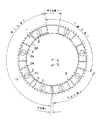
先ず本発明の基本構成を図1に基づいて説明する。先ずケーシング11のリング状円形管路1内に、該管路1内形状に酷似しかつ管路1に対し周囲微小クリアランスを有するフリーピストン2を複数個(2個以上)配置する。
そして各フリーピストン2は管路1外部からの力例えば(回転)磁場のような間接的な力によって浮されるとともに管路1内を所定の位置で所定の速度で動くように構成する。
例えば前記フリーピストン2には夫々磁性体若しくは磁石体(S極)3を内蔵し、外部よりの磁石体(N極)若しくは磁性体4の回転運動により前記フリーピストン2が回転するように構成する。
この際外部の磁性体4の回転中心Dを管路中心Cよりずらす事により、後記するように、先行するフリーピストン2と本フリーピストン2との比速度を変化させる事が出来る。
従って本フリーピストン2を先行するフリーピストン2の比速度が1以上になる行程では、本フリーピストン2前面と先行するフリーピストン2の背面及び管路1の壁によって形成される容積(以下、空間容積5)が順次広くなり、又比速度が1以下になる行程では、前記空間容積5が順次狭くなる。
そして前記管路1は無端状である為に、図1に示すように前記空間容積5が最大となる区域(最大容積区域d)と最小となる区域(死容積e)を挟んで比速度が1以下になる行程と、比速度が1以上になる行程とがほぼ半回転単位で交互に表れる事になる。
【0011】
図4(A)は前記ピストン2の回転角と先行ピストンと後行ピストン夫々の比速度を各ピストンの速度周期として表わしたもの、(B)は回転角と先行ピストンと後行ピストン間の比速度(先行ピストン速度と後行ピストン速度の比)をピストン間比速度として表わしたもの、(C)は回転角と空間容積5の変化を空間中心を基準として容積比で表わしたもの、の夫々のグラフである。
従って図1に示すように、比速度が1以上になる行程に吸入部を設けて吸入行程aとし、比速度が1以下になる行程に吸入部も吐出部も設けない管路1閉鎖空間としての圧縮行程bとし、吐出部を設けた吐出行程c部分にわけることにより、前記機構を圧縮機に適用し得る。
尚、図4(D)はかかる行程を主軸回転角度と圧力比との関係をグラフ化したもので、本図より理解できるように圧縮行程b部分と吐出行程c部分の比を適宜変化させる事により、圧縮比を任意に設定できる。
【0012】
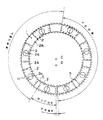
尚、図2は前記機構を非圧縮性の液ポンプとして適用したもので、基本的には圧縮行程が存在せずに最大容積dと死容積eを挟んで上流側が吸入行程a、下流側が圧送(吐出行程)bとなる。
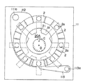
又、図3は前記機構を膨張機として適用したもので、最大容積d部分が膨張行程bとして拡大し、死容積eの次に、吸入行程a、膨張行程b、吐出行程cを設ける。
そして本発明を図1に基づいてより具体的に説明すると、吸入行程aでは(吸入ポートの開口範囲)では図2から明らかなように比速度がピストン2が回転方向に従って1以上に順次大きくなるとともに、これに比例して空間容積5が漸次大きくなり、吸入部より最大容積量のガスを吸入する事が出来る。
そして圧縮行程ではピストン2が回転方向に進行するにつれ比速度が1以下に順次小さくなり、これに比例して空間容積もは漸次小さくなり、吐出部まで所定の空間容積5の縮小を行なう。図4(D)では該圧縮行程に対応する圧力変化を示しこれにより前記圧縮行程bで所定の圧力比まで昇圧する事が理解できる。
そして吐出行程cではさらにピストン2の比速度を小さくすることにより、空間容積5が小さくなりはぼ0になることによって圧縮したガスを吐出口より円滑に排出出来る。
従って本発明は前記管路1が無端状、即ちリング状に形成されているために、吸入−圧縮−吐出行程を連続的且つ繰り返し行なう事が出来る。
尚、ピストン2の数は1回転あたりの容量の大小によって任意に設定すればよい。
【0013】
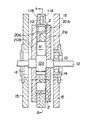
図5乃至図7は本発明の実施例たる圧縮機を示し、
図5は図6のAーA線断面図、図6は圧縮機本体10の縦断面図、図7は該本体をモータに組み付けた直結型圧縮機である。
図4において11は樹脂体若しくは非磁性金属、更にはグラファイト等で形成されたケーシングで、中央位置より僅かに上方に片寄せた位置に円形穴111を形成した2枚のケーシング板11A、11Bを重合させて形成されており、その重ね合わせ部の面上にC点を中心にリング円状の管路1、該管路1の吸入行程に対応する位置に吸入ポート112、及び吐出行程の死容積に近接する位置に吐出ポート113を夫々形成し、そして該ポート112、113は夫々後記する磁性板20の回転空間から外れた位置に、夫々吐出穴113aと吸気穴112aを設ける。
そして前記リング状円形管路1内に、該管路1内形状に酷似しかつ管路1に対し周囲微小クリアランスを有する弧状片からなるフリーピストン2を8個配置する。
該フリーピストン2は例えばグラファイト等の摺動性のよい材料で形成され、内部に円筒状の磁性体若しくは磁石体2a(S極)を埋設する。
そして前記ケーシング11の両側には、管路1中心の前記C点より垂直下方に所定距離ずらした位置に回転中心Dを有する回転軸12に回転可能に支承された一対の磁性板20A、20Bが配設されている。
磁性板20A、20Bは前記回転軸12中心より放射状に伸びる複数の羽根体21を有し、該羽根体21は前記フリーピストン2と対応する数だけ、等角度(45°)間隔に8本で延在させ、前記フリーピストン2と逆極性(N極)の磁石で形成するか若しくは前記フリーピストン2の内蔵磁性体が磁石体2aの場合は鉄その他の磁性材で形成する。
そして前記磁性板20A、20Bは回転軸12に設けたスペーサ部12aを利用して前記ケーシング11壁面に対し、微少クリアランスを保ちつつ、該ケーシング11を挟み込むように組立てる。尚、図6に示すようにピストン2が半径方向に移動する領域のみを磁石体で形成しても良い。
回転軸12は軸受14を介して支持枠15に両端支持され、そして図6に示すように、前記回転軸12の一端をカップリング16を介してモータ17に直結させている。
尚、図6中の18はモータ支持枠19と圧縮機本体10を固定する取付けネジで、圧縮機本体10側の軸受支持枠15とケーシング11間をもスペーサ19を介して一体的に連結させている。
【0014】
かかる実施例によれば、円筒状の内蔵磁石体2aを埋設したフリーピストン2はその両側に位置する磁性板20A、20Bの羽根体21により、磁性的に挟持されている為に、フリーピストン2は内蔵磁石体2aと磁性板20の羽根体21との間での発生する磁力によって羽根体21の延在方向と対応する所定の位置にて管路1内で管路1壁とのクリアランスを持って浮いてる状態になる。
そして前記両者間で発生した磁力は羽根体21に沿った半径方向には自由度があり又図4に示すように回転軸12中心と管路1中心が変位しているために、前記回転軸12を回転させると、フリーピストン2が管路に周方向規制されながら羽根体21に沿って半径方向に移動しつつ、フリーピストン2の管路1内での回転曲率がみかけ上変化させる事が出来る。
それによって前記したように吸入行程aでは比速度が1以上に漸次大きくなり効率良く吸入する事が出来る。
又吸入行程a通過後圧縮行程bでは比速度が1以下で漸次空間容積5が小さくなり、所定の圧縮が行われつつ所定の容積比の圧縮比を得る事が出来る。
そして吐出行程cでは比速度が更に小さくなりはぼ空間容積5が0になった状態で吐出ポート113よりの吐出を完了する。
【0015】
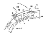
図8は、Vi自動可変装置を組込んだ他の実施例で、同図に基づいてその詳細を説明する。
31は吐出口直前の管路壁の一部を形成するスライド弁で、該スライド弁31のスライド位置によって吐出ポート113の吐出開始点、言い換えれば吐出開口容積が可変する。
そして前記スライド弁31は、連結棒32を介してピストン33に連結されている。
ピストン33は、吐出開口113直前のフリーピストン2間に形成される容積空間5A圧力Po’を受圧可能に、該容積空間5Aと連通管34で連絡されたシリンダ35内に収納されており、そして該ピストン33の受圧断面積をピストン33及びスライド弁31のフリクション及びスライド弁31前後の差圧による抵抗力に十分打ち勝つ断面積に設定している。
かかる実施例によれば、例えば吐出圧Poが高くなったときには容積空間圧力Po’との差圧(Po−Po′)が大きくなりピストン33はシリンダ34の背圧空間側に摺動する。一方スライド弁31は前記ピストン33の移動に追従して吐出側に動く事によって吐出開始点遅れが生じこの結果前記フリーピストン2ー2間の空間容積が小さくなって、言い換えれば空間容積5A内圧が上昇し、Po′=Poになるところまでスライド弁31が移動する。
一方吐出圧Poが低い場合は前記と逆の動作をする。
この結果図9に示すように本流体機械の圧縮過程による圧縮過多あるいは圧縮不足による動力損失の増加の防止を内圧によって最適な吐出圧を自動的に調整する事が出来る。
従ってかかる実施例によればいずれも前記した本発明の作用が円滑に達成し得る。
【0016】
【効果】
以上記載のごとく、本発明によれば、無端状管路内を複数のフリーピストンが周回する事により圧縮若しくは膨脹が行われる流体機械の最も好適な装置が提供できると共に、特に請求項4記載の発明においては、圧縮過程による圧縮過多あるいは圧縮不足による動力損失の増加阻止を有効に図れる。
等の種々の著効を有す。
又本実施例は圧縮機を例示して説明したが、前記説明より容易に理解されるごとく膨張機としても又液体圧送ポンプとしても適用可能である事は当業者ならば容易に理解できる。
【図面の簡単な説明】
【図1】本発明の基本構成図で圧縮機に適用した場合を示す。
【図2】本発明の基本構成図で液ポンプ機に適用した場合を示す。
【図3】本発明の基本構成図で膨張機に適用した場合を示す。
【図4】図4(A)は図1のピストンの回転角と先行ピストンと後行ピストン夫々の比速度を各ピストンの速度周期として表わしたもの、(B)は回転角と先行ピストンと後行ピストン間の比速度をピストン間比速度として表わしたもの、(C)は回転角と空間容積5の変化を空間中心を基準として容積比で表わしたもの、図4(D)は主軸回転角度と圧力比との関係をグラフ化したものである。
【図5】図5乃至図7は本発明を実施するための具体例で、図5は図6のAーA線断面図である。
【図6】本発明の実施例にかかる圧縮機本体の縦断面図である。
【図7】図6の本体をモータに組み付けた直結型圧縮機である。
【図8】圧縮過程による圧縮過多あるいは圧縮不足による動力損失の増加の防止を内圧によって最適な吐出圧を自動的に調整する事が出来るVi自動可変装置を組込んだ他の実施例を示す。
【図9】図8の動力損失を示すグラフ図。
【符号の説明】
112 吸入部
113 吐出部
1 無端状管路
2 フリーピストン
5、5A 空間容積
31 スライド弁
32 連結棒
33 ピストン[0001]
[Industrial applications]
The present invention relates to a fluid machine applied as a compressor, an expander or a pumping machine, and in particular, applies a driving force to a piston for performing a volume change indirectly without directly connecting a connecting rod or a drive shaft to the piston. The present invention also relates to a fluid machine that performs compression or expansion, and a device that enables optimal control of discharge pressure in the fluid machine.
[0002]
[Prior art]
Conventionally, a reciprocating compressor converts the rotation of a crankshaft into a reciprocating motion of a piston through a connecting rod to perform compression by changing the volume between the piston and the cylinder. The variable wings and screws are connected to a drive shaft connected to a motor, and are configured to perform compression while changing the volume formed between the variable wings and screws and the casing by rotation of the drive shaft. I have.
[0003]
In this type of device, a compression leakage prevention member such as a piston ring or an oil seal must be interposed between the drive system and the compression system such as a drive shaft and a connecting rod so that the compression system is directly connected. However, this leads to an increase in the number of parts and weight burden, or an increase in power consumption in proportion to these loads, resulting in a decrease in compression efficiency per input energy.
[0004]
In order to solve such a disadvantage, various reciprocating compressors have been proposed in which a piston drive mechanism employs a linear drive system using an electromagnetic solenoid. (JP-A-61-210576, JP-A-60-116883, etc.)
Japanese Patent Application Laid-Open No. 1-87879 proposes a compressor in which a linear displacement motion is generated by using a superconductor and a magnet to reciprocate a piston.
Each of these technologies employs a configuration in which a coil spring or the like is interposed as a reaction force of an electromagnetic driving force on the piston side, and uses the operation force of the electromagnetic driving force in the compression stroke, and uses the reaction force of the coil spring in the suction stroke. It is configured to perform a reciprocating motion.
[0005]
[Problems to be solved by the invention]
However, since these techniques are all linear reciprocating motions, the transition from the acting force (forward movement) to the reaction force (backward movement) is performed by the elastic force of the coil spring, so basically high speed is achieved. Driving is impossible, and it is impossible to increase the discharge amount per weight or volume.
Further, in the above-mentioned technology, it is difficult to increase the compression ratio because the compression stroke is subjected to the elastic force of the coil spring as it approaches the top dead center.
In addition, using a configuration in which a coil spring or the like is interposed as a reaction force of the electromagnetic driving force on the piston side involves settling of the coil spring and the like, and it is difficult to always obtain a stable compressor for a long period of time.
[0006]
In view of such technical problems, the present inventor has provided a compressor or an expander configured to be able to indirectly drive a piston only by electromagnetic force without using a coil spring together, and to provide a fluid machine applicable as a pump. A plurality of free pistons are arranged in an endless pipe provided with a fluid suction part and a discharge part at appropriate places on the pipe wall, and the pistons are indirectly moved in the pipe using electromagnetic force from outside. While rotating, the specific speed of the preceding piston is changed in accordance with the positions of the suction port and the discharge port to change the closed space formed between the preceding piston and the suction unit and the discharge port. A fluid machine characterized in that the suction stroke-compression or expansion and the pressure-feed stroke-discharge stroke are repeatedly performed in combination with the parts, has been proposed in a concurrently filed patent application (reference number P9364MA).
An object of the present invention is to provide a device suitable for implementing such a fluid machine.
[0007]
[Means for solving the problem]
The present invention is applied to a fluid machine in which the pipe is formed in a ring shape, and a piston in the pipe is configured to be able to orbit by using a magnetic force from the outside,
The rotation center of the magnetic rotating means that rotates while maintaining the magnetic holding force on the piston is set at a position eccentric with respect to the center of the pipeline, and the rotation of the rotating means causes the piston to move in the radial direction of the rotation center. The gist of the invention is that it is configured to be able to go around in the pipe while maintaining the degree of freedom of swinging.
In this case, the magnetic rotating means is provided with a number of magnetic blades radially extending from the rotation center side of the rotating means in a number corresponding to the piston, and the piston follows the rotation of the blade so that the piston is positioned at the rotation center. while swinging in the radial direction have good that orbiting configured to enable the conduit.
Also, the magnetic rotating means is symmetrically arranged on both sides of the piston, and the piston is configured to be able to circulate substantially in a floating state in the pipeline, so that unnecessary rubbing occurs between the piston and the pipeline. No pressure leakage occurs because the piston is not unevenly distributed on one side of the pipe, which is particularly advantageous for an oilless compressor.
[0008]
The second invention is particularly applicable to all of the basic inventions of the above-mentioned simultaneous application, and not only is the pipe formed in a ring shape but also to all endless pipes, and the driving force of the piston is not only magnetic. The present invention is also applied to a device utilizing electromagnetic induction, and particularly aims to provide a fluid machine incorporating a Vi automatic variable device that automatically adjusts an optimal discharge pressure. An opening variable means capable of changing a discharge opening of the discharge section , wherein the variable means is configured to be movable while maintaining a balance between a discharge pressure and a volume space pressure immediately before the discharge port. A slide valve forming a part of a pipe wall immediately before an outlet, and a piston having a cross-sectional area larger than a pressure-receiving cross-sectional area of a discharge pressure of the slide valve is connected to the slide valve. Can be configured to receive space pressure That it obtained and achieved by.
This makes it possible to automatically adjust the optimum discharge pressure by the internal pressure to prevent an increase in power loss due to excessive compression or insufficient compression in the compression process.
[0009]
Incidentally, Japanese Utility Model Laid-Open No. 4-119371 exists as a technique similar to the present invention.
Such a device proposes a compressor in which a plurality of pistons are built in a circular cylinder, a plurality of solenoids are arranged on the outer periphery of the cylinder, and only the piston is rotated slowly and rapidly in a linear manner to suck and compress.
However, the prior art does not disclose how the piston is slowly and rapidly rotated using a solenoid. Particularly, in ON / OFF driving of the solenoid, the piston is driven intermittently, and the specific speed with the preceding piston is reduced. It is impossible to make a continuous orbit while changing.
On the other hand, according to the present invention, the center of rotation of the magnetic rotating means which rotates while maintaining the magnetic holding force on the piston is set at a position eccentric with respect to the center of the pipeline, and the rotation of the rotating means causes the piston to rotate. Can rotate around the inside of the pipe while maintaining the degree of freedom to swing in the radial direction of the center of rotation, so that it can continuously rotate while changing the specific speed with the preceding piston. Therefore, the present invention can be smoothly achieved for the first time.
[0010]
【Example】
Hereinafter, embodiments of the present invention will be illustratively described in detail with reference to the drawings. However, unless otherwise specified, dimensions, materials, shapes, relative arrangements, and the like of the components described in this embodiment are not intended to limit the scope of the present invention thereto, but are merely illustrative examples. Not just.
First, a basic configuration of the present invention will be described with reference to FIG. First, a plurality (two or more) of
Each
For example, the
At this time, by shifting the rotation center D of the external magnetic body 4 from the pipe center C, it is possible to change the specific speed between the preceding
Therefore, in the stroke in which the specific speed of the
Since the pipe line 1 is endless, the specific velocity is limited across a region (maximum volume region d) where the
[0011]
FIG. 4A shows the rotation angle of the
Therefore, as shown in FIG. 1, a suction section is provided in a stroke where the specific speed becomes 1 or more to be a suction stroke a, and a pipeline 1 closed space in which neither a suction section nor a discharge section is provided in a stroke where the specific speed becomes 1 or less. The above mechanism can be applied to a compressor by dividing into a compression stroke b and a discharge stroke c portion provided with a discharge portion.
FIG. 4D is a graph showing the relationship between the main shaft rotation angle and the pressure ratio in such a stroke. As can be understood from this figure, the ratio between the compression stroke b portion and the discharge stroke c portion is appropriately changed. , The compression ratio can be set arbitrarily.
[0012]
FIG. 2 shows an example in which the above mechanism is applied as a non-compressible liquid pump. Basically, there is no compression stroke, and the upstream side is a suction stroke a and the downstream side is a pressure pump with a maximum volume d and a dead volume e interposed therebetween. (Discharge stroke) b.
FIG. 3 shows an example in which the above mechanism is applied as an expander. The maximum volume d is expanded as an expansion stroke b, and a suction stroke a, an expansion stroke b, and a discharge stroke c are provided after the dead volume e.
The present invention will be described in more detail with reference to FIG. 1. In the suction stroke a (opening range of the suction port), the specific speed sequentially increases to 1 or more in the rotation direction of the
In the compression stroke, as the
In the discharge stroke c, the specific velocity of the
Therefore, according to the present invention, the suction-compression-discharge process can be continuously and repeatedly performed since the pipe 1 is formed in an endless shape, that is, a ring shape.
The number of
[0013]
5 to 7 show a compressor according to an embodiment of the present invention,
5 is a sectional view taken along line AA of FIG. 6, FIG. 6 is a longitudinal sectional view of the compressor main body 10, and FIG. 7 is a direct connection type compressor in which the main body is assembled to a motor.
In FIG. 4,
Eight
The
On both sides of the
The
The
The rotating
[0014]
According to this embodiment, the
The magnetic force generated between the two has a degree of freedom in the radial direction along the
As a result, as described above, in the suction stroke a, the specific speed gradually increases to 1 or more, and suction can be performed efficiently.
Further, in the compression stroke b after passing through the suction stroke a, the specific volume is gradually reduced at a specific speed of 1 or less, and a compression ratio of a predetermined volume ratio can be obtained while performing a predetermined compression.
Then, in the discharge stroke c, the discharge from the
[0015]
FIG. 8 shows another embodiment in which a Vi automatic variable device is incorporated, and the details thereof will be described with reference to FIG.
The
The
According to this embodiment, for example, when the discharge pressure Po increases, the differential pressure (Po-Po ') from the volume space pressure Po' increases, and the
On the other hand, when the discharge pressure Po is low, the reverse operation is performed.
As a result, as shown in FIG. 9, the optimum discharge pressure can be automatically adjusted by the internal pressure in order to prevent an increase in power loss due to excessive compression or insufficient compression in the compression process of the fluid machine.
Therefore, according to this embodiment, the above-described operation of the present invention can be smoothly achieved.
[0016]
【effect】
As described above, according to the present invention, it is possible to provide the most suitable device of a fluid machine in which compression or expansion is performed by orbiting a plurality of free pistons in an endless conduit, and in particular, claim 4 In the present invention, it is possible to effectively prevent an increase in power loss due to excessive or insufficient compression in the compression process.
And so on.
Although the present embodiment has been described by exemplifying a compressor, it is easily understood by those skilled in the art that the present invention can be applied as an expander and as a liquid pressure pump as easily understood from the above description.
[Brief description of the drawings]
FIG. 1 shows a basic configuration of the present invention when applied to a compressor.
FIG. 2 is a basic configuration diagram of the present invention and shows a case where the present invention is applied to a liquid pump machine.
FIG. 3 is a basic configuration diagram of the present invention and shows a case where the present invention is applied to an expander.
4 (A) shows the rotation angle of the piston of FIG. 1 and the specific speed of each of the preceding piston and the following piston as the speed cycle of each piston, and FIG. 4 (B) shows the rotation angle, the preceding piston and the following piston. that represents the specific speed between rows piston as a piston between specific speed, (C) is a representation in a volume ratio a change of the rotation angle and the
5 to 7 are specific examples for carrying out the present invention, and FIG. 5 is a sectional view taken along line AA of FIG.
FIG. 6 is a vertical sectional view of a compressor body according to the embodiment of the present invention.
FIG. 7 is a direct connection type compressor in which the main body of FIG. 6 is assembled to a motor.
FIG. 8 shows another embodiment that incorporates a Vi automatic variable device capable of automatically adjusting an optimum discharge pressure by an internal pressure to prevent an increase in power loss due to excessive compression or insufficient compression in a compression process.
FIG. 9 is a graph showing the power loss of FIG. 8;
[Explanation of symbols]
112
Claims (3)
前記ピストンに磁気的保持力を維持した状態で回転する磁性回転手段の回転中心を、前記管路中心に対し偏心した位置に設定し、該回転手段の回転により前記ピストンが前記回転中心の半径方向に揺動する自由度を維持した状態で前記管路内を周回可能に構成するとともに、前記磁性回転手段を前記ピストンの両側に対称に配置し、該ピストンを管路内に実質的に浮き状態で周回可能に構成した事を特徴とする流体機械。A plurality of free pistons are arranged in a ring-shaped pipe provided with a fluid suction part and a discharge part at appropriate places on the pipe wall, and the piston can be circulated in the pipe using magnetic force from outside. Fluid machine,
The rotation center of the magnetic rotating means that rotates while maintaining the magnetic holding force on the piston is set at a position eccentric with respect to the center of the pipeline, and the rotation of the rotating means causes the piston to move in the radial direction of the rotation center. And the magnetic rotating means is symmetrically arranged on both sides of the piston, and the piston is substantially suspended in the pipeline. A fluid machine characterized in that it can be rotated around .
前記ピストンに磁気的保持力を維持した状態で回転する磁性回転手段の回転中心を、前記管路中心に対し偏心した位置に設定し、該回転手段の回転により前記ピストンが前記回転中心の半径方向に揺動する自由度を維持した状態で前記管路内を周回可能に構成するとともに、前記磁性回転手段の回転中心側より放射状に延びる磁性羽根体を前記ピストンと対応する数だけ配設し、該羽根体の回転に追従して前記ピストンが前記回転中心の半径方向に揺動しながら前記管路内を周回可能に構成した事を特徴とする流体機械。 A plurality of free pistons are arranged in a ring-shaped pipe provided with a fluid suction part and a discharge part at appropriate places on the pipe wall, and the piston can be circulated in the pipe using magnetic force from outside. Fluid machine,
The rotation center of the magnetic rotating means that rotates while maintaining the magnetic holding force on the piston is set at a position eccentric with respect to the center of the pipeline, and the rotation of the rotating means causes the piston to move in the radial direction of the rotation center. Along with being configured to be able to circulate in the pipeline while maintaining the degree of freedom of swinging, magnetic blades extending radially from the rotation center side of the magnetic rotating means are arranged in a number corresponding to the piston, A fluid machine wherein the piston is configured to be able to orbit in the pipeline while swinging in the radial direction of the rotation center following the rotation of the blade body .
前記吐出部の吐出開口を可変可能な開口可変手段を設け、該可変手段が吐出圧力と吐出開口直前の容積空間圧力との平衡をとりながら移動可能に構成するとともに、前記可変手段が、吐出口直前の管路壁の一部を形成するスライド弁であり、該スライド弁に、スライド弁の吐出圧の受圧断面積より大きい断面積を有するピストンを連結し、前記ピストンに吐出口直前の容積空間圧力を受圧可能に構成した事を特徴とする流体機械。 A plurality of free pistons are arranged in an endless pipe line provided with a fluid suction unit and a discharge unit at an appropriate position on the pipe wall, and the pistons circulate in the pipe line using electromagnetic force from the outside, A fluid machine configured to change a specific speed of a preceding piston in accordance with the positions of the suction port and the discharge port so as to change a volume space formed between the preceding piston and
An opening variable means capable of changing a discharge opening of the discharge unit is provided, and the variable means is configured to be movable while balancing a discharge pressure and a volume space pressure immediately before the discharge opening. A slide valve that forms a part of the pipe wall immediately before, a piston having a cross-sectional area larger than a pressure receiving cross-sectional area of the discharge pressure of the slide valve connected to the slide valve, and a volume space immediately before the discharge port is connected to the piston. A fluid machine characterized in that it can receive pressure .
Priority Applications (1)
| Application Number | Priority Date | Filing Date | Title |
|---|---|---|---|
| JP23408893A JP3567331B2 (en) | 1993-08-26 | 1993-08-26 | Fluid machinery |
Applications Claiming Priority (1)
| Application Number | Priority Date | Filing Date | Title |
|---|---|---|---|
| JP23408893A JP3567331B2 (en) | 1993-08-26 | 1993-08-26 | Fluid machinery |
Publications (2)
| Publication Number | Publication Date |
|---|---|
| JPH0763159A JPH0763159A (en) | 1995-03-07 |
| JP3567331B2 true JP3567331B2 (en) | 2004-09-22 |
Family
ID=16965434
Family Applications (1)
| Application Number | Title | Priority Date | Filing Date |
|---|---|---|---|
| JP23408893A Expired - Lifetime JP3567331B2 (en) | 1993-08-26 | 1993-08-26 | Fluid machinery |
Country Status (1)
| Country | Link |
|---|---|
| JP (1) | JP3567331B2 (en) |
Families Citing this family (2)
| Publication number | Priority date | Publication date | Assignee | Title |
|---|---|---|---|---|
| CN106438351A (en) * | 2015-08-13 | 2017-02-22 | 熵零股份有限公司 | Fluid mechanism with annular passageway body and device using same |
| CN114251262B (en) * | 2021-12-24 | 2023-03-28 | 郑州大学 | Novel double-cylinder electromagnetic rotary piston compressor |
-
1993
- 1993-08-26 JP JP23408893A patent/JP3567331B2/en not_active Expired - Lifetime
Also Published As
| Publication number | Publication date |
|---|---|
| JPH0763159A (en) | 1995-03-07 |
Similar Documents
| Publication | Publication Date | Title |
|---|---|---|
| US6659744B1 (en) | Rotary two axis expansible chamber pump with pivotal link | |
| KR101305404B1 (en) | Membrane pump | |
| WO2008036866A2 (en) | Oscillating vane machine with improved vane and valve actuation | |
| US6065289A (en) | Fluid displacement apparatus and method | |
| CN201568303U (en) | Symmetrical balance type synchronous rotating compression machine | |
| JP3567331B2 (en) | Fluid machinery | |
| CN100470013C (en) | System for the construction of pumps, compressor, and motor engines, formed by a rotary chamber and pistons which are driven in the same direction at varying velocities alternatively opposite to each | |
| WO2008103058A1 (en) | Dual-plate swash pump | |
| CN117145725A (en) | Direct current linear compressor | |
| KR100302886B1 (en) | Reciprocating compressor | |
| JP3567332B2 (en) | Fluid machinery | |
| US20200400023A1 (en) | Roticulating Thermodynamic Apparatus | |
| US10082028B2 (en) | Rotary volumetric machine with three pistons | |
| CA2300812C (en) | Rotary piston machine | |
| JP2007535629A (en) | Dynamic system for refrigeration equipment | |
| DE69508440D1 (en) | ROTATIONAL DISPLACEMENT MACHINE | |
| CN108506184B (en) | Non-pulsation large-stroke plunger pump | |
| CN1323243C (en) | Synchronous rotary compressor | |
| WO2002012723A1 (en) | Multi-stage dry vacuum pump | |
| RU220514U1 (en) | Sector blower | |
| JPS6315829B2 (en) | ||
| RU2181443C2 (en) | Rotary pump (design versions) | |
| RU2244163C2 (en) | Ball slider-crank mechanism | |
| KR101451662B1 (en) | Reciprocating compressor | |
| JPH0763160A (en) | Fluid machine |
Legal Events
| Date | Code | Title | Description |
|---|---|---|---|
| TRDD | Decision of grant or rejection written | ||
| A01 | Written decision to grant a patent or to grant a registration (utility model) |
Free format text: JAPANESE INTERMEDIATE CODE: A01 Effective date: 20040601 |
|
| A61 | First payment of annual fees (during grant procedure) |
Free format text: JAPANESE INTERMEDIATE CODE: A61 Effective date: 20040603 |
|
| R150 | Certificate of patent or registration of utility model |
Free format text: JAPANESE INTERMEDIATE CODE: R150 |
|
| FPAY | Renewal fee payment (event date is renewal date of database) |
Free format text: PAYMENT UNTIL: 20080625 Year of fee payment: 4 |
|
| FPAY | Renewal fee payment (event date is renewal date of database) |
Free format text: PAYMENT UNTIL: 20090625 Year of fee payment: 5 |
|
| FPAY | Renewal fee payment (event date is renewal date of database) |
Free format text: PAYMENT UNTIL: 20100625 Year of fee payment: 6 |