JP3567006B2 - Impact absorbing structure of steering wheel - Google Patents
Impact absorbing structure of steering wheel Download PDFInfo
- Publication number
- JP3567006B2 JP3567006B2 JP00427195A JP427195A JP3567006B2 JP 3567006 B2 JP3567006 B2 JP 3567006B2 JP 00427195 A JP00427195 A JP 00427195A JP 427195 A JP427195 A JP 427195A JP 3567006 B2 JP3567006 B2 JP 3567006B2
- Authority
- JP
- Japan
- Prior art keywords
- bracket
- steering
- column
- steering wheel
- steering column
- Prior art date
- Legal status (The legal status is an assumption and is not a legal conclusion. Google has not performed a legal analysis and makes no representation as to the accuracy of the status listed.)
- Expired - Fee Related
Links
- 230000035939 shock Effects 0.000 claims description 36
- 230000002093 peripheral effect Effects 0.000 claims description 10
- 230000000149 penetrating effect Effects 0.000 claims description 5
- 230000000694 effects Effects 0.000 description 8
- 239000011324 bead Substances 0.000 description 6
- 239000011347 resin Substances 0.000 description 6
- 229920005989 resin Polymers 0.000 description 6
- 230000003068 static effect Effects 0.000 description 6
- 230000008961 swelling Effects 0.000 description 4
- 239000006096 absorbing agent Substances 0.000 description 2
- 238000010521 absorption reaction Methods 0.000 description 2
- 238000010586 diagram Methods 0.000 description 2
- 238000003780 insertion Methods 0.000 description 2
- 230000037431 insertion Effects 0.000 description 2
- 230000035515 penetration Effects 0.000 description 1
Images


Landscapes
- Steering Controls (AREA)
Description
【0001】
【産業上の利用分野】
本発明は、ステアリングホイールを取り付けたステアリングシャフトを回動自在に支持するステアリングコラムと、該ステアリングコラムをボディ側に固定するブラケットとから構成されるステアリングホイールの衝撃吸収構造に関するものである。
【0002】
【従来の技術】
従来のステアリングホイールの衝撃吸収構造としては、例えば、図5に示すものが知られている。即ち、ステアリングホイール108を取り付けたステアリングシャフト107を回動自在に支持するステアリングコラム104のうち、上コラム142は、ブラケット105を介して図示しないボディ側に取り付けられている。このブラケット105は、上コラム142と一体化されており、ボディの前後方向に延びる長溝151を備えている。このブラケット105は、長溝151内に配設された固定部109によりボディ側に固定されているが、ブラケット105と固定部109の間には、所定値以上の衝撃が加えられると破壊されるように形成された樹脂部153が介在している。一方、ステアリングコラム104の下コラム141は、基端141a側がコラム支持体103及びボディ取付部材102を介してボディ側に取り付けられ、先端141b側がビード143を設けた上コラム142に圧入されている。
【0003】
かかる衝撃吸収構造によれば、ステアリングホイール108に所定値以上の衝撃が加えられると、樹脂部153が破壊され、これによりステアリングコラム104の上コラム142はブラケット105と共にボディの前方向に移動可能となる。このとき、上コラム142は、ビード143の形成された部分が下コラム141と圧接した状態で前方向に移動するため、ビード143と下コラム141との動摩擦により衝撃が吸収される。
【0004】
しかし、図5の衝撃吸収構造では、ブラケット105と固定部109の間に樹脂部153を設けると共に、上コラム142の基端側にビード143を設ける必要があったため、部品点数や加工工程が多く、コストが嵩むという問題があった。また、一度破壊された樹脂部153は再使用できないため、部品交換が必要となり、その分コストがかかるという問題もあった。
【0005】
一方、別の従来例としては、例えば、特開平6−56041号公報に記載された衝撃吸収構造が知られている。この衝撃吸収構造は、図6に示すように、ステアリングコラム204と共に移動し圧壊貫通部251が形成されたブラケット205と、被圧壊膨出条262と平坦固定部261とを備えボディ側に移動不能に固定されたエネルギー吸収体206とから構成される。ブラケット205は、ボディに対して前後方向に摺動可能に取り付けられている。
【0006】
この構造において、車両が衝突して図示しないステアリングホイールに所定値以上の衝撃が加えられると、図示しないステアリングシャフトがボディ前方に押し込まれるのに伴い、ブラケット205もステアリングコラム204と共にボディ前方に移動する。このとき、圧壊貫通部251が被圧壊膨出条262を圧壊しつつ移動するため、衝撃が吸収される。
【0007】
かかる衝撃吸収構造によれば、衝撃吸収能が高いため、図5に示したように上コラム142にビード143を設けこのビード143に下コラム141を圧入・固定する構造は、必ずしも必要ではなく、全体構成が図5に示したものと比べて簡易化されるというメリットがあった。
【0008】
【発明が解決しようとする課題】
しかしながら、図6の衝撃吸収構造では、ブラケット205の他にエネルギー吸収体206が別部品として必要であり、依然として部品点数が多く、組付作業が煩雑となり、コストが嵩むという問題が残っていた。
【0009】
また、衝撃吸収時において、図5の衝撃吸収構造では樹脂部153が破壊され、また、図6の衝撃吸収構造では被圧壊膨出条262が圧壊されるため、一度衝撃を吸収した後はこれらの部品を再使用できず、必ず部品交換が必要となり、その分、コストが嵩むという問題があった。
【0010】
更に、本来、衝撃吸収構造においては、予め設定した所定値以上の衝撃が加えられたときに確実にその衝撃を吸収し、所定値未満の衝撃ではステアリングコラムはボディに固定されていることが必要とされる。この点について、図6の衝撃吸収構造では、被圧壊膨出条262の膨出程度と圧壊貫通部251の形状等により前記所定値が設定されるが、いずれも僅かの誤差により所定値が大きく変動するため高い加工精度が要求され、また、量産する際に被圧壊膨出条262の膨出程度を均質化することは困難であるという問題があった。
【0011】
本発明は上記課題に鑑みなされたものであり、部品点数が少なく、コストが低減するステアリングホイールの衝撃吸収構造の提供を目的とする。
また、請求項2又は請求項3記載の発明は、上記目的に加えて、量産した場合に各製品の衝撃吸収能を均質化することが容易なステアリングホイールの衝撃吸収構造の提供を目的とする。
【0012】
【課題を解決するための手段】
上記問題を解決するため、請求項1記載のステアリングホイールの衝撃吸収構造は、ステアリングホイールを取り付けたステアリングシャフトを回動自在に支持するステアリングコラムと、該ステアリングコラムをボディ側に固定するブラケットとから構成されるステアリングホイールの衝撃吸収構造であって、前記ブラケットは、前記ステアリングコラムの軸方向で予め定めた距離を隔てて設けられた一対の板状部と、該板状部に設けられ、前記ステアリングコラムを貫通させるための貫通穴と、該貫通穴の内方向に突出し、前記ステアリングコラムの外周面に圧接される複数の凸部とから構成され、前記ステアリングコラムが前記貫通穴を軸方向に摺動することを許容するものである。
【0014】
【作用及び発明の効果】
上記構成を備えた本発明のステアリングホイールの衝撃吸収構造では、ステアリングホイールに所定値(即ち、ステアリングコラムの外周面とブラケットの圧接部との静止摩擦)未満の衝撃が加えられた場合、ステアリングコラムの外周面はブラケットの圧接部に対して摺動しない。従って、ステアリングコラムはブラケットを介してボディ側に固定されたままである。一方、ステアリングホイールに所定値以上の衝撃が加えられた場合、ステアリングコラムはブラケットの圧接部に対して摺動する。このとき、ステアリングコラムと圧接部との間に生じる動摩擦により、衝撃が吸収され、運転者が保護されるのである。
【0015】
本発明のステアリングホイールの衝撃吸収構造は、ステアリングコラムとブラケットから構成され、他の部品を必要としないため、部品点数が少なく、組付が容易となり、コストが低減されるという効果が得られる。また、ステアリングコラムとブラケットの圧接部との間に生じる動摩擦により衝撃を吸収するため、衝撃を吸収した後であってもステアリングコラムとブラケットの圧接部が破壊又は変形されるおそれが少なく、従って一度衝撃を吸収した後であってもステアリングコラムとブラケットの圧接部が破壊又は変形されない限り再使用が可能であり、部品交換に必要となるコストがかからないという効果が得られる。
【0016】
また、請求項2に記載したように、ブラケットに設けた貫通孔の内周面にてステアリングコラムと圧接させる構成を採用することもできる。かかる貫通孔の内周面は、例えばプレス加工等により容易に加工することができると共に安定した精度を得ることができるため、ステアリングコラムの外周面と貫通孔の内周面との静止摩擦を所望の値に調節することができる。このため、量産した場合に、各製品の衝撃吸収能を均質化することが容易であるという効果が得られる。
【0017】
更に、請求項3に記載したように、前記貫通孔の内周面にて半径内方向に突出するように設けた凸部にてステアリングコラムと圧接させる構成を採用することもできる。この場合、請求項2と同様の作用効果を奏するほか、凸部の数を調節することにより、前記所定値を容易に調節することができる。
【0018】
【実施例】
本発明の好適な実施例について図面に基づいて以下に説明する。
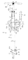
図1は本実施例の平面図、図2は本実施例の正面図、図3は図2のA−A断面図である。また、図4はブラケット組の説明図であり、(a)は平面図、(b)は正面図、(c)は側面図である。
【0019】
本実施例のステアリング支持機構1は、本発明のステアリングホイールの衝撃吸収構造を備えたものであり、ボディ取付部材2、コラム支持体3、ステアリングコラム4、ブラケット5、チルトレバー6、ステアリングシャフト7、ステアリングホイール8等から構成されている。
【0020】
ボディ取付部材2は、基部21とこの基部21の両端に設けられた一対の軸支部25,25とからなる。基部21には、略中央にステアリングシャフト7を貫通させる孔22が設けられ、この孔22の回りには複数のボルト挿通孔23が設けられている。ボディ取付部材2は、このボルト挿通孔23に挿通したボルト(図示せず)によりボディ側(図示せず)に固定される。
【0021】
コラム支持体3は、略中央にステアリングシャフトを貫通させる孔32が設けられ、ボディ取付部材2の一対の軸支部25,25にてリベット軸31,31により回動可能に取り付けられている。従って、コラム支持体3は、上下方向に回動自在に支持されている。
【0022】
ステアリングコラム4のうち下コラム41は、基端41a側がコラム支持体3に溶接され、先端41b側が後述の第1ブラケット51の貫通孔51cの周囲に溶接されている。
ブラケット5は、第1ブラケット51、第2ブラケット52、第3ブラケット53から構成される。
【0023】
第1ブラケット51は、図3及び図4に示すように、“「”形に形成された一対の板状部51a,51aと両板状部51a,51aの上面側を連結する連結部51bとがプレス加工により一体成形されたものである。この板状部51a,51aには、半径内方向に突出する複数の凸部51dが設けられた貫通孔51c,51cが穿設されている。
【0024】
第2ブラケット52は、図3及び図4に示すように、底面をなす基部52aと側面をなす一対の軸支部52b,52bとがプレス加工により一体成形されたものである。この第2ブラケット52は、第1ブラケット51の下側を覆うように、第1ブラケット51に溶接されている。一対の軸支部52b,52bには、チルト軸61を貫通するための孔52c,52cが穿設されている。尚、第1ブラケット51と第2ブラケットと52の組合せを、便宜上、ブラケット組55と称する。
【0025】
第3ブラケット53は、図3に示すように、底面部53aと、この底面部53aの両端から上方に延び出した一対の垂片部53b,53bと、この一対の垂片部53b,53bから水平方向に延び出した一対のボディ取付部53c,53cとから構成される。第3ブラケット53は、底面部53aと一対の垂片部53b,53bにより、第2ブラケットの下側を取り囲むように形成されている。また、一対の垂片部53b,53bには上下方向に延びる長孔53d,53dが相対向する位置に設けられている。この長孔53d,53dにはチルト軸61が遊嵌されている。更に、一対のボディ取付部53c,53cには取付孔53e,53eが設けられ、第3ブラケット53は、この取付孔53e,53eにボルト(図示せず)を挿通し、ボディ側(図示せず)に取り付けられる。
【0026】
チルトレバー6は、チルト軸61の一端に取り付けられ、チルト軸61を中心として、締結位置及び締結解除位置の間で回転可能に支持されている。このチルトレバー6が締結位置にあるとき、ブラケット組55は第3ブラケット53に固定され、締結解除位置にあるとき、ブラケット組55は第3ブラケット53に対して上下方向に移動可能(即ち、チルト軸61の両端が第3ブラケット53に設けた長孔53d,53dを摺動可能)となる。
【0027】
ステアリングコラム4のうちの上コラム42は、基端42a側が第1ブラケット51の貫通孔51c,51cに圧入・固定され、貫通孔51c,51cに設けた複数の凸部51dに圧接されている。尚、上コラム42と複数の凸部51dとの静止摩擦力が運転者を保護すべき衝撃(所定値)と一致するように、凸部51dの個数及び厚み(軸方向の厚み)が設定されている。一方、上コラム42の先端42a側の切削加工を施した内周面には、ステアリングシャフト7を支持するベアリング43(図2参照)が配置され、かしめにより固定されている。
【0028】
ステアリングシャフト7は、上コラム42及び下コラム41の内部を貫通し、更にコラム支持体3の孔32、ボディ取付部材2の孔22を貫通している。このステアリングシャフト7の先端7b側には、周方向に沿って設けられた2つの溝にスナップリング71(図2参照)がそれぞれ嵌合されている。両スナップリング71,71間には前記ベアリング43が介在されており、これにより、ステアリングシャフト7は上コラム42に対して軸方向に移動不能に支持されている。また、ステアリングシャフト7の先端7bには、ステアリングホイール8を取り付け可能なステアリングホイール取付部72が設けられている。
【0029】
次に、本実施例のステアリング支持機構1の動作について説明する。
最初に、チルトレバー6の操作について概説する。ステアリングホイール8の上下位置を変更する場合には、まず、運転者は、チルトレバー6を締結解除位置に移動する。すると、ステアリングシャフト7は、リベット軸31,31を中心として、第3ブラケット53に設けた長孔53d,53dの範囲内で上下方向に回動する。このため、運転者はステアリングホイール8の上下位置を所望の位置に配置し、この状態でチルトレバー6を締結位置に移動すれば、ステアリングホイール8はその位置で固定される。
【0030】
続いて、本発明の特徴であるステアリングホイール8に衝撃が加えられた場合の衝撃吸収について説明する。予め設定された所定値(複数の凸部51dと上コラム42との静止摩擦)以上の衝撃がステアリングコラム4の軸方向に沿ってステアリングホイール8に加えられると、第1ブラケット51の貫通孔51c,51cに設けた複数の凸部51dに対して上コラム42が軸方向に摺動する。このとき、上コラム42と複数の凸部51dとの間に生じる動摩擦により、衝撃が吸収され、運転者が保護される。
【0031】
このように、本実施例では、上コラム42とブラケット5により衝撃を吸収することができるため、部品点数が少なく、組付作業が簡素化され、コスト低減を図ることができるという効果が得られる。
また、上コラム42と複数の凸部51dとの間に生じる動摩擦により衝撃を吸収する構造のため、一度衝撃を吸収した後であってもこれらが破壊又は変形されるおそれは少ない。従って、一度衝撃を吸収した後であっても、上コラム42と複数の凸部51dが破壊又は変形されない限り再使用が可能であり、部品交換に必要となるコストがかからないという効果が得られる。
【0032】
更に、複数の凸部51dを備えた貫通孔51c,51cをプレス加工により設けることができるため、安定した精度を得ることができる。このため、上コラム42と複数の凸部51dとの静止摩擦を容易に(具体的には、凸部51dの数を変えたり、凸部51dの軸方向の厚みを変えたりすることにより)所望の値に調節することができる。従って、量産した場合に、各製品の衝撃吸収能を均質化することが容易であるという効果が得られる。
【0033】
尚、本発明は、上記実施例に何ら限定されることなく、本発明の技術的範囲に属する限り、種々の態様で実施できることはいうまでもない。
例えば、上記実施例では第1ブラケット51に貫通孔51c,51cを設ける構成としたが、この第1ブラケット51に代えて、略半円の円弧状の凹部を有する部材を上下から圧接する構成等を採用してもよく、この場合にも上記実施例と同様の効果が得られる。
【0034】
また、上記実施例では貫通孔51c,51cに圧接部として複数の凸部51dを設けたが、かかる凸部51dを設けることなく、貫通孔51c,51cの内周面を圧接部としてもよい。この場合、静止摩擦の大きさの調節は、貫通孔51c,51cの軸方向の厚み等によって決定することができる。
【0035】
更に、上記実施例のブラケット5を、図5に示すブラケット105の代わりに採用してもよい。これによれば、図5の従来例では一度衝撃を吸収すると樹脂部153が破壊されるためこれを交換する必要があったが、上記実施例のブラケット5を用いれば、一度衝撃を吸収しても破壊又は変形されるおそれが少ないため、破壊又は変形を受けない限り、再使用が可能となる。
【図面の簡単な説明】
【図1】本実施例の平面図である。
【図2】本実施例の正面図である。
【図3】図2のA−A断面図である。
【図4】ブラケット組の説明図であり、(a)は平面図、(b)は正面図、(c)は側面図である。
【図5】従来例の説明図である。
【図6】他の従来例の説明図である。
【符号の説明】
1・・・ステアリング支持機構、 4・・・ステアリングコラム、
5・・・ブラケット、 7・・・ステアリングシャフト、
8・・・ステアリングホイール、 41・・・下コラム、
42・・・上コラム、 51・・・第1ブラケット、
51c・・・貫通孔、 51d・・・凸部、
52・・・第2ブラケット、 53・・・第3ブラケット、
55・・・ブラケット組、[0001]
[Industrial applications]
The present invention relates to a shock absorbing structure for a steering wheel including a steering column rotatably supporting a steering shaft to which a steering wheel is attached, and a bracket for fixing the steering column to a body.
[0002]
[Prior art]
As a conventional shock absorbing structure for a steering wheel, for example, the structure shown in FIG. 5 is known. That is, of the
[0003]
According to such a shock absorbing structure, when a shock equal to or more than a predetermined value is applied to the
[0004]
However, in the shock absorbing structure of FIG. 5, since it is necessary to provide the
[0005]
On the other hand, as another conventional example, for example, a shock absorbing structure described in JP-A-6-56041 is known. As shown in FIG. 6, the shock absorbing structure includes a
[0006]
In this structure, when a vehicle collides and a shock equal to or more than a predetermined value is applied to a steering wheel (not shown), the
[0007]
According to such a shock absorbing structure, since the shock absorbing ability is high, a structure in which a
[0008]
[Problems to be solved by the invention]
However, in the shock absorbing structure of FIG. 6, the energy absorber 206 is required as a separate component in addition to the
[0009]
In addition, at the time of shock absorption, the
[0010]
Furthermore, originally, in the shock absorbing structure, it is necessary to securely absorb the shock when a shock equal to or more than a predetermined value is applied, and to fix the steering column to the body when the shock is less than the predetermined value. It is said. In this regard, in the shock absorbing structure of FIG. 6, the predetermined value is set according to the degree of swelling of the
[0011]
The present invention has been made in view of the above problems, and an object of the present invention is to provide a shock absorbing structure for a steering wheel that has a small number of parts and reduces costs.
Another object of the present invention is to provide a shock absorbing structure for a steering wheel which can easily homogenize the shock absorbing capacity of each product when mass-produced, in addition to the above objects. .
[0012]
[Means for Solving the Problems]
In order to solve the above-mentioned problem, the shock absorbing structure for a steering wheel according to the first aspect includes a steering column rotatably supporting a steering shaft to which a steering wheel is attached, and a bracket for fixing the steering column to a body side. The shock absorbing structure of a steering wheel configured, wherein the bracket is provided on a pair of plate-shaped portions provided at a predetermined distance in the axial direction of the steering column, provided on the plate-shaped portion, The steering column includes a through hole for penetrating the steering column, and a plurality of protrusions protruding inward of the through hole and pressed against the outer peripheral surface of the steering column. The steering column extends through the through hole in the axial direction. This allows sliding.
[0014]
[Action and effect of the invention]
In the shock absorbing structure for a steering wheel of the present invention having the above-described structure, when an impact less than a predetermined value (ie, static friction between the outer peripheral surface of the steering column and the press-contact portion of the bracket) is applied to the steering wheel, the steering column Does not slide on the press-contact portion of the bracket. Therefore, the steering column remains fixed to the body via the bracket. On the other hand, when an impact equal to or more than a predetermined value is applied to the steering wheel, the steering column slides on the press-contact portion of the bracket. At this time, the impact is absorbed by the dynamic friction generated between the steering column and the pressure contact portion, and the driver is protected.
[0015]
The shock absorbing structure for a steering wheel according to the present invention is composed of a steering column and a bracket, and does not require other parts. Therefore, the number of parts is small, the assembling becomes easy, and the effects of reducing costs are obtained. Also, since the shock is absorbed by the dynamic friction generated between the steering column and the pressure contact portion of the bracket, the pressure contact portion of the steering column and the bracket is less likely to be broken or deformed even after the shock is absorbed. Even after the shock is absorbed, the steering column and the bracket can be reused as long as the pressure contact portion is not broken or deformed, and the effect of eliminating the cost required for component replacement is obtained.
[0016]
Further, as described in
[0017]
Further, as described in
[0018]
【Example】
Preferred embodiments of the present invention will be described below with reference to the drawings.
FIG. 1 is a plan view of the present embodiment, FIG. 2 is a front view of the present embodiment, and FIG. 3 is a sectional view taken along line AA of FIG. 4A and 4B are explanatory views of the bracket set, wherein FIG. 4A is a plan view, FIG. 4B is a front view, and FIG. 4C is a side view.
[0019]
The
[0020]
The
[0021]
The
[0022]
The
The
[0023]
As shown in FIGS. 3 and 4, the
[0024]
As shown in FIGS. 3 and 4, the
[0025]
As shown in FIG. 3, the
[0026]
The
[0027]
The
[0028]
The steering
[0029]
Next, the operation of the
First, the operation of the
[0030]
Next, a description will be given of shock absorption when a shock is applied to the
[0031]
As described above, in this embodiment, since the impact can be absorbed by the
In addition, since the structure absorbs the impact by the dynamic friction generated between the
[0032]
Further, since the through
[0033]
It is needless to say that the present invention is not limited to the above-described embodiments, and can be implemented in various modes as long as they belong to the technical scope of the present invention.
For example, in the above embodiment, the through
[0034]
Further, in the above embodiment, a plurality of
[0035]
Further, the
[Brief description of the drawings]
FIG. 1 is a plan view of the present embodiment.
FIG. 2 is a front view of the embodiment.
FIG. 3 is a sectional view taken along line AA of FIG. 2;
4A and 4B are explanatory views of a bracket set, wherein FIG. 4A is a plan view, FIG. 4B is a front view, and FIG. 4C is a side view.
FIG. 5 is an explanatory diagram of a conventional example.
FIG. 6 is an explanatory diagram of another conventional example.
[Explanation of symbols]
1 ... steering
5 ... bracket, 7 ... steering shaft,
8 ... steering wheel, 41 ... lower column,
42 ... upper column, 51 ... first bracket,
51c ... through-hole, 51d ... convex part,
52 ... second bracket, 53 ... third bracket,
55 ... bracket set,
Claims (1)
前記ブラケットは、前記ステアリングコラムの軸方向で予め定めた距離を隔てて設けられた一対の板状部と、
該板状部に設けられ、前記ステアリングコラムを貫通させるための貫通穴と、
該貫通穴の内方向に突出し、前記ステアリングコラムの外周面に圧接される複数の凸部とから構成され、
前記ステアリングコラムが前記貫通穴を軸方向に摺動することを許容するステアリングホイールの衝撃吸収構造。A shock absorbing structure for a steering wheel, comprising a steering column rotatably supporting a steering shaft to which a steering wheel is attached, and a bracket for fixing the steering column to a body side,
The bracket is a pair of plate-shaped portions provided at a predetermined distance in the axial direction of the steering column ,
A through hole provided in the plate-shaped portion, for penetrating the steering column;
A plurality of projections protruding inward of the through hole and being pressed against the outer peripheral surface of the steering column;
An impact absorbing structure for a steering wheel that allows the steering column to slide in the through hole in the axial direction .
Priority Applications (1)
| Application Number | Priority Date | Filing Date | Title |
|---|---|---|---|
| JP00427195A JP3567006B2 (en) | 1995-01-13 | 1995-01-13 | Impact absorbing structure of steering wheel |
Applications Claiming Priority (1)
| Application Number | Priority Date | Filing Date | Title |
|---|---|---|---|
| JP00427195A JP3567006B2 (en) | 1995-01-13 | 1995-01-13 | Impact absorbing structure of steering wheel |
Publications (2)
| Publication Number | Publication Date |
|---|---|
| JPH08188162A JPH08188162A (en) | 1996-07-23 |
| JP3567006B2 true JP3567006B2 (en) | 2004-09-15 |
Family
ID=11579887
Family Applications (1)
| Application Number | Title | Priority Date | Filing Date |
|---|---|---|---|
| JP00427195A Expired - Fee Related JP3567006B2 (en) | 1995-01-13 | 1995-01-13 | Impact absorbing structure of steering wheel |
Country Status (1)
| Country | Link |
|---|---|
| JP (1) | JP3567006B2 (en) |
Families Citing this family (1)
| Publication number | Priority date | Publication date | Assignee | Title |
|---|---|---|---|---|
| JP3738200B2 (en) * | 2001-06-27 | 2006-01-25 | 光洋精工株式会社 | Shock absorbing steering device |
-
1995
- 1995-01-13 JP JP00427195A patent/JP3567006B2/en not_active Expired - Fee Related
Also Published As
| Publication number | Publication date |
|---|---|
| JPH08188162A (en) | 1996-07-23 |
Similar Documents
| Publication | Publication Date | Title |
|---|---|---|
| US8408089B2 (en) | Energy absorbing steering column | |
| JP4868213B2 (en) | Energy absorbing steering column | |
| JP4840128B2 (en) | A car equipped with a knee bolster and a knee bolster as well as a passenger limb protection method | |
| JP6309410B2 (en) | Engine support structure for saddle-ride type vehicles | |
| WO2013051441A1 (en) | Steering column device | |
| JP5054444B2 (en) | Rear impact shock absorbing unit, reclining device, and vehicle seat frame structure | |
| JP2010006323A (en) | Impact absorbing type steering device | |
| JP3567006B2 (en) | Impact absorbing structure of steering wheel | |
| JP2010188901A (en) | Energy absorption steering column | |
| JP2009051353A (en) | Position adjustment type steering device | |
| JP3748026B2 (en) | Steering device | |
| JP3181488B2 (en) | Shock absorbing steering device | |
| US3740068A (en) | Steering column support assembly | |
| JP3698820B2 (en) | Shock absorbing steering column jacket and its assembly method | |
| JP2000219139A (en) | Steering device and shock energy absorber used for it | |
| JP4335578B2 (en) | Vehicle-adjustable steering column device | |
| JP4622638B2 (en) | Rack and pinion type steering gear | |
| JP3264416B2 (en) | Mounting bracket for hydraulic shock absorber | |
| JP5001519B2 (en) | Steering device | |
| JP7659150B2 (en) | Mounting fixture | |
| JP2021071123A (en) | Resin panel attachment structure | |
| JP4257483B2 (en) | Shock absorbing steering device and manufacturing method thereof | |
| JP2000006820A (en) | Shock absorbing steering column device | |
| KR20130131746A (en) | Steering column of vehicle | |
| JP2005047319A (en) | Steering device |
Legal Events
| Date | Code | Title | Description |
|---|---|---|---|
| A977 | Report on retrieval |
Free format text: JAPANESE INTERMEDIATE CODE: A971007 Effective date: 20040210 |
|
| A131 | Notification of reasons for refusal |
Free format text: JAPANESE INTERMEDIATE CODE: A131 Effective date: 20040217 |
|
| A521 | Written amendment |
Free format text: JAPANESE INTERMEDIATE CODE: A523 Effective date: 20040402 |
|
| TRDD | Decision of grant or rejection written | ||
| A01 | Written decision to grant a patent or to grant a registration (utility model) |
Free format text: JAPANESE INTERMEDIATE CODE: A01 Effective date: 20040518 |
|
| A61 | First payment of annual fees (during grant procedure) |
Free format text: JAPANESE INTERMEDIATE CODE: A61 Effective date: 20040614 |
|
| R150 | Certificate of patent or registration of utility model |
Free format text: JAPANESE INTERMEDIATE CODE: R150 |
|
| LAPS | Cancellation because of no payment of annual fees |