JP3565741B2 - Head support arm, method of manufacturing the same, and data recording device - Google Patents
Head support arm, method of manufacturing the same, and data recording device Download PDFInfo
- Publication number
- JP3565741B2 JP3565741B2 JP15916899A JP15916899A JP3565741B2 JP 3565741 B2 JP3565741 B2 JP 3565741B2 JP 15916899 A JP15916899 A JP 15916899A JP 15916899 A JP15916899 A JP 15916899A JP 3565741 B2 JP3565741 B2 JP 3565741B2
- Authority
- JP
- Japan
- Prior art keywords
- flexure
- slider
- support arm
- load beam
- head support
- Prior art date
- Legal status (The legal status is an assumption and is not a legal conclusion. Google has not performed a legal analysis and makes no representation as to the accuracy of the status listed.)
- Expired - Fee Related
Links
- 238000004519 manufacturing process Methods 0.000 title description 11
- 229920001187 thermosetting polymer Polymers 0.000 claims description 16
- 239000000853 adhesive Substances 0.000 claims description 13
- 230000001070 adhesive effect Effects 0.000 claims description 13
- 239000011347 resin Substances 0.000 claims description 13
- 229920005989 resin Polymers 0.000 claims description 13
- 238000010438 heat treatment Methods 0.000 claims description 8
- 230000000694 effects Effects 0.000 description 3
- 238000005452 bending Methods 0.000 description 2
- 238000010586 diagram Methods 0.000 description 2
- 230000006870 function Effects 0.000 description 2
- 230000001678 irradiating effect Effects 0.000 description 2
- 238000000034 method Methods 0.000 description 2
- 230000002159 abnormal effect Effects 0.000 description 1
- 239000000919 ceramic Substances 0.000 description 1
- 239000003795 chemical substances by application Substances 0.000 description 1
- 230000005611 electricity Effects 0.000 description 1
- 229910001220 stainless steel Inorganic materials 0.000 description 1
- 239000010935 stainless steel Substances 0.000 description 1
- 230000003068 static effect Effects 0.000 description 1
- 239000010409 thin film Substances 0.000 description 1
Images


Classifications
-
- G—PHYSICS
- G11—INFORMATION STORAGE
- G11B—INFORMATION STORAGE BASED ON RELATIVE MOVEMENT BETWEEN RECORD CARRIER AND TRANSDUCER
- G11B5/00—Recording by magnetisation or demagnetisation of a record carrier; Reproducing by magnetic means; Record carriers therefor
- G11B5/48—Disposition or mounting of heads or head supports relative to record carriers ; arrangements of heads, e.g. for scanning the record carrier to increase the relative speed
- G11B5/4806—Disposition or mounting of heads or head supports relative to record carriers ; arrangements of heads, e.g. for scanning the record carrier to increase the relative speed specially adapted for disk drive assemblies, e.g. assembly prior to operation, hard or flexible disk drives
- G11B5/4853—Constructional details of the electrical connection between head and arm
-
- G—PHYSICS
- G11—INFORMATION STORAGE
- G11B—INFORMATION STORAGE BASED ON RELATIVE MOVEMENT BETWEEN RECORD CARRIER AND TRANSDUCER
- G11B21/00—Head arrangements not specific to the method of recording or reproducing
- G11B21/16—Supporting the heads; Supporting the sockets for plug-in heads
- G11B21/24—Head support adjustments
-
- G—PHYSICS
- G11—INFORMATION STORAGE
- G11B—INFORMATION STORAGE BASED ON RELATIVE MOVEMENT BETWEEN RECORD CARRIER AND TRANSDUCER
- G11B5/00—Recording by magnetisation or demagnetisation of a record carrier; Reproducing by magnetic means; Record carriers therefor
- G11B5/48—Disposition or mounting of heads or head supports relative to record carriers ; arrangements of heads, e.g. for scanning the record carrier to increase the relative speed
- G11B5/4806—Disposition or mounting of heads or head supports relative to record carriers ; arrangements of heads, e.g. for scanning the record carrier to increase the relative speed specially adapted for disk drive assemblies, e.g. assembly prior to operation, hard or flexible disk drives
- G11B5/4826—Mounting, aligning or attachment of the transducer head relative to the arm assembly, e.g. slider holding members, gimbals, adhesive
Description
【0001】
【発明の属する技術分野】
本発明は、ロード・ビームと、ロード・ビームに結合された部分及びボンディング部分を含むフレクシャと、接着剤によりボンディング部分を接着された、一端にヘッドを有するスライダとを備え、ロード・ビームが、フレクシャとスライダのジンバル動作を生じさせるためのディンプルを有する構造のヘッド支持アーム、その製造方法及びデータ記録装置に関するものである。
【0002】
【従来の技術】
従来から、ロード・ビームと、ロード・ビームに結合された部分及びボンディング部分を含むフレクシャと、接着剤によりボンディング部分を接着された、一端にヘッドを有するスライダとを備え、ロード・ビームが、フレクシャとスライダのジンバル動作を生じさせるためのディンプルを有する構造のヘッド支持アームは種々の構成のものが知られており、ハード・ディスク・装置等において読み取り/書き込み用のヘッドを支持するために利用されている。近年、記録密度の向上に伴い、ヘッドとしてMRヘッドやGMRヘッドなどのよりセンシティブで静電気や熱に弱いものが使用されてきている。一方、スライダの浮上量も限界近くまで下げてきており、熱変化による、ステンレス製のフレクシャとセラミック製のスライダ間のバイメタル効果による変形も無視出来なくなってきている。
【0003】
こうした背景から、フレクシャとスライダとを接着固定するために、硬化後の熱変化の小さい熱硬化性樹脂等の接着剤を使用することが多くなっている。熱硬化性樹脂を使用してフレクシャとスライダとを接着固定する場合は、まず、生産工程の効率を上げるため、熱硬化性樹脂を介してセットしたフレクシャとスライダのうちフレクシャにレーザ・ビームを短時間照射して仮止め(レーザ・タック)を行い、その後、フレクシャとスライダとを仮止めしたヘッド支持アーム全体を加熱炉内で加熱し、熱硬化性樹脂全体を加熱硬化させている。
【0004】
【発明が解決しようとする課題】
このようなレーザ・タックを伴うフレクシャとスライダの接着は、ヘッド支持アームの先端にロード/アンロード用のマージ・リップが必要のないコンタクト・スタート・ストップ(CSS)方式のヘッド支持アームでは簡単に実現できるが、近年多用されるロード/アンロード用のマージ・リップが必要なヘッド支持アームでは、そのままではロード・ビームによりフレクシャのほとんどが覆われているため、レーザ・タックができない問題があった。
【0005】
この問題を解消するため、本出願人は特願平10−370272号において、フレクシャのスライダを接着するボンディング部分を露出する露出開口をロード・ビームに設け、この露出開口を利用してレーザ・ビームをフレクシャのボンディング部分に照射し、ロード/アンロード用のマージ・リップが存在するヘッド支持アームでもレーザ・タックを実現可能とする技術を開示している。しかし、特願平10−370272号において開示された技術は、近年用いられるようになった、データ記録媒体からヘッドをアンロードする時などにヘッドすなわちスライダがロード・ビームから離れすぎないよう作用するリミッタのための開口をもロード・ビームに必要とするヘッド支持アームを対象にしていなかった。
【0006】
本発明の目的は上述した課題を解消して、ロード・アンロード用のマージ・リップ及びリミッタを有するヘッド支持アームにおいてレーザ・タックを行うことのできるヘッド支持アーム、その製造方法及びデータ記録装置を提供しようとするものである。
【0007】
【課題を解決するための手段】
本発明のヘッド支持アームは、ロード・ビームと、ロード・ビームに結合された部分及びボンディング部分を含むフレクシャと、接着剤によりボンディング部分を接着された、一端にヘッドを有するスライダとを備え、ロード・ビームが、フレクシャとスライダのジンバル動作を生じさせるためのディンプルを有する構造のヘッド支持アームを対象とする。このヘッド支持アームにおいて、(1)スライダのヘッドを設けた一端に対して反対側の他端に接着されたフレクシャのボンディング部分を露出させる露出開口を、ロード・ビームに設けるとともに、(2)フレクシャと一体に設けられたリミッタを露出開口のフレクシャの存在する面に対し反対側の面まで延在させ、リミッタをロード・ビームに係合させた。
【0008】
本発明ヘッド支持アームでは、ヘッドを有するスライダ、フレクシャ、ロード・ビーム等からなるヘッド支持アームにおけるヘッド・ジンバル・アセンブリ(HGA)において、フレクシャとスライダとを接着するための熱硬化性樹脂からなる接着剤の仮止めに用いる露出開口を、ロード/アンロード用のリミッタの開口としても利用することで共通化し、露出開口にリミッタを係合させている。そのため、ロード/アンロード用のマージ・リップ及びリミッタの機能を持ったまま、レーザ・タックのためのレーザ照射が可能となるとともに、そのレーザ照射位置がGMRヘッド等の熱に弱いエレメントより離れたところにあるため、その熱上昇も抑えることができる。その結果、ヘッド支持アームをシンプルでコンパクトに構成することが可能となる。また、本発明の露出開口の構成であれば、強度的に弱くなるロード・ビーム上の部位は存在しない。
【0009】
本発明のヘッド支持アームにおける好適例として、露出開口がほぼ四角形でありその一辺の大きさが、フレクシャのボンディング部分の幅方向の大きさより大きくなるよう構成すること、リミッタが、露出開口のディンプルに対し遠い側の一辺に係合するよう構成することが挙げられる。いずれの場合も、レーザ照射用の開口とリミッタ用の開口とを供用する露出開口を好適に実現することができる。
【0010】
また、本発明のヘッド支持アームの製造方法は、上述した構成のヘッド支持アームの製造方法を対象とする。まず、フレクシャのリミッタをロード・ビームの露出開口に係合させた状態で、ロード・ビームに対しフレクシャのボンディング部分に熱硬化性樹脂を介してスライダを配置する。次に、露出開口を介してフレクシャの露出しているボンディング部分の一部にレーザ・ビームを照射し、レーザ・ビームの熱で熱硬化性接着剤を硬化させてフレクシャとスライダとを仮固定する。その後、フレクシャとスライダとを仮固定したヘッド支持アームを加熱炉内で加熱することで熱硬化性樹脂をさらに加硫して、フレクシャとスライダとを接着固定する。上述した製造方法によれば、ロード/アンロード用のマージ・リップ及びリミッタを備えるヘッド支持アームを、歩留まり良く製造することができる。
【0011】
さらに、本発明のデータ記録装置は、データを記録するデータ記録媒体と、データ記録媒体に対して相対的に移動する上述した構成のヘッド支持アームとから構成される。上述した構成のデータ記録装置は、ロード/アンロード用のマージ・リップ及びリミッタを備えるヘッド支持アームを好適に利用してデータ記録装置を構成することができる。
【0012】
【発明の実施の形態】
図1は、本発明に従うヘッド支持アーム31を含むハード・ディスク・ドライブ(HDD)装置の回路ブロック図である。磁気データ記録用ハード・ディスク10を回転させるスピンドル・モータ11及びボイス・コイル・モータ(VCM)は、VCM/スピンドル・ドライバ12により制御される。読み取り/書き込み回路14はハード・ディスク制御回路15に接続され、そしてこの回路15はVCM/スピンドル・ドライバ12に接続されている。データ及び制御データを記憶するためのメモリ16が回路15及び主制御回路すなわちMPU13に接続され、MPU13はVCM/スピンドル・ドライバ12、ハード・ディスク制御回路15及びメモリ16を制御する。読み取り/書き込みヘッドはスライダ(図示せず)に装着される。スライダはヘッド支持アーム31の先端部に装着される。ヘッド支持アーム31の後部はハード・ディスク・ドライブ装置のフレームの枢着されている。
【0013】
また、内側クラッシュ停止材17がフレームに装着されており、ヘッド支持アーム31に係合して読み取り/書き込みヘッドを、最も内側のデータ記録トラック上に位置決めする。ランプ素子18がHDD装置のフレームに装着される。このHDD装置はロード/アンロード方式で動作され、待機状態ではヘッド支持アーム31の先端のマージ・リップ21がランプ素子18上に乗り、そして読み取り/書き込み動作が開始されると、ヘッド支持アーム31はハード・ディスク10に中心に向かって移動され、これにより先端のマージ・リップ21はランプ素子18からはずれてそしてスライダ及び読み取り/書き込みヘッドはディスク上で飛行する。なお、上述したHDD装置の特徴は、後述するヘッド支持アーム31の構造であり、その他の構成は従来のHDD装置と同じである。
【0014】
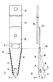
図2は本発明のヘッド支持アーム31の一実施例を示す図であり、図2(a)はその平面図を、図2(b)はその側面図をそれぞれ示している。図2(a)、(b)に示す実施例において、ヘッド支持アーム31は、枢着点33でHDD装置のフレームに装着されるアクチュエータ・アーム32、ロード・ビーム34、ロード・ビーム34をアクチュエータ・アーム32に接続するマウント・プレート35、結合点45(図3)でロード・ビーム34に取り付けられたフレクシャ36、フレクシャ36のボンディング部分36Aに取り付けられたスライダ37とから構成されている。ここで、スライダ37、フレクシャ36、ロード・ビーム34及びマウント・プレート35は、ヘッド・ジンバル・アセンブリ(HGA)と呼ばれる。
【0015】
図3は本発明のヘッド支持アーム31におけるロード・ビーム34、フレクシャ36及びスライダ37の一実施例を説明するための図であり、図3(a)はその平面図を、図3(b)はその側面図をそれぞれ示している。図3(a)、(b)に示す実施例において、MRヘッドやGMRヘッドのような読み取り/書き込みヘッド43はスライダ37の先端に取り付けられている薄膜44上に装着されている。ロード・ビーム34上の突出部すなわちディンプル42は、スライダ37及び読み取り/書き込みヘッド43を支持するフレクシャ36のボンディング部分36Aに接触して、スライダ37及びヘッド43のジンバル動作を実現する。また、開口部51がロード・ビーム34に形成されており、ロード・ビーム34の屈曲部52を規定する。ロード・ビーム34は、図2(b)に示すように、屈曲部52で屈曲することにより2つの位置の間で移動される。さらに、開口53がスライダ37の先端のヘッド43に対応する位置でロード・ビーム34に形成されており、例えばヘッド43からの接続ワイヤ等をロード・ビーム54のヘッド43とは反対側の面に導くために利用されている。
【0016】
本発明のヘッド支持アーム31における最大の特徴は、ロード・ビーム54に、スライダ37のヘッド43を設けた一端に対して反対側の他端に接着されたフレクシャ36のボンディング部分36Aを露出させる露出開口61を形成した点、および、フレクシャ36と一体に設けられた2つのリミッタ62を露出開口61のフレクシャ36の存在する面に対し反対側の面まで延在させ、リミッタ62の先端62Aをロード・ビーム34に係合させた点である。上述した構成をとることで、この露出開口61を利用して、図3(a)に示す上面からレーザ・ビームをボンディング部分36AのA部に照射してレーザ・タックを行えるよう構成することができる。また、専用の開口を設けることなく、レーザ・タック用に設けた露出開口61を利用して、例えばアンロード時のスライダ37の異常な動作を防止するリミッタ62をロード・ビーム34に対して形成することができる。
【0017】
なお、上述した実施例では、露出開口61の形状がほぼ四角形であり、その一辺の大きさが、フレクシャ36のボンディング部分36Aの幅方向の大きさより大きくなるよう形成している。これは、2つのリミッタ62がフレクシャ36のボンディング部分36Aの幅方向の両端に設けられており、これらのリミッタ62を露出開口61を介してロード・ビーム34に対してセットするために必要なためである。もちろん、リミッタ62の形状に応じて、すなわち、リミッタ62が例えばボンディング部分36Aの幅方向の中央に1カ所だけ設けられているような場合は、露出開口61の一辺をそのリミッタ62の幅より少なくとも大きくなるよう形成すれば良い。また、露出開口61の形状も四角形に限定されるものではない。さらに、上述した実施例では、リミッタ62の先端62Aが、露出開口61のディンプル42に対して遠い側の一辺に係合するよう構成している。これは、この位置でリミッタ62の先端62Aをロード・ビーム34に係合させることで、リミッタ62の効果を最大限発揮できるためである。しかし、他の位置例えば露出開口61の側面でリミッタ62の先端62Aをロード・ビーム34に係合するよう構成しても、上述した例よりは若干劣るが十分リミッタ62として利用できることは言うまでもない。
【0018】
上述した構成のヘッド支持アーム31を製造するには、まず、フレクシャ36のリミッタ62をロード・ビーム34の露出開口に係合させた状態で、ロード・ビーム34に対しフレクシャ36のボンディング部分36Aに熱硬化性樹脂を介してスライダ37を配置する。次に、露出開口62を介してフレクシャ36の露出しているボンディング部分36Aの一部にレーザ・ビームを照射し、レーザ・ビームの熱で熱硬化性接着剤を硬化させてフレクシャ36とスライダ37とを仮固定する。その後、フレクシャ36とスライダ37とを仮固定したヘッド支持アーム31を加熱炉内で加熱することで熱硬化性樹脂をさらに加硫して、フレクシャ36とスライダ37とを接着固定する。上述したヘッド支持アーム31の製造方法において重要な点は、リミッタ62を係合するのに利用した露出開口61を利用してレーザ・タックを行う点であり、その他の各工程は、従来と同様の工程で製造することができる。上述した製造方法によれば、ロード/アンロード用のマージ・リップ21及びリミッタ62を備えるヘッド支持アーム31を、歩留まり良く製造することができる。
【0019】
【発明の効果】
以上の説明から明らかなように、本発明によれば、フレクシャとスライダとを接着するための熱硬化性樹脂からなる接着剤の仮止めに用いる露出開口を、ロード/アンロード用のリミッタの開口としても利用することで共通化し、露出開口にリミッタを係合させている。そのため、ロード/アンロード用のマージ・リップ及びリミッタの機能を持ったまま、レーザ・タックのためのレーザ照射が可能となるとともに、そのレーザ照射位置がGMRヘッド等の熱に弱いエレメントより離れたところにあるため、その熱上昇も抑えることができる。その結果、ヘッド支持アームをシンプルでコンパクトに構成することが可能となる。また、本発明の露出開口の構成であれば、強度的に弱くなるロード・ビーム上の部位は存在しない。
【図面の簡単な説明】
【図1】本発明に従うヘッド支持アームを含むHDD装置の回路ブロック図である。
【図2】(a)、(b)はそれぞれ本発明のヘッド支持アームの一実施例を示す平面図及び側面図である。
【図3】(a)、(b)はそれぞれ本発明のヘッド支持アームにおけるロード・ビーム、フレクシャ及びスライダの一実施例を示す平面図及び側面図である。
【符号の説明】
10 ハード・ディスク、21 マージ・リップ、31 ヘッド支持アーム、34 ロード・ビーム、36 フレクシャ、36A ボンディング部分、37 スライダ、42 ディンプル、43 ヘッド、51、53 開口、61 露出開口、62 リミッタ、62A 先端[0001]
TECHNICAL FIELD OF THE INVENTION
The present invention comprises a load beam, a flexure including a portion coupled to the load beam and a bonding portion, and a slider having a head at one end to which the bonding portion is bonded by an adhesive, wherein the load beam includes: The present invention relates to a head support arm having a structure having dimples for causing a gimbal operation of a flexure and a slider, a method of manufacturing the same, and a data recording apparatus.
[0002]
[Prior art]
Conventionally, there is provided a load beam, a flexure including a portion connected to the load beam and a bonding portion, and a slider having a head at one end to which the bonding portion is adhered by an adhesive, wherein the load beam includes a flexure. Various types of head support arms having dimples for causing a gimbal operation of a slider and a slider are known, and are used for supporting a read / write head in a hard disk device or the like. ing. In recent years, with the improvement in recording density, more sensitive heads, such as MR heads and GMR heads, which are susceptible to static electricity and heat, have been used. On the other hand, the flying height of the slider has also been reduced to near the limit, and deformation due to the bimetal effect between the stainless steel flexure and the ceramic slider due to thermal change cannot be ignored.
[0003]
From such a background, in order to fix and fix the flexure and the slider, an adhesive such as a thermosetting resin having a small heat change after curing is often used. In the case where the flexure and the slider are bonded and fixed by using a thermosetting resin, first, in order to increase the efficiency of the production process, the laser beam is shorted to the flexure of the flexure and the slider set via the thermosetting resin. Temporary fixing (laser tack) is performed by irradiating for a time, and thereafter, the entire head support arm temporarily fixing the flexure and the slider is heated in a heating furnace, and the entire thermosetting resin is cured by heating.
[0004]
[Problems to be solved by the invention]
Bonding the flexure and slider with such a laser tack is easy with a contact start stop (CSS) type head support arm that does not require a load / unload merge lip at the end of the head support arm. Although it can be realized, the head support arm that requires a load / unload merge lip that is frequently used in recent years has a problem that laser tack cannot be performed because most of the flexure is covered by the load beam as it is. .
[0005]
In order to solve this problem, the present applicant has disclosed in Japanese Patent Application No. 10-370272, an exposure opening for exposing a bonding portion for bonding a flexure slider to a load beam, and utilizing this exposure opening, a laser beam is provided. To the bonding portion of the flexure to realize laser tack even in a head supporting arm having a load / unload merge lip. However, the technique disclosed in Japanese Patent Application No. 10-370272, which has been used in recent years, acts to prevent the head, that is, the slider, from being too far from the load beam when unloading the head from the data recording medium. The apertures for the limiters were also not intended for head support arms that required the load beam.
[0006]
SUMMARY OF THE INVENTION An object of the present invention is to provide a head support arm capable of performing laser tack in a head support arm having a merge lip and a limiter for loading and unloading, a manufacturing method thereof, and a data recording apparatus. It is what we are going to offer.
[0007]
[Means for Solving the Problems]
The head support arm of the present invention includes a load beam, a flexure including a portion coupled to the load beam and a bonding portion, and a slider having a head at one end to which the bonding portion is bonded by an adhesive. The beam is intended for a head supporting arm having a dimple for causing a gimbal operation of a flexure and a slider. In this head support arm, (1) an exposure opening for exposing a bonding portion of a flexure bonded to the other end opposite to one end where the slider head is provided is provided in the load beam, and (2) a flexure is provided. A limiter provided integrally with the load beam was extended to a surface of the exposure opening opposite to the surface where the flexure is present, and the limiter was engaged with the load beam.
[0008]
According to the head support arm of the present invention, in a head gimbal assembly (HGA) of the head support arm including a slider having a head, a flexure, a load beam and the like, an adhesive made of a thermosetting resin for bonding the flexure and the slider. The exposure opening used for temporary fixing of the agent is also used as the opening of the limiter for loading / unloading, so that the limiter is engaged with the exposure opening. Therefore, laser irradiation for laser tack can be performed while having the functions of the merge lip and limiter for load / unload, and the laser irradiation position is separated from a heat-sensitive element such as a GMR head. However, the heat rise can be suppressed. As a result, the head support arm can be configured simply and compactly. Further, according to the configuration of the exposure opening of the present invention, there is no portion on the load beam that becomes weak in strength.
[0009]
As a preferred example of the head support arm of the present invention, the exposure opening is substantially rectangular, and the size of one side thereof is configured to be larger than the widthwise size of the bonding portion of the flexure. A configuration that engages with one side on the far side is mentioned. In any case, it is possible to suitably realize an exposure opening serving as an opening for laser irradiation and an opening for a limiter.
[0010]
A method of manufacturing a head support arm according to the present invention is directed to a method of manufacturing a head support arm having the above-described configuration. First, with the limiter of the flexure engaged with the exposure opening of the load beam, the slider is arranged on the bonding portion of the flexure with respect to the load beam via a thermosetting resin. Next, a part of the exposed bonding portion of the flexure is irradiated with a laser beam through the exposure opening, and the thermosetting adhesive is cured by the heat of the laser beam to temporarily fix the flexure and the slider. . Then, the thermosetting resin is further vulcanized by heating the head support arm in which the flexure and the slider are temporarily fixed in a heating furnace, and the flexure and the slider are bonded and fixed. According to the above-described manufacturing method, it is possible to manufacture the head support arm including the load / unload merge lip and the limiter with high yield.
[0011]
Further, the data recording device of the present invention includes a data recording medium for recording data, and a head support arm having the above-described configuration which moves relatively to the data recording medium. The data recording device having the above-described configuration can be configured using a head support arm including a merge lip and a limiter for loading / unloading.
[0012]
BEST MODE FOR CARRYING OUT THE INVENTION
FIG. 1 is a circuit block diagram of a hard disk drive (HDD) device including a
[0013]
Also, an
[0014]
2A and 2B are views showing an embodiment of the
[0015]
FIG. 3 is a view for explaining an embodiment of the
[0016]
The most important feature of the
[0017]
In the above-described embodiment, the shape of the exposure opening 61 is substantially rectangular, and the size of one side thereof is larger than the size of the
[0018]
In order to manufacture the
[0019]
【The invention's effect】
As is apparent from the above description, according to the present invention, the exposure opening used for temporarily fixing the adhesive made of a thermosetting resin for bonding the flexure and the slider is changed to the opening of the load / unload limiter. The limiter is engaged with the exposed opening. Therefore, laser irradiation for laser tack can be performed while having the functions of the merge lip and limiter for load / unload, and the laser irradiation position is separated from a heat-sensitive element such as a GMR head. However, the heat rise can be suppressed. As a result, the head support arm can be configured simply and compactly. Further, according to the configuration of the exposure opening of the present invention, there is no portion on the load beam that becomes weak in strength.
[Brief description of the drawings]
FIG. 1 is a circuit block diagram of an HDD device including a head support arm according to the present invention.
FIGS. 2A and 2B are a plan view and a side view, respectively, showing one embodiment of a head support arm of the present invention.
FIGS. 3A and 3B are a plan view and a side view showing one embodiment of a load beam, a flexure, and a slider in a head support arm of the present invention, respectively.
[Explanation of symbols]
10 hard disk, 21 merge lip, 31 head support arm, 34 load beam, 36 flexure, 36A bonding portion, 37 slider, 42 dimple, 43 head, 51, 53 opening, 61 exposure opening, 62 limiter, 62A tip
Claims (5)
Priority Applications (7)
| Application Number | Priority Date | Filing Date | Title |
|---|---|---|---|
| JP15916899A JP3565741B2 (en) | 1999-06-07 | 1999-06-07 | Head support arm, method of manufacturing the same, and data recording device |
| MYPI20002293A MY125384A (en) | 1999-06-07 | 2000-05-24 | Head supporting arm, data recording apparatus, with laser beam exposing aperture and limiter |
| KR10-2000-0028239A KR100387209B1 (en) | 1999-06-07 | 2000-05-25 | Head supporting arm, method for manufacturing the same, and data recording apparatus |
| FR0006688A FR2795854B1 (en) | 1999-06-07 | 2000-05-25 | ARM HOLDER, METHOD FOR MANUFACTURING THE SAME AND DATA RECORDING APPARATUS |
| SG200002912A SG93867A1 (en) | 1999-06-07 | 2000-05-29 | Head supporting arm, method for manufacturing the same, and data recording apparatus |
| CNB001181157A CN1149570C (en) | 1999-06-07 | 2000-06-06 | Magnetic head supporting arm, its making method and data recording device |
| US09/590,659 US6556384B1 (en) | 1999-06-07 | 2000-06-07 | Head supporting arm, Data recording apparatus, with laser beam exposing aperture and limiter |
Applications Claiming Priority (1)
| Application Number | Priority Date | Filing Date | Title |
|---|---|---|---|
| JP15916899A JP3565741B2 (en) | 1999-06-07 | 1999-06-07 | Head support arm, method of manufacturing the same, and data recording device |
Publications (2)
| Publication Number | Publication Date |
|---|---|
| JP2000348454A JP2000348454A (en) | 2000-12-15 |
| JP3565741B2 true JP3565741B2 (en) | 2004-09-15 |
Family
ID=15687774
Family Applications (1)
| Application Number | Title | Priority Date | Filing Date |
|---|---|---|---|
| JP15916899A Expired - Fee Related JP3565741B2 (en) | 1999-06-07 | 1999-06-07 | Head support arm, method of manufacturing the same, and data recording device |
Country Status (7)
| Country | Link |
|---|---|
| US (1) | US6556384B1 (en) |
| JP (1) | JP3565741B2 (en) |
| KR (1) | KR100387209B1 (en) |
| CN (1) | CN1149570C (en) |
| FR (1) | FR2795854B1 (en) |
| MY (1) | MY125384A (en) |
| SG (1) | SG93867A1 (en) |
Families Citing this family (12)
| Publication number | Priority date | Publication date | Assignee | Title |
|---|---|---|---|---|
| US6965501B1 (en) | 2000-09-28 | 2005-11-15 | Hitachi Global Storage Technologies, The Netherlands B.V. | Integrated lead suspension for high density drive |
| JP4144197B2 (en) * | 2001-07-04 | 2008-09-03 | 新科實業有限公司 | Vibration suppression mechanism and head gimbal assembly with vibration suppression mechanism |
| US6801400B2 (en) * | 2002-01-24 | 2004-10-05 | Hitachi Global Storage Technologies, The Netherlands B.V. | Motion limiter for disk drive integrated gimbal suspension |
| US7130157B2 (en) * | 2002-08-14 | 2006-10-31 | Seagate Technology Llc | Head suspension having a displacement limiter |
| JP4104957B2 (en) | 2002-11-07 | 2008-06-18 | 日本発条株式会社 | Suspension component joining processing equipment |
| WO2004066279A1 (en) * | 2003-01-20 | 2004-08-05 | Sae Magnetics (H.K.) Ltd. | System and method for manufacture of hard disc drive arm and bonding of magnetic head to suspension on a drive arm. |
| US20050013053A1 (en) * | 2003-07-16 | 2005-01-20 | Momo Boljanovic | Suspension pitch limiters tandem design |
| JP4215658B2 (en) * | 2004-02-18 | 2009-01-28 | ヒタチグローバルストレージテクノロジーズネザーランドビーブイ | Suspension and data storage device |
| US7359145B2 (en) * | 2004-06-30 | 2008-04-15 | Imation Corp. | Non-tape data storage cartridge with handling feature and associated cartridge drive |
| KR100660911B1 (en) * | 2006-01-11 | 2006-12-26 | 삼성전자주식회사 | Suspension assembly of the actuator for hard disk drive |
| JP5225647B2 (en) * | 2007-10-03 | 2013-07-03 | 日本発條株式会社 | Head suspension, load beam, load beam manufacturing method, and workpiece machining method |
| JP4839293B2 (en) * | 2007-10-04 | 2011-12-21 | 日本発條株式会社 | Head suspension, load beam, and method of manufacturing load beam |
Family Cites Families (18)
| Publication number | Priority date | Publication date | Assignee | Title |
|---|---|---|---|---|
| JPH02257481A (en) * | 1988-07-21 | 1990-10-18 | Insite Peripherals Inc | Head for disk driving mechanism |
| US5333085A (en) * | 1990-11-06 | 1994-07-26 | Seagate Technology, Inc. | Read/write gimbal with limited range of motion |
| JPH0714333A (en) * | 1993-06-24 | 1995-01-17 | Hitachi Ltd | Magnetic head |
| JPH07192421A (en) * | 1993-12-28 | 1995-07-28 | Toshiba Corp | Information recording/reproducing device |
| US5838517A (en) * | 1995-12-01 | 1998-11-17 | International Business Machines Corporation | Shock protected high stack density suspension system |
| US5771136A (en) * | 1996-05-23 | 1998-06-23 | Hutchinson Technology Incorporated | Suspension assembly for mounting a head slider having a flexure with a shock limiter |
| JP2828040B2 (en) * | 1996-07-05 | 1998-11-25 | 日本電気株式会社 | Magnetic head assembly |
| US5877920A (en) * | 1996-07-10 | 1999-03-02 | Seagate Technology, Inc. | Head suspension assembly with displacement limiter |
| JP3495224B2 (en) * | 1997-06-06 | 2004-02-09 | アルプス電気株式会社 | Magnetic head device and method of manufacturing the same |
| US5862010A (en) * | 1997-07-08 | 1999-01-19 | International Business Machines Corporation | Transducer suspension system |
| JP2989568B2 (en) * | 1997-08-06 | 1999-12-13 | インターナショナル・ビジネス・マシーンズ・コーポレイション | Disk drive unit |
| JP3909934B2 (en) * | 1997-11-06 | 2007-04-25 | 日本発条株式会社 | Suspension for disk unit |
| US6055132A (en) * | 1998-06-04 | 2000-04-25 | Internatinal Business Machines Corporation | Integrated lead suspension flexure for attaching a micro-actuator with a transducer slider |
| JP3295906B2 (en) * | 1998-06-11 | 2002-06-24 | インターナショナル・ビジネス・マシーンズ・コーポレーション | Load / unload ramp and disk drive |
| JP3569144B2 (en) * | 1998-12-25 | 2004-09-22 | ヒタチグローバルストレージテクノロジーズネザーランドビーブイ | Head support arm and method of manufacturing the same |
| US6320729B1 (en) * | 1999-04-27 | 2001-11-20 | Magnecomp Corp. | Snap-in assembly of suspension limiter having both high shock and load/unload cycle capability |
| US6243235B1 (en) * | 1999-04-16 | 2001-06-05 | International Business Machines Corporation | Transducer suspension system with limiter |
| US6172853B1 (en) * | 1999-05-20 | 2001-01-09 | Hutchinson Technology Incorporated | Head suspension having a near dimple motion limiter |
-
1999
- 1999-06-07 JP JP15916899A patent/JP3565741B2/en not_active Expired - Fee Related
-
2000
- 2000-05-24 MY MYPI20002293A patent/MY125384A/en unknown
- 2000-05-25 KR KR10-2000-0028239A patent/KR100387209B1/en not_active IP Right Cessation
- 2000-05-25 FR FR0006688A patent/FR2795854B1/en not_active Expired - Fee Related
- 2000-05-29 SG SG200002912A patent/SG93867A1/en unknown
- 2000-06-06 CN CNB001181157A patent/CN1149570C/en not_active Expired - Fee Related
- 2000-06-07 US US09/590,659 patent/US6556384B1/en not_active Expired - Lifetime
Also Published As
| Publication number | Publication date |
|---|---|
| MY125384A (en) | 2006-07-31 |
| US6556384B1 (en) | 2003-04-29 |
| SG93867A1 (en) | 2003-01-21 |
| CN1276602A (en) | 2000-12-13 |
| JP2000348454A (en) | 2000-12-15 |
| CN1149570C (en) | 2004-05-12 |
| KR20010007116A (en) | 2001-01-26 |
| KR100387209B1 (en) | 2003-06-11 |
| FR2795854A1 (en) | 2001-01-05 |
| FR2795854B1 (en) | 2006-10-27 |
Similar Documents
| Publication | Publication Date | Title |
|---|---|---|
| KR100275179B1 (en) | Disc driver apparatus | |
| US6307719B1 (en) | Suspension assembly with adjustable gramload | |
| US6965501B1 (en) | Integrated lead suspension for high density drive | |
| US7474508B1 (en) | Head gimbal assembly with air bearing slider crown having reduced temperature sensitivity | |
| US8456780B1 (en) | Uncoupled piezoelectric milli-actuator assembly | |
| US7719796B2 (en) | Suspension for hard disk drive which enables easy dynamic electric testing | |
| JP3565741B2 (en) | Head support arm, method of manufacturing the same, and data recording device | |
| US20100277827A1 (en) | Correcting Errors in Position of an HDD Write-Head | |
| US7839604B1 (en) | Disk drive suspension assembly with integrated trailing edge shock protection for use with micro-actuator type head-gimbal assembly | |
| US6388842B1 (en) | Disc drive suspension bend section and method | |
| JP3569144B2 (en) | Head support arm and method of manufacturing the same | |
| JP2007066488A (en) | Data storage device, and method of controlling same | |
| JP4302162B2 (en) | Head actuator assembly and magnetic disk drive equipped with the same | |
| US7719783B2 (en) | Hard disk drive with mechanism for controlling protrusion of head | |
| JP2006134377A (en) | Magnetic recording device and loading method | |
| JP4743855B2 (en) | Data storage device and control method thereof | |
| JP2008181645A (en) | Head slider, hard disk drive, and method of controlling flying height of head slider | |
| US20060098348A1 (en) | Microactuator, head gimbal assembly and magnetic disk drive | |
| US7375917B1 (en) | Idle seek calibration method for magnetic disk drive and magnetic disk drive with an intermission calibration | |
| US8099862B2 (en) | Apparatus for detaching a head slider joined to a mounting plate of suspension | |
| US7113370B2 (en) | Slanted mounting for preload flat suspension | |
| JP4149993B2 (en) | Recording medium driving device and lamp member assembly | |
| US7474510B1 (en) | Disk drive head reset for parked head using closely spaced magnet | |
| JPH0540927A (en) | Floating type magnetic head | |
| JP3715434B2 (en) | Magnetic disk drive and assembly method thereof |
Legal Events
| Date | Code | Title | Description |
|---|---|---|---|
| TRDD | Decision of grant or rejection written | ||
| A01 | Written decision to grant a patent or to grant a registration (utility model) |
Free format text: JAPANESE INTERMEDIATE CODE: A01 Effective date: 20040601 |
|
| A61 | First payment of annual fees (during grant procedure) |
Free format text: JAPANESE INTERMEDIATE CODE: A61 Effective date: 20040608 |
|
| R150 | Certificate of patent or registration of utility model |
Free format text: JAPANESE INTERMEDIATE CODE: R150 |
|
| FPAY | Renewal fee payment (event date is renewal date of database) |
Free format text: PAYMENT UNTIL: 20080618 Year of fee payment: 4 |
|
| FPAY | Renewal fee payment (event date is renewal date of database) |
Free format text: PAYMENT UNTIL: 20080618 Year of fee payment: 4 |
|
| FPAY | Renewal fee payment (event date is renewal date of database) |
Free format text: PAYMENT UNTIL: 20090618 Year of fee payment: 5 |
|
| LAPS | Cancellation because of no payment of annual fees |