JP3565166B2 - Electrical cable connector - Google Patents
Electrical cable connector Download PDFInfo
- Publication number
- JP3565166B2 JP3565166B2 JP2000404230A JP2000404230A JP3565166B2 JP 3565166 B2 JP3565166 B2 JP 3565166B2 JP 2000404230 A JP2000404230 A JP 2000404230A JP 2000404230 A JP2000404230 A JP 2000404230A JP 3565166 B2 JP3565166 B2 JP 3565166B2
- Authority
- JP
- Japan
- Prior art keywords
- cable
- connector
- support member
- clamp
- tail
- Prior art date
- Legal status (The legal status is an assumption and is not a legal conclusion. Google has not performed a legal analysis and makes no representation as to the accuracy of the status listed.)
- Expired - Fee Related
Links
- 239000011810 insulating material Substances 0.000 claims description 6
- 230000013011 mating Effects 0.000 claims description 3
- 239000002775 capsule Substances 0.000 claims 1
- 239000004020 conductor Substances 0.000 claims 1
- 238000003466 welding Methods 0.000 description 6
- 238000000034 method Methods 0.000 description 4
- 230000008569 process Effects 0.000 description 4
- 238000005304 joining Methods 0.000 description 3
- 238000005476 soldering Methods 0.000 description 3
- 230000000712 assembly Effects 0.000 description 2
- 238000000429 assembly Methods 0.000 description 2
- 230000010354 integration Effects 0.000 description 2
- 239000000463 material Substances 0.000 description 2
- 230000009471 action Effects 0.000 description 1
- 239000000853 adhesive Substances 0.000 description 1
- 230000001070 adhesive effect Effects 0.000 description 1
- 238000010586 diagram Methods 0.000 description 1
- 239000012777 electrically insulating material Substances 0.000 description 1
- 230000006872 improvement Effects 0.000 description 1
- 238000002955 isolation Methods 0.000 description 1
- 238000004519 manufacturing process Methods 0.000 description 1
- 238000012986 modification Methods 0.000 description 1
- 230000004048 modification Effects 0.000 description 1
- 238000004023 plastic welding Methods 0.000 description 1
- 238000000926 separation method Methods 0.000 description 1
- 125000006850 spacer group Chemical group 0.000 description 1
Images


Classifications
-
- H—ELECTRICITY
- H01—ELECTRIC ELEMENTS
- H01R—ELECTRICALLY-CONDUCTIVE CONNECTIONS; STRUCTURAL ASSOCIATIONS OF A PLURALITY OF MUTUALLY-INSULATED ELECTRICAL CONNECTING ELEMENTS; COUPLING DEVICES; CURRENT COLLECTORS
- H01R13/00—Details of coupling devices of the kinds covered by groups H01R12/70 or H01R24/00 - H01R33/00
- H01R13/58—Means for relieving strain on wire connection, e.g. cord grip, for avoiding loosening of connections between wires and terminals within a coupling device terminating a cable
- H01R13/5845—Means for relieving strain on wire connection, e.g. cord grip, for avoiding loosening of connections between wires and terminals within a coupling device terminating a cable the strain relief being achieved by molding parts around cable and connections
-
- H—ELECTRICITY
- H01—ELECTRIC ELEMENTS
- H01R—ELECTRICALLY-CONDUCTIVE CONNECTIONS; STRUCTURAL ASSOCIATIONS OF A PLURALITY OF MUTUALLY-INSULATED ELECTRICAL CONNECTING ELEMENTS; COUPLING DEVICES; CURRENT COLLECTORS
- H01R12/00—Structural associations of a plurality of mutually-insulated electrical connecting elements, specially adapted for printed circuits, e.g. printed circuit boards [PCB], flat or ribbon cables, or like generally planar structures, e.g. terminal strips, terminal blocks; Coupling devices specially adapted for printed circuits, flat or ribbon cables, or like generally planar structures; Terminals specially adapted for contact with, or insertion into, printed circuits, flat or ribbon cables, or like generally planar structures
- H01R12/70—Coupling devices
- H01R12/77—Coupling devices for flexible printed circuits, flat or ribbon cables or like structures
- H01R12/771—Details
- H01R12/775—Ground or shield arrangements
-
- H—ELECTRICITY
- H01—ELECTRIC ELEMENTS
- H01R—ELECTRICALLY-CONDUCTIVE CONNECTIONS; STRUCTURAL ASSOCIATIONS OF A PLURALITY OF MUTUALLY-INSULATED ELECTRICAL CONNECTING ELEMENTS; COUPLING DEVICES; CURRENT COLLECTORS
- H01R13/00—Details of coupling devices of the kinds covered by groups H01R12/70 or H01R24/00 - H01R33/00
- H01R13/58—Means for relieving strain on wire connection, e.g. cord grip, for avoiding loosening of connections between wires and terminals within a coupling device terminating a cable
- H01R13/582—Means for relieving strain on wire connection, e.g. cord grip, for avoiding loosening of connections between wires and terminals within a coupling device terminating a cable the cable being clamped between assembled parts of the housing
- H01R13/5825—Means for relieving strain on wire connection, e.g. cord grip, for avoiding loosening of connections between wires and terminals within a coupling device terminating a cable the cable being clamped between assembled parts of the housing the means comprising additional parts captured between housing parts and cable
Landscapes
- Details Of Connecting Devices For Male And Female Coupling (AREA)
- Connector Housings Or Holding Contact Members (AREA)
- Multi-Conductor Connections (AREA)
- Coupling Device And Connection With Printed Circuit (AREA)
Description
【0001】
【発明の属する技術分野】
本発明は、一般に、ケーブルコネクタに係り、より詳細には、ストレインレリーフ手段が一体化された高速用の電気ケーブルコネクタに係る。
【0002】
【従来の技術】
ケーブルをバックプレーン組立体に接続するために、多数のコネクタが知られている。これらコネクタのほとんどは、多数の部品で組み立てられ、コンタクト端子、接地プレート及びハウジングを備えている。コンタクト端子、接地プレート、及びケーブルへのそれらの接続点は、1986年7月29日付の米国特許第4,602,831号に開示されたコネクタ構造体で例示されるように、異なる平面に維持される。
【0003】
【発明が解決しようとする課題】
接続点が異なる平面にあることは、コネクタのコンタクト端子のテールにケーブルリードを溶接又は半田付けする作業を困難にし、ひいては、コネクタの製造コストを高める。又、このような二重平面構成は、ケーブルの信号ワイヤ間の電気的干渉をクロストーク(信号漏れ)の形態で高めることにもなる。更に、公知のコネクタに使用されたストレインレリーフ部材は、コネクタ本体の後方でそこから離間してケーブルに個別に取り付けねばならない。
本発明は、これらの欠点を克服する改良されたケーブルコネクタに向けられる。
【0004】
【課題を解決するための手段】
従って、本発明の目的は、ケーブルウエハーコネクタの用途に使用するための高い電気的性能特性をもつ改良されたケーブルコネクタを提供することである。
本発明の別の目的は、一連のケーブルを導電性ピンのアレーに接続するコネクタであって、ケーブルの個々のワイヤが同じ平面内に終端維持されると共に、その信号ワイヤに並置して接地ワイヤが設けられて、電気的性能が向上されたコネクタを提供することである。
【0005】
本発明の別の目的は、多数の個々のワイヤが終端された複数の導電性ピン接点を包囲したケーブルコネクタ組立体であって、ワイヤの終端をほぼ同じ平面内で行ってその電気的性能を向上させ、ケーブルは、ケーブル位置設定部材によって離間させ、そしてこの位置設定部材の上にハウジングがモールドされたコネクタ組立体を提供することである。
【0006】
本発明の更に別の目的は、絶縁性コネクタハウジング内で予め選択された間隔に複数の導電性信号端子及び接地コンタクトが維持された一体的なケーブルコネクタであって、上記導電性信号端子のテール部分が、予め選択された単一の平面内で互いに整列状態に維持され、一連のケーブルの個々の信号及び接地ワイヤが上記テール部分に各々終端され、これらケーブルがクランプ部材によって予め選択された間隔で保持され、クランプ部材は、コネクタハウジングに一体成形されると共に、コネクタハウジングから出るケーブルのストレインレリーフとして働くようなケーブルコネクタを提供することである。
【0007】
これらの目的により、本発明は、1つの主たる特徴において、複数の導電性信号端子を片面にそして接地シールドを他面に支持するコネクタ本体部分を有する改良されたウエハーコネクタ構造体を提供する。導電性信号端子及び接地シールドは、コネクタ本体部分の後方に延びるテール部分を有する。好適な実施形態では、導電性信号端子のテール部分は、平坦であって共通の平面内に延び、一方、接地シールドのテール部分も平坦であるが、導電性信号端子のテール部分と同じ平面内に延びるように曲げられる。この同一平面性は、ケーブルワイヤをテール部分に取り付けるプロセスを簡単化する。
【0008】
導電性信号端子及び接地コンタクトのテール部分は、交互に配列され、必要に応じて、各導電性信号端子又は導電性信号端子の対を接地テール部分で取り囲み、コネクタにクロストークが発生するおそれを低減することができる。本発明の別の重要な特徴として、コネクタハウジングをその本体部分からケーブル端まで延ばすようにケーブルワイヤの接続エリアがオーバーモールドされる。クランプ又は保持具の形態のケーブルスペーサが設けられ、これは、ケーブル剥ぎ及び終端のための好ましい間隔にケーブルを保持する。
【0009】
このケーブルクランプは、オーバーモールドプロセス中及び完成したコネクタにおいてストレインレリーフの役目を果たす。ケーブルクランプは、ケーブルに適用される2部片インサートの形態をとり、この点において、ケーブルを受け入れるための溝が形成される。このクランプは、これがケーブルに取り付けられそしてワイヤがテール部分に終端された後に、型に挿入される。次いで、コネクタハウジングの延長部が、ハウジング及びケーブルワイヤの終端点の上にモールドされ、個別のケーブルクランプ及びコンタクト組立体を一体的なコネクタ本体へと一緒に接合する。
【0010】
【発明の実施の形態】
本発明のこれら及び他の目的、特徴並びに効果は、添付図面を参照した以下の詳細な説明より明確に理解されよう。
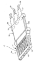
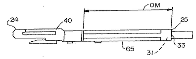
本発明は、上述したように、ケーブルウエハーコネクタに関する。このようなコネクタが図1に参照番号20で示されている。コネクタ20は、プラスチックのような電気絶縁性材料で形成された細長い本体部分22を有する。この本体部分22は、前部24及び後部25を有する。前部24は、複数の導電性信号端子43を含み、これら導電性信号端子43は、バックプレーン部材から突出するピンのアレーのような対向部材(図示せず)の対応する導電性ピンを受け入れるために予め選択された間隔で配置される。後部25は、1本以上のワイヤ28を各々含む複数のマルチワイヤケーブル27を保持する。
【0011】
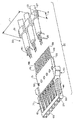
図2に示すように、ケーブル27は、それに対応するコネクタコンタクト組立体29と整列され、そしてそこに取り付けられる。コネクタ本体部分22は、コネクタコンタクト組立体29及びケーブル組立体30の一部分の上に後でモールドされる。従って、完成したコネクタ20は、2つの異なるそして個別の組立体、即ちコネクタコンタクト組立体29及びケーブル組立体30を一体化したものと考えられる。
【0012】
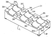
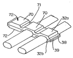
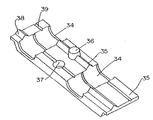
先ず、ケーブル組立体30を説明すれば、オーバーモールドに適した材料、例えば、プラスチックで形成されたケーブルクランプ即ち保持具31により、複数のマルチワイヤケーブル27が所定の間隔に保持される。図7及び図8は、このような2つのケーブルクランプ31を示す。図7に示すケーブルクランプ31は、互いに容易に係合するように構成された2つの対向する半部分32a、32bを含む。この点について、図7に示すように、ケーブルクランプの半部分32a、32bは一連の溝34を有し、ここでは、3つの溝34が、介在するランド部分35によって互いに分離されて示されている。溝34は、クランプ31の巾Wにわたって延びる。図8に示すケーブルクランプは、特定形状の外面72を有し、溝即ち谷部71が介在するランド部分70により分離されるという点で、図7の場合とは異なる。
【0013】
ランド部分35は、図示されたように、2つの半部分32a、32bを方向付けして一緒に嵌合するための手段、例えば、突出ポスト36と、このポスト36を受け入れるための対応する窪み開口37とを含むのが好ましい。これらのポスト36及び開口37は、内側の巾の広いランドに配置されるが、外側の巾の狭いランドは、三角形の突出ラグ38と、それに関連した適当な構成の三角形の溝39とを含む。これらの相互係合する素子の組は、組立中に、ケーブル27を位置保持すると共に、2つの半部分32a、32bを互いに保持するよう作用する。半部分32a、32bは、超音波溶接、プラスチック溶接、熱溶接、接着剤等の適当な手段により互いに固定されるのが好ましい。この点について、ラグ38及びそれに対応する溝39は、クランプの半部分32a、32bの適切な整列及び嵌合を確保するだけでなく、超音波溶接又は他の同様の接合手段が使用されるときにエネルギーを方向付けするようにも働く。
【0014】
重要なこととして、ケーブルクランプ31は、異なる長さのストリップで作られ、そして特定のコネクタに必要なケーブル27の本数に適合するように所望の長さLに切断される。更に、以下に詳細に述べるように、クランプ31は、型に容易に挿入されて、その上に最終的なコネクタ本体がモールドされる。コネクタ20の後端25付近の位置において、コンタクト組立体29の上に最終的なコネクタ本体がモールドされるときには、クランプ31は、ケーブル27のストレインレリーフとして働くと共に、コネクタ20の後端25の一部分を形成する助けもする。
【0015】
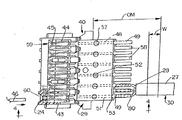
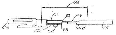
図3Aは、コネクタ20に使用されるコンタクト組立体29を示す部分断面上面図である。コンタクト組立体29は、型抜き成形された複数の個々の導電性信号端子43を支持する絶縁フレーム即ち支持部材40を備え、各導電性信号端子43は、一対のコンタクトアーム44を有し、そのコンタクト面即ちポイント45は、チャンネル59内に配置され、そしてそれに対応するピン即ち雄コンタクト部材46(仮想線で示す)の巾、厚み又は直径より小さい所定の距離だけ互いに離間される。このように、コンタクト組立体29と、同数のピン46とが係合すると、ピン46の押し込み作用のもとでコンタクトアーム44が互いに若干広げられる。コンタクトアーム44は、コンタクト面45において、それらのバネ力及び最初の至近離間構成によりピン46に係合する。コネクタ20の前端24には、支持部材40のチャンネル59に連通するスロット60が形成される。これらのスロット60は、コネクタ20の前端24に連通しそしてそこで開いており、相手コネクタ(図示せず)の導電性の雄コンタクト部材46を受け入れることができる。
【0016】
各導電性信号端子43は、後方に延びて、細長いレッグ部分48を含み、これは、テール部分49で終わる。全ての導電性信号端子43において、レッグ部分48は、隣接導電性信号端子43のレッグ部分48から分離され、単一のテール部分49が単一の導電性信号端子43に関連される。プレート部材51の形態の分離部材は、導電性信号端子43を、同数のチャンネル59内で所定の整列状態に保持するように働く。プレート部材51には開口52が設けられ、これは、プレート部材51における導電性信号端子43の適切な配置を目で確認できるようにすると共に、個々の導電性信号端子43の継続性をテストする手段も構成する。これらの「信号」導電性信号端子43のテール部分49は、プレート部材51の後面53を越えて特定の距離だけ延び、ケーブルワイヤ28のリードを対応テール部分49に終端できるようにする。
【0017】
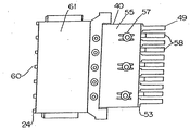
図3Bに示すように、コンタクト組立体29の反対側には、導電性プレート55の形態の接地即ちシールド部材が設けられる。この接地プレート55には、プレート部材51の反対面に配置された一連のポスト57を締りばめ等により受け入れるための一連の開口56が形成されている。接地プレート55には複数のテール部分58が形成され(接地プレート55から型抜き成形されてもよい)、これらテール部分は、プレート部材51の後面53を越えて後方に延びる。これらテール部分58は、導電性信号端子43の隣接テール部分49間の介在スペース内に延びるように所定のパターンで方向付けされる。
【0018】
接地プレート55は、更に、参照番号61で示すようにコンタクト組立体29の前面60に向かって延び、導電性信号端子43の効果的な信号分離を与える。図4に示すように、接地プレートのテール部分58は、コンタクトのテール部分49と整列され且つ好ましくはそれと同じ平面内に存在するように、若干オフセット式に曲げられる。この同一平面性が図12に示されている。この同一平面構成は、ケーブル27の個々の信号ワイヤ28及び接地シールド80の溶接又は半田付けを容易にする。更に、この同一平面構成は、導電性信号端子43間のクロストーク又は干渉を低減する。というのは、接地プレートのテール部分58及び導電性信号端子のテール部分49が同じレベルに配置され、公知の構成のように交互に上下に配置されてクロストークを誘発することがないからである。
【0019】
コネクタ20を組み立てるときには、ケーブルワイヤ28のリードを溶接又は半田付けのような適当なやり方でテール部分49、58に取り付ける。このプロセスにおいて、信号リードは、それに対応する導電性信号端子のテール部分49に取り付け、そして接地シールドは、それに対応する接地テール部分58に取り付け、交互に信号−接地−信号−接地という構成にして、適切な信号分離を確保する。図12に示すように、ケーブル27の信号ワイヤは、「S」においてコンタクトテール部分49に取り付けられ、そして接地又はドレインリードは、「G」において接地テール部分58に取り付けられる。
【0020】
ケーブルクランプ31は、コンタクト組立体29に取り付ける前にワイヤ28に取り付けられる。このように取り付けられると、クランプ31は、個々のケーブルを終端のための適切なピッチに配列する。ケーブルクランプ31は、コンタクト組立体29から離間され、それらの間に介在スペースが形成される。コンタクト組立体29のテール部分と、ケーブルワイヤ及び接地部材の終端とは、この介在スペースへと延びる。次いで、ケーブルクランプ31及びコンタクト組立体29は、全組立体として型に挿入され、そして全コネクタ本体部分22の絶縁性延長部即ちブリッジ部分65がコンタクト組立体29及びその関連プレート部材51上にオーバーモールドされる。この延長部65は、テール部分及びプレート部材51上にオーバーモールドされる。又、ケーブル組立体30及びその関連ケーブルクランプ31上にもオーバーモールドされ、それ故、ケーブルクランプ31を支持部材40に一体的に相互接続する。このオーバーモールド作業は、図3及び図4に「OM」と示された範囲で行なわれ、ケーブルワイヤ28のリード及びそれに取り付けられたテール部分49、58をカプセル状に包囲する。ブリッジ部分65をモールドする付加的な絶縁材料は、ケーブルクランプ31と支持部材40との間の介在スペースを満たし、ひいては、ケーブルワイヤ及び接地部材とテール部分49、58との終端部をカプセル状に包囲する。
【0021】
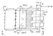
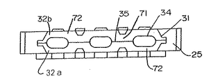
組み立てプロセス中に、ケーブルクランプ31は、ケーブル27のストレインレリーフ部材として働くと共に、型の遮蔽部としても働く。又、クランプ31は、クランプ31の後面33が型空洞に配置されて、図5に示すように型空洞の後壁と一致して延びるので、コンタクト及びケーブル組立体29、30を型空洞に適切に位置設定する助けもする。これにより形成されるコネクタ20は、ケーブルクランプ31をその本体部分22に一体化する。この一体化を助けるために、ケーブルクランプ31は、介在する溝即ち谷部分71で分離された外部ランド部分70を有してもよい。これらの谷部分71は、ケーブルクランプ31と結合するモールド材料を受け入れて、コネクタ本体部分22を構造上堅牢なものにする。更に、外部ランド部分70は、最終的なコネクタ20の全外面の一部分を形成するように働く。
本発明の好適な実施形態を図示して説明したが、当業者であれば、請求の範囲に規定された本発明の精神及び範囲から逸脱せずに種々の変更や修正がなされ得ることが明らかであろう。
【図面の簡単な説明】
【図1】本発明の原理に基づいて形成されたウエハーコネクタの斜視図である。
【図2】ウエハーサブ組立体と、このウエハーサブ組立体から分離されたケーブルクランプに保持されたワイヤケーブルとを示す分解図である。
【図3A】図2のウエハーサブ組立体にケーブルが整列されそして接触された状態を示す上面図である。
【図3B】図2のウエハーサブ組立体の下面図である。
【図4】図3の4−4線に沿った側面図である。
【図5】図1のウエハーコネクタの上面図で、ウエハーコネクタ本体内にモールドされたケーブルの位置を示す図である。
【図6】図5の6−6線に沿ったウエハーコネクタの側面図である。
【図7】図1のウエハーコネクタに使用されるケーブルクランプの一部分を示す斜視図である。
【図8】図7と同様のケーブルクランプの斜視図であるが、3本のワイヤに適用され、そしてケーブルクランプの2つの半部分を接合してケーブルを特定の位置及び間隔に維持した状態を示す図である。
【図9】図8のケーブルクランプの別の実施形態を示す図である。
【図10】本発明のウエハーコネクタに使用されるケーブルクランプの別の実施形態を示す図である。
【図11】図5の11−11線に沿ったコネクタの端面図である。
【図12】図5のコネクタの端面図であるが、コネクタの前面を示すと共に、コネクタにおける導電性信号端子及び接地コンタクトの1つの好ましい配列を概略的に示す図である。[0001]
TECHNICAL FIELD OF THE INVENTION
The present invention relates generally to cable connectors, and more particularly, to high speed electrical cable connectors with integrated strain relief means.
[0002]
[Prior art]
A number of connectors are known for connecting cables to a backplane assembly. Most of these connectors are assembled in a number of parts and include contact terminals, a ground plate and a housing. The contact terminals, ground plates, and their points of connection to the cable are maintained in different planes, as exemplified by the connector structure disclosed in U.S. Pat. No. 4,602,831 issued Jul. 29, 1986. Is done.
[0003]
[Problems to be solved by the invention]
The fact that the connection points are in different planes makes the task of welding or soldering the cable leads to the tails of the contact terminals of the connector difficult, and thus increases the manufacturing cost of the connector. Such a double plane configuration also increases the electrical interference between the signal wires of the cable in the form of crosstalk (signal leakage). Further, the strain relief members used in known connectors must be individually attached to the cable behind and spaced from the connector body.
The present invention is directed to an improved cable connector that overcomes these disadvantages.
[0004]
[Means for Solving the Problems]
Accordingly, it is an object of the present invention to provide an improved cable connector having high electrical performance characteristics for use in cable wafer connector applications.
Another object of the present invention is a connector for connecting a series of cables to an array of conductive pins, wherein the individual wires of the cable are terminated in the same plane and juxtaposed to their signal wires. Is provided to provide a connector with improved electrical performance.
[0005]
Another object of the present invention is a cable connector assembly surrounding a plurality of conductive pin contacts terminated with a large number of individual wires, wherein the wires are terminated in substantially the same plane to reduce their electrical performance. An improvement is to provide a connector assembly in which the cables are spaced by a cable locating member and the housing is molded over the locating member.
[0006]
Still another object of the present invention is to provide an integral cable connector in which a plurality of conductive signal terminals and ground contact is maintained at preselected intervals in the insulative connector housing, the tail of the conductive signal terminal The sections are maintained in alignment with each other in a single preselected plane, and the individual signal and ground wires of the series of cables are each terminated to the tail section, and the cables are separated by a preselected spacing by a clamp member. And the clamp member is to be molded integrally with the connector housing and to provide a cable connector that acts as a strain relief for the cable exiting the connector housing.
[0007]
In accordance with these objects, the present invention provides, in one primary aspect, an improved wafer connector structure having a connector body portion that supports a plurality of conductive signal terminals on one side and a ground shield on the other side. The conductive signal terminal and the ground shield have a tail extending rearward of the connector body. In a preferred embodiment, the tail portion of the conductive signal terminal is flat and extends in a common plane, while the tail portion of the ground shield is also flat, but in the same plane as the tail portion of the conductive signal terminal . Bend to extend. This coplanarity simplifies the process of attaching the cable wires to the tail.
[0008]
The tail portions of the conductive signal terminals and the ground contacts are alternately arranged, and each conductive signal terminal or a pair of the conductive signal terminals is surrounded by a ground tail portion as necessary, to reduce the possibility of crosstalk occurring in the connector. Can be reduced. Another important feature of the present invention is that the connection area of the cable wires is overmolded so that the connector housing extends from its body portion to the cable end. A cable spacer in the form of a clamp or retainer is provided, which holds the cable at a preferred spacing for cable stripping and termination.
[0009]
This cable clamp acts as a strain relief during the overmolding process and in the finished connector. The cable clamp takes the form of a two-piece insert applied to the cable, at which point a groove is formed for receiving the cable. The clamp is inserted into the mold after it is attached to the cable and the wire is terminated at the tail. An extension of the connector housing is then molded over the housing and cable wire termination points, joining the individual cable clamp and contact assemblies together into an integral connector body.
[0010]
BEST MODE FOR CARRYING OUT THE INVENTION
These and other objects, features and advantages of the present invention will be more clearly understood from the following detailed description with reference to the accompanying drawings.
The present invention, as described above, relates to a cable wafer connector. Such a connector is shown in FIG. Connector 20 has an elongated body portion 22 formed of an electrically insulating material such as plastic. The main body 22 has a
[0011]
As shown in FIG. 2,
[0012]
First, the
[0013]
The
[0014]
Importantly, the cable clamps 31 are made of strips of different lengths and are cut to the desired length L to accommodate the number of
[0015]
FIG. 3A is a partial cross-sectional top view showing a
[0016]
Each
[0017]
As shown in FIG. 3B, on the opposite side of the
[0018]
The
[0019]
When assembling the connector 20, the leads of the
[0020]
The
[0021]
During the assembly process, the
While the preferred embodiment of the invention has been illustrated and described, it will be apparent to those skilled in the art that various changes and modifications can be made without departing from the spirit and scope of the invention as defined in the appended claims. Will.
[Brief description of the drawings]
FIG. 1 is a perspective view of a wafer connector formed according to the principles of the present invention.
FIG. 2 is an exploded view showing the wafer sub-assembly and a wire cable held by a cable clamp separated from the wafer sub-assembly.
FIG. 3A is a top view showing the cables aligned and contacted with the wafer subassembly of FIG. 2;
FIG. 3B is a bottom view of the wafer subassembly of FIG.
FIG. 4 is a side view taken along the line 4-4 in FIG. 3;
FIG. 5 is a top view of the wafer connector of FIG. 1, showing a position of a cable molded in the wafer connector main body.
FIG. 6 is a side view of the wafer connector taken along line 6-6 in FIG. 5;
FIG. 7 is a perspective view showing a part of a cable clamp used in the wafer connector of FIG. 1;
FIG. 8 is a perspective view of a cable clamp similar to FIG. 7, but applied to three wires, and joining the two halves of the cable clamp to maintain the cable in a particular position and spacing. FIG.
FIG. 9 shows another embodiment of the cable clamp of FIG. 8;
FIG. 10 is a diagram showing another embodiment of the cable clamp used in the wafer connector of the present invention.
FIG. 11 is an end view of the connector along the line 11-11 in FIG. 5;
12 is an end view of the connector of FIG. 5, but showing the front of the connector and schematically illustrating one preferred arrangement of conductive signal terminals and ground contacts in the connector.
Claims (17)
更に、複数のケーブルを備え、各ケーブルは、信号ワイヤ終端をもつ少なくとも1つの信号ワイヤと、ケーブルの長さ全体にわたって延びる接地部材終端をもつ1つの接地部材とを有し、ケーブルの信号ワイヤ終端は、上記導電性信号端子のテール部分に電気的に接続され、そしてケーブルの接地部材終端は、少なくとも1つの接地部材終端が各信号ワイヤ終端に隣接する所定のパターンで上記接地コンタクト部材のテール部分に電気的に接続され、
更に、上記ケーブルに適用されそして上記支持部材の第2端の後方に離間されたクランプ部材を備え、このクランプ部材は、上記ケーブルを所定の間隔で保持し、そして
更に、コネクタハウジングを協働で画成するように上記支持部材及びクランプ部材の少なくとも一部分の上にモールドされた絶縁本体部を備え、コネクタハウジングは、上記導電性信号端子及び接地コンタクト部材のテール部分と、上記ケーブル信号ワイヤ及び接地部材の終端とをカプセル状に包囲し、これにより、上記導電性信号端子及び接地コンタクト部材のテール部分と、上記ケーブル信号ワイヤ及び接地部材の終端とを互いに絶縁することを特徴とする電気コネクタ組立体。A contact assembly including an insulative support member, a plurality of conductive signal terminals disposed on a first surface of the support member, and a ground contact member disposed on a second opposite surface of the support member; Opposing first and second ends, the conductive signal terminals are spaced apart near the first end of the support member, and the conductive signal terminals are further arranged near the second end of the support member. The ground contact member has a plurality of tail portions disposed near and extending beyond a second end of the support member, and wherein the conductive signal terminal And the tail portions of the ground contact members are arranged in a substantially common plane,
Additionally, a plurality of cables are provided, each cable having at least one signal wire having a signal wire termination and one grounding member having a grounding member termination extending the entire length of the cable, the signal wire termination of the cable. Is electrically connected to a tail portion of the conductive signal terminal , and a ground member end of the cable is a tail portion of the ground contact member with at least one ground member end in a predetermined pattern adjacent each signal wire end. Electrically connected to
The apparatus further includes a clamp member applied to the cable and spaced apart behind the second end of the support member, the clamp member holding the cable at a predetermined distance and further cooperating the connector housing. An insulating body molded over at least a portion of the support member and the clamp member to define a connector housing, the connector housing including a tail portion of the conductive signal terminal and a ground contact member, a cable signal wire and a ground. An electrical connector assembly for encapsulating the terminal end of the member, thereby insulating the conductive signal terminal and the tail portion of the ground contact member from the cable signal wire and the terminal end of the ground member. Three-dimensional.
絶縁材料で形成され、第1及び第2の面が第1及び第2の互いに逆の端間に延びているコネクタ支持部材を備え、そして
電気コンタクト組立体を更に備え、このコンタクト組立体は、上記支持部材の第1面に保持された複数の導電性であって、関連する第1テール部分を各々有する導電性信号端子と、上記支持部材の第2面に配置された共通のシールドプレートを含み、このシールドプレートには、複数の第2のテール部分が関連され、上記第1及び第2のテール部分は、上記支持部材の第2端を越えて長手方向に延び、上記シールドプレートの第2テール部分及び上記コンタクトの第1テール部分は、信号ワイヤ及び接地ワイヤに終端するために共通の平面に存在し、
更に、上記支持部材の後方でクランプ部材により離間関係に維持された複数のケーブルが接続され、各ケーブルは、一対の個別の信号ワイヤと、接地部材とを含み、上記ケーブルの信号ワイヤ及び接地部材は、上記コンタクト組立体の第1及び第2テール部分に各々接続される終端を有し、上記コンタクト組立体の第1及び第2テール部分と、上記ケーブル信号ワイヤ及び接地部材の終端とは、上記支持部材の後縁と、上記ケーブルに適用されるクランプ部材の前縁とで画成された介在スペースに向かって上記支持部材の後方に延び、上記コネクタは、更に、上記支持部材とクランプ部材を相互接続する個別のコネクタ本体部分を含み、このコネクタ本体部分は、上記介在スペースを満たすと共に、上記コンタクト組立体の第1及び第2テール部分と、上記ケーブル信号ワイヤ及び接地部材の終端とをカプセル状に包囲し、
上記コネクタ本体部分は絶縁材料で形成され、そして上記支持部材及びクランプ部材の一部分の上にモールドされる電気ケーブルコネクタ。In electric cable connectors with low interference characteristics,
A connector support member formed of an insulating material, the first and second surfaces extending between the first and second opposite ends, and further comprising an electrical contact assembly, the contact assembly comprising: a plurality of conductive held on the first surface of the support member, and the conductive signal terminals, each having a first tail portion associated, a common shielding plate disposed on the second surface of the support member A plurality of second tail portions associated with the shield plate, wherein the first and second tail portions extend longitudinally beyond a second end of the support member, and wherein the first and second tail portions extend longitudinally beyond a second end of the support member. The two tail portions and the first tail portion of the contact are in a common plane for termination to signal and ground wires;
Further, a plurality of cables maintained in a spaced relationship by a clamp member behind the support member are connected, each cable including a pair of individual signal wires and a ground member, and the signal wire and the ground member of the cable. Has ends respectively connected to first and second tail portions of the contact assembly, wherein the first and second tail portions of the contact assembly and the ends of the cable signal wires and the ground member are: The connector extends rearwardly toward an intervening space defined by a trailing edge of the support member and a leading edge of a clamp member applied to the cable, the connector further comprising: And a separate connector body portion that interconnects the first and second tapered portions of the contact assembly while filling the intervening space. A portion, a termination of the cable signal wire and grounding member enclosing the capsule shape,
The electrical cable connector wherein the connector body portion is formed of an insulating material and is molded over a portion of the support member and the clamp member.
Applications Claiming Priority (2)
| Application Number | Priority Date | Filing Date | Title |
|---|---|---|---|
| US09/461,833 US6203376B1 (en) | 1999-12-15 | 1999-12-15 | Cable wafer connector with integrated strain relief |
| US09/461,833 | 1999-12-15 |
Publications (2)
| Publication Number | Publication Date |
|---|---|
| JP2001230018A JP2001230018A (en) | 2001-08-24 |
| JP3565166B2 true JP3565166B2 (en) | 2004-09-15 |
Family
ID=23834108
Family Applications (1)
| Application Number | Title | Priority Date | Filing Date |
|---|---|---|---|
| JP2000404230A Expired - Fee Related JP3565166B2 (en) | 1999-12-15 | 2000-12-14 | Electrical cable connector |
Country Status (4)
| Country | Link |
|---|---|
| US (1) | US6203376B1 (en) |
| EP (1) | EP1109253B1 (en) |
| JP (1) | JP3565166B2 (en) |
| DE (1) | DE60021845T2 (en) |
Families Citing this family (56)
| Publication number | Priority date | Publication date | Assignee | Title |
|---|---|---|---|---|
| US6428344B1 (en) | 2000-07-31 | 2002-08-06 | Tensolite Company | Cable structure with improved termination connector |
| US6354879B1 (en) * | 2000-10-05 | 2002-03-12 | Ball Aerospace & Technologies Corp. | Connector for shielded conductors |
| US6887104B2 (en) * | 2002-11-12 | 2005-05-03 | Hon Hai Precision Ind. Co., Ltd. | Cable end connector assembly and the method of making the same |
| TW573840U (en) * | 2002-11-15 | 2004-01-21 | Hon Hai Prec Ind Co Ltd | Cable connector |
| US6955565B2 (en) * | 2002-12-30 | 2005-10-18 | Molex Incorporated | Cable connector with shielded termination area |
| US6793520B1 (en) * | 2003-03-20 | 2004-09-21 | Hon Hai Precision Ind. Co., Ltd | Cable end connector assembly with strain relief |
| US6893295B1 (en) | 2003-12-23 | 2005-05-17 | Molex Incorporated | Connector with integrated strain relief |
| US6939165B1 (en) | 2004-07-22 | 2005-09-06 | Hon Hai Precision Ind. Co., Ltd. | Cable connector assembly with cable holder |
| US7134908B2 (en) * | 2004-07-23 | 2006-11-14 | Hon Hai Precision Ind. Co., Ltd. | Single-port to multi-port cable assembly |
| USD521456S1 (en) * | 2004-11-16 | 2006-05-23 | Pent Technologies, Inc. | Female plug configuration |
| DE102005009442A1 (en) * | 2005-03-02 | 2006-09-14 | Hirschmann Automotive Gmbh | Connector with a crimp seal and / or a cable holder |
| US8013249B2 (en) * | 2006-11-24 | 2011-09-06 | Autonetworks Technologies, Ltd. | Shield conductor and shield conductor manufacturing method |
| US7485012B2 (en) * | 2007-06-28 | 2009-02-03 | Delphi Technologies, Inc. | Electrical connection system having wafer connectors |
| ATE490577T1 (en) * | 2007-10-04 | 2010-12-15 | 3M Innovative Properties Co | A SHIELD ATTACHABLE TO A CONNECTOR IN THE FIELD OF TELECOMMUNICATIONS, A COMBINATION OF THE CONNECTOR AND AT LEAST ONE SHIELD, AND METHOD FOR SHIELDING A CONNECTOR |
| US7438597B1 (en) * | 2008-04-23 | 2008-10-21 | International Business Machines Corporation | EMC clamp for three exit backshell |
| JP4565031B2 (en) * | 2008-09-17 | 2010-10-20 | 山一電機株式会社 | High-speed transmission connector, high-speed transmission connector plug, and high-speed transmission connector socket |
| US9011177B2 (en) * | 2009-01-30 | 2015-04-21 | Molex Incorporated | High speed bypass cable assembly |
| CN101483289B (en) * | 2009-02-17 | 2011-03-23 | 信音电子(中国)股份有限公司 | Assembling method for DC electric connector and DC electric connector |
| JP5293644B2 (en) * | 2010-03-02 | 2013-09-18 | 住友電装株式会社 | Wiring harness wiring structure |
| JP5212499B2 (en) * | 2010-09-08 | 2013-06-19 | 第一精工株式会社 | Electrical connector and manufacturing method thereof |
| JP5640912B2 (en) * | 2011-07-01 | 2014-12-17 | 山一電機株式会社 | Contact unit and printed circuit board connector including the same |
| CN103515749A (en) * | 2012-06-19 | 2014-01-15 | 凡甲电子(苏州)有限公司 | A terminal module group and a cable connector assembly with the terminal module group |
| WO2014031851A1 (en) | 2012-08-22 | 2014-02-27 | Amphenol Corporation | High-frequency electrical connector |
| US9142921B2 (en) | 2013-02-27 | 2015-09-22 | Molex Incorporated | High speed bypass cable for use with backplanes |
| JP6170619B2 (en) | 2013-07-10 | 2017-07-26 | モレックス エルエルシー | Wafer connector with ground clamp |
| CN105580210B (en) | 2013-09-04 | 2017-07-07 | 莫列斯有限公司 | Connector system with bypass cable |
| EP2854239B1 (en) * | 2013-09-25 | 2019-11-13 | Virginia Panel Corporation | High speed data module for high life cycle interconnect device |
| CN104022399B (en) * | 2014-05-29 | 2016-06-22 | 立讯精密工业(昆山)有限公司 | Pin connector |
| TW201613203A (en) * | 2014-09-29 | 2016-04-01 | Foxconn Interconnect Technology Ltd | Electrical connector assembly and assembling method of the same |
| CN111641084B (en) | 2014-11-12 | 2022-05-24 | 安费诺有限公司 | Very high speed, high density electrical interconnect system with impedance control in the mating region |
| WO2016112384A1 (en) | 2015-01-11 | 2016-07-14 | Molex, Llc | Wire to board connectors suitable for use in bypass routing assemblies |
| JP6517349B2 (en) | 2015-01-11 | 2019-05-22 | モレックス エルエルシー | Circuit board bypass assembly and components thereof |
| US10739828B2 (en) | 2015-05-04 | 2020-08-11 | Molex, Llc | Computing device using bypass assembly |
| CN108713355B (en) | 2016-01-11 | 2020-06-05 | 莫列斯有限公司 | Routing components and systems using routing components |
| US10424878B2 (en) | 2016-01-11 | 2019-09-24 | Molex, Llc | Cable connector assembly |
| CN108475870B (en) | 2016-01-19 | 2019-10-18 | 莫列斯有限公司 | Integrated Routing Components and Systems Using Integrated Routing Components |
| CN109565137A (en) | 2016-05-31 | 2019-04-02 | 安费诺有限公司 | High-performance cable termination device |
| WO2018075777A1 (en) | 2016-10-19 | 2018-04-26 | Amphenol Corporation | Compliant shield for very high speed, high density electrical interconnection |
| TWI790268B (en) | 2017-08-03 | 2023-01-21 | 美商安芬諾股份有限公司 | Connector for low loss interconnection system and electronic system comprising the same |
| CN114421199A (en) | 2017-11-14 | 2022-04-29 | 申泰公司 | data communication system |
| US10665973B2 (en) | 2018-03-22 | 2020-05-26 | Amphenol Corporation | High density electrical connector |
| CN112514175B (en) | 2018-04-02 | 2022-09-09 | 安达概念股份有限公司 | Controlled Impedance Compliant Cable Terminations |
| US10790619B2 (en) * | 2018-07-12 | 2020-09-29 | Cinch Connectors, Inc. | Shielded cable system for the shielding and protection against emi-leakage and impedance control |
| CN114980508B (en) | 2018-09-04 | 2026-01-23 | 申泰公司 | Ultra-high density low profile edge card connector |
| US10931062B2 (en) | 2018-11-21 | 2021-02-23 | Amphenol Corporation | High-frequency electrical connector |
| CN117175239A (en) | 2019-01-25 | 2023-12-05 | 富加宜(美国)有限责任公司 | Socket connector and electric connector |
| WO2020154526A1 (en) | 2019-01-25 | 2020-07-30 | Fci Usa Llc | I/o connector configured for cabled connection to the midboard |
| US11437762B2 (en) | 2019-02-22 | 2022-09-06 | Amphenol Corporation | High performance cable connector assembly |
| US10873160B2 (en) * | 2019-05-06 | 2020-12-22 | Te Connectivity Corporation | Receptacle assembly having cabled receptacle connector |
| EP4032147A4 (en) | 2019-09-19 | 2024-02-21 | Amphenol Corporation | High speed electronic system with midboard cable connector |
| CN115428275B (en) | 2020-01-27 | 2025-12-30 | 富加宜(美国)有限责任公司 | High-speed connector |
| US11469553B2 (en) | 2020-01-27 | 2022-10-11 | Fci Usa Llc | High speed connector |
| CN113258325A (en) | 2020-01-28 | 2021-08-13 | 富加宜(美国)有限责任公司 | High-frequency middle plate connector |
| WO2022094467A1 (en) | 2020-11-02 | 2022-05-05 | Samtec, Inc. | Flex circuit and electrical communication assemblies related to same |
| USD1002553S1 (en) | 2021-11-03 | 2023-10-24 | Amphenol Corporation | Gasket for connector |
| US11876363B2 (en) * | 2022-02-11 | 2024-01-16 | Eric Wilfred Moore | Audio video cable holder |
Family Cites Families (12)
| Publication number | Priority date | Publication date | Assignee | Title |
|---|---|---|---|---|
| US4580869A (en) | 1980-08-04 | 1986-04-08 | Star-Tron Corporation | Connector and method of making it |
| US4602831A (en) | 1983-09-26 | 1986-07-29 | Amp Incorporated | Electrical connector and method of making same |
| US4615578A (en) * | 1984-12-05 | 1986-10-07 | Raychem Corporation | Mass termination device and connection assembly |
| US4767352A (en) | 1986-08-28 | 1988-08-30 | Minnesota Mining And Manufacturing Company | Integrally molded cable termination assembly, contact and method |
| US4860445A (en) | 1989-02-09 | 1989-08-29 | Gte Products Corporation | Method of mounting electrical contacts in connector body |
| US5100347A (en) * | 1989-05-03 | 1992-03-31 | E. I. Du Pont De Nemours And Company | Method and apparatus for providing a cable assembly seal and strain relief |
| US4976628A (en) * | 1989-11-01 | 1990-12-11 | Amp Incorporated | Modules for cable assemblies |
| US5038001A (en) | 1990-03-13 | 1991-08-06 | Amp Incorporated | Feature for orientation of an electrical cable |
| US5281762A (en) * | 1992-06-19 | 1994-01-25 | The Whitaker Corporation | Multi-conductor cable grounding connection and method therefor |
| JP3415889B2 (en) * | 1992-08-18 | 2003-06-09 | ザ ウィタカー コーポレーション | Shield connector |
| US5328386A (en) * | 1993-06-08 | 1994-07-12 | Frantz Robert H | Wire organizer for ballast connector |
| US5806179A (en) | 1996-02-20 | 1998-09-15 | Alps Electric (Usa), Inc. | Method for connecting a cable to a printed circuit board |
-
1999
- 1999-12-15 US US09/461,833 patent/US6203376B1/en not_active Expired - Lifetime
-
2000
- 2000-12-07 EP EP00126826A patent/EP1109253B1/en not_active Expired - Lifetime
- 2000-12-07 DE DE60021845T patent/DE60021845T2/en not_active Expired - Fee Related
- 2000-12-14 JP JP2000404230A patent/JP3565166B2/en not_active Expired - Fee Related
Also Published As
| Publication number | Publication date |
|---|---|
| US6203376B1 (en) | 2001-03-20 |
| DE60021845T2 (en) | 2006-01-26 |
| DE60021845D1 (en) | 2005-09-15 |
| EP1109253B1 (en) | 2005-08-10 |
| EP1109253A3 (en) | 2003-11-26 |
| JP2001230018A (en) | 2001-08-24 |
| EP1109253A2 (en) | 2001-06-20 |
Similar Documents
| Publication | Publication Date | Title |
|---|---|---|
| JP3565166B2 (en) | Electrical cable connector | |
| TWI817130B (en) | Mating module and cable connector | |
| JP2589135B2 (en) | Electrical connector | |
| TWI840661B (en) | Electrical connector assembly | |
| EP1964216B1 (en) | Connector family for board mounting and cable applications | |
| JP2525660B2 (en) | Electrical connector assembly and termination cover used therefor | |
| US6273758B1 (en) | Wafer connector with improved grounding shield | |
| US9991639B2 (en) | Wafer connector with grounding clamp | |
| US5378161A (en) | Tapered electrical connector | |
| US6893295B1 (en) | Connector with integrated strain relief | |
| US6840798B2 (en) | Shielding connector, a shielding connector system, a terminal fitting and use thereof | |
| JP2579149B2 (en) | Electrical connector | |
| JP3296731B2 (en) | Cable connector assembly and method of manufacturing the same | |
| CN1069450C (en) | Connector for electric cable | |
| CN110808493B (en) | Electrical connector | |
| US5085595A (en) | Side entry cable assembly | |
| JP2992689B2 (en) | Male connector | |
| JPH0773924A (en) | Electrical connector | |
| JP2000507384A (en) | High density electrical connector | |
| JP2686652B2 (en) | Electric connector for multi-core coaxial cable and its connection method | |
| US6672913B1 (en) | Plug connector and method for manufacturing the same | |
| US6179669B1 (en) | Molded receptacle for a daisy chain power cord assembly | |
| US6325681B1 (en) | Cable connector and contacts for cable connector | |
| EP1120867A2 (en) | High speed, shielded cable assembly | |
| JP3728424B2 (en) | Wire connection type connector |
Legal Events
| Date | Code | Title | Description |
|---|---|---|---|
| A521 | Written amendment |
Free format text: JAPANESE INTERMEDIATE CODE: A523 Effective date: 20040127 |
|
| A01 | Written decision to grant a patent or to grant a registration (utility model) |
Free format text: JAPANESE INTERMEDIATE CODE: A01 Effective date: 20040309 |
|
| R155 | Notification before disposition of declining of application |
Free format text: JAPANESE INTERMEDIATE CODE: R155 |
|
| A61 | First payment of annual fees (during grant procedure) |
Free format text: JAPANESE INTERMEDIATE CODE: A61 Effective date: 20040531 |
|
| R150 | Certificate of patent or registration of utility model |
Free format text: JAPANESE INTERMEDIATE CODE: R150 |
|
| FPAY | Renewal fee payment (event date is renewal date of database) |
Free format text: PAYMENT UNTIL: 20080618 Year of fee payment: 4 |
|
| FPAY | Renewal fee payment (event date is renewal date of database) |
Free format text: PAYMENT UNTIL: 20090618 Year of fee payment: 5 |
|
| FPAY | Renewal fee payment (event date is renewal date of database) |
Free format text: PAYMENT UNTIL: 20100618 Year of fee payment: 6 |
|
| FPAY | Renewal fee payment (event date is renewal date of database) |
Free format text: PAYMENT UNTIL: 20100618 Year of fee payment: 6 |
|
| FPAY | Renewal fee payment (event date is renewal date of database) |
Free format text: PAYMENT UNTIL: 20110618 Year of fee payment: 7 |
|
| FPAY | Renewal fee payment (event date is renewal date of database) |
Free format text: PAYMENT UNTIL: 20120618 Year of fee payment: 8 |
|
| LAPS | Cancellation because of no payment of annual fees |