JP3564397B2 - sewing machine - Google Patents
sewing machine Download PDFInfo
- Publication number
- JP3564397B2 JP3564397B2 JP2000615445A JP2000615445A JP3564397B2 JP 3564397 B2 JP3564397 B2 JP 3564397B2 JP 2000615445 A JP2000615445 A JP 2000615445A JP 2000615445 A JP2000615445 A JP 2000615445A JP 3564397 B2 JP3564397 B2 JP 3564397B2
- Authority
- JP
- Japan
- Prior art keywords
- bed
- opening
- sewing machine
- arm
- processing unit
- Prior art date
- Legal status (The legal status is an assumption and is not a legal conclusion. Google has not performed a legal analysis and makes no representation as to the accuracy of the status listed.)
- Expired - Lifetime
Links
- 238000009958 sewing Methods 0.000 title claims description 46
- 239000000463 material Substances 0.000 claims description 25
- 230000005540 biological transmission Effects 0.000 claims description 13
- 230000000630 rising effect Effects 0.000 claims description 4
- 238000007689 inspection Methods 0.000 description 7
- 238000009434 installation Methods 0.000 description 5
- 238000003466 welding Methods 0.000 description 4
- 239000011347 resin Substances 0.000 description 2
- 229920005989 resin Polymers 0.000 description 2
- 238000000034 method Methods 0.000 description 1
Images


Classifications
-
- D—TEXTILES; PAPER
- D05—SEWING; EMBROIDERING; TUFTING
- D05B—SEWING
- D05B73/00—Casings
-
- D—TEXTILES; PAPER
- D05—SEWING; EMBROIDERING; TUFTING
- D05B—SEWING
- D05B75/00—Frames, stands, tables, or other furniture adapted to carry sewing machines
- D05B75/02—Frames, stands, tables, or other furniture adapted to carry sewing machines for drop-head sewing machines
-
- D—TEXTILES; PAPER
- D05—SEWING; EMBROIDERING; TUFTING
- D05B—SEWING
- D05B77/00—Covers, or portable enclosures, for sewing machines
Landscapes
- Engineering & Computer Science (AREA)
- Textile Engineering (AREA)
- Sewing Machines And Sewing (AREA)
Description
技術分野
本発明はミシンに関する。詳しくは、上下2段に亘って素材を送るためのベッドを有し、上段側ベッドの片側の端部から先上がり姿勢で傾斜アームが立ち上げられ、その傾斜アームから横行アームが延び出し、その横行アームの先端部に、縫製用や溶着用といった素材の接合に必要な機構が取り付けられるようになっているミシンに関する。
背景技術
図4に今般開発したミシンの一部破断した外観概略斜視図を示してある。このミシンは、平面視矩形の共通のベース1に形成された上下2段に亘るベッド2,3を有している。これらのベッド2,3は、その横方向(左右方向に一致する。以下同じ)の一端部同士がベース1の左端部12で連設されているのに対し、その横方向他端部の相互間に開放口13を形成している。また、ベース1には、各段のベッド2,3の前方部位に処理部4が設けられている。図例のミシンは縫製仕様であるため、上記処理部4によって送り歯を備えた針落ち部が形成されている。
一方、上段側ベッド3の横方向他端部から中空で断面形状が略四角形の傾斜アーム5が立ち上がっている。この傾斜アーム5は、その下端部51が上段側ベッド3に連設されていると共に、下段側ベッド2の素材出口21の上を越えて上記処理部4の右側方上部にまで延び出た先上がり姿勢になっている。また、この傾斜アーム5には、その先端部から上記処理部4に近づく横方向(図例では左方向)に延び出た横行アーム6が連設されている。そして、この横行アーム6の先端部によって形成されたヘッド7に、縫い針やその取付け杆といった作動機構(不図示)が設けられるようになっていて、その作動機構が上記処理部4と共働して素材の接合に必要な動作を行うようになっている。
このミシンは、下段側ベッド2の上を送る素材を開放口13を通してベース1の右側に垂らし、上段側ベッド3の上を送る素材をベース1の左側に垂らした状態で、それらの素材の各端部を処理部4に送り込むことができるので、処理し得る素材の横幅に制限がなくなって幅の広い素材を接合処理することができるという長所を持っている。
ところで、このミシンは、横行アーム6と傾斜アーム5と上段側ベッド3と下段側ベッド2とによって形作られる正面視形状がZ形ないしS形に見えるので、Z形ミシンあるいはS形ミシンと通称されることがある。
このミシンにおいて、ベース1や上下各段のベッド2,3は、図4に一部破断して示したように、下面が開放した中空形に形成されており、傾斜アーム5や横行アーム6などは中空の筒形に形成されていて、それらの各内部スペースが、上記処理部4や上記作動機構に動力を伝達するためのシャフト、シャフト同士を連結している関節機構、その他の必要な動力伝達要素を配備するための設置スペースとして利用されている。
このミシンは所定高さの架台9上に載架されていて、作業現場への搬入性や移動時の取扱性、縫製作業性などが高められている。また、ベース1の後部に設けられた支軸14が架台9に設けられたブラケット91に回転可能に支持されていて、上記した動力伝達要素の点検や補修を行うときには、ベース1が支軸14を中心にして上方へ回動されてそのベース1の内部が手前側から見えるような姿勢に保持され、その状態で動力伝達要素の点検や補修を行うようにしている。
ところが、そのような姿勢にベース1を保持した場合、傾斜アーム5の内部は、上下各段のベッド2.3の開放口13を通してかろうじて見えるだけであるので、傾斜アーム5の内部スペースに配備されているシャフトなどの動力伝達要素を点検しにくいという問題があった。
また、傾斜アーム5の内部スペースに配備されているシャフトなどの動力伝達要素を点検したり補修したり交換したりする場合には、狭い開放口13から工具を傾斜アーム5の内部に差し入れる必要があったので、その補修や交換の作業が非常に行いにくいという問題があった。
発明の開示
本発明は以上の問題に鑑みてなされたものである。
したがって、本発明の目的は、上記したZ形ミシンあるいはS形ミシンと通称するミシンにおいて、中空の傾斜アームの内部スペースに配備されている動力伝達要素の点検や補修、交換などを容易に行うことができるようにすることである。
本発明は、横方向一端部同士が連設されかつ横方向他端部に開放口を形成する上下2段に亘る下面開放の中空のベッドと、各段のベッドの前方部位に設けられかつ上段側ベッド及び下段側ベッドのそれぞれの上を送られてきた各別の素材を互いに接合するための処理部と、上段側ベッドの横方向他端部から立ち上げられかつ下段側ベッドの素材出口の上を越えて上記処理部の側方上部にまで延び出た先上がり姿勢の傾斜アームと、この傾斜アームの先端部から上記処理部に近づく横方向に延び出しかつ先端部に上記処理部と共働して各別の上記素材を接合するための作動機構が設けられる横行アームと、を備えたミシンを対象としている。
このミシンは、上記したZ形ミシンあるいはS形ミシンと通称するミシンである。そのため、上述したように、処理し得る素材の横幅に制限がなくなって幅の広い素材を接合処理することができるという長所を持っている。
本発明に係るミシンは、下段側ベッドに開設され、かつ、中空で内部スペースが動力伝達要素の設置スペースとして形成された上記傾斜アームの内部に上段側ベッドの内部スペースを通して工具を差し入れることのできる開口を有している。
このようになっていると、下段側ベッドの開口から上段側ベッドの内部スペースを通して無理なく傾斜アームの内部を覗き込んだり、傾斜アームの内部に工具を差し入れたりすることができるので、上下各段のベッドによって形成されている狭い開放口から傾斜アームの内部スペースに工具を差し入れるのに比べて作業性が格段に向上する。したがって、傾斜アームの内部スペースに配備されているシャフトや関節機構といった動力伝達要素の点検や補修、交換を格段に容易に行うことができるようになる。
本発明では、上段側ベッドと下段側ベッドとが共通のベースに設けられており、このベースが、上記下段側ベッドを起き上がらせて上記開口を手前側に向ける開放姿勢と、上記下段側ベッドが架台上に載架される設置姿勢との間で起倒可能に上記架台に取り付けられていることが望ましい。
このようになっていると、ベースを開放姿勢にすることによって開口が手前側に向くようになるので、当該ミシンの手前側(前側)に作業者が位置して無理のない姿勢で傾斜アームの内部スペースに配備されている動力伝達要素の点検や補修、交換を行うことができるようになる。
本発明では、上記開口に着脱される閉鎖板を有していることが望ましい。このものによると、閉鎖板を開口に装着しておくことによって、下段側ベッドの上で素材を送るときに、開口がじゃまにならない。
【図面の簡単な説明】
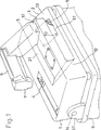
図1は本発明に係るミシンの実施形態を一部破断して示した概略斜視図である。
図2は本発明に係るミシンの実施形態を示した概略側面図である。
図3は点検や補修などを行う場合を説明するための概略側面図である。
図4は今般開発したミシンを一部破断して示した外観概略斜視図である。
発明を実施するための最良の形態
図1に示したミシンでは、同図に一部破断して示したように、下段側ベッド2に開口8が開設されており、この開口8に閉鎖板81が着脱可能になっている。これ以外の事項は、図4で説明したミシンと同様である。たとえば、ベース1や上下各段のベッド2.3は、下面が開放した中空形に形成されている点(図4の破断部参照)、傾斜アーム5や横行アーム6などが中空の筒形に形成されていて、それらの各内部スペースが、上記処理部4や上記作動機構に動力を伝達するためのシャフト、シャフト同士を連結している関節機構、その他の必要な動力伝達要素を配備するための設置スペースとして利用されている点などが同じである。したがって、図4と同一部分には同一符号を付して詳細な説明を省略することにする。
したがって、このミシンによると、図2のように、下段側ベッド2の上を送る素材F1を開放口13(図1参照)を通してベース1の右側に垂らし、上段側ベッド3の上を送る素材F2をベース1の左側に垂らした状態で、それらの素材の各端部を処理部4に送り込むことができるので、処理し得る素材の横幅に制限がなくなって幅の広い素材を接合処理することができる。
下段側ベッド3に開設されている開口8は、傾斜アーム5の下端部51の下方に位置している。そのため、ベース1の裏側からその開口8を通して傾斜アーム5の内部スペースを除き見ることが可能である。また、開口8は、その開口8と上段側ベッド3の内部スペースを通して傾斜アーム5の内部にスパナなどの点検や補修、交換などに際して用いられる工具を差し入れることのできる大きさを有している。開口8の好ましい大きさは、点検や補修・交換などを行う作業者の腕を無理なく差し入れることのできる大きさである。
図1のように、閉鎖板81は、開口8と同じような矩形に形成されていて、その四隅を取付けねじ82…を用いて下段側ベッド2に固定することによって、開口8を塞ぎ、かつ、その上面が上段側ベッド2の上面と面一になる。また、取付けねじ82を取り外すことによって下段側ベッド2から離脱され、開口8を開放し得るようになっている。
図1のように、ベース1はその後部の支軸14が架台9側のブラケット91に回転可能に支持されている。そして、ベース1を支軸14を中心に上方へ回転させることによって図3のように開放姿勢にすると、下段側ベッド2が起き上がって開口8が手前側(当該ミシンの前側)に向く。また、ベース1を図1のように設置姿勢にすると、下段側ベッド2が架台9上に載架される。
このミシンにおいて、図3のようにベース1を開放姿勢にすると、下段側ベッド2の開口8が手前側に向くので、当該ミシンの手前側(前側)に作業者が位置して無理のない姿勢で破線矢印Eの方向から傾斜アーム5の内部スペースを無理なく覗き込んだり、あるいは、開口8から上段側ベッド3の内部スペースを通して傾斜アーム6の内部スペースに工具を差し入れて、その傾斜アームの内部に配備されている動力伝達要素の点検や補修、交換を無理なく行うことができる。
また、図1のように開口8に閉鎖板81を装着しておくと、開口8が塞がれて下段側ベッド2の上面と閉鎖板81の上面とが面一になるので、図2のように下段側ベッド2の上で素材F1を送るときに、開口8や閉鎖板81がじゃまにならない。
図例では縫製仕様のミシンを示してある。そのため、処理部4が、送り歯を備えた針落ち部として形成されている。また、ヘッド7に取り付けられて処理部4と共働して各別の素材F1,F2を接合するための作動機構としては、縫い針やその取付け杆、それらを動作させるための駆動系が採用される。しかし、本発明は、縫製仕様以外のミシン、たとえば樹脂シートを溶着して接合するための溶着仕様のミシンにも適用することが可能であり、その場合には、処理部4や作動機構が、樹脂シートの溶着に必要なヒートローラや押えローラ、それらの駆動系などによって構成される。
産業上の利用可能性
以上のように、本発明によれば、下段側ベッドに開口を開設するというきわめて簡単な構成によって、傾斜アームの内部スペースに配備されている動力伝達要素の点検や補修、交換といった作業を無理なく行うことができるようになる。また、開口に閉鎖板を着脱できるようにしておくことによって、開口にじゃまされずに素材の接合処理を円滑に行うことができるようになる。TECHNICAL FIELD The present invention relates to a sewing machine. Specifically, the bed has a bed for feeding the material over the upper and lower two stages, the inclined arm is raised from one end of the upper side bed in a rising position, the traversing arm extends from the inclined arm, and The present invention relates to a sewing machine in which a mechanism required for joining materials such as sewing and welding is attached to a distal end of a traversing arm.
2. Description of the Related Art FIG. 4 is a schematic perspective view of the recently developed sewing machine with a partially broken appearance. This sewing machine has
On the other hand, an
The sewing machine hangs the material to be fed on the
By the way, this sewing machine is generally called a Z-shaped sewing machine or an S-shaped sewing machine because a front view shape formed by the traversing
In this sewing machine, the base 1 and the upper and
The sewing machine is mounted on a
However, when the base 1 is held in such a posture, the inside of the
In addition, when inspecting, repairing, or replacing a power transmission element such as a shaft provided in the internal space of the
DISCLOSURE OF THE INVENTION The present invention has been made in view of the above problems.
Accordingly, an object of the present invention is to easily perform inspection, repair, replacement, and the like of a power transmission element provided in an inner space of a hollow inclined arm in a sewing machine commonly referred to as a Z-type sewing machine or an S-type sewing machine described above. Is to be able to
The present invention is directed to a hollow bed having two open bottoms, one end in the horizontal direction being continuous with the other end in the horizontal direction, and an open mouth at the other end. A processing unit for joining different materials sent on the upper bed and the lower bed to each other, and a material outlet of the lower bed which is raised from the other lateral end of the upper bed. A slanting arm in a raised position extending over the upper side to the upper side of the processing unit, and extending from the distal end of the inclined arm in a lateral direction approaching the processing unit and having the distal end shared with the processing unit. And a traversing arm provided with an operating mechanism for operating and joining each of the different materials.
This sewing machine is a sewing machine commonly referred to as the Z-type sewing machine or the S-type sewing machine described above. For this reason, as described above, there is an advantage that there is no limit on the width of the material that can be processed, and a wide material can be joined.
The sewing machine according to the present invention is characterized in that a tool is inserted through the inner space of the upper bed into the inside of the inclined arm formed in the lower bed and having a hollow inner space formed as an installation space for the power transmission element. It has an opening that can be made.
With this configuration, it is possible to easily look into the inside of the inclined arm from the opening of the lower bed through the internal space of the upper bed, and insert tools into the interior of the inclined arm. Workability is significantly improved as compared with inserting a tool through the narrow opening formed by the bed into the internal space of the inclined arm. Therefore, inspection, repair, and replacement of the power transmission elements such as the shaft and the joint mechanism provided in the internal space of the inclined arm can be performed much easier.
In the present invention, the upper bed and the lower bed are provided on a common base, and the base has an open position in which the lower bed is raised and the opening is directed toward the near side, and the lower bed is It is desirable to be attached to the above-mentioned gantry so that it can be turned upside down between the installation posture mounted on the gantry.
With this configuration, the opening is directed toward the near side by setting the base to the open position, so that the worker is positioned on the near side (front side) of the sewing machine and the inclined arm is positioned in a comfortable position. Inspection, repair, and replacement of the power transmission element provided in the internal space can be performed.
In the present invention, it is desirable to have a closing plate detachably attached to the opening. According to this, the opening is not obstructed when the material is fed on the lower bed by attaching the closing plate to the opening.
[Brief description of the drawings]
FIG. 1 is a schematic perspective view showing an embodiment of a sewing machine according to the present invention, partially cut away.
FIG. 2 is a schematic side view showing an embodiment of the sewing machine according to the present invention.
FIG. 3 is a schematic side view for explaining a case where inspection, repair, and the like are performed.
FIG. 4 is a schematic perspective view showing the appearance of the recently developed sewing machine with a part cut away.
BEST MODE FOR CARRYING OUT THE INVENTION In the sewing machine shown in FIG. 1, an opening 8 is opened in the
Therefore, according to this sewing machine, as shown in FIG. 2, the material F1 to be fed on the
The opening 8 formed in the
As shown in FIG. 1, the closing plate 81 is formed in a rectangular shape similar to the opening 8, and the four corners are fixed to the
As shown in FIG. 1, the
In this sewing machine, when the base 1 is in the open position as shown in FIG. 3, the opening 8 of the
When the closing plate 81 is attached to the opening 8 as shown in FIG. 1, the opening 8 is closed and the upper surface of the
In the illustrated example, a sewing machine of a sewing specification is shown. For this reason, the processing section 4 is formed as a needle drop section having a feed dog. As an operating mechanism attached to the
INDUSTRIAL APPLICABILITY As described above, according to the present invention, the inspection and repair of the power transmission elements disposed in the internal space of the inclined arm, according to the extremely simple configuration of opening the lower bed, Work such as replacement can be performed without difficulty. In addition, by allowing the closing plate to be attached to and detached from the opening, the joining process of the materials can be smoothly performed without being hindered by the opening.
Claims (4)
下段側ベッドに開設され、かつ、中空で内部スペースが動力伝達要素の設置スペースとして形成された上記傾斜アームの内部に上段側ベッドの内部スペースを通して工具を差し入れることのできる開口を有することを特徴とするミシン。A hollow bed having one lower end open in the upper and lower tiers extending upward and downward from two lower tiers having one end in the horizontal direction and forming an opening at the other end in the horizontal direction; A processing unit for joining the different materials that have been sent over each of the side beds to each other, and rising from the other lateral end of the upper bed and passing over the material outlet of the lower bed A slanting arm in a rising position extending to the upper side of the processing unit; and a laterally extending arm approaching the processing unit from a distal end of the inclined arm and cooperating with the processing unit at the distal end. A traversing arm provided with an operating mechanism for joining another material,
Opening in the lower bed, and having an opening through which a tool can be inserted through the internal space of the upper bed inside the inclined arm, which is hollow and has an internal space formed as a space for installing a power transmission element. Sewing machine.
Applications Claiming Priority (1)
| Application Number | Priority Date | Filing Date | Title |
|---|---|---|---|
| PCT/JP1999/002275 WO2000066827A1 (en) | 1999-04-28 | 1999-04-28 | Sewing machine |
Publications (2)
| Publication Number | Publication Date |
|---|---|
| JPWO2000066827A1 JPWO2000066827A1 (en) | 2002-12-03 |
| JP3564397B2 true JP3564397B2 (en) | 2004-09-08 |
Family
ID=14235579
Family Applications (1)
| Application Number | Title | Priority Date | Filing Date |
|---|---|---|---|
| JP2000615445A Expired - Lifetime JP3564397B2 (en) | 1999-04-28 | 1999-04-28 | sewing machine |
Country Status (3)
| Country | Link |
|---|---|
| JP (1) | JP3564397B2 (en) |
| KR (1) | KR100387127B1 (en) |
| WO (1) | WO2000066827A1 (en) |
Family Cites Families (3)
| Publication number | Priority date | Publication date | Assignee | Title |
|---|---|---|---|---|
| JPH0354705Y2 (en) * | 1984-10-11 | 1991-12-03 | ||
| JPH0349662Y2 (en) * | 1988-11-15 | 1991-10-23 | ||
| JPH0928968A (en) * | 1995-07-18 | 1997-02-04 | Juki Corp | Sewing machine safety equipment |
-
1999
- 1999-04-28 JP JP2000615445A patent/JP3564397B2/en not_active Expired - Lifetime
- 1999-04-28 KR KR10-2000-7013678A patent/KR100387127B1/en not_active Expired - Lifetime
- 1999-04-28 WO PCT/JP1999/002275 patent/WO2000066827A1/en not_active Ceased
Also Published As
| Publication number | Publication date |
|---|---|
| KR20010052532A (en) | 2001-06-25 |
| KR100387127B1 (en) | 2003-06-12 |
| WO2000066827A1 (en) | 2000-11-09 |
Similar Documents
| Publication | Publication Date | Title |
|---|---|---|
| US7587922B2 (en) | Hemming machine and inspecting method thereof | |
| EP0842315B1 (en) | Method and device for producing a hollow body, in particular a textile hollow body | |
| WO2017173740A1 (en) | Computer numerical control machine for manipulator-based fully automated material loading and unloading | |
| KR20170124393A (en) | Laser Processing Apparatus of interior material for automobile | |
| JP3564397B2 (en) | sewing machine | |
| JPH0666Y2 (en) | Work cloth holding device | |
| JP2001025592A (en) | Sewing machine cloth cutting device | |
| KR100882749B1 (en) | Fixing bracket welding device for vehicles | |
| EP3075519A1 (en) | Bonding device | |
| JP6910941B2 (en) | Screw feed / tightening unit for continuous screw tightening machine | |
| CN100507124C (en) | Cloth cutter of circular buttonhole machine | |
| TWI639543B (en) | Robot and its operation method | |
| US6662737B2 (en) | Mattress label sewing clamp | |
| JPWO2000066827A1 (en) | sewing machine | |
| KR101218716B1 (en) | Pocket Setter | |
| JP3415766B2 (en) | Automatic sewing device for sewing flaps on workpieces | |
| JP5101835B2 (en) | Cylindrical frame for embroidery processing | |
| JP2003181172A (en) | Bead sewing machine | |
| JP4913373B2 (en) | Sewing needle drive mechanism | |
| JP5059688B2 (en) | Sewing sewing machine | |
| CN208830007U (en) | A kind of automatic turning rib knitting machine | |
| JP2006062229A (en) | Paper box manufacturing equipment | |
| KR101241008B1 (en) | Head device for friction stir welding mechine | |
| JP5252865B2 (en) | Opening and closing mechanism of the hopper of the medicine packaging machine | |
| EP1247625A3 (en) | Device for forming box joining flaps in a box blanks splitting machine |
Legal Events
| Date | Code | Title | Description |
|---|---|---|---|
| TRDD | Decision of grant or rejection written | ||
| A01 | Written decision to grant a patent or to grant a registration (utility model) |
Free format text: JAPANESE INTERMEDIATE CODE: A01 Effective date: 20040511 |
|
| A61 | First payment of annual fees (during grant procedure) |
Free format text: JAPANESE INTERMEDIATE CODE: A61 Effective date: 20040607 |
|
| R150 | Certificate of patent or registration of utility model |
Free format text: JAPANESE INTERMEDIATE CODE: R150 |
|
| FPAY | Renewal fee payment (event date is renewal date of database) |
Free format text: PAYMENT UNTIL: 20080611 Year of fee payment: 4 |
|
| FPAY | Renewal fee payment (event date is renewal date of database) |
Free format text: PAYMENT UNTIL: 20090611 Year of fee payment: 5 |
|
| FPAY | Renewal fee payment (event date is renewal date of database) |
Free format text: PAYMENT UNTIL: 20100611 Year of fee payment: 6 |
|
| FPAY | Renewal fee payment (event date is renewal date of database) |
Free format text: PAYMENT UNTIL: 20110611 Year of fee payment: 7 |
|
| FPAY | Renewal fee payment (event date is renewal date of database) |
Free format text: PAYMENT UNTIL: 20110611 Year of fee payment: 7 |
|
| FPAY | Renewal fee payment (event date is renewal date of database) |
Free format text: PAYMENT UNTIL: 20110611 Year of fee payment: 7 |
|
| FPAY | Renewal fee payment (event date is renewal date of database) |
Free format text: PAYMENT UNTIL: 20120611 Year of fee payment: 8 |
|
| FPAY | Renewal fee payment (event date is renewal date of database) |
Free format text: PAYMENT UNTIL: 20120611 Year of fee payment: 8 |
|
| FPAY | Renewal fee payment (event date is renewal date of database) |
Free format text: PAYMENT UNTIL: 20130611 Year of fee payment: 9 |
|
| FPAY | Renewal fee payment (event date is renewal date of database) |
Free format text: PAYMENT UNTIL: 20130611 Year of fee payment: 9 |
|
| R250 | Receipt of annual fees |
Free format text: JAPANESE INTERMEDIATE CODE: R250 |
|
| R250 | Receipt of annual fees |
Free format text: JAPANESE INTERMEDIATE CODE: R250 |
|
| R250 | Receipt of annual fees |
Free format text: JAPANESE INTERMEDIATE CODE: R250 |
|
| R250 | Receipt of annual fees |
Free format text: JAPANESE INTERMEDIATE CODE: R250 |
|
| R250 | Receipt of annual fees |
Free format text: JAPANESE INTERMEDIATE CODE: R250 |
|
| R250 | Receipt of annual fees |
Free format text: JAPANESE INTERMEDIATE CODE: R250 |
|
| EXPY | Cancellation because of completion of term |