JP3561908B2 - Driving force distribution control device for four-wheel drive vehicle - Google Patents
Driving force distribution control device for four-wheel drive vehicle Download PDFInfo
- Publication number
- JP3561908B2 JP3561908B2 JP2000040447A JP2000040447A JP3561908B2 JP 3561908 B2 JP3561908 B2 JP 3561908B2 JP 2000040447 A JP2000040447 A JP 2000040447A JP 2000040447 A JP2000040447 A JP 2000040447A JP 3561908 B2 JP3561908 B2 JP 3561908B2
- Authority
- JP
- Japan
- Prior art keywords
- longitudinal acceleration
- torque
- gain
- sensitive
- value
- Prior art date
- Legal status (The legal status is an assumption and is not a legal conclusion. Google has not performed a legal analysis and makes no representation as to the accuracy of the status listed.)
- Expired - Lifetime
Links
Images

Landscapes
- Arrangement And Driving Of Transmission Devices (AREA)
- Arrangement And Mounting Of Devices That Control Transmission Of Motive Force (AREA)
Description
【0001】
【発明の属する技術分野】
本発明は、エンジントルクを前輪と後輪に配分する駆動系に設けられたトルク配分アクチュエータにより前輪と後輪に伝達されるトルク配分比が制御される四輪駆動車の駆動力配分制御装置の技術分野に属する。
【0002】
【従来の技術】
従来、四輪駆動車の駆動力配分制御装置としては、例えば、特開平11−278080号公報に記載のものが知られている。
【0003】
この公報には、前輪駆動ベースの四輪駆動車で、前後加速度センサからの信号を入力情報の一つとして含み、トルク配分クラッチにクラッチ締結力を与えることで前後輪の駆動力配分比を制御する技術が示されている。
【0004】
ここで、駆動力配分制御と車両発進との関係を考えると、発進時のうち坂道発進時は平坦路発進時に比べて走行抵抗が大きくなるため、坂道発進時に後輪伝達トルク量を大きくすると発進トラクション(加速性)が向上する。
【0005】
そこで、上記のように前後加速度センサを用いたシステムでは、検出される前後加速度が大きいほど登坂勾配が大きいと判断し、後輪伝達トルクをより大きめに調整する方法が考えられる。
【0006】
【発明が解決しようとする課題】
しかしながら、上記のように、前後加速度センサの信号で坂道を判定すると、大きな前後加速度が発生する急加速時にも急登坂と誤判断し、後輪伝達トルクが大きめに調整されるため、ドライ路面で小半径旋回の急加速をしようとすると、後輪伝達トルクが過大になり、タイトコーナブレーキ現象が発生するという問題がある。
【0007】
本発明が解決しようとする課題は、前後加速度情報を坂道判断情報としながら、坂道発進時における発進トラクションの向上と、ドライ旋回急加速時におけるタイトコーナブレーキング現象の防止との両立をうまく達成できる四輪駆動車の駆動力配分制御装置を提供することにある。
【0008】
【課題を解決するための手段】
請求項1記載の発明では、エンジントルクを前輪と後輪に配分する駆動系に設けられたトルク配分クラッチに対するトルク配分コントローラからの制御指令により前輪と後輪に伝達されるトルク配分比が制御される四輪駆動車の駆動力配分制御装置において、
車両に作用する前後加速度を検出する前後加速度検出手段と、
前後加速度検出値が第1設定値までは一定の最小ゲインとし、前後加速度検出値が坂道発進開始時に既に路面勾配に対応して発生する第1設定値以上では前後加速度検出値が大きいほど大きな値による前後加速度感応ゲインを計算する前後加速度感応ゲイン計算手段と、
前記前後加速度感応ゲインが増加する特性にゲイン増加を制限するフィルタ処理を加えて前後加速度感応ゲインフィルタ値とする前後加速度感応ゲインフィルタ値計算手段と、
前記前後加速度感応ゲインフィルタ値を用いて目標トルクを演算する目標トルク演算手段と、
を前記トルク配分コントローラに設けたことを特徴とする。
【0009】
請求項2記載の発明では、請求項1記載の四輪駆動車の駆動力配分制御装置において、
前記前後加速度感応ゲイン計算手段を、前後加速度検出値が第1設定値までは一定の最小ゲインとし、前後加速度検出値が第1設定値から第2設定値までは前後加速度検出値の上昇に比例して上昇するゲインとし、前後加速度検出値が第2設定値以上になると一定の最大ゲインとする手段としたことを特徴とする。
【0010】
請求項3記載の発明では、請求項1または請求項2記載の四輪駆動車の駆動力配分制御装置において、
前記前後加速度感応ゲインフィルタ値計算手段を、加速方向の前後加速度が発生してから設定時間までの間であって、前後加速度感応ゲインが増加しているとき、ゲイン増加量を制限するフィルタ処理を加えて前後加速度感応ゲインフィルタ値とし、それ以外のときには前後加速度感応ゲイン計算値を前後加速度感応ゲインフィルタ値とする手段としたことを特徴とする。
【0011】
請求項4記載の発明では、請求項1乃至請求項3記載の四輪駆動車の駆動力配分制御装置において、
前記目標トルク演算手段を、計算された前後加速度感応ゲインフィルタ値に、アクセル開度検出手段からのアクセル開度検出値に応じて計算されたアクセル開度感応トルクを掛け合わせることにより前後加速度感応トルクを演算する手段としたことを特徴とする。
【0012】
【発明の作用および効果】
請求項1記載の発明にあっては、エンジントルクを前輪と後輪に配分する駆動系に設けられたトルク配分クラッチに対するトルク配分コントローラからの制御指令により前輪と後輪に伝達されるトルク配分比が制御される。
このとき、前後加速度検出手段において、車両に作用する前後加速度が検出され、前後加速度感応ゲイン計算手段において、前後加速度検出値が第1設定値までは一定の最小ゲインとし、前後加速度検出値が坂道発進開始時に既に路面勾配に対応して発生する第1設定値以上では前後加速度検出値が大きいほど大きな値による前後加速度感応ゲインが計算され、前後加速度感応ゲインフィルタ値計算手段において、前後加速度感応ゲインが増加する特性にゲイン増加を制限するフィルタ処理を加えて前後加速度感応ゲインフィルタ値が計算され、目標トルク演算手段において、前後加速度感応ゲインフィルタ値を用いて目標トルクが演算され、トルク配分コントローラからはこの目標トルクを得る制御指令がトルク配分クラッチに対し出力される。
ここで、坂道発進時は、発進開始時に既に路面勾配に対応する第1設定値以上の前後加速度が発生していて発進前後での前後加速度の上昇が小さい。これに対し、ドライ旋回急加速時は、発進開始時には前後加速度がゼロで発進後急激に前後加速度が上昇する。
すなわち、坂道発進時には、ゲイン増加を制限するフィルタ処理を加えてもフィルタ処理がほとんど効かず、前後加速度検出値が坂道発進開始時に既に路面勾配に対応して発生する第1設定値以上であり、前後加速度検出値が大きいほど大きな値とされる前後加速度感応ゲインがほぼそのまま前後加速度感応ゲインフィルタ値となり、この前後加速度感応ゲインフィルタ値により大きめに調整された目標トルクとなることで、発進トラクションの向上を図ることができるし、また、ドライ旋回急加速時には、ゲイン増加を制限するフィルタ処理が効き、一定の最小ゲインからの上昇勾配が規定された前後加速度感応ゲインフィルタ値となり、この前後加速度感応ゲインフィルタ値により目標トルクが過大になることが抑えられることで、タイトコーナブレーキング現象の防止を図ることができる。
よって、前後加速度情報を坂道判断情報としながら、坂道発進時における発進トラクションの向上と、ドライ旋回急加速時におけるタイトコーナブレーキング現象の防止との両立をうまく達成することができる。
【0013】
請求項2記載の発明にあっては、前後加速度感応ゲイン計算手段において、前後加速度検出値が第1設定値までは一定の最小ゲインとされ、前後加速度検出値が第1設定値から第2設定値までは前後加速度検出値の上昇に比例して上昇するゲインとされ、前後加速度検出値が第2設定値以上になると一定の最大ゲインとされる。
すなわち、前後加速度が小さい平坦路での緩加速走行時では、最小ゲインとされることで目標トルクの補正が効かず、また、前後加速度が大きくなる平坦路での急加速発進時等では、一定の最大ゲインにより目標トルクの補正限界が規定される。
よって、坂道発進時に多用される第1設定値から第2設定値までの前後加速度領域において、前後加速度検出値で判断される路面勾配が急であるほど目標トルクを大きくする補正とすることで、坂道発進に絞って発進トラクションの向上を図ることができる。
【0014】
請求項3記載の発明では、前後加速度感応ゲインフィルタ値計算手段において、加速方向の前後加速度が発生してから設定時間までの間であって、前後加速度感応ゲインが増加しているとき、ゲイン増加量を制限するフィルタ処理を加えて前後加速度感応ゲインフィルタ値とされ、それ以外のときには、前後加速度感応ゲイン計算値がそのまま前後加速度感応ゲインフィルタ値とされる。
すなわち、坂道発進時は、停車してから再発進するまでの間の比較的遅い応答性で補正が効けば問題ないのに対し、ドライ旋回急加速時には、前後加速度の発生から応答良く補正が効かないことにはタイトコーナブレーキを抑えることができない。
よって、坂道発進時とドライ旋回急加速時での補正を要求する応答性の差に着目し、加速方向の前後加速度が発生してから設定時間までの間であって、前後加速度感応ゲインが増加しているときに限りフィルタ処理を加えることで、ドライ旋回急加速時において確実にタイトコーナブレーキ現象を防止することができる。
【0015】
請求項4記載の発明では、目標トルク演算手段において、計算された前後加速度感応ゲインフィルタ値に、アクセル開度検出手段からのアクセル開度検出値に応じて計算されたアクセル開度感応トルクを掛け合わせることにより前後加速度感応トルクが演算される。
すなわち、アクセル開度感応トルクは、ドライバのアクセル操作に対応するトルクであり、アクセルの踏み込み操作を行う発進時にはトルクが上昇し、前後駆動力配分として4輪駆動側に移行する。
よって、発進操作に対応するアクセル開度感応トルクを前後加速度感応ゲインフィルタ値により補正することで、坂道発進時に発進トラクション向上の実効を図ることができる。
【0016】
【発明の実施の形態】
(実施の形態1)
【0017】
実施の形態1は請求項1〜4に記載の発明に対応する四輪駆動車の駆動力配分制御装置である。
【0018】
まず、構成を説明する。
【0019】
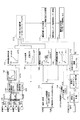
図1は実施の形態1における四輪駆動車の駆動力配分制御装置を示す全体システム図で、1はエンジン、2は自動変速機、3はフロントディファレンシャル、4はリヤディファレンシャル、5は右前輪、6は左前輪、7は右後輪、8は左後輪、9はトルク配分クラッチ、10はトルク配分コントローラ、11は右前輪速センサ、12は左前輪速センサ、13は右後輪速センサ、14は左後輪速センサ、15はアクセル開度センサ、16はエンジン回転センサ、17はATコントローラ、18は前後加速度センサ(前後加速度検出手段)である。
【0020】
この実施の形態1の発明が適用される四輪駆動車は、左右の前輪5,6へはエンジン駆動力が直接伝達され、左右の後輪7,8へはトルク配分クラッチ9を介してエンジン駆動力が伝達される前輪駆動ベースの四輪駆動車である。即ち、トルク配分クラッチ9が締結解放状態であれば、前輪:後輪=100:0のトルク配分比となり、トルク配分クラッチ9がエンジントルクの1/2トルク以上にてにて締結されていれば、前輪:後輪=50:50の等トルク配分比となり、トルク配分コントローラ10からのトルク配分クラッチ9に対する制御指令により、前輪5,6と後輪7,8に伝達されるトルク配分比が、前輪:後輪=100〜50:0〜50の範囲にてトルク配分クラッチ9の締結トルクに応じて可変に制御される。
【0021】
前記トルク配分コントローラ10は、各車輪速センサ11,12,13,14からの車輪速信号と、アクセル開度センサ15からのアクセル開度信号と、エンジン回転センサ16からのエンジン回転信号と、ATコントローラ17からのギア位置信号と、前後加速度センサ18からの前後加速度信号等を入力し、決められた制御則にしたがった演算処理を行い、その演算処理結果による制御指令をトルク配分クラッチ9に出力する。
【0022】
図2は実施の形態1の駆動力配分制御装置に採用されたトルク配分コントローラ10でのトルク配分制御ブロック図である。
【0023】
4輪車輪速計算部100では、各車輪速センサ11,12,13,14からの車輪速信号に基づいて前輪右車輪速度VwFRと前輪左車輪速度VwFLと後輪右車輪速度VwRRと後輪左車輪速度VwRLが計算される。尚、この計算部100は、アンチスキッドブレーキシステム(ABS)が搭載された車両では、ABSコントローラでの計算結果を流用することで省略しても良い。
【0024】
推定車体速計算部101では、各車輪速度VwFR,VwFL,VwRR,VwRLに基づいて推定車体速VFFが計算される。
【0025】
ゲイン計算部102では、計算された推定車体速VFFとゲインマップによりゲインKhが計算される。
【0026】
前後回転数差計算部103では、左右前輪車輪速度VwFR,VwFLの平均値と左右後輪車輪速度VwRR,VwRLの平均値との差により前後回転数差△Vwが計算される。
【0027】
前後回転数差トルク計算部104では、前輪左右輪速差△VwFによりゲインKDFが計算され、Kh×KDFをトータルゲインとして前後回転数差△Vwに応じた前後回転数差トルクT△Vが計算される。
【0028】
旋回半径計算部105では、左右後輪7,8の車輪間隔であるトレッドtと後輪右輪速度VwRRと後輪左輪速度VwRLにより旋回半径Rが計算される。
【0029】
アクセル開度計算部106(アクセル開度検出手段)では、アクセル開度センサ15からのセンサ信号に基づいてアクセル開度ACCが計算される。
【0030】
イニシャルトルク計算部107では、推定車体速VFFによりイニシャルトルクTVが計算される。このイニシャルトルクTVは、VFF=0の時に最も高く推定車体速VFFが大きくなるにしたがって小さなトルクで与えられる。
【0031】
駆動力マップトルク計算部108では、推定車体速VFFと旋回半径Rにより駆動力マップトルクTACCが計算される。この駆動力マップトルクTACCは、推定車体速VFFが20km/h以下の領域で5km/h前後の推定車体速VFFでピークとなるようなトルク特性で与えられると共に、旋回半径Rをパラメータとし、旋回半径が大きいほど大きなトルクで与えられる。
【0032】
アクセル開度感応トルク計算部109では、アクセル開度ACCと旋回半径Rによりアクセル開度感応トルクTSが計算される。このアクセル開度感応トルクTSは、低開度域で上昇し、中開度域で一定で、高開度域で上昇するトルク特性により与えられると共に、旋回半径Rをパラメータとし、旋回半径が大きいほど大きなトルクで与えられる。
【0033】
前後加速度感応ゲイン計算部110(前後加速度感応ゲイン計算手段)では、前後加速度センサ信号による前後加速度XGが大きいほど大きな値による前後加速度感応ゲインKGが計算される。
【0034】
前後加速度感応ゲインフィルタ値計算部111(前後加速度感応ゲインフィルタ値計算手段)では、前記前後加速度感応ゲインKGが増加する特性にゲイン増加を制限するフィルタ処理を加えて前後加速度感応ゲインフィルタ値KGFが計算される。
【0035】
前後加速度感応トルク演算部112(目標トルク演算手段)では、
前後加速度感応ゲインフィルタ値KGFとアクセル開度感応トルクTSとを掛け合わせることで前後加速度感応トルクTGが演算される。
【0036】
目標トルク選択部113では、前後回転数差トルクT△VとイニシャルトルクTVと駆動力マップトルクTACCと前後加速度感応トルクTGのうちセレクトハイにより目標トルクT1が選択される。
【0037】
最終目標トルク決定部114では、目標トルク選択部110により選択された目標トルクT1に対しトルク増加/減少のフィルタ処理を行って最終目標トルクTが決定される。
【0038】
最終目標トルク〜電流変換部115では、最終目標トルクTに対応する電流値Iに電流変換される。
【0039】
最終出力判断部116では、2WDモード(I=0)の判断時以外は最終目標トルク〜電流変換部115により変換された電流値Iが、トルク配分クラッチ9内のソレノイドに出力される。
【0040】
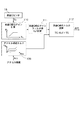
図3は実施の形態1の駆動力配分制御装置に採用されたトルク配分コントローラ10での本発明の特徴的な構成要素を示す制御ブロック図で、18は前後加速度センサ、109はアクセル開度感応トルク計算部、110は前後加速度感応ゲイン計算部、111は前後加速度感応ゲインフィルタ値計算部、112は前後加速度感応トルク演算部である。
【0041】
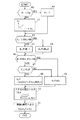
図4は図3に示すトルク配分コントローラ10の構成要素において行われる前後加速度感応トルクの演算処理の流れを示すフローチャートで、以下、各ステップについて説明する。
【0042】
ステップ40では、前後加速度XGが0g未満かどうかが判断され、XG<0の減速時や下り坂発進時等では、ステップ41へ進み、前後加速度感応ゲインKGがKG=1に設定され、XG≧0の加速時や上り坂発進時等では、ステップ42へ進み、前後加速度感応ゲインKGが前後加速度XGの大きさによりテーブルを用いて計算される。以上の処理は、前後加速度感応ゲイン計算部110において行われる。
【0043】
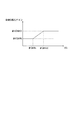
ここで、ステップ42での前後加速度感応ゲインKGの計算は、図5の前後加速度感応ゲインテーブルに示すように、前後加速度XGが第1設定値#GMINまでは一定の最小ゲイン(例えば、#KGMIN=1)とされ、前後加速度XGが第1設定値#GMINから第2設定値#GMAXまでは前後加速度XGの上昇に比例して上昇するゲインとされ、前後加速度XGが第2設定値#GMAX以上になると一定の最大ゲイン(例えば、#KGMAX=1.5〜2.0)とされる。
【0044】
ステップ43では、ステップ42で計算された前後加速度感応ゲインKGが#KGMINを超えているかどうかが判断され、KG≦#KGMIN、つまり、KG=1の時には、ステップ44へ進み、ゲインタイマ値KGTMRがクリアされ、KG>#KGMINの時には、ステップ45へ進み、ゲインタイマ値KGTMRがKGTMR=KGTMR+1というように制御周期毎に1が加算される。
【0045】
そして、ステップ46では、ゲインタイマ値KGTMRが設定タイマ値#KGTIM(例えば、200msecに相当)未満かどうかが判断され、KGTMR<#KGTIMの時には、ステップ47へ進み、今回の前後加速度感応ゲインKGが前回の前後加速度感応ゲインフィルタ値KGFを超えているかどうかによりゲイン増加時かゲイン減少時かがどうかが判断され、KG>KGFであるゲイン増加時には、ステップ48へ進み、前回の前後加速度感応ゲインフィルタ値KGFに制限値#KGLIM(例えば、0.0078g)を加えた値と、今回の前後加速度感応ゲインKGとのセレクトローにより前後加速度感応ゲインフィルタ値KGFが計算される。
【0046】
一方、ステップ46及びステップ47でNOと判断された時、つまり、設定タイマ時間を経過した時、及び、ゲイン減少時は、ステップ49へ進み、今回の前後加速度感応ゲインKGがそのまま前後加速度感応ゲインフィルタ値KGFとされる。以上のステップ43〜ステップ49の処理は、前後加速度感応ゲインフィルタ値計算部111において行われる。
【0047】
ステップ50では、アクセル開度感応トルク計算部109において、割り込み処理によりアクセル開度ACCに応じてアクセル開度感応トルクTSが計算される。、
【0048】
ステップ51では、前後加速度感応トルク演算部112において、前後加速度感応ゲインフィルタ値計算部111にて計算された前後加速度感応ゲインフィルタ値KGFと、アクセル開度感応トルク計算部109にて計算されたアクセル開度感応トルクTSとを掛け合わせることにより前後加速度感応トルクTGが演算される。
【0049】
次に、作用を説明する。
【0050】
[トルク配分制御作用]
【0051】
トルク配分クラッチ9が締結解放されているときは、エンジン1及びトランスミッション2を経過した駆動トルクは前輪5,6のみに伝達される前輪駆動状態となる。そして、トルク配分クラッチ9に対するトルク配分コントローラ10からの制御指令によりトルク配分クラッチ9を締結すると、クラッチ締結トルクの大きさにより、前輪5,6と後輪7,8に伝達されるトルク配分比が制御される。
【0052】
このとき、前後加速度センサ18において、車両に作用する前後加速度XGが検出され、前後加速度感応ゲイン計算部110において、前後加速度XGが大きいほど大きな値による前後加速度感応ゲインKGが計算され、前後加速度感応ゲインフィルタ値計算部111において、前後加速度感応ゲインKGが増加する特性にゲイン増加を制限するフィルタ処理を加えて前後加速度感応ゲインフィルタ値KGFが計算され、前後加速度感応トルク演算部112において、前後加速度感応ゲインフィルタ値KGFを用いて前後加速度感応トルクTGが演算され、前後加速度感応トルクTGが他のトルクより大きいときには、トルク配分コントローラ10からはこの前後加速度感応トルクTGを得る制御指令がトルク配分クラッチ9に対し出力される。
【0053】
ここで、坂道発進時は、発進開始時に既に路面勾配に対応する前後加速度XGが発生していて発進前後での前後加速度XGの上昇が小さい。これに対し、ドライ旋回急加速時は、発進開始時には前後加速度XGがゼロで発進後急激に前後加速度XGが上昇する。
【0054】
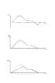
すなわち、坂道発進時には、ゲイン増加を制限するフィルタ処理を加えてもフィルタ処理がほとんど効かず、前後加速度XGが大きいほど大きな値とされる前後加速度感応ゲインKGがほぼそのまま前後加速度感応ゲインフィルタ値KGFとなり、この前後加速度感応ゲインフィルタ値KGFにより大きめに調整された前後加速度感応トルクTGとなることで、発進トラクションの向上を図ることができるし、また、ドライ旋回急加速時には、ゲイン増加を制限するフィルタ処理が効き、図6に示すように、上昇勾配が規定された前後加速度感応ゲインフィルタ値KGFとなり、この前後加速度感応ゲインフィルタ値KGFにより前後加速度感応トルクTGが過大になることが抑えられることで、タイトコーナブレーキング現象の防止を図ることができる。
【0055】
[前後加速度感応ゲイン設定作用]
【0056】
前後加速度感応ゲイン計算部110において、前後加速度XGが第1設定値#GMINまでは一定の最小ゲイン#KGMINとされ、前後加速度XGが第1設定値#GMINから第2設定値#GMAXまでは前後加速度XGの上昇に比例して上昇するゲインとされ、前後加速度XGが第2設定値#GMAX以上になると一定の最大ゲイン#KGMAXとされる。
【0057】
すなわち、前後加速度XGが小さい平坦路での緩加速走行時では、最小ゲイン#KGMINとされることで前後加速度感応トルクTGの補正が効かず、また、前後加速度XGが大きくなる平坦路での急加速発進時等では、一定の最大ゲイン#KGMAXにより前後加速度感応トルクTGの補正限界が規定される。
よって、坂道発進時に多用される第1設定値#GMINから第2設定値#GMAXまでの前後加速度領域において、前後加速度XGで判断される路面勾配が急であるほど前後加速度感応トルクTGを大きくする補正とすることで、坂道発進に絞って発進トラクションの向上を図ることができる。
【0058】
[前後加速度感応ゲインフィルタ値設定作用]
前後加速度感応ゲインフィルタ値計算部111において、図4のステップ43〜ステップ49に示すように、加速方向の前後加速度XGが発生してから設定時間までの間であって、前後加速度感応ゲインKGが増加しているとき、ゲイン増加量を制限するフィルタ処理を加えて前後加速度感応ゲインフィルタ値KGFとされ、それ以外のときには、前後加速度感応ゲインKGがそのまま前後加速度感応ゲインフィルタ値KGFとされる。
【0059】
すなわち、坂道発進時は、停車してから再発進するまでの間の比較的遅い応答性で補正が効けば問題ないのに対し、ドライ旋回急加速時には、前後加速度XGの発生から応答良く補正が効かないことにはタイトコーナブレーキを抑えることができない。
【0060】
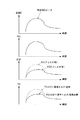
よって、坂道発進時とドライ旋回急加速時での補正を要求する応答性の差に着目し、加速方向の前後加速度XGが発生してから設定時間までの間であって、前後加速度感応ゲインKGが増加しているときに限りフィルタ処理を加えることで、ドライ旋回急加速時において、図7に示すように、フィルタ前のように前後加速度感応トルクTGが過大とならず、確実にタイトコーナブレーキ現象を防止することができる。
【0061】
[前後加速度感応トルク演算作用]
前後加速度感応トルク演算部112において、計算された前後加速度感応ゲインフィルタ値KGFに、アクセル開度計算部106からのアクセル開度ACCに応じて計算されたアクセル開度感応トルクTSを掛け合わせることにより前後加速度感応トルクTGが演算される。
【0062】
すなわち、アクセル開度感応トルクTGは、ドライバのアクセル操作に対応するトルクであり、アクセルの踏み込み操作を行う発進時にはトルクが上昇し、前後駆動力配分として4輪駆動側に移行する。
【0063】
よって、発進操作に対応するアクセル開度感応トルクを前後加速度感応ゲインフィルタ値KGFにより補正することで、坂道発進時に発進トラクション向上の実効を図ることができる。
【0064】
次に、効果を説明する。
【0065】
(1) 車両に作用する前後加速度XGを検出する前後加速度センサ18と、検出される前後加速度XGが大きいほど大きな値による前後加速度感応ゲインKGを計算する前後加速度感応ゲイン計算部110と、前後加速度感応ゲインKGが増加する特性にゲイン増加を制限するフィルタ処理を加えて前後加速度感応ゲインフィルタ値KGFとする前後加速度感応ゲインフィルタ値計算部111と、前後加速度感応ゲインフィルタ値KGFを用いて前後加速度感応トルクTGを演算する前後加速度感応トルク演算部112と、をトルク配分コントローラ10に設けたため、前後加速度情報を坂道判断情報としながら、坂道発進時における発進トラクションの向上と、ドライ旋回急加速時におけるタイトコーナブレーキング現象の防止との両立をうまく達成できる。
【0066】
(2) 前後加速度感応ゲイン計算部110を、前後加速度XGが第1設定値#GMINまでは一定の最小ゲイン#KGMINとし、前後加速度XGが第1設定値#GMINから第2設定値#GMAXまでは前後加速度XGの上昇に比例して上昇するゲインとし、前後加速度XGが第2設定値#GMAX以上になると一定の最大ゲイン#KGMAXとする、つまり、坂道発進時に多用される第1設定値#GMINから第2設定値#GMAXまでの前後加速度領域において、前後加速度XGで判断される路面勾配が急であるほど前後加速度感応トルクTGを大きくする補正とするようにしたため、坂道発進に絞って発進トラクションの向上を図ることができる。
【0067】
(3) 前後加速度感応ゲインフィルタ値計算部111を、加速方向の前後加速度XGが発生してから設定時間までの間であって、前後加速度感応ゲインKGが増加しているとき、ゲイン増加量を制限するフィルタ処理を加えて前後加速度感応ゲインフィルタ値KGFとし、それ以外のときには、前後加速度感応ゲインKGがそのまま前後加速度感応ゲインフィルタ値KGFとする、つまり、加速方向の前後加速度XGが発生してから設定時間までの間であって、前後加速度感応ゲインKGFが増加しているときに限りフィルタ処理を加えるようにしたため、ドライ旋回急加速時において確実にタイトコーナブレーキ現象を防止することができる。
【0068】
(4) 目標トルク演算手段として、計算された前後加速度感応ゲインフィルタ値KGFに、アクセル開度センサ18からのアクセル開度ACCに応じて計算されたアクセル開度感応トルクTSを掛け合わせることにより前後加速度感応トルクTGを演算する前後加速度感応トルク演算部112を設けたため、発進操作に対応するアクセル開度感応トルクTSが前後加速度感応ゲインフィルタ値KGFにより補正されることになり、坂道発進時に発進トラクション向上の実効を図ることができる。
(その他の実施の形態)
【0069】
実施の形態1では、前輪駆動ベースの四輪駆動車への適用例を示したが、後輪駆動ベースの四輪駆動車にも適用することができる。
【0070】
実施の形態1では、目標伝達トルク演算手段として、前後加速度感応ゲインフィルタ値KGFにアクセル開度感応トルクTSを掛け合わせることにより前後加速度感応トルクTGを演算する前後加速度感応トルク演算部112を設けた例を示したが、例えば、目標トルク選択部で選択された目標トルクT1を基準トルクとし、これに前後加速度感応ゲインフィルタ値KGFを掛け合わせて目標伝達トルクを得る例としても良いし、また、エンジン及びトランスミッションを経過して出力される駆動トルクの大きさにより前後輪の重量配分比と一致する駆動トルク配分比とする伝達トルクを基準トルクとし、これに前後加速度感応ゲインフィルタ値KGFを掛け合わせて目標伝達トルクを得る例としても良い。
【図面の簡単な説明】
【図1】実施の形態1における四輪駆動車の駆動力配分制御装置を示す全体システム図である。
【図2】実施の形態1の駆動力配分制御装置に採用されたトルク配分コントローラでのトルク配分制御ブロック図である。
【図3】実施の形態1における駆動力配分制御装置に採用されたトルク配分コントローラでの本発明の特徴的な構成要素を示す制御ブロック図である。図4は図3に示すトルク配分コントローラ10の構成要素において行われる前後加速度感応トルクの演算処理の流れを示すフローチャートのトルク配分コントローラにて行われるリア伝達トルクの演算処理の流れを示すフローチャートである。
【図4】実施の形態1における駆動力配分制御装置のトルク配分コントローラの前後加速度感応ゲイン計算部,前後加速度感応ゲインフィルタ値計算部及び前後加速度感応トルク演算部にて行われる前後加速度感応トルクの演算処理の流れを示すフローチャートである。
【図5】実施の形態1における駆動力配分制御装置のトルク配分コントローラの前後加速度感応ゲイン計算部に設定されている前後加速度感応ゲイン特性図である。
【図6】ドライ旋回急加速時における前後加速度、前後加速度感応ゲイン、前後加速度感応ゲインフィルタ値の各変化状況を示すタイムチャートである。
【図7】ドライ旋回急加速時における前後加速度、前後加速度感応ゲイン、前後加速度感応ゲインフィルタ値、前後加速度感応トルクの各変化状況をフィルタの有無により比較したタイムチャートである。
【符号の説明】
1 エンジン
2 自動変速機
3 フロントディファレンシャル
4 リヤディファレンシャル
5 右前輪
6 左前輪
7 右後輪
8 左後輪
9 トルク配分クラッチ
10 トルク配分コントローラ
11 右前輪速センサ
12 左前輪速センサ
13 右後輪速センサ
14 左後輪速センサ
15 アクセル開度センサ
16 エンジン回転センサ
17 ATコントローラ
18 前後加速度センサ(前後加速度検出手段)
109 アクセル開度感応トルク計算部
110 前後加速度感応ゲイン計算部
111 前後加速度感応ゲインフィルタ値計算部
112 前後加速度感応トルク演算部[0001]
TECHNICAL FIELD OF THE INVENTION
The present invention relates to a driving force distribution control device for a four-wheel drive vehicle in which a torque distribution ratio transmitted to a front wheel and a rear wheel is controlled by a torque distribution actuator provided in a drive system that distributes engine torque to a front wheel and a rear wheel. Belongs to the technical field.
[0002]
[Prior art]
Conventionally, as a driving force distribution control device for a four-wheel drive vehicle, for example, a driving force distribution control device described in JP-A-11-278080 is known.
[0003]
This publication discloses a front-wheel drive-based four-wheel drive vehicle that includes a signal from a longitudinal acceleration sensor as one of input information and controls a driving force distribution ratio between the front and rear wheels by applying a clutch engagement force to a torque distribution clutch. The technique to do is shown.
[0004]
Here, considering the relationship between the driving force distribution control and the vehicle start, when starting on a hill, the running resistance is larger than when starting on a flat road, so if the rear wheel transmission torque amount is increased when starting on a hill, the vehicle starts. Traction (acceleration) is improved.
[0005]
Therefore, in the system using the longitudinal acceleration sensor as described above, a method of determining that the higher the detected longitudinal acceleration is, the greater the gradient of the ascending slope is, and adjusting the rear wheel transmission torque to be larger.
[0006]
[Problems to be solved by the invention]
However, as described above, when the slope is determined by the signal of the longitudinal acceleration sensor, it is erroneously determined to be a steep hill even at the time of rapid acceleration in which a large longitudinal acceleration occurs, and the rear wheel transmission torque is adjusted to be large, so on a dry road surface Attempting to rapidly accelerate a small-radius turn has a problem in that the torque transmitted to the rear wheels becomes excessive and a tight corner braking phenomenon occurs.
[0007]
The problem to be solved by the present invention is to achieve both improvement of starting traction at the start of a hill and prevention of tight corner braking phenomenon at the time of dry turning sudden acceleration while using longitudinal acceleration information as hill determination information. An object of the present invention is to provide a driving force distribution control device for a four-wheel drive vehicle.
[0008]
[Means for Solving the Problems]
According to the first aspect of the present invention, a torque distribution ratio transmitted to the front wheels and the rear wheels is controlled by a control command from a torque distribution controller for a torque distribution clutch provided in a drive system that distributes engine torque to the front wheels and the rear wheels. In a driving force distribution control device for a four-wheel drive vehicle,
Longitudinal acceleration detecting means for detecting longitudinal acceleration acting on the vehicle,
When the longitudinal acceleration detection value is equal to or smaller than the first set value, the minimum gain is constant. Longitudinal acceleration sensitive gain calculating means for calculating longitudinal acceleration sensitive gain by:
A longitudinal acceleration-sensitive gain filter value calculating means for adding a filter process for limiting gain increase to the characteristic in which the longitudinal acceleration-sensitive gain is increased to be a longitudinal acceleration-sensitive gain filter value;
Target torque calculating means for calculating a target torque using the longitudinal acceleration sensitive gain filter value,
Is provided in the torque distribution controller.
[0009]
According to a second aspect of the present invention, in the driving force distribution control device for a four-wheel drive vehicle according to the first aspect,
The longitudinal acceleration sensitive gain calculating means sets a constant minimum gain until the longitudinal acceleration detection value reaches a first set value, and the longitudinal acceleration detection value is proportional to an increase in the longitudinal acceleration detection value from a first set value to a second set value. And a means for setting a constant maximum gain when the longitudinal acceleration detection value is equal to or more than a second set value.
[0010]
According to a third aspect of the present invention, in the driving force distribution control device for a four-wheel drive vehicle according to the first or second aspect,
The longitudinal acceleration-sensitive gain filter value calculating means may perform a filter process for limiting the amount of gain increase when the longitudinal acceleration-sensitive gain is increasing between the time when the longitudinal acceleration in the acceleration direction is generated and the set time. In addition, the present invention is characterized in that a means is used as a longitudinal acceleration-sensitive gain filter value, and otherwise, a calculated longitudinal acceleration-sensitive gain value is used as a longitudinal acceleration-sensitive gain filter value.
[0011]
According to a fourth aspect of the present invention, in the driving force distribution control device for a four-wheel drive vehicle according to the first to third aspects,
The target torque calculating means multiplies the calculated longitudinal acceleration-sensitive gain filter value by the accelerator opening-sensitive torque calculated in accordance with the accelerator opening detected value from the accelerator opening detecting means, thereby obtaining a longitudinal acceleration-sensitive torque. Is calculated.
[0012]
Function and Effect of the Invention
According to the present invention, a torque distribution ratio transmitted to the front wheels and the rear wheels by a control command from a torque distribution controller for a torque distribution clutch provided in a drive system that distributes engine torque to the front wheels and the rear wheels. Is controlled.
At this time, the longitudinal acceleration detecting means detects the longitudinal acceleration acting on the vehicle, and the longitudinal acceleration sensitive gain calculating means sets a constant minimum gain until the longitudinal acceleration detection value reaches a first set value, and sets the longitudinal acceleration detection value to a slope. If the longitudinal acceleration detection value is greater than or equal to the first set value already generated corresponding to the road surface gradient at the start of the start, the longitudinal acceleration sensitive gain is calculated by a larger value, and the longitudinal acceleration sensitive gain filter value calculating means calculates the longitudinal acceleration sensitive gain. The longitudinal acceleration sensitive gain filter value is calculated by adding a filter process for limiting the gain increase to the characteristic of increasing, and the target torque is calculated by the target torque calculating means using the longitudinal acceleration sensitive gain filter value. Indicates that a control command to obtain this target torque is output to the torque distribution clutch. That.
Here, when the vehicle starts on a sloping road, a longitudinal acceleration equal to or greater than the first set value corresponding to the road surface gradient has already been generated at the start of the start, and the increase in the longitudinal acceleration before and after the start is small. On the other hand, during dry turning rapid acceleration, the longitudinal acceleration is zero at the start of the start, and the longitudinal acceleration increases rapidly after the start.
That is, at the start of the slope, even if the filter processing for limiting the gain increase is added, the filter processing is hardly effective, and the longitudinal acceleration detection value is equal to or more than the first set value that is already generated at the start of the slope start corresponding to the road surface gradient, The longitudinal acceleration sensitive gain, which becomes larger as the longitudinal acceleration detected value becomes larger, becomes the longitudinal acceleration sensitive gain filter value as it is, and becomes the target torque that is adjusted to be larger by the longitudinal acceleration sensitive gain filter value. In addition, the filter processing for limiting the gain increase is effective at the time of dry turning rapid acceleration, and the vertical acceleration-sensitive gain filter value in which the rising gradient from a certain minimum gain is specified is obtained. The gain filter value prevents the target torque from becoming excessive, It is possible to prevent the corner braking phenomenon.
Therefore, it is possible to successfully achieve both improvement of the starting traction at the time of starting on a slope and prevention of the tight corner braking phenomenon at the time of dry turning sudden acceleration while using the longitudinal acceleration information as the slope determination information.
[0013]
In the invention according to
That is, at the time of gentle acceleration running on a flat road where the longitudinal acceleration is small, the target gain is not corrected by setting the minimum gain, and at the time of sudden acceleration start on a flat road where the longitudinal acceleration is large, the constant gain is maintained. Defines the correction limit of the target torque.
Therefore, in the longitudinal acceleration region from the first set value to the second set value that is frequently used when starting on a slope, the target torque is increased as the road surface gradient determined by the longitudinal acceleration detected value is steeper, It is possible to improve starting traction by focusing on starting on a slope.
[0014]
According to the third aspect of the present invention, in the longitudinal acceleration-sensitive gain filter value calculating means, when the longitudinal acceleration-sensitive gain is increasing during a period from the occurrence of the longitudinal acceleration in the acceleration direction to the set time, the gain is increased. A filter processing for limiting the amount is added to obtain a longitudinal acceleration-sensitive gain filter value. Otherwise, the calculated longitudinal acceleration-sensitive gain value is used as a longitudinal acceleration-sensitive gain filter value.
In other words, when starting on a slope, there is no problem if the correction is effective with a relatively slow response between the time of stopping and restarting. Without it, tight corner braking cannot be suppressed.
Therefore, focusing on the difference in responsiveness that requires correction between when starting on a slope and when performing dry turning rapid acceleration, the longitudinal acceleration response gain is increased from the occurrence of longitudinal acceleration in the acceleration direction to the set time. By performing the filter processing only when the vehicle is running, the tight corner braking phenomenon can be surely prevented at the time of dry turning sudden acceleration.
[0015]
In the invention according to claim 4, the target torque calculating means multiplies the calculated longitudinal acceleration sensitive gain filter value by the accelerator opening sensitive torque calculated according to the accelerator opening detected value from the accelerator opening detecting means. The longitudinal acceleration-sensitive torque is calculated by combining them.
In other words, the accelerator opening sensitivity torque is a torque corresponding to the accelerator operation of the driver, and the torque increases at the time of starting when the accelerator is depressed, and shifts to the four-wheel drive side as the longitudinal driving force distribution.
Therefore, by correcting the accelerator opening-sensitive torque corresponding to the start operation with the longitudinal acceleration-sensitive gain filter value, it is possible to improve the start traction when starting on a slope.
[0016]
BEST MODE FOR CARRYING OUT THE INVENTION
(Embodiment 1)
[0017]
[0018]
First, the configuration will be described.
[0019]
FIG. 1 is an overall system diagram showing a driving force distribution control device for a four-wheel drive vehicle according to a first embodiment, wherein 1 is an engine, 2 is an automatic transmission, 3 is a front differential, 4 is a rear differential, 5 is a right front wheel, 6 is a left front wheel, 7 is a right rear wheel, 8 is a left rear wheel, 9 is a torque distribution clutch, 10 is a torque distribution controller, 11 is a right front wheel speed sensor, 12 is a left front wheel speed sensor, and 13 is a right rear wheel speed sensor. , 14 is a left rear wheel speed sensor, 15 is an accelerator opening sensor, 16 is an engine rotation sensor, 17 is an AT controller, and 18 is a longitudinal acceleration sensor (longitudinal acceleration detecting means).
[0020]
In the four-wheel drive vehicle to which the invention of the first embodiment is applied, the engine driving force is directly transmitted to the left and right
[0021]
The
[0022]
FIG. 2 is a torque distribution control block diagram of the
[0023]
The four-wheel speed calculation unit 100 calculates the front right wheel speed VwFR, the front left wheel speed VwFL, the rear right wheel speed VwRR, and the rear left wheel based on the wheel speed signals from the respective
[0024]
The estimated vehicle
[0025]
The
[0026]
The front / rear rotation speed
[0027]
The front-rear speed difference
[0028]
The turning
[0029]
The accelerator opening calculating section 106 (accelerator opening detecting means) calculates an accelerator opening ACC based on a sensor signal from the
[0030]
Initial
[0031]
The driving force map
[0032]
The accelerator opening-sensitive
[0033]
The longitudinal acceleration sensitive gain calculation unit 110 (longitudinal acceleration sensitive gain calculating means) calculates the longitudinal acceleration sensitive gain KG with a larger value as the longitudinal acceleration XG based on the longitudinal acceleration sensor signal increases.
[0034]
The longitudinal acceleration-sensitive gain filter value calculation unit 111 (longitudinal acceleration-sensitive gain filter value calculating means) adds a filter process to limit the gain increase to the characteristic of increasing the longitudinal acceleration-sensitive gain KG, and calculates the longitudinal acceleration-sensitive gain filter value KGF. Is calculated.
[0035]
In the longitudinal acceleration-sensitive torque calculation unit 112 (target torque calculation means),
The longitudinal acceleration sensitive torque TG is calculated by multiplying the longitudinal acceleration sensitive gain filter value KGF by the accelerator opening degree sensitive torque TS.
[0036]
In the target
[0037]
The final target
[0038]
The final target torque-
[0039]
The final
[0040]
FIG. 3 is a control block diagram showing characteristic components of the present invention in the
[0041]
FIG. 4 is a flowchart showing the flow of the calculation processing of the longitudinal acceleration sensitive torque performed by the components of the
[0042]
At
[0043]
Here, in the calculation of the longitudinal acceleration sensitive gain KG in
[0044]
In
[0045]
Then, in
[0046]
On the other hand, when NO is determined in
[0047]
In step 50, the accelerator opening-sensitive
[0048]
In
[0049]
Next, the operation will be described.
[0050]
[Torque distribution control action]
[0051]
When the
[0052]
At this time, the
[0053]
Here, when the vehicle starts on a slope, the longitudinal acceleration XG corresponding to the road surface gradient has already been generated at the start of the start, and the increase in the longitudinal acceleration XG before and after the start is small. On the other hand, at the time of dry turning rapid acceleration, the longitudinal acceleration XG is zero at the start of the start, and the longitudinal acceleration XG rapidly increases after the start.
[0054]
That is, when the vehicle starts on a sloping road, even if a filter process for limiting the gain increase is added, the filter process is hardly effective, and the longitudinal acceleration sensitive gain KG, which becomes a larger value as the longitudinal acceleration XG becomes larger, is almost unchanged. With the longitudinal acceleration-sensitive torque TG adjusted to be larger by the longitudinal acceleration-sensitive gain filter value KGF, the starting traction can be improved, and the gain increase is limited during dry turning rapid acceleration. The filtering process is effective, and as shown in FIG. 6, a longitudinal acceleration-sensitive gain filter value KGF with a specified ascending gradient is obtained, and the longitudinal acceleration-sensitive torque TG is prevented from becoming excessive with the longitudinal acceleration-sensitive gain filter value KGF. To prevent the tight corner braking phenomenon Door can be.
[0055]
[Setting action of longitudinal acceleration sensitive gain]
[0056]
In the longitudinal acceleration sensitive
[0057]
That is, at the time of slow acceleration running on a flat road where the longitudinal acceleration XG is small, the correction of the longitudinal acceleration sensitive torque TG is not effective due to the minimum gain #KGMIN, and the sudden acceleration on a flat road where the longitudinal acceleration XG becomes large. At the time of acceleration start or the like, the correction limit of the longitudinal acceleration sensitive torque TG is defined by the constant maximum gain #KGMAX.
Therefore, in the longitudinal acceleration region from the first set value #GMIN to the second set value #GMAX frequently used when starting on a slope, the longitudinal acceleration sensitive torque TG is increased as the road surface gradient determined by the longitudinal acceleration XG is steeper. By making the correction, it is possible to improve the starting traction by focusing on starting on a slope.
[0058]
[Actual setting function of gain filter value in response to longitudinal acceleration]
In the longitudinal acceleration sensitive gain filter
[0059]
In other words, when the vehicle starts on a slope, the correction can be performed with a relatively slow response between the time of stopping and the time when the vehicle restarts. If it doesn't work, tight corner braking cannot be suppressed.
[0060]
Therefore, paying attention to the difference in responsiveness that requires correction between starting on a hill and suddenly accelerating in dry turning, the longitudinal acceleration sensitive gain KG is between the generation of the longitudinal acceleration XG in the acceleration direction and the set time. By applying the filter processing only when is increased, the front-rear acceleration sensitive torque TG does not become excessively large as in the case of the filter at the time of dry turning rapid acceleration as shown in FIG. The phenomenon can be prevented.
[0061]
[Evaluation of longitudinal acceleration-sensitive torque]
The longitudinal acceleration-sensitive
[0062]
That is, the accelerator opening sensitivity torque TG is a torque corresponding to the accelerator operation of the driver, and increases when the accelerator pedal is depressed, and shifts to the four-wheel drive side as the longitudinal driving force distribution.
[0063]
Therefore, by correcting the accelerator opening-sensitive torque corresponding to the start operation with the longitudinal acceleration-sensitive gain filter value KGF, it is possible to improve start traction when starting on a slope.
[0064]
Next, effects will be described.
[0065]
(1) A
[0066]
(2) The longitudinal acceleration
[0067]
(3) The longitudinal acceleration-sensitive gain filter
[0068]
(4) The target torque calculating means multiplies the calculated longitudinal acceleration-sensitive gain filter value KGF by the accelerator opening-sensitive torque TS calculated in accordance with the accelerator opening ACC from the
(Other embodiments)
[0069]
In the first embodiment, an example in which the present invention is applied to a front-wheel drive-based four-wheel drive vehicle has been described. However, the present invention can also be applied to a rear-wheel drive-based four-wheel drive vehicle.
[0070]
In the first embodiment, a longitudinal acceleration sensitive
[Brief description of the drawings]
FIG. 1 is an overall system diagram showing a driving force distribution control device for a four-wheel drive vehicle according to a first embodiment.
FIG. 2 is a torque distribution control block diagram of a torque distribution controller employed in the driving force distribution control device according to the first embodiment.
FIG. 3 is a control block diagram showing characteristic components of the present invention in a torque distribution controller employed in the driving force distribution control device according to the first embodiment. FIG. 4 is a flowchart showing the flow of the calculation process of the rear transmission torque performed by the torque distribution controller in the flowchart showing the flow of the calculation process of the longitudinal acceleration sensitive torque performed by the components of the
FIG. 4 is a diagram illustrating a longitudinal acceleration-sensitive torque calculated by a longitudinal acceleration-sensitive gain calculating unit, a longitudinal acceleration-sensitive gain filter value calculating unit, and a longitudinal acceleration-sensitive torque calculating unit of a torque distribution controller of the driving force distribution controller according to the first embodiment; It is a flowchart which shows the flow of arithmetic processing.
FIG. 5 is a longitudinal acceleration sensitive gain characteristic set in a longitudinal acceleration sensitive gain calculation unit of the torque distribution controller of the driving force distribution control device according to the first embodiment.
FIG. 6 is a time chart showing how the longitudinal acceleration, the longitudinal acceleration-sensitive gain, and the longitudinal acceleration-sensitive gain filter value change during dry turning rapid acceleration.
FIG. 7 is a time chart comparing changes in longitudinal acceleration, longitudinal acceleration-sensitive gain, longitudinal acceleration-sensitive gain filter value, and longitudinal acceleration-sensitive torque during dry turning rapid acceleration with and without a filter.
[Explanation of symbols]
DESCRIPTION OF
109 Accelerator opening sensitive
Claims (4)
車両に作用する前後加速度を検出する前後加速度検出手段と、
前後加速度検出値が第1設定値までは一定の最小ゲインとし、前後加速度検出値が坂道発進開始時に既に路面勾配に対応して発生する第1設定値以上では前後加速度検出値が大きいほど大きな値による前後加速度感応ゲインを計算する前後加速度感応ゲイン計算手段と、
前記前後加速度感応ゲインが増加する特性にゲイン増加を制限するフィルタ処理を加えて前後加速度感応ゲインフィルタ値とする前後加速度感応ゲインフィルタ値計算手段と、
前記前後加速度感応ゲインフィルタ値を用いて目標トルクを演算する目標トルク演算手段と、
を前記トルク配分コントローラに設けたことを特徴とする四輪駆動車の駆動力配分制御装置。A driving force of a four-wheel drive vehicle in which the torque distribution ratio transmitted to the front wheels and the rear wheels is controlled by a control command from a torque distribution controller for a torque distribution clutch provided in a drive system that distributes engine torque to front wheels and rear wheels. In the distribution control device,
Longitudinal acceleration detecting means for detecting longitudinal acceleration acting on the vehicle,
When the longitudinal acceleration detection value is equal to or smaller than the first set value, the minimum gain is constant. Longitudinal acceleration sensitive gain calculating means for calculating longitudinal acceleration sensitive gain by:
A longitudinal acceleration-sensitive gain filter value calculating means for adding a filter process for limiting gain increase to the characteristic in which the longitudinal acceleration-sensitive gain is increased to be a longitudinal acceleration-sensitive gain filter value;
Target torque calculating means for calculating a target torque using the longitudinal acceleration sensitive gain filter value,
Is provided in the torque distribution controller.
前記前後加速度感応ゲイン計算手段を、前後加速度検出値が第1設定値までは一定の最小ゲインとし、前後加速度検出値が第1設定値から第2設定値までは前後加速度検出値の上昇に比例して上昇するゲインとし、前後加速度検出値が第2設定値以上になると一定の最大ゲインとする手段としたことを特徴とする四輪駆動車の駆動力配分制御装置。The driving force distribution control device for a four-wheel drive vehicle according to claim 1,
The longitudinal acceleration sensitive gain calculating means sets a constant minimum gain until the longitudinal acceleration detection value reaches a first set value, and the longitudinal acceleration detection value is proportional to an increase in the longitudinal acceleration detection value from a first set value to a second set value. A drive gain distribution control device for a four-wheel drive vehicle, wherein the gain is increased when the detected longitudinal acceleration value is equal to or greater than a second set value.
前記前後加速度感応ゲインフィルタ値計算手段を、加速方向の前後加速度が発生してから設定時間までの間であって、前後加速度感応ゲインが増加しているとき、ゲイン増加量を制限するフィルタ処理を加えて前後加速度感応ゲインフィルタ値とし、それ以外のときには前後加速度感応ゲイン計算値を前後加速度感応ゲインフィルタ値とする手段としたことを特徴とする四輪駆動車の駆動力配分制御装置。The driving force distribution control device for a four-wheel drive vehicle according to claim 1 or 2,
The longitudinal acceleration-sensitive gain filter value calculating means may perform a filter process for limiting the amount of gain increase when the longitudinal acceleration-sensitive gain is increasing between the time when the longitudinal acceleration in the acceleration direction is generated and the set time. A driving force distribution control device for a four-wheel drive vehicle, characterized in that the means is a longitudinal acceleration-sensitive gain filter value, and in other cases, the longitudinal acceleration-sensitive gain calculation value is a longitudinal acceleration-sensitive gain filter value.
前記目標トルク演算手段を、計算された前後加速度感応ゲインフィルタ値に、アクセル開度検出手段からのアクセル開度検出値に応じて計算されたアクセル開度感応トルクを掛け合わせることにより前後加速度感応トルクを演算する手段としたことを特徴とする四輪駆動車の駆動力配分制御装置。The driving force distribution control device for a four-wheel drive vehicle according to any one of claims 1 to 3,
The target torque calculating means multiplies the calculated longitudinal acceleration-sensitive gain filter value by the accelerator opening-sensitive torque calculated in accordance with the accelerator opening detected value from the accelerator opening detecting means, thereby obtaining a longitudinal acceleration-sensitive torque. A driving force distribution control device for a four-wheel drive vehicle, characterized by means for calculating
Priority Applications (1)
| Application Number | Priority Date | Filing Date | Title |
|---|---|---|---|
| JP2000040447A JP3561908B2 (en) | 2000-02-18 | 2000-02-18 | Driving force distribution control device for four-wheel drive vehicle |
Applications Claiming Priority (1)
| Application Number | Priority Date | Filing Date | Title |
|---|---|---|---|
| JP2000040447A JP3561908B2 (en) | 2000-02-18 | 2000-02-18 | Driving force distribution control device for four-wheel drive vehicle |
Publications (2)
| Publication Number | Publication Date |
|---|---|
| JP2001225663A JP2001225663A (en) | 2001-08-21 |
| JP3561908B2 true JP3561908B2 (en) | 2004-09-08 |
Family
ID=18563820
Family Applications (1)
| Application Number | Title | Priority Date | Filing Date |
|---|---|---|---|
| JP2000040447A Expired - Lifetime JP3561908B2 (en) | 2000-02-18 | 2000-02-18 | Driving force distribution control device for four-wheel drive vehicle |
Country Status (1)
| Country | Link |
|---|---|
| JP (1) | JP3561908B2 (en) |
-
2000
- 2000-02-18 JP JP2000040447A patent/JP3561908B2/en not_active Expired - Lifetime
Also Published As
| Publication number | Publication date |
|---|---|
| JP2001225663A (en) | 2001-08-21 |
Similar Documents
| Publication | Publication Date | Title |
|---|---|---|
| JP4413931B2 (en) | Vehicle and vehicle control device | |
| JP3214169B2 (en) | Differential limit torque control device | |
| EP1104715B1 (en) | Drive-force distribution controller for a four-wheel-drive vehicle | |
| EP1400390A2 (en) | Power distribution control apparatus for four wheel drive vehicle | |
| JP4233794B2 (en) | Driving force distribution control device for four-wheel drive vehicles | |
| JPH11115719A (en) | Power distribution control device for four-wheel drive vehicle | |
| JP2003159952A (en) | Four-wheel drive control device | |
| JP3656511B2 (en) | Driving force control device for four-wheel drive vehicle | |
| JP3539280B2 (en) | Driving force distribution control device for four-wheel drive vehicle | |
| JP3561908B2 (en) | Driving force distribution control device for four-wheel drive vehicle | |
| JP3651327B2 (en) | Driving force control device for four-wheel drive vehicle | |
| JP3716333B2 (en) | Driving force control device for four-wheel drive vehicle | |
| JP3518464B2 (en) | Driving force distribution control device for four-wheel drive vehicle | |
| JP3555132B2 (en) | Driving force distribution control device for four-wheel drive vehicle | |
| JPH05338457A (en) | 4-wheel drive system for vehicles | |
| JP3355767B2 (en) | Differential limit torque control device | |
| JP6753534B2 (en) | Vehicle control method and vehicle control device | |
| JP3506228B2 (en) | Driving force distribution control device for four-wheel drive vehicles | |
| JP3555130B2 (en) | Driving force distribution control device for four-wheel drive vehicle | |
| JP3424768B2 (en) | Driving force distribution control system for left and right wheels and front and rear wheels | |
| JP3555131B2 (en) | Driving force distribution control device for four-wheel drive vehicle | |
| JP3397844B2 (en) | Vehicle differential limiting control device | |
| JP3724072B2 (en) | Brake device for vehicle | |
| JP3506223B2 (en) | Driving force distribution control device for four-wheel drive vehicle | |
| JPH0585339A (en) | Road surface friction coefficient detecting device |
Legal Events
| Date | Code | Title | Description |
|---|---|---|---|
| A977 | Report on retrieval |
Free format text: JAPANESE INTERMEDIATE CODE: A971007 Effective date: 20040130 |
|
| A131 | Notification of reasons for refusal |
Free format text: JAPANESE INTERMEDIATE CODE: A131 Effective date: 20040217 |
|
| A521 | Written amendment |
Free format text: JAPANESE INTERMEDIATE CODE: A523 Effective date: 20040325 |
|
| TRDD | Decision of grant or rejection written | ||
| A01 | Written decision to grant a patent or to grant a registration (utility model) |
Free format text: JAPANESE INTERMEDIATE CODE: A01 Effective date: 20040510 |
|
| A61 | First payment of annual fees (during grant procedure) |
Free format text: JAPANESE INTERMEDIATE CODE: A61 Effective date: 20040523 |
|
| R150 | Certificate of patent or registration of utility model |
Free format text: JAPANESE INTERMEDIATE CODE: R150 Ref document number: 3561908 Country of ref document: JP Free format text: JAPANESE INTERMEDIATE CODE: R150 |
|
| FPAY | Renewal fee payment (event date is renewal date of database) |
Free format text: PAYMENT UNTIL: 20080611 Year of fee payment: 4 |
|
| FPAY | Renewal fee payment (event date is renewal date of database) |
Free format text: PAYMENT UNTIL: 20090611 Year of fee payment: 5 |
|
| FPAY | Renewal fee payment (event date is renewal date of database) |
Free format text: PAYMENT UNTIL: 20090611 Year of fee payment: 5 |
|
| FPAY | Renewal fee payment (event date is renewal date of database) |
Free format text: PAYMENT UNTIL: 20100611 Year of fee payment: 6 |
|
| R250 | Receipt of annual fees |
Free format text: JAPANESE INTERMEDIATE CODE: R250 |
|
| FPAY | Renewal fee payment (event date is renewal date of database) |
Free format text: PAYMENT UNTIL: 20110611 Year of fee payment: 7 |
|
| FPAY | Renewal fee payment (event date is renewal date of database) |
Free format text: PAYMENT UNTIL: 20120611 Year of fee payment: 8 |
|
| FPAY | Renewal fee payment (event date is renewal date of database) |
Free format text: PAYMENT UNTIL: 20120611 Year of fee payment: 8 |
|
| FPAY | Renewal fee payment (event date is renewal date of database) |
Free format text: PAYMENT UNTIL: 20130611 Year of fee payment: 9 |
|
| FPAY | Renewal fee payment (event date is renewal date of database) |
Free format text: PAYMENT UNTIL: 20140611 Year of fee payment: 10 |
|
| EXPY | Cancellation because of completion of term |